EP2360804A1 - Anordnung zum Verbinden von zwei Energiekabeln - Google Patents
Anordnung zum Verbinden von zwei Energiekabeln Download PDFInfo
- Publication number
- EP2360804A1 EP2360804A1 EP09306169A EP09306169A EP2360804A1 EP 2360804 A1 EP2360804 A1 EP 2360804A1 EP 09306169 A EP09306169 A EP 09306169A EP 09306169 A EP09306169 A EP 09306169A EP 2360804 A1 EP2360804 A1 EP 2360804A1
- Authority
- EP
- European Patent Office
- Prior art keywords
- conductors
- connecting element
- insulation
- fixing screws
- arrangement
- Prior art date
- Legal status (The legal status is an assumption and is not a legal conclusion. Google has not performed a legal analysis and makes no representation as to the accuracy of the status listed.)
- Granted
Links
Images

Classifications
-
- H—ELECTRICITY
- H02—GENERATION; CONVERSION OR DISTRIBUTION OF ELECTRIC POWER
- H02G—INSTALLATION OF ELECTRIC CABLES OR LINES, OR OF COMBINED OPTICAL AND ELECTRIC CABLES OR LINES
- H02G15/00—Cable fittings
- H02G15/08—Cable junctions
- H02G15/10—Cable junctions protected by boxes, e.g. by distribution, connection or junction boxes
- H02G15/103—Cable junctions protected by boxes, e.g. by distribution, connection or junction boxes with devices for relieving electrical stress
-
- H—ELECTRICITY
- H02—GENERATION; CONVERSION OR DISTRIBUTION OF ELECTRIC POWER
- H02G—INSTALLATION OF ELECTRIC CABLES OR LINES, OR OF COMBINED OPTICAL AND ELECTRIC CABLES OR LINES
- H02G15/00—Cable fittings
- H02G15/08—Cable junctions
- H02G15/18—Cable junctions protected by sleeves, e.g. for communication cable
- H02G15/184—Cable junctions protected by sleeves, e.g. for communication cable with devices for relieving electrical stress
-
- H—ELECTRICITY
- H01—ELECTRIC ELEMENTS
- H01R—ELECTRICALLY-CONDUCTIVE CONNECTIONS; STRUCTURAL ASSOCIATIONS OF A PLURALITY OF MUTUALLY-INSULATED ELECTRICAL CONNECTING ELEMENTS; COUPLING DEVICES; CURRENT COLLECTORS
- H01R4/00—Electrically-conductive connections between two or more conductive members in direct contact, i.e. touching one another; Means for effecting or maintaining such contact; Electrically-conductive connections having two or more spaced connecting locations for conductors and using contact members penetrating insulation
- H01R4/28—Clamped connections, spring connections
- H01R4/30—Clamped connections, spring connections utilising a screw or nut clamping member
- H01R4/36—Conductive members located under tip of screw
-
- H—ELECTRICITY
- H02—GENERATION; CONVERSION OR DISTRIBUTION OF ELECTRIC POWER
- H02G—INSTALLATION OF ELECTRIC CABLES OR LINES, OR OF COMBINED OPTICAL AND ELECTRIC CABLES OR LINES
- H02G15/00—Cable fittings
- H02G15/007—Devices for relieving mechanical stress
Definitions
- the invention relates to an arrangement for electrically conductive connection of the conductor surrounded by an insulation of two power cables, in which over the two stripped ends of the conductor is arranged a good electrically conductive, tubular connecting element made of metal, whose inner diameter corresponds to the outer diameter of the two conductors, the by means of clamping screws firmly connected to the conductors and whose wall thickness is at least approximately equal to the wall thickness of the insulation of the two conductors ( EP 1 158 638 B1 ).
- the invention has for its object to make the above-described arrangement so that a simplified assembly is possible.
- the conductors 1 and 2 can be stranded or solid. They can be round or segmental. They can be made of copper or aluminum.
- a coupling sleeve M is attached, which consists for example of a prefabricated component of a conductive shield 5, a molded body 6 made of elastic insulating material and a conductive outer coating 7.
- the coating 7 has electrically conductive contact with the outer conductive layers of the two insulations 3 and 4 when the connecting sleeve M is mounted.
- Crosslinked polyethylene is preferably used as the material for the insulations 3 and 4.
- the coupling sleeve M sits with a press fit on the parts enclosed by it.
- the two conductors 1 and 2 are within the in Fig. 1 illustrated connection point by means of a metallic tubular connecting element V electrically conductively connected.
- the connecting element V is made of a metal of high conductivity.
- the inner diameter of its through hole corresponds to the outer diameter of the conductors 1 and 2. It can also be stepped if the two conductors 1 and 2 have different outer diameters.
- At the two axial ends of the connecting element V has the same over a predetermined axial length in sections 8 and 9 a larger diameter relative to the inner diameter.
- the clear diameter and the axial length of the sections 8 and 9 correspond to the outer diameter and the axial length of support surfaces 10 and 11 of the insulations 3 and 4 of the two conductors 1 and 2.
- In the sections 8 and 9 of the connecting element V are distributed over the circumference Threaded holes 12 and 13 for receiving fixing screws 14 (FIG. Fig. 2 ) appropriate.
- the fixing screws 14 are screwed into the threaded holes 12 and 13, which thereby penetrate into the insulation 3 and 4 and connect them firmly to the connecting element V.
- the fixing screws 14 are screwed so far into the connecting element V that they do not protrude to the outside. They can be made of metal or plastic.
- the connecting sleeve M is finally pushed until they are out of Fig. 1 apparent position.
- the arrangement is - as already mentioned - can also be used if the conductors 1 and 2 have different diameters.
- the inner diameter of the through hole of the connecting element V is then adjusted accordingly by gradation. If the insulations 3 and 4 have different diameters, a corresponding step to the connecting element V can be compensated for by an adapted step in the elastic shaped body 6 of the connecting sleeve M.
- the bearing surfaces 10 and 11 of the insulation 3 and 4 can then also have different diameters.
- the clear diameters of the sections 8 and 9 of the connecting element V are adjusted accordingly.
Landscapes
- Cable Accessories (AREA)
Abstract
Description
- Die Erfindung betrifft eine Anordnung zum elektrisch leitenden Verbinden der von einer Isolierung umgebenen Leiter von zwei Energiekabeln, bei welcher über den beiden abisolierten Enden der Leiter ein elektrisch gut leitendes, rohrförmiges Verbindungselement aus Metall angeordnet ist, dessen Innendurchmesser dem Außendurchmesser der beiden Leiter entspricht, das mittels Klemmschrauben fest mit den Leitern verbindbar ist und dessen Wandstärke zumindest annähernd gleich der Wandstärke der Isolierungen der beiden Leiter ist (
EP 1 158 638 B1 ). - Eine derartige Anordnung wird bei der Verbindung von zwei Energiekabeln, insbesondere von zwei Hochspannungskabeln - im folgenden kurz "Kabel" genannt
- innerhalb einer Verbindungsmuffe eingesetzt. Die Verbindungsmuffe selbst ist in heutiger Technik üblicherweise ein vorgefertigtes Bauteil. Sie wird vor dem Verbinden der Leiter der beiden Kabel im aufgeweiteten Zustand auf eines der zu verbindenden Kabel aufgeschoben und dort "geparkt". Eine Verbindungsmuffe besteht beispielsweise aus einem Formkörper aus elastomerem Material, wie EPDM oder Silikon-Kautschuk, in den eine leitfähige Abschirmung für die Verbindungsstelle der Leiter der beiden zu verbindenden Kabel eingebettet ist. Sie kann außerdem mit einer leitfähigen äußeren Beschichtung zum Kontaktieren der äußeren Leitschichten der beiden Kabel versehen sein. In Montageposition umschließt die Verbindungsmuffe die Verbindungsstelle der beiden Leiter und die anschließenden Enden der mit einer äußeren Leitschicht versehenen Isolierungen der beiden Leiter mit Preßsitz. Eine gleichmäßige Verteilung des elektrischen Feldes im Bereich der Verbindungsstelle ist dann sichergestellt.
- Bei der bekannten Anordnung nach der eingangs erwähnten
EP 1 158 638 B1 haben die beiden Enden des Rohres einen im Außendurchmesser reduzierten Endbereich, in dem jeweils eine nach außen offene, umlaufende Nut angebracht ist. An beiden Enden des Rohres ist in Montageposition ein als axial kurzes Rohrstück ausgebildetes, zugfestes Ankerelement angebracht, das jeweils einerseits in eine umlaufende Nut der Isolierungen der beiden Kabel und andererseits in eine der Nuten des Rohres eingreift. Seine äußere Oberfläche schließt sowohl mit dem Rohr als auch mit der jeweiligen Isolierung der beiden Kabel bündig ab. Diese Anordnung hat sich in der Praxis bewährt. Die konstruktive Lösung ist jedoch kompliziert und aufwendig. - Der Erfindung liegt die Aufgabe zugrunde, die eingangs geschilderte Anordnung so zu gestalten, daß eine vereinfachte Montage möglich ist.
- Diese Aufgabe wird gemäß der Erfindung dadurch gelöst,
- daß das Verbindungselement an beiden axialen Enden einen in axialer Richtung begrenzten, nach außen offenen Abschnitt mit einem gegenüber seinem Innendurchmesser erweiterten lichten Durchmesser aufweist,
- daß in den beiden erweiterten Abschnitten, über den Umfang des Verbindungselements verteilt, durchgehende Gewindelöcher zur Aufnahme von Fixierschrauben angebracht sind,
- daß das Verbindungselement in Montageposition mit seinen erweiterten Abschnitten auf an den Enden der Isolierungen der beiden Leiter befindlichen Auflageflächen aufliegt, die auf einer entsprechenden Länge einen reduzierten
- Außendurchmesser haben, und
- daß das Verbindungselement in Montageposition mit den Isolierungen der beiden Leiter mittels der Fixierschrauben fest verbunden ist, welche in die Isolierungen der beiden Leiter hineinragen.
- Die zugfeste Verbindung zwischen rohrförmigem Verbindungselement und Isolierungen ist bei dieser Anordnung einfach ausgeführt. Es brauchen nach Befestigung des Verbindungselements an den Leitern nur noch die Fixierschrauben in die Gewindelöcher desselben eingeschraubt zu werden, bis sie ohne Überstand nach außen in die Isolierungen eingreifen. Gesondert zu montierende Befestigungselemente sind bei dieser Anordnung nicht erforderlich.
- Ein Ausführungsbeispiel des Erfindungsgegenstandes ist in den Zeichnungen dargestellt.
- Es zeigen:
-
Fig. 1 in schematischer Darstellung eine Verbindungsstelle zwischen zwei Hochspannungskabeln teilweise im Schnitt. -
Fig. 2 die Anordnung nach der Erfindung teilweise im Schnitt in vergrößerter Darstellung. -
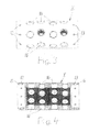
Fig. 3 eine Draufsicht auf ein in der Anordnung verwendetes rohrförmiges Verbindungselement. -
Fig. 4 einen Querschnitt des Verbindungselements nachFig. 3 . - Die aus
Fig. 2 ersichtlichen Leiter 1 und 2 von zwei Energiekabeln - im folgenden weiter kurz "Kabel" genannt - sind durch ein rohrförmiges metallisches Verbindungselement V elektrisch leitend miteinander verbunden, dessen genauerer Aufbau aus denFig. 2 bis 4 hervorgeht. Von den Kabeln sind in denFig. 1 und 2 nur deren Leiter 1 und 2 und die dieselben umgebenden Isolierungen 3 und 4 dargestellt. In der zeichnerischen Darstellung fortgelassen sind eine die Leiter 1 und 2 umgebende Leiterglättung bzw. innere Leitschicht, eine die jeweilige Isolierung 3 oder 4 umgebende äußere Leitschicht und jeweils über derselben liegende weitere Schichten der Kabel, zu denen auch ein stromtragfähiger Schirm oder Metallmantel sowie ein äußerer Mantel aus Isoliermaterial gehören. - Die Leiter 1 und 2 können mehrdrähtig oder massiv sein. Sie können rund oder segmentförmig ausgeführt sein. Sie können aus Kupfer oder Aluminium bestehen. Über der Verbindungsstelle der beiden Leiter 1 und 2 ist eine Verbindungsmuffe M angebracht, die beispielsweise als vorgefertigtes Bauteil aus einer leitfähigen Abschirmung 5, einem Formkörper 6 aus elastischem Isoliermaterial und einer leitfähigen äußeren Beschichtung 7 besteht. Die Beschichtung 7 hat bei montierter Verbindungsmuffe M elektrisch leitenden Kontakt mit den äußeren Leitschichten der beiden Isolierungen 3 und 4. Als Material für die Isolierungen 3 und 4 wird vorzugsweise vernetztes Polyethylen verwendet. Die Verbindungsmuffe M sitzt mit Preßsitz auf den von ihr umschlossenen Teilen.
- Die beiden Leiter 1 und 2 sind innerhalb der in
Fig. 1 dargestellten Verbindungsstelle mittels eines metallischen rohrförmigen Verbindungselements V elektrisch leitend verbunden. Das Verbindungselement V besteht aus einem Metall hoher Leitfähigkeit. Der Innendurchmesser seiner Durchgangsbohrung entspricht dem Außendurchmesser der Leiter 1 und 2. Er kann auch abgestuft sein, wenn die beiden Leiter 1 und 2 unterschiedliche Außendurchmesser haben. An den beiden axialen Enden des Verbindungselements V hat dasselbe auf einer vorgegebenen axialen Länge in Abschnitten 8 und 9 einen gegenüber dem Innendurchmesser größeren lichten Durchmesser. Der lichte Durchmesser sowie die axiale Länge der Abschnitte 8 und 9 entsprechen dem Außendurchmesser und der axialen Länge von Auflageflächen 10 und 11 der Isolierungen 3 und 4 der beiden Leiter 1 und 2. In den Abschnitten 8 und 9 des Verbindungselements V sind über dessen Umfang verteilt Gewindelöcher 12 bzw. 13 zur Aufnahme von Fixierschrauben 14 (Fig. 2 ) angebracht. - Zum Verbinden der beiden Leiter 1 und 2 werden zunächst alle oberhalb der äußeren Leitschicht liegenden Schichten, insbesondere der äußere Mantel, auf einer vorgegebenen Länge von den Enden der beiden Kabel entfernt. Danach werden die Isolierungen 3 und 4 mit ihren äußeren Leitschichten sowie den Leiterglättungen mit einem Radialschnitt durchtrennt und von den Leitern 1 und 2 abgezogen. Auf eines der Kabelenden wird dann die vorgefertigte Verbindungsmuffe M in aufgeweitetem Zustand aufgeschoben. Anschließend werden die Enden der Isolierungen 3 und 4 auf einer vorgegebenen Länge im Durchmesser reduziert, so daß sich die umlaufenden Auflageflächen 10 und 11 ergeben.
- Zur Fertigstellung der Anordnung werden die Leiter 1 und 2 von zwei unterschiedlichen Seiten her in das Verbindungselement V eingesteckt, bis sich ihre Stirnseiten etwa im mittleren Bereich desselben berühren. In dieser Endposition liegen gemäß
Fig. 2 die Abschnitte 8 und 9 des Verbindungselements V auf den Auflagenflächen 10 und 11 der Isolierungen 3 und 4 auf. In dieser Position wird das Verbindungselement V beispielsweise mittels Klemmschrauben 15 fest mit den Leitern 1 und 2 verbunden, die bis zur festen Anlage an den Leitern 1 und 2 in Gewindelöcher 16 eingeschraubt werden können, von denen gemäßFig. 3 und 4 rund um das Verbindungselement V verteilt eine größere Anzahl vorhanden ist. Abschließend werden an beiden Enden des Verbindungselements V die Fixierschrauben 14 in die Gewindelöcher 12 und 13 eingeschraubt, die dabei in die Isolierungen 3 und 4 eindringen und dieselben fest mit dem Verbindungselement V verbinden. Die Fixierschrauben 14 werden so weit in das Verbindungselement V eingeschraubt, daß sie nicht nach außen überstehen. Sie können aus Metall oder aus Kunststoff bestehen. Über die so vorbereitete Verbindungsstelle zwischen den Leitern 1 und 2 wird abschließend die Verbindungsmuffe M geschoben, bis sie die ausFig. 1 ersichtliche Position einnimmt. - Die Anordnung ist - wie schon erwähnt - auch dann einsetzbar, wenn die Leiter 1 und 2 unterschiedliche Durchmesser haben. Der Innendurchmesser der Durchgangsbohrung des Verbindungselements V wird dann durch Abstufung entsprechend angepaßt. Wenn die Isolierungen 3 und 4 unterschiedliche Durchmesser haben, kann eine entsprechende Stufe zum Verbindungselement V durch eine angepaßte Stufe im elastischen Formkörper 6 der Verbindungsmuffe M ausgeglichen werden. Die Auflageflächen 10 und 11 der Isolierungen 3 und 4 können dann ebenfalls unterschiedliche Durchmesser haben. Die lichten Durchmesser der Abschnitte 8 und 9 des Verbindungselements V werden entsprechend angepaßt.
- Die innere Oberfläche der Durchgangsbohrung des Verbindungselements V kann zumindest in den zur Anlage an den Leitern 1 und 2 bestimmten Bereichen mit Vorteil profiliert sein, um einen verbesserten Festsitz desselben auf den Leitern 1 und 2 zu erreichen. Dazu können in der Durchgangsbohrung gemäß
Fig. 4 beispielsweise quer verlaufende Rillen angebracht sein. Die Profilierung kann auch als Gewinde ausgeführt sein oder es kann auch eine Vielzahl von in radialer Richtung nach innen weisenden Vorsprüngen angebracht sein.
Claims (2)
- Anordnung zum elektrisch leitenden Verbinden der von einer Isolierung umgebenen Leiter von zwei Energiekabeln, bei welcher über den beiden abisolierten Enden der Leiter ein elektrisch gut leitendes, rohrförmiges Verbindungselements aus Metall angeordnet ist, dessen Innendurchmesser dem Außendurchmesser der beiden Leiter entspricht, das mittels Klemmschrauben fest mit den Leitern verbindbar ist und dessen Wandstärke zumindest annähernd gleich der Wandstärke der Isolierungen der beiden Leiter ist, dadurch gekennzeichnet,- daß das Verbindungselements (V) an beiden axialen Enden einen in axialer Richtung begrenzten, nach außen offenen Abschnitt (8,9) mit einem gegenüber seinem Innendurchmesser erweiterten lichten Durchmesser aufweist,- daß in den beiden erweiterten Abschnitten (8,9), über den Umfang des Verbindungselements (V) verteilt, durchgehende Gewindelöcher (12,13) zur Aufnahme von Fixierschrauben (14) angebracht sind,- daß das Verbindungselement (V) in Montageposition mit seinen erweiterten Abschnitten (8,9) auf an den Enden der Isolierungen (3,4) der beiden Leiter (1,2) befindlichen Auflageflächen (10,11) aufliegt, die auf einer entsprechenden Länge einen reduzierten Außendurchmesser haben, und- daß das Verbindungselement (V) in Montageposition mit den Isolierungen (3,4) der beiden Leiter (1,2) mittels der Fixierschrauben (14) fest verbunden ist, welche in die Isolierungen (3,4) der beiden Leiter (1,2) hineinragen.
- Anordnung nach Anspruch 1, dadurch gekennzeichnet, daß die Oberfläche der Durchgangsbohrung des Verbindungselements (V) zumindest in den zur Anlage an den Leitern (1,2) bestimmten Bereichen profiliert ist.
Priority Applications (1)
| Application Number | Priority Date | Filing Date | Title |
|---|---|---|---|
| EP09306169.5A EP2360804B1 (de) | 2009-12-02 | 2009-12-02 | Anordnung zum Verbinden von zwei Energiekabeln |
Applications Claiming Priority (1)
| Application Number | Priority Date | Filing Date | Title |
|---|---|---|---|
| EP09306169.5A EP2360804B1 (de) | 2009-12-02 | 2009-12-02 | Anordnung zum Verbinden von zwei Energiekabeln |
Publications (2)
| Publication Number | Publication Date |
|---|---|
| EP2360804A1 true EP2360804A1 (de) | 2011-08-24 |
| EP2360804B1 EP2360804B1 (de) | 2016-05-18 |
Family
ID=42111355
Family Applications (1)
| Application Number | Title | Priority Date | Filing Date |
|---|---|---|---|
| EP09306169.5A Active EP2360804B1 (de) | 2009-12-02 | 2009-12-02 | Anordnung zum Verbinden von zwei Energiekabeln |
Country Status (1)
| Country | Link |
|---|---|
| EP (1) | EP2360804B1 (de) |
Cited By (8)
| Publication number | Priority date | Publication date | Assignee | Title |
|---|---|---|---|---|
| CN104518292A (zh) * | 2013-10-08 | 2015-04-15 | 泰科电子(上海)有限公司 | 用于连接两根电缆的连接器 |
| CN110086113A (zh) * | 2019-05-24 | 2019-08-02 | 通号(长沙)轨道交通控制技术有限公司 | 一种用于潮湿环境的缆线分段检修装置 |
| CN111934108A (zh) * | 2020-10-12 | 2020-11-13 | 广东电网有限责任公司东莞供电局 | 一种多芯导线连接器 |
| EP3934039A1 (de) * | 2020-07-03 | 2022-01-05 | Nexans | Leiterverbinder und kabelverbindungssystem |
| CN114498533A (zh) * | 2022-02-18 | 2022-05-13 | 河南华民电力设计有限公司 | 一种大径电缆接头 |
| EP4297209A1 (de) * | 2022-06-22 | 2023-12-27 | NKT HV Cables AB | Verfahren zum verbinden von leitern in einem vorgefertigten kabelzubehör |
| EP4572049A1 (de) * | 2023-12-13 | 2025-06-18 | NKT HV Cables AB | Stromkabelzubehöranordnung |
| EP4632977A1 (de) * | 2024-04-10 | 2025-10-15 | NKT HV Cables AB | Stromkabelzubehöranordnung |
Citations (5)
| Publication number | Priority date | Publication date | Assignee | Title |
|---|---|---|---|---|
| US3864013A (en) * | 1973-09-19 | 1975-02-04 | Thomas & Betts Corp | Pre-insulated connector for electrical conductors |
| DE2432234A1 (de) * | 1974-07-05 | 1976-01-29 | Felten & Guilleaume Schaltanl | Muffenverbindung fuer starkstromkabel |
| EP0844687A1 (de) * | 1996-11-25 | 1998-05-27 | Alcatel | Elektrische Verbindung von zwei kunststoffisolierten Hochspannungskabeln und Verfahren zum Herstellen einer solchen Verbindung |
| EP1158638A1 (de) * | 2000-05-26 | 2001-11-28 | Nexans | Anordnung zum elektrisch leitenden Verbinden der Leiter von zwei Hochspanungskabeln |
| EP1465312A2 (de) * | 2003-04-01 | 2004-10-06 | SEFAG Ixosil AG | Verbindung von Hochspannungskabeln |
-
2009
- 2009-12-02 EP EP09306169.5A patent/EP2360804B1/de active Active
Patent Citations (5)
| Publication number | Priority date | Publication date | Assignee | Title |
|---|---|---|---|---|
| US3864013A (en) * | 1973-09-19 | 1975-02-04 | Thomas & Betts Corp | Pre-insulated connector for electrical conductors |
| DE2432234A1 (de) * | 1974-07-05 | 1976-01-29 | Felten & Guilleaume Schaltanl | Muffenverbindung fuer starkstromkabel |
| EP0844687A1 (de) * | 1996-11-25 | 1998-05-27 | Alcatel | Elektrische Verbindung von zwei kunststoffisolierten Hochspannungskabeln und Verfahren zum Herstellen einer solchen Verbindung |
| EP1158638A1 (de) * | 2000-05-26 | 2001-11-28 | Nexans | Anordnung zum elektrisch leitenden Verbinden der Leiter von zwei Hochspanungskabeln |
| EP1465312A2 (de) * | 2003-04-01 | 2004-10-06 | SEFAG Ixosil AG | Verbindung von Hochspannungskabeln |
Cited By (10)
| Publication number | Priority date | Publication date | Assignee | Title |
|---|---|---|---|---|
| CN104518292A (zh) * | 2013-10-08 | 2015-04-15 | 泰科电子(上海)有限公司 | 用于连接两根电缆的连接器 |
| CN110086113A (zh) * | 2019-05-24 | 2019-08-02 | 通号(长沙)轨道交通控制技术有限公司 | 一种用于潮湿环境的缆线分段检修装置 |
| EP3934039A1 (de) * | 2020-07-03 | 2022-01-05 | Nexans | Leiterverbinder und kabelverbindungssystem |
| CN111934108A (zh) * | 2020-10-12 | 2020-11-13 | 广东电网有限责任公司东莞供电局 | 一种多芯导线连接器 |
| CN114498533A (zh) * | 2022-02-18 | 2022-05-13 | 河南华民电力设计有限公司 | 一种大径电缆接头 |
| CN114498533B (zh) * | 2022-02-18 | 2024-03-12 | 河南华民电力设计有限公司 | 一种大径电缆接头 |
| EP4297209A1 (de) * | 2022-06-22 | 2023-12-27 | NKT HV Cables AB | Verfahren zum verbinden von leitern in einem vorgefertigten kabelzubehör |
| EP4572049A1 (de) * | 2023-12-13 | 2025-06-18 | NKT HV Cables AB | Stromkabelzubehöranordnung |
| EP4572048A1 (de) * | 2023-12-13 | 2025-06-18 | NKT HV Cables AB | Stromkabelzubehöranordnung |
| EP4632977A1 (de) * | 2024-04-10 | 2025-10-15 | NKT HV Cables AB | Stromkabelzubehöranordnung |
Also Published As
| Publication number | Publication date |
|---|---|
| EP2360804B1 (de) | 2016-05-18 |
Similar Documents
| Publication | Publication Date | Title |
|---|---|---|
| EP2360804B1 (de) | Anordnung zum Verbinden von zwei Energiekabeln | |
| DE2343030C3 (de) | AnschluBvorrichtung für Koaxialkabel | |
| EP2182602B1 (de) | Vorrichtung für eine Verbindungungsstelle zwischen zwei elektrischen Hochspannungskabeln | |
| EP2091121B1 (de) | Vorrichtung für eine Verbindungsstelle zwischen zwei elektrischen Hochspannungskabeln mit unterschiedlichen Durchmessern | |
| DE2132418C2 (de) | Kabelverbinder für Hochspannungskabel | |
| DE19654012C2 (de) | Verfahren zum feuchtigkeitsdichten Anbringen eines Verbindungselements an einem Hochfrequenzkabel | |
| WO2012079644A1 (de) | Kabelverschraubung | |
| EP1158638B1 (de) | Anordnung zum elektrisch leitenden Verbinden der Leiter von zwei Hochspanungskabeln | |
| DE60302953T2 (de) | Verbinder für zwei elektrische Energiekabel und Verbindung mit einem solchen Verbinder | |
| EP1683235B1 (de) | Verbindung zwischen einem Koaxialkabel und einem Steckverbinder und ihr Herstellungsverfahren | |
| WO2001091262A2 (de) | Muffenisolierkörper mit schraubverbinder zur herstellung einer kabelverbindung für mittelspannungs-kunststoffkabel | |
| DE3042595C2 (de) | Aufschiebbare, mit geteiltem Isolierkörper versehene Verbindungsmuffe für kunststoffisolierte Mittelspannungskabel | |
| EP2874236B1 (de) | Kontaktiervorrichtung zum Kontaktieren eines Kabelschirms | |
| EP3047553B1 (de) | Abschirmungsanordnung für hochstromanwendungen | |
| EP3262724B1 (de) | Hv-kabelsatz | |
| EP3358690A1 (de) | Verbindungsmuffe | |
| DE102018116416A1 (de) | Verbindungsmuffe | |
| EP2403087B1 (de) | Anordnung zum Verbinden von zwei papierisolierten Hochspannungskabeln | |
| DE10026088C1 (de) | Muffenisolierkörper mit Schraubverbinder zur Herstellung einer Kabelverbindung für Mittelspannungs-Kunststoffkabel | |
| DE102024125576B3 (de) | Steckeinrichtung | |
| DE19523514B4 (de) | Elektrische Verbindung von zwei kunststoffisolierten Hochspannungskabeln und Verfahren zum Herstellen einer solchen Verbindung | |
| DE102008045637A1 (de) | Anschlussschelle und Satz mit derartigen Anschlussschellen zur radialen Kontaktierung eines axialen Endes einer mehrphasigen koaxialen Stromschiene | |
| EP3627626B1 (de) | Kontaktelement | |
| DE2223394A1 (de) | Kabelgarnitur fuer starkstromkabel | |
| EP3435483B1 (de) | Verbinder für ein hochstromführendes kabel sowie ein verfahren zur herstellung eines solchen verbinders |
Legal Events
| Date | Code | Title | Description |
|---|---|---|---|
| PUAI | Public reference made under article 153(3) epc to a published international application that has entered the european phase |
Free format text: ORIGINAL CODE: 0009012 |
|
| 17P | Request for examination filed |
Effective date: 20100709 |
|
| AK | Designated contracting states |
Kind code of ref document: A1 Designated state(s): AT BE BG CH CY CZ DE DK EE ES FI FR GB GR HR HU IE IS IT LI LT LU LV MC MK MT NL NO PL PT RO SE SI SK SM TR |
|
| AX | Request for extension of the european patent |
Extension state: AL BA RS |
|
| 17Q | First examination report despatched |
Effective date: 20150831 |
|
| REG | Reference to a national code |
Ref country code: DE Ref legal event code: R079 Ref document number: 502009012589 Country of ref document: DE Free format text: PREVIOUS MAIN CLASS: H02G0015103000 Ipc: H01R0004360000 |
|
| GRAP | Despatch of communication of intention to grant a patent |
Free format text: ORIGINAL CODE: EPIDOSNIGR1 |
|
| RIC1 | Information provided on ipc code assigned before grant |
Ipc: H02G 15/103 20060101ALI20151029BHEP Ipc: H02G 15/007 20060101ALI20151029BHEP Ipc: H01R 4/36 20060101AFI20151029BHEP Ipc: H02G 15/184 20060101ALI20151029BHEP |
|
| INTG | Intention to grant announced |
Effective date: 20151201 |
|
| RIN1 | Information on inventor provided before grant (corrected) |
Inventor name: AUE, VOLKER |
|
| GRAS | Grant fee paid |
Free format text: ORIGINAL CODE: EPIDOSNIGR3 |
|
| GRAA | (expected) grant |
Free format text: ORIGINAL CODE: 0009210 |
|
| AK | Designated contracting states |
Kind code of ref document: B1 Designated state(s): AT BE BG CH CY CZ DE DK EE ES FI FR GB GR HR HU IE IS IT LI LT LU LV MC MK MT NL NO PL PT RO SE SI SK SM TR |
|
| REG | Reference to a national code |
Ref country code: GB Ref legal event code: FG4D Free format text: NOT ENGLISH |
|
| REG | Reference to a national code |
Ref country code: CH Ref legal event code: EP |
|
| REG | Reference to a national code |
Ref country code: IE Ref legal event code: FG4D Free format text: LANGUAGE OF EP DOCUMENT: GERMAN Ref country code: AT Ref legal event code: REF Ref document number: 801172 Country of ref document: AT Kind code of ref document: T Effective date: 20160615 |
|
| REG | Reference to a national code |
Ref country code: DE Ref legal event code: R096 Ref document number: 502009012589 Country of ref document: DE |
|
| REG | Reference to a national code |
Ref country code: NL Ref legal event code: FP |
|
| REG | Reference to a national code |
Ref country code: LT Ref legal event code: MG4D |
|
| PG25 | Lapsed in a contracting state [announced via postgrant information from national office to epo] |
Ref country code: NO Free format text: LAPSE BECAUSE OF FAILURE TO SUBMIT A TRANSLATION OF THE DESCRIPTION OR TO PAY THE FEE WITHIN THE PRESCRIBED TIME-LIMIT Effective date: 20160818 Ref country code: LT Free format text: LAPSE BECAUSE OF FAILURE TO SUBMIT A TRANSLATION OF THE DESCRIPTION OR TO PAY THE FEE WITHIN THE PRESCRIBED TIME-LIMIT Effective date: 20160518 Ref country code: FI Free format text: LAPSE BECAUSE OF FAILURE TO SUBMIT A TRANSLATION OF THE DESCRIPTION OR TO PAY THE FEE WITHIN THE PRESCRIBED TIME-LIMIT Effective date: 20160518 |
|
| PG25 | Lapsed in a contracting state [announced via postgrant information from national office to epo] |
Ref country code: ES Free format text: LAPSE BECAUSE OF FAILURE TO SUBMIT A TRANSLATION OF THE DESCRIPTION OR TO PAY THE FEE WITHIN THE PRESCRIBED TIME-LIMIT Effective date: 20160518 Ref country code: SE Free format text: LAPSE BECAUSE OF FAILURE TO SUBMIT A TRANSLATION OF THE DESCRIPTION OR TO PAY THE FEE WITHIN THE PRESCRIBED TIME-LIMIT Effective date: 20160518 Ref country code: GR Free format text: LAPSE BECAUSE OF FAILURE TO SUBMIT A TRANSLATION OF THE DESCRIPTION OR TO PAY THE FEE WITHIN THE PRESCRIBED TIME-LIMIT Effective date: 20160819 Ref country code: HR Free format text: LAPSE BECAUSE OF FAILURE TO SUBMIT A TRANSLATION OF THE DESCRIPTION OR TO PAY THE FEE WITHIN THE PRESCRIBED TIME-LIMIT Effective date: 20160518 Ref country code: LV Free format text: LAPSE BECAUSE OF FAILURE TO SUBMIT A TRANSLATION OF THE DESCRIPTION OR TO PAY THE FEE WITHIN THE PRESCRIBED TIME-LIMIT Effective date: 20160518 Ref country code: PT Free format text: LAPSE BECAUSE OF FAILURE TO SUBMIT A TRANSLATION OF THE DESCRIPTION OR TO PAY THE FEE WITHIN THE PRESCRIBED TIME-LIMIT Effective date: 20160919 |
|
| REG | Reference to a national code |
Ref country code: FR Ref legal event code: PLFP Year of fee payment: 8 |
|
| PG25 | Lapsed in a contracting state [announced via postgrant information from national office to epo] |
Ref country code: SK Free format text: LAPSE BECAUSE OF FAILURE TO SUBMIT A TRANSLATION OF THE DESCRIPTION OR TO PAY THE FEE WITHIN THE PRESCRIBED TIME-LIMIT Effective date: 20160518 Ref country code: RO Free format text: LAPSE BECAUSE OF FAILURE TO SUBMIT A TRANSLATION OF THE DESCRIPTION OR TO PAY THE FEE WITHIN THE PRESCRIBED TIME-LIMIT Effective date: 20160518 Ref country code: DK Free format text: LAPSE BECAUSE OF FAILURE TO SUBMIT A TRANSLATION OF THE DESCRIPTION OR TO PAY THE FEE WITHIN THE PRESCRIBED TIME-LIMIT Effective date: 20160518 Ref country code: CZ Free format text: LAPSE BECAUSE OF FAILURE TO SUBMIT A TRANSLATION OF THE DESCRIPTION OR TO PAY THE FEE WITHIN THE PRESCRIBED TIME-LIMIT Effective date: 20160518 Ref country code: EE Free format text: LAPSE BECAUSE OF FAILURE TO SUBMIT A TRANSLATION OF THE DESCRIPTION OR TO PAY THE FEE WITHIN THE PRESCRIBED TIME-LIMIT Effective date: 20160518 |
|
| REG | Reference to a national code |
Ref country code: DE Ref legal event code: R097 Ref document number: 502009012589 Country of ref document: DE |
|
| PG25 | Lapsed in a contracting state [announced via postgrant information from national office to epo] |
Ref country code: PL Free format text: LAPSE BECAUSE OF FAILURE TO SUBMIT A TRANSLATION OF THE DESCRIPTION OR TO PAY THE FEE WITHIN THE PRESCRIBED TIME-LIMIT Effective date: 20160518 Ref country code: SM Free format text: LAPSE BECAUSE OF FAILURE TO SUBMIT A TRANSLATION OF THE DESCRIPTION OR TO PAY THE FEE WITHIN THE PRESCRIBED TIME-LIMIT Effective date: 20160518 |
|
| PLBE | No opposition filed within time limit |
Free format text: ORIGINAL CODE: 0009261 |
|
| STAA | Information on the status of an ep patent application or granted ep patent |
Free format text: STATUS: NO OPPOSITION FILED WITHIN TIME LIMIT |
|
| 26N | No opposition filed |
Effective date: 20170221 |
|
| PG25 | Lapsed in a contracting state [announced via postgrant information from national office to epo] |
Ref country code: BE Free format text: LAPSE BECAUSE OF NON-PAYMENT OF DUE FEES Effective date: 20161231 Ref country code: SI Free format text: LAPSE BECAUSE OF FAILURE TO SUBMIT A TRANSLATION OF THE DESCRIPTION OR TO PAY THE FEE WITHIN THE PRESCRIBED TIME-LIMIT Effective date: 20160518 |
|
| PG25 | Lapsed in a contracting state [announced via postgrant information from national office to epo] |
Ref country code: MC Free format text: LAPSE BECAUSE OF FAILURE TO SUBMIT A TRANSLATION OF THE DESCRIPTION OR TO PAY THE FEE WITHIN THE PRESCRIBED TIME-LIMIT Effective date: 20160518 |
|
| REG | Reference to a national code |
Ref country code: CH Ref legal event code: PL |
|
| GBPC | Gb: european patent ceased through non-payment of renewal fee |
Effective date: 20161202 |
|
| REG | Reference to a national code |
Ref country code: IE Ref legal event code: MM4A |
|
| PG25 | Lapsed in a contracting state [announced via postgrant information from national office to epo] |
Ref country code: CH Free format text: LAPSE BECAUSE OF NON-PAYMENT OF DUE FEES Effective date: 20161231 Ref country code: LI Free format text: LAPSE BECAUSE OF NON-PAYMENT OF DUE FEES Effective date: 20161231 Ref country code: LU Free format text: LAPSE BECAUSE OF NON-PAYMENT OF DUE FEES Effective date: 20161202 |
|
| PG25 | Lapsed in a contracting state [announced via postgrant information from national office to epo] |
Ref country code: GB Free format text: LAPSE BECAUSE OF NON-PAYMENT OF DUE FEES Effective date: 20161202 Ref country code: IE Free format text: LAPSE BECAUSE OF NON-PAYMENT OF DUE FEES Effective date: 20161202 |
|
| REG | Reference to a national code |
Ref country code: FR Ref legal event code: PLFP Year of fee payment: 9 |
|
| REG | Reference to a national code |
Ref country code: BE Ref legal event code: MM Effective date: 20161231 |
|
| REG | Reference to a national code |
Ref country code: AT Ref legal event code: MM01 Ref document number: 801172 Country of ref document: AT Kind code of ref document: T Effective date: 20161202 |
|
| PG25 | Lapsed in a contracting state [announced via postgrant information from national office to epo] |
Ref country code: AT Free format text: LAPSE BECAUSE OF NON-PAYMENT OF DUE FEES Effective date: 20161202 Ref country code: HU Free format text: LAPSE BECAUSE OF FAILURE TO SUBMIT A TRANSLATION OF THE DESCRIPTION OR TO PAY THE FEE WITHIN THE PRESCRIBED TIME-LIMIT; INVALID AB INITIO Effective date: 20091202 Ref country code: CY Free format text: LAPSE BECAUSE OF FAILURE TO SUBMIT A TRANSLATION OF THE DESCRIPTION OR TO PAY THE FEE WITHIN THE PRESCRIBED TIME-LIMIT Effective date: 20160518 |
|
| PG25 | Lapsed in a contracting state [announced via postgrant information from national office to epo] |
Ref country code: IS Free format text: LAPSE BECAUSE OF FAILURE TO SUBMIT A TRANSLATION OF THE DESCRIPTION OR TO PAY THE FEE WITHIN THE PRESCRIBED TIME-LIMIT Effective date: 20160518 Ref country code: MK Free format text: LAPSE BECAUSE OF FAILURE TO SUBMIT A TRANSLATION OF THE DESCRIPTION OR TO PAY THE FEE WITHIN THE PRESCRIBED TIME-LIMIT Effective date: 20160518 Ref country code: TR Free format text: LAPSE BECAUSE OF FAILURE TO SUBMIT A TRANSLATION OF THE DESCRIPTION OR TO PAY THE FEE WITHIN THE PRESCRIBED TIME-LIMIT Effective date: 20160518 |
|
| PG25 | Lapsed in a contracting state [announced via postgrant information from national office to epo] |
Ref country code: BG Free format text: LAPSE BECAUSE OF FAILURE TO SUBMIT A TRANSLATION OF THE DESCRIPTION OR TO PAY THE FEE WITHIN THE PRESCRIBED TIME-LIMIT Effective date: 20160518 |
|
| PG25 | Lapsed in a contracting state [announced via postgrant information from national office to epo] |
Ref country code: MT Free format text: LAPSE BECAUSE OF FAILURE TO SUBMIT A TRANSLATION OF THE DESCRIPTION OR TO PAY THE FEE WITHIN THE PRESCRIBED TIME-LIMIT Effective date: 20160518 |
|
| PGFP | Annual fee paid to national office [announced via postgrant information from national office to epo] |
Ref country code: NL Payment date: 20231220 Year of fee payment: 15 |
|
| REG | Reference to a national code |
Ref country code: NL Ref legal event code: MM Effective date: 20250101 |
|
| PG25 | Lapsed in a contracting state [announced via postgrant information from national office to epo] |
Ref country code: NL Free format text: LAPSE BECAUSE OF NON-PAYMENT OF DUE FEES Effective date: 20250101 |
|
| PGFP | Annual fee paid to national office [announced via postgrant information from national office to epo] |
Ref country code: DE Payment date: 20251211 Year of fee payment: 17 |
|
| PGFP | Annual fee paid to national office [announced via postgrant information from national office to epo] |
Ref country code: IT Payment date: 20251223 Year of fee payment: 17 |
|
| PGFP | Annual fee paid to national office [announced via postgrant information from national office to epo] |
Ref country code: FR Payment date: 20251222 Year of fee payment: 17 |