EP2360621A1 - Procedure for detecting a target in an image taken from a vehicle flying over a celestial body - Google Patents
Procedure for detecting a target in an image taken from a vehicle flying over a celestial body Download PDFInfo
- Publication number
- EP2360621A1 EP2360621A1 EP11150856A EP11150856A EP2360621A1 EP 2360621 A1 EP2360621 A1 EP 2360621A1 EP 11150856 A EP11150856 A EP 11150856A EP 11150856 A EP11150856 A EP 11150856A EP 2360621 A1 EP2360621 A1 EP 2360621A1
- Authority
- EP
- European Patent Office
- Prior art keywords
- pixel
- background
- detection
- estimated
- value
- Prior art date
- Legal status (The legal status is an assumption and is not a legal conclusion. Google has not performed a legal analysis and makes no representation as to the accuracy of the status listed.)
- Granted
Links
- 238000000034 method Methods 0.000 title claims abstract description 39
- 238000001514 detection method Methods 0.000 claims abstract description 156
- 238000012360 testing method Methods 0.000 claims abstract description 68
- 230000014509 gene expression Effects 0.000 claims description 35
- 230000002123 temporal effect Effects 0.000 claims description 13
- 238000011156 evaluation Methods 0.000 claims description 12
- 238000005259 measurement Methods 0.000 claims description 11
- 230000006870 function Effects 0.000 description 46
- 230000003287 optical effect Effects 0.000 description 20
- 238000004364 calculation method Methods 0.000 description 8
- 238000012545 processing Methods 0.000 description 6
- 230000003071 parasitic effect Effects 0.000 description 5
- 230000003111 delayed effect Effects 0.000 description 3
- 230000005855 radiation Effects 0.000 description 3
- 238000003657 Likelihood-ratio test Methods 0.000 description 2
- 238000010586 diagram Methods 0.000 description 2
- 239000011159 matrix material Substances 0.000 description 2
- 230000009965 odorless effect Effects 0.000 description 2
- 230000003068 static effect Effects 0.000 description 2
- 101100412394 Drosophila melanogaster Reg-2 gene Proteins 0.000 description 1
- 241000897276 Termes Species 0.000 description 1
- 230000003321 amplification Effects 0.000 description 1
- 238000013459 approach Methods 0.000 description 1
- 238000004590 computer program Methods 0.000 description 1
- 238000005315 distribution function Methods 0.000 description 1
- 238000001914 filtration Methods 0.000 description 1
- 238000010304 firing Methods 0.000 description 1
- 238000009472 formulation Methods 0.000 description 1
- 230000010354 integration Effects 0.000 description 1
- 239000000203 mixture Substances 0.000 description 1
- 238000003199 nucleic acid amplification method Methods 0.000 description 1
- 230000000750 progressive effect Effects 0.000 description 1
- 230000000306 recurrent effect Effects 0.000 description 1
- 238000000528 statistical test Methods 0.000 description 1
- 230000007704 transition Effects 0.000 description 1
Images


Classifications
-
- G—PHYSICS
- G06—COMPUTING; CALCULATING OR COUNTING
- G06T—IMAGE DATA PROCESSING OR GENERATION, IN GENERAL
- G06T7/00—Image analysis
- G06T7/10—Segmentation; Edge detection
- G06T7/11—Region-based segmentation
-
- G—PHYSICS
- G06—COMPUTING; CALCULATING OR COUNTING
- G06T—IMAGE DATA PROCESSING OR GENERATION, IN GENERAL
- G06T7/00—Image analysis
- G06T7/10—Segmentation; Edge detection
- G06T7/136—Segmentation; Edge detection involving thresholding
-
- G—PHYSICS
- G06—COMPUTING; CALCULATING OR COUNTING
- G06T—IMAGE DATA PROCESSING OR GENERATION, IN GENERAL
- G06T7/00—Image analysis
- G06T7/10—Segmentation; Edge detection
- G06T7/194—Segmentation; Edge detection involving foreground-background segmentation
-
- G—PHYSICS
- G06—COMPUTING; CALCULATING OR COUNTING
- G06V—IMAGE OR VIDEO RECOGNITION OR UNDERSTANDING
- G06V10/00—Arrangements for image or video recognition or understanding
- G06V10/20—Image preprocessing
- G06V10/255—Detecting or recognising potential candidate objects based on visual cues, e.g. shapes
Definitions
- the present invention belongs to the field of the exploitation of images obtained by an onboard optical sensor aboard a vehicle flying over the earth. More particularly, the present invention relates to a method of detecting targets in an image or sequence of images substantially representing the same scene on the surface of a celestial body such as the Earth.
- targets is meant any punctual event that appears in an image.
- the invention finds a particularly advantageous application, although in no way limiting, in the detection of targets of the ballistic missile type, according to images acquired by an optical matrix sensor embedded in a satellite in Earth orbit.
- the invention could also be applied to the detection of forest fire departures, for example.
- the images acquired by such sensors are generally in the form of pixel matrices, arranged in rows and columns, each pixel representing a portion of an observed scene.
- the actual dimensions of the targets are generally of smaller dimensions than the portions represented by the pixels of the images.
- the dimensions of the targets considered in relation to the dimensions of an image, are generally pixellic (that is to say at the pixel scale), or even sub-pixellic (that is to say less than the pixel). .
- detection is performed by comparing, for each pixel, the measured radiometry, to which the background has been previously subtracted, to a predefined threshold which is the same for all the pixels of the image.
- a drawback of such an approach lies in the fact that the performance of the detection, in particular expressed in the form of a false alarm probability (that is to say the probability of detection of a target in the first instance).
- 'no target' depend on the signal-to-noise ratio in the image.
- the signal-to-noise ratio can vary from one pixel to another, depending on the observed scene represented by the background of the image.
- the measured signal level for a cloud will generally be greater than the level of a signal measured in the absence of a cloud.
- the noise level also depends on the scene observed.
- the photonic noise, introduced by the optical sensor can be modeled by a Normal distribution whose variance would be equal to the level of the signal received from the observed scene portion. So we understand that the noise level is not necessarily the same from one pixel to another.
- a pixel at the cloud boundary will correspond, from one image to another, to a cloudy bottom or to a bottom of the Earth, and it is understood that the passage from a signal corresponding to a terrestrial background to a signal corresponding to a cloudy background may cause false alarm.
- the present invention aims to provide a target detection method whose performance will be improved over known methods.
- the present invention aims to provide a detection method whose performance, in particular expressed in the form of false alarm probability, are substantially the same regardless of the signal level detected in an image.
- the present invention also aims at providing a detection method some embodiments of which are robust in the presence of residual shifts between images acquired successively, shifts which would be due in particular to registration errors induced by parasitic movements of the line of sight of the optical sensor.
- Such provisions make it possible, because the bottom estimation error is taken into account to determine the value of the at least one threshold in each pixel to be evaluated, to better control the performance of the method of detection. In particular, such provisions make it possible to better control the probability of false alarm of the detection method.
- the estimated statistical characteristics of the estimation error of the bottom in a pixel to be evaluated are at least one standard deviation of the estimation error in this pixel.
- the value of the at least one threshold associated with a pixel to be evaluated is determined by replacing, in the determination of the value of the at least one threshold, the background estimated in this pixel by a replacement background equal to a function of said estimated background and the estimated standard deviation of the estimation error in this pixel.
- the value of the at least one threshold in this pixel is expressed in a first time as a function of the estimated background in this pixel, then the value of the at least one threshold in this pixel is determined by replacing the estimated bottom in this pixel by the estimated bottom in this pixel increased by an amount representative of the estimation error of the bottom in this pixel, this quantity being for example proportional to the estimated standard deviation of the estimation error of the background in this pixel, the proportionality constant being advantageously the same in each pixel to be evaluated.
- the estimated statistical characteristics of the estimation error of the bottom in a pixel to be evaluated are at least one function representative of a probability density of the estimation error of the background. this pixel.
- the probability of false alarm of the detection test in this pixel is expressed as a function of the value of at least one threshold in this pixel, of the estimated background in this pixel, and of said density of estimated probability of the estimation error of the background, then the value of said at least one threshold in this pixel is determined as a function of said estimated background in this pixel and of a statistical draw of a set of realizations of the error of estimating the background in this pixel according to said probability density, so that the probability of false alarm in this pixel is equal to or less than a predefined value.
- the detection method comprises one or more of the following characteristics, taken separately or in any technically possible combination.
- the estimated background is used to model, in the determination of the value of the at least one threshold in each pixel to be evaluated, an unsteady noise whose characteristics depend on a level of the signal measured in this pixel, preferably an unsteady photonic noise.
- an unsteady noise whose characteristics depend on a level of the signal measured in this pixel, preferably an unsteady photonic noise.
- the step of estimating the background and estimating the statistical characteristics of the bottom estimation error uses a Kalman filter taking into account a pattern of evolution of the background of the detection image. .
- the bottom evolution model of the at least one detection image comprises a spatial evolution component and a temporal evolution component.
- the spatial evolution component and the temporal evolution component are modeled, for a pixel to be evaluated, by normal laws of zero means and respective standard deviations determined as a function of the pixel values of a group. pixels around the pixel to be evaluated.
- the background of a detection image is estimated as a function of at least one image, called the "estimation image", each estimation image being acquired prior to the detection image and being separated from said image detection by a non-zero delay equal to or greater than a predefined time of appearance of a target.
- estimate image a function of at least one image, called the "estimation image”
- each estimation image being acquired prior to the detection image and being separated from said image detection by a non-zero delay equal to or greater than a predefined time of appearance of a target.
- At least two thresholds are determined for each pixel to be evaluated, and in which the value of a first threshold in this pixel is determined so as to ensure that the probability of false alarm in this pixel is theoretically equal to or less than one.
- first predefined value and the value a second threshold in this pixel is determined so as to ensure that the detection probability in this pixel is theoretically equal to or greater than a second predefined value.
- the present invention relates to a method for detecting targets in an image, called a "detection image", acquired by a sensor embedded in a vehicle flying over a celestial body, preferably the Earth.
- an image is preferably a two-dimensional image, constituted for example by a matrix of pixels.
- Each pixel represents a portion of a scene observed from the vehicle flying over the Earth.
- An observed scene corresponds to an area on the surface of the Earth, some parts of which are obscured, notably by clouds.
- the sensor is preferably an optical sensor.
- it is a sensor that measures the radiation of the scene observed in the infrared wavelengths domain.
- the vehicle embedding the optical sensor, can be of any type adapted to the acquisition of successive images of the same scene observed.
- the vehicle is a satellite orbiting the Earth, preferably a geostationary orbit.
- the vehicle is an aircraft, such as a helicopter.
- target is generally meant any event modifying the background of the image.
- the background of the image corresponds to the essentially static part of the observed scene, that is to say whose variations are slow compared to the time of appearance of a target (which depends on the type of target considered).
- the present invention finds an advantageous application in the detection of targets of the air-craft type, for example an aircraft (airplane, helicopter) or a propelled phase missile.
- the implementation of the target detection method according to the invention is for example provided by a computing device (microcontroller, computer equipped with a microprocessor, etc.).
- the computing device includes storage means (magnetic hard disk, flash memory, optical disk, etc.) in which a computer program product is stored in the form of a set of program code instructions to be executed. to implement the steps of the method according to the invention, as well as images acquired by the optical sensor.
- the computing device also comprises specialized integrated circuits, of the ASIC, FPGA, etc. type, adapted to implement all or part of the steps of one or more methods according to the invention.
- the computing device is preferably embedded with the optical sensor in the vehicle flying over the Earth in the case of a real-time processing, adapted for example to the detection of ballistic missiles.
- the computing device is embedded with the optical sensor in the vehicle, or it is deported, that is to say located in a ground station or in a second vehicle flying over the Earth.
- An image acquired at a time t is designated by y (t).
- the image y (t) consists of a plurality of pixels, whose values are designated y (p, t), where p denotes the index of a pixel of the image.
- p is between 1 and N L xN c , where N L denotes the number of pixel lines of the image y (t) and N c denotes the number of columns of said image.
- the noise b (p, t) has various origins. In particular, it can be modeled as the sum of a noise b E (p, t) of electronic origin, and a noise b p (p, t) of photonic origin.
- the electronic noise b E (p, t) represents a measurement noise of the optical sensor.
- the electronic noise is generally modeled by a random variable B E (p, t) Gaussian, which follows a law of probabilities Normal N (0, ⁇ 2 E ), da zero mean value and standard deviation ⁇ E independent of the scene observed.
- the photon noise b p (p, t) takes into account the random nature of the measurement of the number of photons.
- Photon noise is usually modeled by a random variable B p (p, t) that follows a Poisson probability law. Given the large number of photons received, and in application of the law of large numbers, this probability law is sometimes approximated by a normal law N (O, x (p, t)) of mean value zero and variance x ( p, t).
- the noise b (p, t) can be modeled by a random variable B (p, t) Gaussian: B p ⁇ t ⁇ NOT ⁇ 0 , ⁇ 2 E + x p ⁇ t
- a B (p) and a G (p) can be estimated in any pixel by implementing methods known to those skilled in the art. For the sake of clarity of the description, but by no means limiting of the invention, it is considered in the remainder of the description that B (p) is equal to zero and that G (p) is equal to one.
- the equations given below can be generalized to arbitrary values of a B (p) and a G (p), starting from equations (4) and (5).
- the figure 1 schematically represents the method of detecting targets in an image, called a "detection image”.
- the target detection method mainly comprises a step of estimating the background of the detection image, a threshold determination step for each pixel to be evaluated, and a step of evaluating a detection test by relative to the determined thresholds, in each pixel to be evaluated of the detection image.
- the detection of targets may be restricted to a subset of pixels of a detection image, or that, on the contrary, the detection may be carried out over the entire detection image.
- the evaluation of the detection test can be limited to a subset of pixels representing an area around a missile firing base.
- the bottom of said pixel must be estimated (step 10) before determining the value of the associated threshold (step 20), which threshold must be determined before evaluating the detection test (step 30). ) for said given pixel.
- the estimation, determination and evaluation steps are performed. successively for each pixel to be evaluated.
- the estimation step is performed for all the pixels to be evaluated, and then the threshold determination and detection test evaluation steps are performed successively for each pixel to be evaluated.
- the detection method may comprise other steps, such as for example a preliminary step, called “registration”, during which the images acquired are recalibrated with respect to each other, to compensate for shifts introduced. by the parasitic movements of the line of sight of the optical sensor during the acquisition.
- registration step can be implemented according to any registration method known to those skilled in the art.
- the steps of the detection method are preferably executed recurrently, at least until a target has been detected, in order to monitor whether a target appears and, if necessary, signal an alarm. This amounts to acquiring 40 and regularly processing a new detection image, for example substantially periodically.
- the steps of the method may, when they are recurrent, have different periodicities.
- the evaluation of the detection test (step 30) preferably takes place with each new detection image, while the estimation of the background (step 10) can be done with each new detection image, or both. , three or more detection images, depending on the speed of variation of the observed scene.
- Step 10 aims to calculate an estimate ⁇ e (p, t) of the base ⁇ (p, t) for each pixel to be evaluated.
- the bottom of the detection image is estimated from an image, or a sequence of images, called “estimation images”, acquired at different times in the weather.
- the estimation images represent substantially the same observed scene as the detection image, and are acquired by a sensor located in the focal plane of the optical sensor used to acquire the image of detection.
- said estimation images are acquired by the same optical sensor as that used to acquire the detection image.
- the detection image is also an estimation image, that is to say that the detection image is also used in step 10 to estimate its own background.
- the estimation images are images acquired prior to the acquisition of the current detection image.
- the estimation images are separated in time from the current detection image by a non-zero delay equal to or greater than the appearance time ⁇ of a target.
- the appearance of the target in one or more pixels of an image is progressive, as illustrated by the figure 5 .
- the time of appearance ⁇ of a target depends on the type of target, and corresponds to the time necessary for the signal c (p, t) to be equal to or greater than a minimum level, designated by ⁇ MIN , predefined for example according to a reference target theoretically corresponding to a worst case for detection.
- the images acquired during the interval I 1 do not include a target, the images acquired during the interval I 3 comprise a target, and the interval I 2 corresponds to a transition interval, during which the target appears, of duration equal to ⁇ .
- estimation images acquired at previous instants of at least the duration ⁇ to that of acquisition of the current detection image, and if no target has been detected in detection images acquired previously during the interval of duration ⁇ , it is theoretically ensured that the estimation of the bottom is obtained from estimation images in which there is neither present target nor target in progress appearance.
- the time of appearance ⁇ is for example previously defined as being the time of appearance of a reference target over a cloud, a reference target being a target whose characteristics are known (ergol used , propulsed phase trajectory, etc.).
- the time of appearance ⁇ is for example of the order of a few hundred milliseconds to a few seconds.
- the estimation images are, at least in part, previous detection images, that is to say images for which the detection test has already been evaluated.
- the method comprises a step 50 during which the detection images are delayed before using them to estimate the background to be used for subsequent detection images.
- the detection images thus delayed are for example stored in the above-mentioned storage means.
- the figure 4 represents a particular mode of implementation of the detection method, in which the detection is mainly carried out in two phases.
- the main steps of the detection method, the estimation step, the step of determining thresholds and the evaluation step of the detection test, are performed as long as target was not detected.
- the second phase consists mainly of tracking a detected target.
- the main difference between the first and the second phase lies in the fact that the bottom estimation step 10 is no longer performed, in order to avoid estimating the background on images that may comprise a target. For example, the same bottom estimate is used as the one used when the target was detected.
- step 20 of determining thresholds is no longer performed during the second phase.
- the same thresholds are used as those used when the target was detected.
- the detection process stops or returns to the first phase.
- the detection method it is also estimated, in the estimation step 10, statistical characteristics of the estimation error of the background.
- the standard deviation of the error in each pixel designated by ⁇ EST (p, t)
- a function representative of the probability density of the bottom estimation error is estimated.
- an estimator that provides both an estimate ⁇ e (p, t) of the bottom ⁇ (p, t) of the detection image, and an estimate of the characteristics of the error.
- estimation for example an estimate ⁇ e EST (p, t) of the standard deviation of the estimation error ⁇ EST (p, t) or a function representative of the probability density of the estimation error.
- An estimator of the Kalman filtering type is particularly adapted to the case of a Markovian model of temporal evolution of the background. Such an estimator can take into account several estimation images and provide an estimate of the background and, where appropriate, an estimate of the characteristics of the estimation error.
- the estimate is made by means of a Kalman filter of the "odorless” type ("Unscented Kalman Filter” or UKF in the English literature).
- a Kalman filter of the "odorless” type (“Unscented Kalman Filter” or UKF in the English literature).
- Unscented Kalman Filter or UKF in the English literature.
- Such an odorless Kalman filter is known for example from the book “The Unscented Kalman Filter”, by E. Wan and R.V. der Merwe, published by Wiley.
- the estimation step 10 can implement any method for estimating the background image and, where appropriate, estimating the estimation noise, known to those skilled in the art .
- a plurality of thresholds ⁇ (p, t), at least one threshold per pixel, whose value is determined as a function of the estimate ⁇ e (p, t) of the background p (p, t), are defined. of the detection image.
- a detection test is evaluated at each pixel to be evaluated, a detection test that depends on the estimated background for the evaluated pixel.
- a test of the hypothesis test type test is generally based on the choice of a test function, called T function in the rest of the presentation, built from the measurements made.
- the evaluation of the detection test amounts to calculating the value of the test function T from the measurements considered, and comparing said value with a threshold.
- the hypothesis H 0 (p, t) is verified if the value of the test function T is lower than the threshold, and the hypothesis H 1 (p, t) is verified if the value of the function of T test is greater than the threshold.
- the calculation of the threshold advantageously depends on the detection test. More particularly, it depends on the test function T selected.
- the implementation of the generalized likelihood ratio test is difficult in practice, because of a high analytical complexity, which is incompatible with the current calculation capabilities, in particular the capabilities of the currently embedded computing devices in satellites , and / or with real-time or near real-time evaluation constraints (particularly in the case of ballistic missile detection).
- certain approximations of the optimal detection test are considered in order to reduce the analytical complexity of its evaluation.
- a non-limiting example of a detection test whose analytical complexity is adapted to the capabilities of computing devices currently embedded in satellites is described below.
- the calculation of the thresholds ⁇ (p, t) takes into account the presence of the photon noise b p (p, t) in the signal y (p, t), by means of a photonic noise model. More generally, the calculation of the thresholds ⁇ (p, t) can take into account any other type of unsteady noise. In the remainder of the description, it is placed, in no way limiting, in the case where a photonic noise model is actually taken into account.
- Said detection test is obtained by first considering an approximation of the theoretical model of photonic noise (random variable that follows a Poisson distribution), which is modeled by a Gaussian random variable N (0, x (p, t) ), as previously described.
- the value y (p, t) of the pixel of index p can be considered as the realization of a random variable Y (p, t) Gaussian: Y p ⁇ t ⁇ NOT ⁇ x p ⁇ t , ⁇ 2 E + x p ⁇ t where x (p, t) is equal to ⁇ (p, t) in the absence of a target, to (p (p, t) + c (p, t)) in the presence of a target.
- the proposed detection test is then obtained by approaching the optimal test formulated from this model of y (p, t).
- the proposed detection test depends mainly on a minimum level ⁇ MIN of the signal c (p, t) that would be measured for a target, the standard deviation ⁇ E , and the background ⁇ (p, t) of the detection image.
- the minimum level ⁇ MIN and the standard deviation ⁇ E are known a priori: the minimum level ⁇ MIN is for example predetermined according to a reference target theoretically corresponding to a worst case for the detection, and the standard deviation ⁇ E is for example predetermined by calibration of the optical sensor.
- the background ⁇ (p, t) of the detection image is estimated during the estimation step 10, which provides an estimate ⁇ e (p, t) of said background, used in the various calculations described herein. -after.
- the value of the test function T in a given pixel is in fact the difference of the distances of the measurement in this pixel with the values that this measurement should have according to respectively the at least two hypotheses of the test, that is to say the value of the bottom in this pixel if there is no target, and the value of the bottom in this pixel to which is added the signal ⁇ MIN of the target if there is a target.
- T there p ⁇ t , mE p ⁇ t D 0 there p ⁇ t , mE p ⁇ t - D 1 there p ⁇ t , mE p ⁇ t
- the distance is advantageously quadratic and weighted by the value of the signal so as to take account of the partly photonic nature of the acquisition noise. It is understood that this example is not limiting of the invention, and that another type of distance can be used.
- the main aim is to control the probability of false alarm.
- To determine the link between the threshold ⁇ (p, t) and the probability of false alarm we consider the probability of crossing the threshold ⁇ (p, t) by the function T.
- the probability of crossing a threshold ⁇ (p , t) by the function T is denoted by h ( ⁇ (p, t), ⁇ e (p, t), x (p, t)).
- the function h therefore represents the probability that the function T exceeds a threshold ⁇ , when the background is equal to ⁇ e and the signal is equal to x.
- the probability of detection is given by h ( ⁇ (p, t), ⁇ e (p, t), ⁇ (p, t) + c (p, t)) which is by definition the probability of have T (y (p, t), ⁇ e (p, t)) greater than ⁇ (p, t) in the presence of a target of level c (p, t).
- the value of the threshold ⁇ (p, t) is determined so as to ensure control of the probability of false alarm within the same image.
- the values of the different thresholds, calculated for the same detection image are determined so as to theoretically have the same probability of false alarm (equal to or less than a predefined value P FA0 , for example 1%) in any pixel to be evaluated of the detection image.
- the value of the threshold ⁇ (p, t) is for example calculated by considering that the bottom ⁇ (p, t) and its estimate ⁇ e (p, t) are equal.
- ⁇ (p, t) by replacing ⁇ (p, t) by its estimate ⁇ e (p, t) in the expression (22), we can determine values of the function h ( ⁇ (p, t), ⁇ e (p, t) , ⁇ e (p, t)) for different values of the threshold ⁇ (p, t), and select the threshold ⁇ (p, t) for which the probability of false alarm P FA0 .
- Said values of the function h ( ⁇ (p, t), ⁇ e (p, t), ⁇ e (p, t)) are preferably determined beforehand, for different values of ⁇ e (p, t), and stored in means memorisation.
- these are also used to determine the thresholds at each pixel.
- ⁇ r (p, t) is a background used as a replacement for the estimate ⁇ e (p, t), determined as a function in particular of the said estimate ⁇ e (p, t) of the background and the estimate ⁇ e EST ( p, t) of the standard deviation of the bottom estimation error.
- the replacement background ⁇ r (p, t) is an overestimate of the background, obtained by adding to ⁇ e (p, t) a value representative of the estimation error of the background.
- ⁇ r (p, t) equal to ( ⁇ e (p, t) + k ⁇ ⁇ e EST (p, t)), where k is a predefined positive or null parameter.
- k is a parameter that can be chosen to control and limit the rate of pixels for which the probability of false alarm observed will be greater than the predefined value P FA0 .
- P FA0 the probability of false alarm will be less than P FA0 for 99% of the pixels.
- the characteristics of the estimation error of the background of the image are estimated in the form of a function representative of the probability density of said estimation error.
- the estimation error follows a Normal distribution N (0, ⁇ 2 EST (p, t)), which is approached by a Normal distribution N (0, ⁇ e 2 EST (p, t) ) after determining an estimate ⁇ e EST (p, t) of the standard deviation ⁇ EST (p, t) of the bottom estimation error.
- This law can be integrated in the calculation of the probability of false alarm P FA (p, t), considering that the bottom ⁇ (p, t) is the realization of a random variable M (p, t) distributed according to a normal law N ( ⁇ e (p, t), ⁇ e 2 EST (p, t)).
- the integral of the expression (24) is not analytically computable, but can be approximated using any digital integration technique known to those skilled in the art. In a nonlimiting example, this integral is approximated by implementing a conventional Monte Carlo technique by likelihood weighting. For values of ⁇ e (p, t) and ⁇ e EST (p, t) data, a number Ne of samples ⁇ i (typically of the order of 10,000 samples) is generated according to the normal law N ( ⁇ e (p, t), f 2 . ⁇ e 2 EST (p, t)) where f is an amplification factor of ⁇ e EST (p, t) allowing, in known manner, to improve the approximation of the integral.
- Said values of the function k ( ⁇ (p, t), ⁇ e ( P , t), ⁇ e EST (p, t)) are preferably determined beforehand, for different values of ⁇ e (p, t) and ⁇ e EST ( p, t), and stored in storage means.
- a value of f between two and ten is preferably considered.
- the thresholds are determined so that the probability of false alarm is theoretically the same in each pixel to be evaluated, or so that the probability of false alarm is theoretically less than a predefined value in each pixel to be evaluated.
- a plurality of measurements i.e., a plurality of detection images
- recalibration relative to each other to compensate for shifts introduced by parasitic movements of the line of sight of the optical sensor during acquisition.
- this registration step is performed beforehand.
- M (p, t) also denotes the set of pixels y (p, t + m ⁇ t), 0 ⁇ m ⁇ M-1.
- T M (y M (p, t), ⁇ e (p, t)) is greater than ⁇ (p, t)
- H 1 (p, t) is the most likely. If not, we conclude that it is the hypothesis H 0 (p, t) that is most likely.
- h M ( ⁇ , ⁇ e, xm) prob T M Y M ⁇ mE ⁇ ⁇
- ⁇ m (p, t) is for example replaced by the estimate ⁇ e (p, t), or by ( ⁇ e (p, t) + k ⁇ ⁇ e EST (p, t)), or by a Integral calculation taking into account a probability density of the estimation error of the background.
- the temporal evolution component models the temporal evolution of the observed scene.
- the spatial evolution component models the registration error between successive images.
- the standard deviations ⁇ TEMP (p, t) and ⁇ SPATIAL (p, t) are estimated by considering, for a given pixel, a group of nine pixels centered on said given pixel. More generally, other configurations of groups of pixels, in particular groups having a larger number of pixels, can be considered.
- the pixel coordinate p is temporarily replaced by conventional (i, j) (line, column) coordinates.
- ⁇ REG denotes the standard deviation of the registration error, which can be estimated by putting a method known to those skilled in the art, for example as a function of measurements of the attitude of the vehicle carrying the optical sensor. .
- two thresholds ⁇ 1 can be considered for each pixel to be evaluated. (p, t) and ⁇ 2 (p, t) (with ⁇ 1 (p, t) ⁇ n 2 (p, t)) used to carry out a sequential test.
- the calculation of the threshold ⁇ 1 (p, t) is similar to the previous case: the threshold is obtained by setting the probability of false alarm for each detection pixel.
- the computation of ⁇ 2 (p, t) is obtained by fixing the probability of detection.
- the value of the threshold ⁇ 2 (p, t) is determined so that the detection probability at this threshold is equal to or greater than a predefined value.
- the invention makes it possible to better control the performance of the detection.
- the invention makes it possible to control the probability of false alarm in each pixel to be evaluated, in particular because of taking into account, on the one hand, the characteristics of the estimation error of the background, and on the other hand photonic noise present in acquired images, whose characteristics vary from pixel to pixel.
Landscapes
- Engineering & Computer Science (AREA)
- Physics & Mathematics (AREA)
- General Physics & Mathematics (AREA)
- Theoretical Computer Science (AREA)
- Computer Vision & Pattern Recognition (AREA)
- Multimedia (AREA)
- Image Analysis (AREA)
Abstract
Description
La présente invention appartient au domaine de l'exploitation d'images obtenues par un capteur optique embarqué à bord d'un véhicule survolant la terre. Plus particulièrement, la présente invention concerne un procédé de détection de cibles dans une image ou une séquence d'images représentant sensiblement une même scène à la surface d'un corps céleste tel que la Terre. Par « cible », on entend tout événement ponctuel qui apparaît dans une image.The present invention belongs to the field of the exploitation of images obtained by an onboard optical sensor aboard a vehicle flying over the earth. More particularly, the present invention relates to a method of detecting targets in an image or sequence of images substantially representing the same scene on the surface of a celestial body such as the Earth. By "target" is meant any punctual event that appears in an image.
L'invention trouve une application particulièrement avantageuse, bien que nullement limitative, dans la détection de cibles du type missile balistique, d'après des images acquises par un capteur matriciel optique embarqué dans un satellite en orbite Terrestre. L'invention pourrait également être appliquée à la détection de départs de feux de forêts par exemple.The invention finds a particularly advantageous application, although in no way limiting, in the detection of targets of the ballistic missile type, according to images acquired by an optical matrix sensor embedded in a satellite in Earth orbit. The invention could also be applied to the detection of forest fire departures, for example.
Les images acquises par de tels capteurs se présentent généralement sous la forme de matrices de pixels, agencés en lignes et en colonnes, chaque pixel représentant une portion d'une scène observée.The images acquired by such sensors are generally in the form of pixel matrices, arranged in rows and columns, each pixel representing a portion of an observed scene.
La détection de cibles dans de telles images, en particulier des missiles balistiques, pose un problème lié à la dimension desdites cibles.The detection of targets in such images, in particular ballistic missiles, poses a problem related to the size of said targets.
En effet, du fait notamment de l'éloignement du satellite par rapport à la Terre, les dimensions réelles des cibles sont généralement de dimensions inférieures à celles des portions représentées par les pixels des images. Les dimensions des cibles, considérées par rapport aux dimensions d'une image, sont généralement pixelliques (c'est-à-dire à l'échelle du pixel), voire sous-pixelliques (c'est-à-dire inférieures au pixel).Indeed, particularly because of the distance of the satellite relative to the Earth, the actual dimensions of the targets are generally of smaller dimensions than the portions represented by the pixels of the images. The dimensions of the targets, considered in relation to the dimensions of an image, are generally pixellic (that is to say at the pixel scale), or even sub-pixellic (that is to say less than the pixel). .
Il est possible de réduire les dimensions desdites portions au moyen d'un capteur optique haut de gamme. Toutefois, l'utilisation d'un capteur optique haut de gamme s'accompagne d'une augmentation de la complexité du système d'observation, et par conséquent d'une augmentation de son coût.It is possible to reduce the dimensions of said portions by means of a high-end optical sensor. However, the use of a high-end optical sensor is accompanied by an increase in the complexity of the observation system, and therefore an increase in its cost.
De plus, la résolution de tels capteurs haut de gamme est elle-même limitée, et on comprend que d'autres moyens, en particulier des moyens de traitement des images acquises, doivent être mis en oeuvre pour améliorer la détection de cibles faiblement résolues, c'est-à-dire de dimensions pixelliques ou sous-pixelliques.In addition, the resolution of such high-end sensors is itself limited, and it is understood that other means, in particular image processing means acquired, must be implemented to improve the detection of weakly resolved targets, that is to say pixellic dimensions or sub-pixellic.
Pour la détection de cibles dans des images, il est connu, en particulier de la publication scientifique « Detecting small moving objects using temporal hypothesis testing », des auteurs
Suivant cet état de l'art, la détection s'effectue en comparant, pour chaque pixel, la radiométrie mesurée, à laquelle le fond a été préalablement retranché, à un seuil prédéfini qui est le même pour tous les pixels de l'image.According to this state of the art, detection is performed by comparing, for each pixel, the measured radiometry, to which the background has been previously subtracted, to a predefined threshold which is the same for all the pixels of the image.
Toutefois, un inconvénient d'une telle approche réside dans le fait que les performances de la détection, notamment exprimées sous la forme d'une probabilité de fausse alarme (c'est-à-dire la probabilité de détection d'une cible en l'absence de cible) dépendent du rapport signal sur bruit dans l'image. Le rapport signal sur bruit peut varier d'un pixel à l'autre, en fonction de la scène observée représentée par le fond de l'image.However, a drawback of such an approach lies in the fact that the performance of the detection, in particular expressed in the form of a false alarm probability (that is to say the probability of detection of a target in the first instance). 'no target' depend on the signal-to-noise ratio in the image. The signal-to-noise ratio can vary from one pixel to another, depending on the observed scene represented by the background of the image.
Par exemple, le niveau de signal mesuré pour un nuage sera généralement supérieur au niveau d'un signal mesuré en l'absence de nuage.For example, the measured signal level for a cloud will generally be greater than the level of a signal measured in the absence of a cloud.
De plus, le niveau de bruit dépend également de la scène observée. En particulier, le bruit photonique, introduit par le capteur optique, peut être modélisé par une loi Normale dont la variance serait égale au niveau du signal reçu de la portion de scène observée. On comprend donc que le niveau de bruit n'est pas nécessairement le même d'un pixel à l'autre.In addition, the noise level also depends on the scene observed. In particular, the photonic noise, introduced by the optical sensor, can be modeled by a Normal distribution whose variance would be equal to the level of the signal received from the observed scene portion. So we understand that the noise level is not necessarily the same from one pixel to another.
On comprend que la probabilité de fausse alarme ne sera pas la même suivant, par exemple, qu'on détecte une cible sur fond nuageux (c'est-à-dire avec un nuage entre la cible et la Terre) ou sur fond de Terre (c'est-à-dire sans nuage entre la cible et la Terre). Cet inconvénient est généralisable à tous les procédés connus de détection de cibles.It is understood that the probability of false alarm will not be the same, for example, that a target is detected on cloudy background (that is to say with a cloud between the target and the Earth) or on Earth background (that is, without a cloud between the target and the Earth). This disadvantage is generalizable to all known methods of target detection.
Ceci est d'autant plus gênant en limite de nuage, puisque le rapport signal sur bruit, et donc les performances de détection, vont varier d'une image à l'autre. En particulier, des mouvements parasites de la ligne de visée du capteur au cours de l'acquisition d'images induisent une erreur, dite « de registration », et les scènes observées d'une image à l'autre ne sont pas exactement les mêmes. Un pixel en limite de nuage correspondra, d'une image à l'autre, à un fond nuageux ou à un fond de Terre, et on comprend que le passage d'un signal correspondant à un fond de Terre à un signal correspondant à un fond nuageux pourra entraîner une fausse alarme.This is all the more troublesome in cloud limit, since the signal-to-noise ratio, and therefore the detection performance, will vary from one image to another. In particular, parasitic movements of the line of sight of the sensor during the acquisition of images induce an error, called "registration", and the scenes observed from one image to another are not exactly the same. A pixel at the cloud boundary will correspond, from one image to another, to a cloudy bottom or to a bottom of the Earth, and it is understood that the passage from a signal corresponding to a terrestrial background to a signal corresponding to a cloudy background may cause false alarm.
La présente invention vise à proposer un procédé de détection de cibles dont les performances seront améliorées par rapport aux procédés connus. En particulier, la présente invention vise à proposer un procédé de détection dont les performances, notamment exprimées sous la forme de probabilité de fausse alarme, sont sensiblement les mêmes quel que soit le niveau de signal détecté dans une image.The present invention aims to provide a target detection method whose performance will be improved over known methods. In particular, the present invention aims to provide a detection method whose performance, in particular expressed in the form of false alarm probability, are substantially the same regardless of the signal level detected in an image.
La présente invention vise également à proposer un procédé de détection dont certains modes de mise en oeuvre soient robustes en la présence de décalages résiduels entre images acquises successivement, décalages qui seraient dus notamment à des erreurs de registration induites par des mouvements parasites de la ligne de visée du capteur optique.The present invention also aims at providing a detection method some embodiments of which are robust in the presence of residual shifts between images acquired successively, shifts which would be due in particular to registration errors induced by parasitic movements of the line of sight of the optical sensor.
La présente invention a pour objet un procédé de détection d'une cible dans au moins une image constituée d'une pluralité de pixels, dite « image de détection », la détection s'effectuant par évaluation, en chaque pixel à évaluer, d'un test de détection par rapport à au moins un seuil. La valeur de l'au moins un seuil dépend du pixel à évaluer, et en ce que ledit procédé comporte, pour chaque pixel à évaluer, les étapes de :
- estimation d'un fond de l'image de détection en ce pixel et estimation de caractéristiques statistiques de l'erreur d'estimation du fond de l'image en ce pixel,
- détermination de la valeur de l'au moins un seuil en ce pixel en fonction du fond estimé de l'image en ce pixel et en fonction des caractéristiques statistiques estimées de l'erreur d'estimation du fond de l'image en ce pixel.
- estimating a background of the detection image in this pixel and estimation of statistical characteristics of the estimation error of the background of the image in this pixel,
- determining the value of the at least one threshold in this pixel as a function of the estimated background of the image in this pixel and as a function of the estimated statistical characteristics of the estimation error of the background of the image in this pixel.
De telles dispositions permettent, du fait que l'erreur d'estimation du fond est prise en compte pour déterminer la valeur de l'au moins un seuil en chaque pixel à évaluer, de mieux contrôler les performances du procédé de détection. En particulier, de telles dispositions permettent de mieux contrôler la probabilité de fausse alarme du procédé de détection.Such provisions make it possible, because the bottom estimation error is taken into account to determine the value of the at least one threshold in each pixel to be evaluated, to better control the performance of the method of detection. In particular, such provisions make it possible to better control the probability of false alarm of the detection method.
Suivant un premier mode préféré de mise en oeuvre, les caractéristiques statistiques estimées de l'erreur d'estimation du fond en un pixel à évaluer sont au moins un écart-type de l'erreur d'estimation en ce pixel.According to a first preferred mode of implementation, the estimated statistical characteristics of the estimation error of the bottom in a pixel to be evaluated are at least one standard deviation of the estimation error in this pixel.
De préférence, la valeur de l'au moins un seuil associée à un pixel à évaluer est déterminée en remplaçant, dans la détermination de la valeur de l'au moins un seuil, le fond estimé en ce pixel par un fond de remplacement égal à une fonction dudit fond estimé et de l'écart type estimé de l'erreur d'estimation en ce pixel.Preferably, the value of the at least one threshold associated with a pixel to be evaluated is determined by replacing, in the determination of the value of the at least one threshold, the background estimated in this pixel by a replacement background equal to a function of said estimated background and the estimated standard deviation of the estimation error in this pixel.
De préférence, pour chaque pixel à évaluer, la valeur de l'au moins un seuil en ce pixel est exprimée dans un premier temps en fonction du fond estimé en ce pixel, puis la valeur de l'au moins un seuil en ce pixel est déterminée en remplaçant le fond estimé en ce pixel par le fond estimé en ce pixel augmentée d'une quantité représentative de l'erreur d'estimation du fond en ce pixel, cette quantité étant par exemple proportionnelle à l'écart-type estimé de l'erreur d'estimation du fond en ce pixel, la constante de proportionnalité étant avantageusement la même en chaque pixel à évaluer.Preferably, for each pixel to be evaluated, the value of the at least one threshold in this pixel is expressed in a first time as a function of the estimated background in this pixel, then the value of the at least one threshold in this pixel is determined by replacing the estimated bottom in this pixel by the estimated bottom in this pixel increased by an amount representative of the estimation error of the bottom in this pixel, this quantity being for example proportional to the estimated standard deviation of the estimation error of the background in this pixel, the proportionality constant being advantageously the same in each pixel to be evaluated.
De préférence, pour chaque pixel à évaluer, la valeur de l'au moins un seuil en ce pixel est déterminée comme étant :
- d'après une expression de la probabilité de fausse alarme du test de détection, expression qui dépend du fond estimé et de l'au moins un seuil à déterminer,
- according to an expression of the false alarm probability of the detection test, which expression depends on the estimated background and the at least one threshold to be determined,
Suivant un second mode préféré de mise en oeuvre, les caractéristiques statistiques estimées de l'erreur d'estimation du fond en un pixel à évaluer sont au moins une fonction représentative d'une densité de probabilité de l'erreur d'estimation du fond en ce pixel.According to a second preferred mode of implementation, the estimated statistical characteristics of the estimation error of the bottom in a pixel to be evaluated are at least one function representative of a probability density of the estimation error of the background. this pixel.
De préférence, pour chaque pixel à évaluer, la valeur de l'au moins un seuil en ce pixel est déterminée comme étant :
- d'après une expression de la probabilité de fausse alarme du test de détection, expression qui dépend du fond estimé, de la densité de probabilité estimée de l'erreur d'estimation du fond, et de l'au moins un seuil à déterminer,
- according to an expression of the probability of false alarm of the test of detection, expression which depends on the estimated background, the estimated probability density of the estimation error of the background, and the at least one threshold to be determined,
Par exemple, pour chaque pixel à évaluer, on exprime la probabilité de fausse alarme du test de détection en ce pixel en fonction de la valeur d'au moins un seuil en ce pixel, du fond estimé en ce pixel, et de ladite densité de probabilité estimée de l'erreur d'estimation du fond, puis la valeur dudit au moins un seuil en ce pixel est déterminée en fonction dudit fond estimé en ce pixel et d'un tirage statistique d'un ensemble de réalisations de l'erreur d'estimation du fond en ce pixel suivant ladite densité de probabilité, de sorte que la probabilité de fausse alarme en ce pixel soit égale ou inférieure à une valeur prédéfinie.For example, for each pixel to be evaluated, the probability of false alarm of the detection test in this pixel is expressed as a function of the value of at least one threshold in this pixel, of the estimated background in this pixel, and of said density of estimated probability of the estimation error of the background, then the value of said at least one threshold in this pixel is determined as a function of said estimated background in this pixel and of a statistical draw of a set of realizations of the error of estimating the background in this pixel according to said probability density, so that the probability of false alarm in this pixel is equal to or less than a predefined value.
Suivant des modes particuliers de mise en oeuvre, le procédé de détection comporte l'une ou plusieurs des caractéristiques suivantes, prises isolément ou suivant toutes les combinaisons techniquement possibles.According to particular modes of implementation, the detection method comprises one or more of the following characteristics, taken separately or in any technically possible combination.
De préférence, on utilise le fond estimé pour modéliser, dans la détermination de la valeur de l'au moins un seuil en chaque pixel à évaluer, un bruit instationnaire dont les caractéristiques dépendent d'un niveau du signal mesuré en ce pixel, de préférence un bruit instationnaire photonique. De telles dispositions permettent de mieux modéliser le bruit de mesure.Preferably, the estimated background is used to model, in the determination of the value of the at least one threshold in each pixel to be evaluated, an unsteady noise whose characteristics depend on a level of the signal measured in this pixel, preferably an unsteady photonic noise. Such provisions make it possible to better model the measurement noise.
De préférence, une fonction de test T utilisée par le test de détection s'exprime en chaque pixel p à évaluer à un instant t sous la forme suivante:
- si y(p,t) - µe(p,t) ≥εMIN :
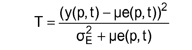
- si y(p,t) - µe(p,t) < εMIN :

expressions dans lesquelles y est la valeur du pixel p, µe est le fond estimé en ce pixel p, σE est un écart-type prédéterminé d'un bruit de mesure, et εMIN est un niveau minimal prédéfini d'une cible à détecter.
- if y (p, t) - μe (p, t) ≥ε MIN :
- if y (p, t) - μe (p, t) <ε MIN :
expressions in which y is the value of the pixel p, μe is the estimated background in this pixel p, σ E is a predetermined standard deviation of a measurement noise, and ε MIN is a predefined minimum level of a target to be detected.
De préférence, lorsque la détection utilise un nombre M d'images de détection, la fonction de test T s'exprime sous la forme suivante :
- si ym(p,t) - µe(p,t) ≥ εMIN :

- si ym(p,t) - µe(p,t) < εMIN:

expressions dans lesquelles Δt est la période d'acquisition entre des images de détection, et ym est la valeur moyenne des pixels p des M images de détection.
- if ym (p, t) - μe (p, t) ≥ ε MIN :
- if ym (p, t) - μe (p, t) <ε MIN :
expressions in which Δt is the acquisition period between detection images, and ym is the average value of the pixels p of the M detection images.
De préférence, l'étape d'estimation du fond et d'estimation des caractéristiques statistiques de l'erreur d'estimation du fond met en oeuvre un filtre de Kalman prenant en compte un modèle d'évolution du fond de l'image de détection.Preferably, the step of estimating the background and estimating the statistical characteristics of the bottom estimation error uses a Kalman filter taking into account a pattern of evolution of the background of the detection image. .
De préférence, le modèle d'évolution du fond de l'au moins une image de détection comporte une composante d'évolution spatiale et une composante d'évolution temporelle.Preferably, the bottom evolution model of the at least one detection image comprises a spatial evolution component and a temporal evolution component.
De préférence, la composante d'évolution spatiale et la composante d'évolution temporelle sont modélisées, pour un pixel à évaluer, par des lois normales de moyennes nulles et d'écart-types respectifs déterminés en fonction des valeurs de pixels d'un groupe de pixels autour du pixel à évaluer.Preferably, the spatial evolution component and the temporal evolution component are modeled, for a pixel to be evaluated, by normal laws of zero means and respective standard deviations determined as a function of the pixel values of a group. pixels around the pixel to be evaluated.
De préférence, le fond d'une image de détection est estimé en fonction d'au moins une image, dite « image d'estimation », chaque image d'estimation étant acquise préalablement à l'image de détection et étant séparée de ladite image de détection par un délai non nul, égal ou supérieur à un temps prédéfini d'apparition d'une cible. De telles dispositions permettent de mieux estimer le fond, en assurant qu'aucune cible n'est présente dans les images d'estimation.Preferably, the background of a detection image is estimated as a function of at least one image, called the "estimation image", each estimation image being acquired prior to the detection image and being separated from said image detection by a non-zero delay equal to or greater than a predefined time of appearance of a target. Such provisions make it possible to better estimate the background, by ensuring that no target is present in the estimation images.
De préférence, on détermine au moins deux seuils pour chaque pixel à évaluer, et dans lequel la valeur d'un premier seuil en ce pixel est déterminée de sorte à assurer que la probabilité de fausse alarme en ce pixel est théoriquement égale ou inférieure à une première valeur prédéfinie, et la valeur d'un second seuil en ce pixel est déterminée de sorte à assurer que la probabilité de détection en ce pixel est théoriquement égale ou supérieure à une seconde valeur prédéfinie.Preferably, at least two thresholds are determined for each pixel to be evaluated, and in which the value of a first threshold in this pixel is determined so as to ensure that the probability of false alarm in this pixel is theoretically equal to or less than one. first predefined value, and the value a second threshold in this pixel is determined so as to ensure that the detection probability in this pixel is theoretically equal to or greater than a second predefined value.
La description suivante de modes de mise en oeuvre de l'invention est faite en se référant aux figures, dans lesquelles des références identiques désignent des éléments identiques ou analogues, qui représentent de manière non limitative :
-
Figure 1 : un diagramme représentant schématiquement les étapes principales d'un procédé de détection de cibles selon l'invention, -
Figures 2, 3 et4 : des diagrammes représentant schématiquement des modes particuliers de mise en oeuvre du procédé de détection, -
Figure 5 : un exemple d'évolution temporelle de la valeur d'un pixel d'une image, au cours de l'apparition d'une cible dans ledit pixel.
-
Figure 1 : a diagram schematically showing the main steps of a target detection method according to the invention, -
Figures 2, 3 and4 diagrams schematically showing particular modes of implementation of the detection method, -
Figure 5 : an example of temporal evolution of the value of a pixel of an image, during the appearance of a target in said pixel.
La présente invention concerne un procédé de détection de cibles dans une image, dite « image de détection », acquise par un capteur embarqué dans un véhicule survolant un corps céleste, de préférence la Terre.The present invention relates to a method for detecting targets in an image, called a "detection image", acquired by a sensor embedded in a vehicle flying over a celestial body, preferably the Earth.
Dans le contexte de l'invention, une image est préférentiellement une image bidimensionnelle, constituée par exemple d'une matrice de pixels. Chaque pixel représente une portion d'une scène observée depuis le véhicule survolant la Terre. Une scène observée correspond à une zone à la surface de la Terre, dont certaines parties sont occultées, notamment par des nuages.In the context of the invention, an image is preferably a two-dimensional image, constituted for example by a matrix of pixels. Each pixel represents a portion of a scene observed from the vehicle flying over the Earth. An observed scene corresponds to an area on the surface of the Earth, some parts of which are obscured, notably by clouds.
Le capteur est de préférence un capteur optique. Par exemple, il s'agit d'un capteur qui mesure le rayonnement de la scène observée dans le domaine des longueurs d'ondes infrarouges.The sensor is preferably an optical sensor. For example, it is a sensor that measures the radiation of the scene observed in the infrared wavelengths domain.
Le véhicule, embarquant le capteur optique, peut être de tout type adapté à l'acquisition d'images successives d'une même scène observée. Par exemple, le véhicule est un satellite en orbite autour de la Terre, de préférence une orbite géostationnaire. Suivant un autre exemple non limitatif, le véhicule est un aéronef, tel qu'un hélicoptère.The vehicle, embedding the optical sensor, can be of any type adapted to the acquisition of successive images of the same scene observed. For example, the vehicle is a satellite orbiting the Earth, preferably a geostationary orbit. According to another non-limiting example, the vehicle is an aircraft, such as a helicopter.
Par « cible », on entend de manière générale tout événement modifiant le fond de l'image. Le fond de l'image correspond à la partie essentiellement statique de la scène observée, c'est-à-dire dont les variations sont lentes par rapport au temps d'apparition d'une cible (qui dépend du type de cible considéré). La présente invention trouve une application avantageuse dans la détection de cibles du type engin aérien, par exemple un aéronef (avion, hélicoptère) ou un missile en phase propulsée.By "target" is generally meant any event modifying the background of the image. The background of the image corresponds to the essentially static part of the observed scene, that is to say whose variations are slow compared to the time of appearance of a target (which depends on the type of target considered). The present invention finds an advantageous application in the detection of targets of the air-craft type, for example an aircraft (airplane, helicopter) or a propelled phase missile.
La mise en oeuvre du procédé de détection de cibles selon l'invention est par exemple assurée par un dispositif de calcul (microcontrôleur, ordinateur muni d'un microprocesseur, etc.). Le dispositif de calcul comporte des moyens de mémorisation (disque dur magnétique, mémoire flash, disque optique, etc.) dans lesquels est mémorisé un produit programme d'ordinateur, sous la forme d'un ensemble d'instructions de code de programme à exécuter pour mettre en oeuvre les étapes du procédé selon l'invention, ainsi que des images acquises par le capteur optique. Suivant certains modes de réalisation, le dispositif de calcul comporte également des circuits intégrés spécialisés, de type ASIC, FPGA, etc., adaptés à mettre en oeuvre tout ou partie des étapes d'un ou des procédés selon l'invention.The implementation of the target detection method according to the invention is for example provided by a computing device (microcontroller, computer equipped with a microprocessor, etc.). The computing device includes storage means (magnetic hard disk, flash memory, optical disk, etc.) in which a computer program product is stored in the form of a set of program code instructions to be executed. to implement the steps of the method according to the invention, as well as images acquired by the optical sensor. According to some embodiments, the computing device also comprises specialized integrated circuits, of the ASIC, FPGA, etc. type, adapted to implement all or part of the steps of one or more methods according to the invention.
Le dispositif de calcul est de préférence embarqué avec le capteur optique dans le véhicule survolant la Terre dans le cas d'un traitement en temps réel, adapté par exemple à la détection de missiles balistiques. Dans le cas d'un traitement en temps différé, le dispositif de calcul est embarqué avec le capteur optique dans le véhicule, ou bien il est déporté, c'est-à-dire localisé dans une station terrestre ou dans un second véhicule survolant la Terre.The computing device is preferably embedded with the optical sensor in the vehicle flying over the Earth in the case of a real-time processing, adapted for example to the detection of ballistic missiles. In the case of a delayed time processing, the computing device is embedded with the optical sensor in the vehicle, or it is deported, that is to say located in a ground station or in a second vehicle flying over the Earth.
Les définitions et notations utilisées dans la suite de la description sont données ci-après. On comprend que le choix d'une convention particulière n'est pas limitatif de l'invention qui pourrait être décrite de manière équivalente en adoptant d'autres conventions sans que l'invention en soit modifiée.The definitions and notations used in the remainder of the description are given below. It is understood that the choice of a particular convention is not limiting of the invention which could be described in an equivalent manner by adopting other conventions without the invention being modified.
Une image acquise à un instant t est désignée par y(t). L'image y(t) est constituée d'une pluralité de pixels, dont les valeurs sont désignées par y(p,t), où p désigne l'indice d'un pixel de l'image. Par exemple, p est compris entre 1 et NLxNc, où NL désigne le nombre de lignes de pixels de l'image y(t) et Nc désigne le nombre de colonnes de ladite image.An image acquired at a time t is designated by y (t). The image y (t) consists of a plurality of pixels, whose values are designated y (p, t), where p denotes the index of a pixel of the image. For example, p is between 1 and N L xN c , where N L denotes the number of pixel lines of the image y (t) and N c denotes the number of columns of said image.
Un pixel y(p,t) correspond principalement à un signal x(p,t) du rayonnement mesuré de la portion de la scène observée, perturbé par un bruit b(p,t) : ![]()
![]()
En l'absence de cible dans le pixel d'indice p, le signal x(p,t) est égal au fond de la scène observée, désigné par µ(p,t). Si une cible est présente, le signal x(p,t) peut être exprimé comme suit : ![]()
où c(p,t) est le signal mesuré correspondant au rayonnement de la cible.In the absence of a target in the pixel of index p, the signal x (p, t) is equal to the background of the observed scene, designated by μ (p, t). If a target is present, the signal x (p, t) can be expressed as follows: ![]()
where c (p, t) is the measured signal corresponding to the radiation of the target.
Le bruit b(p,t) a diverses origines. En particulier, il peut être modélisé comme étant la somme d'un bruit bE(p,t) d'origine électronique, et un bruit bp(p,t) d'origine photonique.The noise b (p, t) has various origins. In particular, it can be modeled as the sum of a noise b E (p, t) of electronic origin, and a noise b p (p, t) of photonic origin.
Le bruit électronique bE(p,t) représente un bruit de mesure du capteur optique. Le bruit électronique est généralement modélisé par une variable aléatoire BE(p,t) gaussienne, qui suit une loi de probabilités Normale N(0,σ2 E), da valeur moyenne nulle et d'écart-type σE indépendant de la scène observée.The electronic noise b E (p, t) represents a measurement noise of the optical sensor. The electronic noise is generally modeled by a random variable B E (p, t) Gaussian, which follows a law of probabilities Normal N (0, σ 2 E ), da zero mean value and standard deviation σ E independent of the scene observed.
Le bruit photonique bp(p,t) tient compte du caractère aléatoire de la mesure du nombre de photons. Le bruit photonique est généralement modélisé par une variable aléatoire Bp(p,t) qui suit une loi de probabilités de Poisson. Etant donné le nombre important de photons reçus, et en application de la loi des grands nombres, cette loi de probabilité est parfois approchée par une loi Normale N(O,x(p,t)) de valeur moyenne nulle et de variance x(p,t).The photon noise b p (p, t) takes into account the random nature of the measurement of the number of photons. Photon noise is usually modeled by a random variable B p (p, t) that follows a Poisson probability law. Given the large number of photons received, and in application of the law of large numbers, this probability law is sometimes approximated by a normal law N (O, x (p, t)) of mean value zero and variance x ( p, t).
En modélisant le bruit photonique par une variable aléatoire gaussienne, et en considérant les réalisations du bruit électronique et du bruit photonique comme indépendantes, le bruit b(p,t) peut être modélisé par une variable aléatoire B(p,t) gaussienne : ![]()
![]()
De manière plus générale, on peut considérer d'autres sources d'erreurs, par exemple liées aux erreurs résiduelles de calibration de biais et de gain, désignées respectivement par aB(p) et par aG(p), qui varient peu au cours du temps, mais qui peuvent être différentes d'un pixel à un autre. Dans ce cas, l'expression de la valeur y(p,t) du pixel d'indice p peut s'exprimer sous la forme suivante : ![]()
où le bruit b(p,t) peut être modélisé par une variable aléatoire gaussienne : 
![]()
where the noise b (p, t) can be modeled by a Gaussian random variable:
En pratique, les erreurs de calibration aB(p) et aG(p) peuvent être estimées en tout pixel en mettant en oeuvre des procédés connus de l'homme de l'art. A des fins de clarté de la description, mais à titre nullement limitatif de l'invention, on considère dans la suite de la description que aB(p) est égal à zéro et que aG(p) est égal à un. Les équations données ci-après peuvent être généralisées à des valeurs quelconques de aB(p) et de aG(p), en partant des équations (4) et (5).In practice, the calibration errors a B (p) and a G (p) can be estimated in any pixel by implementing methods known to those skilled in the art. For the sake of clarity of the description, but by no means limiting of the invention, it is considered in the remainder of the description that B (p) is equal to zero and that G (p) is equal to one. The equations given below can be generalized to arbitrary values of a B (p) and a G (p), starting from equations (4) and (5).
La
Le procédé de détection de cibles comporte principalement une étape 10 d'estimation du fond de l'image de détection, une étape 20 de détermination de seuil pour chaque pixel à évaluer, et une étape 30 d'évaluation d'un test de détection par rapport aux seuils déterminés, en chaque pixel à évaluer de l'image de détection.The target detection method mainly comprises a step of estimating the background of the detection image, a threshold determination step for each pixel to be evaluated, and a step of evaluating a detection test by relative to the determined thresholds, in each pixel to be evaluated of the detection image.
Par « à évaluer », on entend que la détection de cibles peut être restreinte à un sous-ensemble de pixels d'une image de détection, ou qu'au contraire la détection peut être effectuée sur toute l'image de détection. Par exemple, dans le cas d'une détection de missile en phase propulsée, on peut limiter l'évaluation du test de détection à un sous-ensemble de pixels représentant une zone autour d'une base de tir de missiles.By "to be evaluated" is meant that the detection of targets may be restricted to a subset of pixels of a detection image, or that, on the contrary, the detection may be carried out over the entire detection image. For example, in the case of a propelled phase missile detection, the evaluation of the detection test can be limited to a subset of pixels representing an area around a missile firing base.
Il est à noter que l'ordre d'exécution des différentes étapes du procédé de détection n'est pas limitatif de l'invention, et qu'un ordre particulier ne constitue qu'une variante d'implémentation du procédé de détection.It should be noted that the order of execution of the different steps of the detection method is not limiting of the invention, and that a particular order constitutes only a variant of implementation of the detection method.
On note toutefois que, pour un pixel donné, le fond dudit pixel doit être estimé (étape 10) avant de déterminer la valeur du seuil associé (étape 20), seuil qui doit être déterminé avant d'évaluer le test de détection (étape 30) pour ledit pixel donné.However, it should be noted that, for a given pixel, the bottom of said pixel must be estimated (step 10) before determining the value of the associated threshold (step 20), which threshold must be determined before evaluating the detection test (step 30). ) for said given pixel.
Lorsque l'on considère tous les pixels à évaluer, il est possible par exemple d'estimer le fond de l'image de détection pour tous les pixels à évaluer, de déterminer tous les seuils associés, puis d'évaluer le test de détection pour tous les pixels à évaluer. Suivant un autre exemple, les étapes 10 d'estimation, 20 de détermination et 30 d'évaluation sont exécutées successivement pour chaque pixel à évaluer. Suivant encore un autre exemple, l'étape 10 d'estimation est exécutée pour tous les pixels à évaluer, puis les étapes 20 de détermination de seuil et 30 d'évaluation de test de détection sont exécutées successivement pour chaque pixel à évaluer.When considering all the pixels to be evaluated, it is possible, for example, to estimate the background of the detection image for all the pixels to be evaluated, to determine all the associated thresholds, and then to evaluate the detection test for all the pixels to evaluate. In another example, the estimation, determination and evaluation steps are performed. successively for each pixel to be evaluated. In yet another example, the estimation step is performed for all the pixels to be evaluated, and then the threshold determination and detection test evaluation steps are performed successively for each pixel to be evaluated.
Il est à noter que le procédé de détection peut comporter d'autres étapes, comme par exemple une étape préalable, dite « de registration », au cours de laquelle les images acquises sont recalées les unes par rapport aux autres, pour compenser des décalages introduits par les mouvements parasites de la ligne de visée du capteur optique au cours de l'acquisition. L'étape de registration, non représentée sur les figures, peut être mise en oeuvre selon tout procédé de registration connu de l'homme de l'art.It should be noted that the detection method may comprise other steps, such as for example a preliminary step, called "registration", during which the images acquired are recalibrated with respect to each other, to compensate for shifts introduced. by the parasitic movements of the line of sight of the optical sensor during the acquisition. The registration step, not shown in the figures, can be implemented according to any registration method known to those skilled in the art.
Tel que représenté sur la
Il est à noter que les étapes du procédé peuvent, lorsqu'elles sont récurrentes, avoir des périodicités différentes. En particulier, l'évaluation du test de détection (étape 30) se fait de préférence à chaque nouvelle image de détection, tandis que l'estimation du fond (étape 10) peut se faire à chaque nouvelle image de détection, ou toutes les deux, trois ou plus images de détection, suivant la vitesse de variation de la scène observée.It should be noted that the steps of the method may, when they are recurrent, have different periodicities. In particular, the evaluation of the detection test (step 30) preferably takes place with each new detection image, while the estimation of the background (step 10) can be done with each new detection image, or both. , three or more detection images, depending on the speed of variation of the observed scene.
Tel que décrit précédemment, le fond de l'image de détection correspond à la partie de la scène observée dont les variations sont lentes par rapport au temps prédéfini d'apparition d'une cible. L'étape 10 vise à calculer une estimation µe(p,t) du fond µ(p,t) pour chaque pixel à évaluer.As described above, the background of the detection image corresponds to the part of the observed scene whose variations are slow with respect to the predefined time of appearance of a target.
Dans un mode préféré de mise en oeuvre de l'étape 10, le fond de l'image de détection est estimé d'après une image, ou une séquence d'images, dites « images d'estimation », acquises à différents instants dans le temps.In a preferred embodiment of
Les images d'estimation représentent sensiblement la même scène observée que l'image de détection, et sont acquises par un capteur se trouvant dans le plan focal du capteur optique ayant servi à acquérir l'image de détection. De préférence, lesdites images d'estimation sont acquises par le même capteur optique que celui ayant servi à acquérir l'image de détection.The estimation images represent substantially the same observed scene as the detection image, and are acquired by a sensor located in the focal plane of the optical sensor used to acquire the image of detection. Preferably, said estimation images are acquired by the same optical sensor as that used to acquire the detection image.
Rien n'exclut que l'image de détection soit également une image d'estimation, c'est-à-dire que l'image de détection soit également utilisée au cours de l'étape 10 pour estimer son propre fond.Nothing excludes that the detection image is also an estimation image, that is to say that the detection image is also used in
Dans un mode préféré de mise en oeuvre du procédé de détection, illustré sur la
De préférence, les images d'estimation sont séparées dans le temps de l'image de détection courante par un délai non nul, égal ou supérieur au temps d'apparition δ d'une cible.Preferably, the estimation images are separated in time from the current detection image by a non-zero delay equal to or greater than the appearance time δ of a target.
En pratique, l'apparition de la cible dans un ou plusieurs pixels d'une image est progressive, tel qu'illustré par la
Dans la
Les images acquises au cours de l'intervalle I1 ne comportent pas de cible, les images acquises au cours de l'intervalle I3 comportent une cible, et l'intervalle I2 correspond à un intervalle de transition, au cours duquel la cible apparaît, de durée égale à δ.The images acquired during the interval I 1 do not include a target, the images acquired during the interval I 3 comprise a target, and the interval I 2 corresponds to a transition interval, during which the target appears, of duration equal to δ.
On comprend qu'il est avantageux d'estimer le fond de l'image de détection à partir d'images dans lesquelles il n'y a pas de cible présente, c'est-à-dire principalement en fonction d'images acquises au cours de l'intervalle I1.It is understood that it is advantageous to estimate the background of the detection image from images in which there is no present target, that is to say mainly according to images acquired at the course of the interval I 1 .
Si on considère des images d'estimation acquises à des instants antérieurs d'au moins la durée δ à celui d'acquisition de l'image de détection courante, et si on n'a pas détecté de cible dans des images de détection acquises antérieurement au cours de l'intervalle de durée δ, on assure théoriquement que l'estimation du fond est obtenue à partir d'images d'estimation dans lesquelles il n'y a ni cible présente, ni cible en cours d'apparition.If we consider estimation images acquired at previous instants of at least the duration δ to that of acquisition of the current detection image, and if no target has been detected in detection images acquired previously during the interval of duration δ, it is theoretically ensured that the estimation of the bottom is obtained from estimation images in which there is neither present target nor target in progress appearance.
En pratique, le temps d'apparition δ est par exemple préalablement défini comme étant le temps d'apparition d'une cible de référence au-dessus d'un nuage, une cible de référence étant une cible dont on connaît les caractéristiques (ergol utilisé, trajectoire en phase propulsée, etc.). Le temps d'apparition δ est par exemple de l'ordre de quelques centaines de millisecondes à quelques secondes.In practice, the time of appearance δ is for example previously defined as being the time of appearance of a reference target over a cloud, a reference target being a target whose characteristics are known (ergol used , propulsed phase trajectory, etc.). The time of appearance δ is for example of the order of a few hundred milliseconds to a few seconds.
De préférence, tel qu'illustré par la
Par exemple, tel que représenté sur la
La
Au cours de la première phase, les étapes principales du procédé de détection, l'étape 10 d'estimation, l'étape 20 de détermination de seuils et l'étape 30 d'évaluation du test de détection, sont exécutées tant qu'une cible n'a pas été détectée.During the first phase, the main steps of the detection method, the estimation step, the step of determining thresholds and the evaluation step of the detection test, are performed as long as target was not detected.
Lorsqu'une cible a été détectée dans une image de détection, la seconde phase consiste principalement à assurer le suivi d'une cible détectée. La différence principale entre la première et la seconde phase réside dans le fait que l'étape 10 d'estimation du fond n'est plus exécutée, afin d'éviter d'estimer le fond sur des images susceptibles de comporter une cible. Par exemple, on utilise la même estimation du fond que celle utilisée lorsque la cible a été détectée.When a target has been detected in a detection image, the second phase consists mainly of tracking a detected target. The main difference between the first and the second phase lies in the fact that the
De préférence, et tel que représenté sur la
Si au cours de la seconde phase, la cible n'est plus détectée, le procédé de détection s'arrête ou rebascule sur la première phase.If during the second phase, the target is no longer detected, the detection process stops or returns to the first phase.
Suivant un mode préféré de mise en oeuvre du procédé de détection, non illustré par les figures, on estime également, au cours de l'étape 10 d'estimation, des caractéristiques statistiques de l'erreur d'estimation du fond. Suivant un premier exemple, on estime l'écart-type de l'erreur en chaque pixel, désigné par σEST(p,t). Suivant un autre exemple non limitatif, on estime une fonction représentative de la densité de probabilité de l'erreur d'estimation du fond.According to a preferred embodiment of the detection method, not illustrated by the figures, it is also estimated, in the
L'étape 10 d'estimation s'appuie de préférence sur un modèle d'évolution du fond de l'image, de préférence un modèle Markovien, par exemple d'ordre 1, en chaque pixel d'indice p : ![]()
expression dans laquelle :
- Δt est la période d'acquisition entre deux images consécutives d'une séquence d'images ; on considère, à titre nullement limitatif de l'invention, que la période d'acquisition est sensiblement constante,
- w(p,t) est un terme d'évolution, modélisé par une variable aléatoire gaussienne de moyenne nulle et d'écart-type σEVOL(p,t).
expression in which:
- Δt is the acquisition period between two consecutive images of a sequence of images; it is considered, by way of no limitation of the invention, that the acquisition period is substantially constant,
- w (p, t) is an evolution term, modeled by a Gaussian random variable of zero mean and standard deviation σ EVOL (p, t).
Il est connu, en particulier de la publication scientifique précitée « Detecting small moving objects using temporal hypothesis testing », des auteurs
De manière plus générale, d'autres modèles d'évolution peuvent être considérés, et le choix d'un modèle particulier ne constitue qu'une variante d'implémentation de l'invention.More generally, other evolution models can be considered, and the choice of a particular model is only one variant of implementation of the invention.
A partir du modèle d'évolution choisi, on utilise un estimateur qui fournit à la fois une estimation µe(p,t) du fond µ(p,t) de l'image de détection, et une estimation des caractéristiques de l'erreur d'estimation, par exemple une estimation σeEST(p,t) de l'écart-type de l'erreur d'estimation σEST(p,t) ou une fonction représentative de la densité de probabilité de l'erreur d'estimation.From the evolution model chosen, we use an estimator that provides both an estimate μe (p, t) of the bottom μ (p, t) of the detection image, and an estimate of the characteristics of the error. estimation, for example an estimate σe EST (p, t) of the standard deviation of the estimation error σ EST (p, t) or a function representative of the probability density of the estimation error.
Un estimateur du type filtrage de Kalman est particulièrement adapté au cas d'un modèle Markovien d'évolution temporelle du fond. Un tel estimateur peut prendre en compte plusieurs images d'estimation et fournir une estimation du fond et, le cas échéant, une estimation des caractéristiques de l'erreur d'estimation.An estimator of the Kalman filtering type is particularly adapted to the case of a Markovian model of temporal evolution of the background. Such an estimator can take into account several estimation images and provide an estimate of the background and, where appropriate, an estimate of the characteristics of the estimation error.
De préférence, l'estimation est faite au moyen d'un filtre de Kalman du type « sans odeur » (« Unscented Kalman Filter » ou UKF dans la littérature anglo-saxonne). Un tel filtre de Kalman sans odeur est connu par exemple du livre « The Unscented Kalman Filter », des auteurs E. Wan et R.V. der Merwe, publié aux éditions Wiley.Preferably, the estimate is made by means of a Kalman filter of the "odorless" type ("Unscented Kalman Filter" or UKF in the English literature). Such an odorless Kalman filter is known for example from the book "The Unscented Kalman Filter", by E. Wan and R.V. der Merwe, published by Wiley.
De manière plus générale, l'étape 10 d'estimation peut mettre en oeuvre tout procédé d'estimation du fond d'images et, le cas échéant, d'estimation du bruit d'estimation, connu de l'homme de l'art.More generally, the
Selon l'invention, on définit une pluralité de seuils η(p,t), au moins un seuil par pixel, dont la valeur est déterminée en fonction de l'estimation µe(p,t) du fond p(p,t) de l'image de détection.According to the invention, a plurality of thresholds η (p, t), at least one threshold per pixel, whose value is determined as a function of the estimate μe (p, t) of the background p (p, t), are defined. of the detection image.
Au cours de l'étape 30 d'évaluation, on évalue un test de détection en chaque pixel à évaluer, test de détection qui dépend du fond estimé pour le pixel évalué.During the evaluation step, a detection test is evaluated at each pixel to be evaluated, a detection test that depends on the estimated background for the evaluated pixel.
Le test de détection est de préférence un test statistique d'hypothèses de type Neyman-Pearson, ou son extension sous forme de rapport de vraisemblance généralisée, dans lequel on considère au moins deux hypothèses H0(p,t) et H1(p,t) :
- H0(p,t) : il n'y a pas de cible à l'instant t dans le pixel d'indice p,
- H1(p,t): une cible est présente à l'instant t dans le pixel d'indice p.
- H 0 (p, t): there is no target at time t in the pixel of index p,
- H 1 (p, t): a target is present at time t in the pixel of index p.
Un test de détection du type test statistique d'hypothèses est généralement basé sur le choix d'une fonction de test, appelée fonction T dans la suite de l'exposé, construite à partir des mesures effectuées. L'évaluation du test de détection revient à calculer la valeur de la fonction de test T à partir des mesures considérées, et à comparer ladite valeur à un seuil. Suivant un exemple non limitatif, l'hypothèse H0(p,t) est vérifiée si la valeur de la fonction de test T est inférieure au seuil, et l'hypothèse H1(p,t) est vérifiée si la valeur de la fonction de test T est supérieure au seuil.A test of the hypothesis test type test is generally based on the choice of a test function, called T function in the rest of the presentation, built from the measurements made. The evaluation of the detection test amounts to calculating the value of the test function T from the measurements considered, and comparing said value with a threshold. Following a non-limiting example, the hypothesis H 0 (p, t) is verified if the value of the test function T is lower than the threshold, and the hypothesis H 1 (p, t) is verified if the value of the function of T test is greater than the threshold.
Le calcul du seuil dépend avantageusement du test de détection. Plus particulièrement, il dépend de la fonction T de test choisie.The calculation of the threshold advantageously depends on the detection test. More particularly, it depends on the test function T selected.
D'un point de vue théorique, il est possible de définir un test de détection optimal, dit « test du rapport de vraisemblance généralisée », à partir d'un modèle du signal y(p,t) mesuré. Ce type de test est supposé connu de l'homme de l'art, et sa formulation théorique n'est pas rappelée.From a theoretical point of view, it is possible to define an optimal detection test, called "generalized likelihood ratio test", from a model of the signal y (p, t) measured. This type of test is assumed to be known to those skilled in the art, and its theoretical formulation is not recalled.
Toutefois, la mise en oeuvre du test du rapport de vraisemblance généralisée est difficile en pratique, du fait d'une complexité analytique élevée, qui est incompatible avec les capacités de calcul actuelles, en particulier les capacités des dispositifs de calcul actuellement embarqués dans des satellites, et/ou avec des contraintes d'évaluation en temps réel ou quasi-réel (en particulier dans le cas d'une détection de missiles balistiques).However, the implementation of the generalized likelihood ratio test is difficult in practice, because of a high analytical complexity, which is incompatible with the current calculation capabilities, in particular the capabilities of the currently embedded computing devices in satellites , and / or with real-time or near real-time evaluation constraints (particularly in the case of ballistic missile detection).
Avantageusement, on considère certaines approximations du test optimal de détection visant à réduire la complexité analytique de son évaluation. On décrit ci-après un exemple non limitatif de test de détection dont la complexité analytique est adaptée aux capacités des dispositifs de calcul actuellement embarqués dans des satellites.Advantageously, certain approximations of the optimal detection test are considered in order to reduce the analytical complexity of its evaluation. A non-limiting example of a detection test whose analytical complexity is adapted to the capabilities of computing devices currently embedded in satellites is described below.
De préférence, le calcul des seuils η(p,t) tient compte de la présence du bruit photonique bp(p,t) dans le signal y(p,t), au moyen d'un modèle de bruit photonique. De manière plus générale, le calcul des seuils η(p,t) peut tenir compte de tout autre type de bruit instationnaire. Dans la suite de la description, on se place, à titre nullement limitatif, dans le cas où un modèle de bruit photonique est effectivement pris en compte.Preferably, the calculation of the thresholds η (p, t) takes into account the presence of the photon noise b p (p, t) in the signal y (p, t), by means of a photonic noise model. More generally, the calculation of the thresholds η (p, t) can take into account any other type of unsteady noise. In the remainder of the description, it is placed, in no way limiting, in the case where a photonic noise model is actually taken into account.
Ledit test de détection est obtenu en considérant tout d'abord une approximation du modèle théorique du bruit photonique (variable aléatoire qui suit une loi de Poisson), qu'on modélise par une variable aléatoire gaussienne N(0,x(p,t)), tel que décrit précédemment.Said detection test is obtained by first considering an approximation of the theoretical model of photonic noise (random variable that follows a Poisson distribution), which is modeled by a Gaussian random variable N (0, x (p, t) ), as previously described.
Compte tenu des modèles choisis pour le bruit électronique et le bruit photonique, la valeur y(p,t) du pixel d'indice p peut être considérée comme la réalisation d'une variable aléatoire Y(p,t) gaussienne : ![]()
où x(p,t) est égal à µ(p,t) en l'absence de cible, à (p(p,t) + c(p,t)) en présence d'une cible. Le test de détection proposé est ensuite obtenu en approchant le test optimal formulé d'après ce modèle de y(p,t).Given the models chosen for the electronic noise and the photonic noise, the value y (p, t) of the pixel of index p can be considered as the realization of a random variable Y (p, t) Gaussian: ![]()
where x (p, t) is equal to μ (p, t) in the absence of a target, to (p (p, t) + c (p, t)) in the presence of a target. The proposed detection test is then obtained by approaching the optimal test formulated from this model of y (p, t).
Le test de détection proposé dépend principalement d'un niveau minimal εMIN du signal c(p,t) qui serait mesuré pour une cible, de l'écart-type σE, et du fond µ(p,t) de l'image de détection.The proposed detection test depends mainly on a minimum level ε MIN of the signal c (p, t) that would be measured for a target, the standard deviation σ E , and the background μ (p, t) of the detection image.
A titre nullement limitatif, on considère que le niveau minimal εMIN et l'écart-type σE sont connus a priori : le niveau minimal εMIN est par exemple prédéterminé en fonction d'une cible de référence correspondant théoriquement à un pire cas pour la détection, et l'écart-type σE est par exemple prédéterminé par calibration du capteur optique.By way of no limitation, we consider that the minimum level ε MIN and the standard deviation σ E are known a priori: the minimum level ε MIN is for example predetermined according to a reference target theoretically corresponding to a worst case for the detection, and the standard deviation σ E is for example predetermined by calibration of the optical sensor.
En pratique, le fond µ(p,t) de l'image de détection est estimé au cours de l'étape 10 d'estimation, qui fournit une estimation µe(p,t) dudit fond, utilisée dans les différents calculs décrits ci-après.In practice, the background μ (p, t) of the detection image is estimated during the
Dans un mode préféré de mise en oeuvre, la fonction T de test optimale au sens précédent peut être approximée comme suit :
- si y(p,t) - µe(p,t) ≥ εMIN:

- si y(p,t) - µe(p,t) < εMIN :

- if y (p, t) - μe (p, t) ≥ ε MIN :
- if y (p, t) - μe (p, t) <ε MIN :
La valeur de la fonction de test T en un pixel donné est en fait la différence des distances de la mesure en ce pixel aux valeurs que cette mesure devrait avoir suivant respectivement les au moins deux hypothèses du test, c'est-à-dire la valeur du fond en ce pixel s'il n'y a pas de cible, et la valeur du fond en ce pixel auquel s'ajoute le signal εMIN de la cible s'il y a une cible. On peut en effet écrire cette fonction de test T comme la différence : ![]()
où la distance D0 pour l'hypothèse H0(p,t) d'absence de cible est donnée par : 
et la distance D1 pour l'hypothèse H1(p,t) de présence de cible est donnée par : 
![]()
where the distance D 0 for the hypothesis H 0 (p, t) of absence of target is given by:
and the distance D 1 for the target presence hypothesis H 1 (p, t) is given by:
Dans cet exemple, la distance est avantageusement quadratique et pondérée par la valeur du signal de manière à tenir compte de la nature en partie photonique du bruit d'acquisition. On comprend que cet exemple n'est pas limitatif de l'invention, et qu'un autre type de distance peut être utilisé.In this example, the distance is advantageously quadratic and weighted by the value of the signal so as to take account of the partly photonic nature of the acquisition noise. It is understood that this example is not limiting of the invention, and that another type of distance can be used.
Considérons un seuil η(p,t) tel que si T(y(p,t),µe(p,t)) est supérieur à ce seuil η(p,t), on conclut que l'hypothèse H1(p,t) est la plus vraisemblable et dans le cas contraire, on conclut que c'est l'hypothèse H0(p,t) qui est la plus vraisemblable.Consider a threshold η (p, t) such that if T (y (p, t), μe (p, t)) is greater than this threshold η (p, t), we conclude that the hypothesis H 1 (p , t) is the most likely and if not, we conclude that it is the hypothesis H 0 (p, t) that is most likely.
Dans le cadre de l'invention, on cherche principalement à maîtriser la probabilité de fausse alarme. Pour déterminer le lien entre le seuil η(p,t) et la probabilité de fausse alarme, on considère la probabilité de franchissement du seuil η(p,t) par la fonction T. La probabilité de franchissement d'un seuil η(p,t) par la fonction T est désignée par h(η(p,t),µe(p,t),x(p,t)).In the context of the invention, the main aim is to control the probability of false alarm. To determine the link between the threshold η (p, t) and the probability of false alarm, we consider the probability of crossing the threshold η (p, t) by the function T. The probability of crossing a threshold η (p , t) by the function T is denoted by h (η (p, t), μe (p, t), x (p, t)).
A des fins de clarté de la description, les paramètres (p,t) sont temporairement omis. La probabilité de franchissement d'un seuil η par la fonction T, désignée par h(η,µe,x) peut alors s'exprimer : ![]()
expression dans laquelle Y est distribué tel que décrit à l'expression (7).For the sake of clarity of description, the parameters (p, t) are temporarily omitted. The probability of crossing a threshold η by the function T, denoted by h (η, μe, x) can then be expressed: ![]()
wherein Y is distributed as described in (7).
En remplaçant la fonction T par les expressions (8) et (9), la probabilité de franchissement d'un seuil η peut s'exprimer de la façon suivante : 


Les expressions de g1(η,µe) et de g2(η,µe) se déduisent de la fonction T de test donnée aux expressions (8) et (9), en constatant que lorsque (y - µe ≥ εMIN), la probabilité d'avoir T(Y,µe) égal ou supérieur à η est égale à : 
et que lorsque (y - µe < εMIN), la probabilité d'avoir T(Y,µe) égal ou supérieur à η est égale à : 
and that when (y - μe <ε MIN ), the probability of having T (Y, μe) equal to or greater than η is equal to:
Or, compte tenu de l'hypothèse (7), la probabilité d'avoir Y supérieur à une valeur p est donnée par : ![]()
où Q est la fonction de répartition d'une Gaussienne, pouvant être exprimée sous la forme suivante : 
![]()
where Q is the distribution function of a Gaussian, which can be expressed in the following form:
En combinant les équations (14) et (19), on obtient : 
La fonction h représente donc la probabilité que la fonction T dépasse un seuil η, lorsque le fond est égal à µe et que le signal est égal à x.The function h therefore represents the probability that the function T exceeds a threshold η, when the background is equal to μe and the signal is equal to x.
On peut considérer que la probabilité de fausse alarme PFA(p,t) en un pixel p et un instant donné t est égale à PFA(p,t) = h(η(p,t),µe(p,t),µ(p,t)), c'est-à-dire la probabilité que le test d'hypothèse déclenche l'alarme (la fonction T de test dépassant le seuil) alors qu'il n'y a pas de cible en ce pixel (x(p,t) = µ(p,t)).We can consider that the probability of false alarm P FA (p, t) in a pixel p and a given moment t is equal to P FA (p, t) = h (η (p, t), μe (p, t ), μ (p, t)), that is, the probability that the hypothesis test triggers the alarm (the test function T exceeds the threshold) while there is no target in this pixel (x (p, t) = μ (p, t)).
Suivant le même principe, la probabilité de détection est donnée par h(η(p,t),µe(p,t),µ(p,t)+c(p,t)) qui est par définition la probabilité d'avoir T(y(p,t), µe(p,t)) supérieur à η(p,t) en présence d'une cible de niveau c(p,t).Following the same principle, the probability of detection is given by h (η (p, t), μe (p, t), μ (p, t) + c (p, t)) which is by definition the probability of have T (y (p, t), μe (p, t)) greater than η (p, t) in the presence of a target of level c (p, t).
Dans un mode préféré de mise en oeuvre du procédé, la valeur du seuil η(p,t) est déterminée de sorte à assurer la maîtrise de la probabilité de fausse alarme au sein d'une même image. Par exemple, les valeurs des différents seuils, calculés pour une même image de détection, sont déterminées de sorte à avoir théoriquement la même probabilité de fausse alarme (égale ou inférieure à une valeur prédéfinie PFA0, par exemple 1%) en tout pixel à évaluer de l'image de détection.In a preferred mode of implementation of the method, the value of the threshold η (p, t) is determined so as to ensure control of the probability of false alarm within the same image. For example, the values of the different thresholds, calculated for the same detection image, are determined so as to theoretically have the same probability of false alarm (equal to or less than a predefined value P FA0 , for example 1%) in any pixel to be evaluated of the detection image.
Au cours de l'étape 20 de détermination du seuil pour le pixel d'indice p de l'image de détection, on détermine par exemple la valeur du seuil η(p,t) pour laquelle la probabilité de fausse alarme est théoriquement égale à une valeur prédéfinie PFA0, ce qui revient à déterminer le seuil η(p,t) qui satisfait l'expression suivante : ![]()
![]()
La valeur du seuil η(p,t) est par exemple calculée en considérant que le fond µ(p,t) et son estimation µe(p,t) sont égaux. Ainsi, en remplaçant µ(p,t) par son estimation µe(p,t) dans l'expression (22), on peut déterminer des valeurs de la fonction h(η(p,t),µe(p,t),µe(p,t)) pour différentes valeurs du seuil η(p,t), et sélectionner le seuil η(p,t) pour lequel la probabilité de fausse alarme PFA0. Lesdites valeurs de la fonction h(η(p,t),µe(p,t),µe(p,t)) sont de préférence préalablement déterminées, pour différentes valeurs de µe(p,t), et mémorisées dans des moyens de mémorisation.The value of the threshold η (p, t) is for example calculated by considering that the bottom μ (p, t) and its estimate μe (p, t) are equal. Thus, by replacing μ (p, t) by its estimate μe (p, t) in the expression (22), we can determine values of the function h (η (p, t), μe (p, t) , μe (p, t)) for different values of the threshold η (p, t), and select the threshold η (p, t) for which the probability of false alarm P FA0 . Said values of the function h (η (p, t), μe (p, t), μe (p, t)) are preferably determined beforehand, for different values of μe (p, t), and stored in means memorisation.
Dans un mode préféré de mise en oeuvre, lorsque l'on a estimé des caractéristiques de l'erreur d'estimation du fond de l'image de détection, celles-ci sont également utilisées pour déterminer les seuils en chaque pixel.In a preferred embodiment, when estimating characteristics of the estimation error of the background of the detection image, these are also used to determine the thresholds at each pixel.
Dans un premier exemple, les caractéristiques de l'erreur d'estimation du fond de l'image sont estimées sous la forme d'une estimation σeEST(p,t) de l'écart-type σEST(p,t) de l'erreur d'estimation du fond, et le seuil η(p,t) est déterminé comme étant égal à η(p,t) = h-1(PFA0, µr(p,t), µr(p,t)). Dans cette expression, µr(p,t) est un fond utilisé en remplacement de l'estimation µe(p,t), déterminé en fonction notamment de ladite estimation µe(p,t) dudit fond et de l'estimation σeEST(p,t) de l'écart-type de l'erreur d'estimation du fond. De préférence, le fond de remplacement µr(p,t) est une surestimation du fond, obtenue en ajoutant à µe(p,t) une valeur représentative de l'erreur d'estimation du fond. Avantageusement, on prendra µr(p,t) égal à (µe(p,t) + k·σeEST(p,t)), où k est un paramètre positif ou nul prédéfini. De préférence, on prend k égal à deux ou trois. Le paramètre k peut être choisi pour contrôler et limiter le taux de pixels pour lesquels la probabilité de fausse alarme observée sera supérieure à la valeur prédéfinie PFA0. Par exemple, dans le cas d'une surestimation du fond par k·σeEST(p,t), avec k égal à trois, la probabilité de fausse alarme sera inférieure à PFA0 pour 99% des pixels.In a first example, the characteristics of the estimation error of the background of the image are estimated in the form of an estimate σe EST (p, t) of the standard deviation σ EST (p, t) of the bottom of the estimation error, and the threshold η (p, t) is determined to be equal to η (p, t) = h -1 (P FA0, ÁR (p, t), ÁR (p, t )). In this expression, μr (p, t) is a background used as a replacement for the estimate μe (p, t), determined as a function in particular of the said estimate μe (p, t) of the background and the estimate σe EST ( p, t) of the standard deviation of the bottom estimation error. Preferably, the replacement background μr (p, t) is an overestimate of the background, obtained by adding to μe (p, t) a value representative of the estimation error of the background. Advantageously, we will take μr (p, t) equal to (μe (p, t) + k · σe EST (p, t)), where k is a predefined positive or null parameter. Preferably, we take k equal to two or three. The parameter k can be chosen to control and limit the rate of pixels for which the probability of false alarm observed will be greater than the predefined value P FA0 . For example, in the case of overestimation of the merits by k · σe EST (p, t), with k equal to three, the probability of false alarm will be less than P FA0 for 99% of the pixels.
Dans un second exemple, les caractéristiques de l'erreur d'estimation du fond de l'image sont estimées sous la forme d'une fonction représentative de la densité de probabilité de ladite erreur d'estimation.In a second example, the characteristics of the estimation error of the background of the image are estimated in the form of a function representative of the probability density of said estimation error.
On peut par exemple considérer que l'erreur d'estimation suit une loi Normale N(0,σ2 EST(p,t)), qu'on approche par une loi Normale N(0,σe2 EST(p,t)) après avoir déterminé une estimation σeEST(p,t) de l'écart-type σEST(p,t) de l'erreur d'estimation du fond. Cette loi peut être intégrée dans le calcul de la probabilité de fausse alarme PFA(p,t), en considérant que le fond µ(p,t) est la réalisation d'une variable aléatoire M(p,t) distribuée suivant une loi normale N(µe(p,t), σe2 EST(p,t)).For example, we can consider that the estimation error follows a Normal distribution N (0, σ 2 EST (p, t)), which is approached by a Normal distribution N (0, σe 2 EST (p, t) ) after determining an estimate σe EST (p, t) of the standard deviation σ EST (p, t) of the bottom estimation error. This law can be integrated in the calculation of the probability of false alarm P FA (p, t), considering that the bottom μ (p, t) is the realization of a random variable M (p, t) distributed according to a normal law N (μe (p, t), σe 2 EST (p, t)).
Dans ce cas, la probabilité de fausse alarme PFA(p,t) sera donnée par la valeur de la fonction k(η(p,t),µe(P,t),σeEST(p,t)) égale par définition à : ![]()
![]()
La fonction k peut s'exprimer sous la forme : 
L'intégrale de l'expression (24) n'est pas calculable analytiquement, mais peut être approchée en utilisant toute technique d'intégration numérique connue de l'homme de l'art. Suivant un exemple non limitatif, cette intégrale est approchée en mettant en oeuvre une technique classique de Monte Carlo par pondération de vraisemblance. Pour des valeurs de µe(p,t) et σeEST(p,t) données, on génère un nombre Ne d'échantillons µi (typiquement de l'ordre de 10000 échantillons) suivant la loi Normale N(µe(p,t), f2.σe2 EST(p,t)) où f est un facteur d'amplification de σeEST(p,t) permettant, de manière connue, d'améliorer l'approximation de l'intégrale. Ladite intégrale peut ensuite être approximée comme suit : 
expression dans laquelle : 
expression in which:
Comme précédemment, on peut déterminer des valeurs de la fonction k(η(p,t),µe(p,t),σeEST(p,t)) pour différentes valeurs du seuil η(p,t), et sélectionner le seuil η(p,t) pour lequel on obtient une probabilité de fausse alarme sensiblement égale à PFA0. Lesdites valeurs de la fonction k(η(p,t),µe(P,t),σeEST(p,t)) sont de préférence préalablement déterminées, pour différentes valeurs de µe(p,t) et de σeEST(p,t), et mémorisées dans des moyens de mémorisation.As previously, one can determine values of the function k (η (p, t), μe (p, t), σe EST (p, t)) for different values of the threshold η (p, t), and select the threshold η (p, t) for which we obtain a probability of false alarm substantially equal to P FA0 . Said values of the function k (η (p, t), μe ( P , t), σe EST (p, t)) are preferably determined beforehand, for different values of μe (p, t) and σe EST ( p, t), and stored in storage means.
Pour estimer des probabilités de fausse alarme autour de 1%, on considère de préférence une valeur de f comprise entre deux et dix.To estimate probabilities of false alarm around 1%, a value of f between two and ten is preferably considered.
On comprend donc qu'en estimant des caractéristiques de l'erreur d'estimation et en déterminant les seuils en fonction des caractéristiques estimées, il sera possible de mieux maîtriser la probabilité de fausse alarme. Par exemple, les seuils sont déterminés de sorte que la probabilité de fausse alarme est théoriquement la même en chaque pixel à évaluer, ou de sorte que la probabilité de fausse alarme est théoriquement inférieure à une valeur prédéfinie en chaque pixel à évaluer.It is thus understood that by estimating characteristics of the estimation error and by determining the thresholds according to the estimated characteristics, it will be possible to better control the probability of false alarm. For example, the thresholds are determined so that the probability of false alarm is theoretically the same in each pixel to be evaluated, or so that the probability of false alarm is theoretically less than a predefined value in each pixel to be evaluated.
De manière plus générale, on peut utiliser, au cours de l'étape 30 d'évaluation du test de détection, une pluralité de mesures, c'est-à-dire une pluralité d'images de détection, que l'on aura pris soin de recaler les unes par rapport aux autres, pour compenser des décalages introduits par les mouvements parasites de la ligne de visée du capteur optique au cours de l'acquisition. Dans la suite du paragraphe, on suppose que cette étape de registration est effectuée au préalable.More generally, during the detection test evaluation step, a plurality of measurements, i.e., a plurality of detection images, can be used. recalibration relative to each other, to compensate for shifts introduced by parasitic movements of the line of sight of the optical sensor during acquisition. In the remainder of the paragraph, it is assumed that this registration step is performed beforehand.
Par exemple, on peut considérer, de manière non limitative, M (M > 1) images de détection acquises successivement avec une période Δt, formant un ensemble désigné par yM(t), comprenant les images y(t+mΔt), 0 ≤ m ≤ M-1. On désigne également par yM(p,t) l'ensemble des pixels y(p,t+mΔt), 0 ≤ m ≤ M-1.For example, one can consider, in a nonlimiting manner, M (M> 1) detection images acquired successively with a period Δt, forming a set designated by y M (t), comprising the images y (t + mΔt), 0 ≤ m ≤ M-1. M (p, t) also denotes the set of pixels y (p, t + mΔt), 0 ≤ m ≤ M-1.
Un exemple de fonction TM de test, approchant la fonction optimale et prenant en compte des images de détection successives pour déterminer si une cible est apparue, peut être exprimé comme suit :
- si ym(p,t) - µe(p,t) ≥ εMIN :

- si ym(p,t) - µe(p,t) < εMIN :

expressions dans lesquelles ym(p,t) désigne la valeur moyenne des pixels de l'ensemble yM(p,t), pouvant être exprimée sous la forme :
- if ym (p, t) - μe (p, t) ≥ ε MIN :
- if ym (p, t) - μe (p, t) <ε MIN :
expressions in which ym (p, t) denotes the average value of the pixels of the set y M (p, t), which can be expressed as:
Compte tenu de l'expression (7), la valeur ym(p,t) peut être considérée comme la réalisation d'une variable aléatoire Ym(p,t) gaussienne : ![]()
expression dans laquelle σ2 MOY(p,t) est égal à (σ2 E + xm(p,t))/M, et xm(p,t) est égal à : 
en l'absence de cible, et à : 
en présence d'une cible.Given the expression (7), the value ym (p, t) can be considered as the realization of a random variable Ym (p, t) Gaussian: ![]()
expression in which σ 2 MOY (p, t) is equal to (σ 2 E + xm (p, t)) / M, and xm (p, t) is equal to:
in the absence of a target, and to:
in the presence of a target.
Si TM(yM(p,t),µe(p,t)) est supérieur à η(p,t), on conclut que l'hypothèse H1(p,t) est la plus vraisemblable. Dans le cas contraire, on conclut que c'est l'hypothèse H0(p,t) qui est la plus vraisemblable.If T M (y M (p, t), μe (p, t)) is greater than η (p, t), we conclude that the hypothesis H 1 (p, t) is the most likely. If not, we conclude that it is the hypothesis H 0 (p, t) that is most likely.
Comme précédemment, les paramètres (p,t) sont temporairement omis à des fins de clarté de la description. Pour déterminer la valeur du seuil η, on exprime la probabilité de franchissement d'un seuil, désignée par hM(η,µe,xm) : ![]()
![]()
La probabilité hM(η,µe,xm) de franchissement d'un seuil peut également s'exprimer de la façon suivante : 
expression dans laquelle : 

expression in which:
La probabilité d'avoir ym supérieur à une valeur p est donnée par : ![]()
![]()
En combinant les équations (30) et (33), on obtient : 
Comme précédemment, on peut considérer que la probabilité de fausse alarme PFA(p,t) en un pixel p et un instant donné t est égale à PFA(p,t) = hM(η(p,t),µe(p,t),µm(p,t)), c'est-à-dire la probabilité que le test d'hypothèse déclenche l'alarme (la fonction TM de test dépassant le seuil) alors qu'il n'y a pas de cible en ce pixel (xm(p,t) = µm(p,t) tel que définit à l'expression (31)).As before, we can consider that the probability of false alarm P FA (p, t) in a pixel p and a given instant t is equal to P FA (p, t) = h M (η (p, t), μe (p, t), μm (p, t)), that is the probability that the hypothesis test triggers the alarm (the test function T M exceeds the threshold) whereas it does not there is no target in this pixel (xm (p, t) = μm (p, t) as defined in expression (31)).
On peut par exemple déterminer la valeur du seuil η(p,t) pour laquelle la fonction hM(η(p,t),µe(p,t),µm(p,t)) vaut théoriquement PFA0. Tel que décrit précedemment, µm(p,t) est par exemple remplacé par l'estimation µe(p,t), ou par (µe(p,t) + k·σeEST(p,t)), ou par un calcul d'intégrale prenant en compte une densité de probabilité de l'erreur d'estimation du fond.One can for example determine the value of the threshold η (p, t) for which the function h M (η (p, t), μe (p, t), μm (p, t)) is theoretically worth P FA0 . As previously described, μm (p, t) is for example replaced by the estimate μe (p, t), or by (μe (p, t) + k · σe EST (p, t)), or by a Integral calculation taking into account a probability density of the estimation error of the background.
Dans un mode préféré de mise en oeuvre, on raffine l'étape 10 d'estimation du fond en décomposant le terme d'évolution w(p,t) défini dans l'expression (6) en au moins deux composantes indépendantes : ![]()
![]()
WTEMP(p,t) est une composante d'évolution temporelle, par exemple distribuée suivant une loi Normale N(0,σ2 TEMP(p,t)), et WSPATIAL(p,t) est une composante d'évolution spatiale, par exemple distribuée suivant une loi Normale N(0,σ2 SpATIAL(p,t)), de sorte que : ![]()
![]()
La composante d'évolution temporelle modélise l'évolution temporelle de la scène observée. La composante d'évolution spatiale modélise l'erreur de registration entre images successives.The temporal evolution component models the temporal evolution of the observed scene. The spatial evolution component models the registration error between successive images.
Suivant un exemple non limitatif, les écart-types σTEMP(p,t) et σSPATIAL(p,t) sont estimés en considérant, pour un pixel donné, un groupe de neuf pixels centré sur ledit pixel donné. De manière plus générale, on peut considérer d'autres configurations de groupes de pixels, en particulier des groupes comportant un nombre plus important de pixels. La coordonnée pixel p est remplacée temporairement par des coordonnées (i,j) (ligne, colonne) conventionnelles.According to a nonlimiting example, the standard deviations σ TEMP (p, t) and σ SPATIAL (p, t) are estimated by considering, for a given pixel, a group of nine pixels centered on said given pixel. More generally, other configurations of groups of pixels, in particular groups having a larger number of pixels, can be considered. The pixel coordinate p is temporarily replaced by conventional (i, j) (line, column) coordinates.
L'écart-type σTEMP(p,t) de l'évolution temporelle peut par exemple s'exprimer sous la forme : 
qui représente l'évolution estimée du groupe de neuf pixels sur une fenêtre temporelle de K images (typiquement cinq à dix images).The standard deviation σ TEMP (p, t) of the temporal evolution can for example be expressed in the form:
which represents the estimated evolution of the group of nine pixels over a time window of K images (typically five to ten images).
L'écart-type σSPATIAL(p,t) de l'évolution spatiale peut par exemple s'exprimer sous la forme : 
où σREG désigne l'écart-type de l'erreur de registration, qui peut être estimé en mettant un procédé connu de l'homme de l'art, par exemple en fonction de mesures de l'attitude du véhicule embarquant le capteur optique.The spatial deviation σ SPATIAL (p, t) of the spatial evolution can for example be expressed in the form:
where σ REG denotes the standard deviation of the registration error, which can be estimated by putting a method known to those skilled in the art, for example as a function of measurements of the attitude of the vehicle carrying the optical sensor. .
De manière plus générale, dans des modes de mise en oeuvre du procédé de détection basés en particulier sur le traitement de plusieurs images de détection (cas « multi-mesures »), on peut considérer, pour chaque pixel à évaluer, deux seuils η1(p,t) et η2(p,t) (avec η1(p,t) < n2(p,t)) utilisés pour mettre en oeuvre un test séquentiel. Par exemple, si le résultat de la fonction de test est inférieur à η1(p,t), on conclut que l'hypothèse H0(p,t) est la plus vraisemblable ; si ledit résultat est supérieur à η2(p,t), on conclut que l'hypothèse H1(p,t) est la plus vraisemblable ; si le résultat est entre les deux seuils, on attend d'avoir plus d'images de détection pour conclure sur l'hypothèse la plus vraisemblable. Un exemple de tels tests séquentiels est connu de la publication scientifique « A Sequential Detector for Biochemical Release in Realistic Environments », des auteurs M. Ortner et A. Nehorai, publié dans la revue IEEE Transactions on Signal Processing.More generally, in embodiments of the detection method based in particular on the processing of several detection images ("multi-measure" cases), two thresholds η 1 can be considered for each pixel to be evaluated. (p, t) and η 2 (p, t) (with η 1 (p, t) <n 2 (p, t)) used to carry out a sequential test. For example, if the result of the test function is less than η 1 (p, t), we conclude that the hypothesis H 0 (p, t) is the most likely; if said result is greater than η 2 (p, t), it is concluded that the hypothesis H 1 (p, t) is the most likely; if the result is between the two thresholds, we expect to have more detection images to conclude on the most likely hypothesis. An example of such sequential testing is known from the scientific publication "A Sequential Detector for Biochemical Release in Realistic Environments," by authors M. Ortner and A. Nehorai, published in the journal IEEE Transactions on Signal Processing.
Dans le cas d'un test séquentiel à double seuil, le calcul du seuil η1(p,t), est similaire au cas précédent : le seuil est obtenu en fixant la probabilité de fausse alarme pour chaque pixel de détection. Par contre le calcul de η2(p,t) est obtenu en fixant la probabilité de détection. La probabilité de détection peut être calculée en remplaçant dans les équations qui précèdent h(η,µe,µ) par h2(η,µe,µ)=h(η,µe,µ+c) où c est le niveau minimal de cible pour lequel on fixe la probabilité de détection (c > εmin). De préférence, la valeur du seuil η2(p,t) est déterminée de sorte que la probabilité de détection en ce seuil est égale ou supérieure à une valeur prédéfinie.In the case of a double threshold sequential test, the calculation of the threshold η 1 (p, t) is similar to the previous case: the threshold is obtained by setting the probability of false alarm for each detection pixel. On the other hand, the computation of η 2 (p, t) is obtained by fixing the probability of detection. The probability of detection can be calculated by replacing in the equations that precede h (η, μe, μ) by h 2 (η, μe, μ) = h (η, μe, μ + c) where c is the minimum level of target for which the probability of detection is fixed (c> ε min ). Preferably, the value of the threshold η 2 (p, t) is determined so that the detection probability at this threshold is equal to or greater than a predefined value.
On comprend que, du fait de la prise en compte du fond dans le test de détection et dans les seuils associés à chaque pixel à évaluer, l'invention permet de mieux maîtriser les performances de la détection. En particulier, l'invention permet de maîtriser la probabilité de fausse alarme en chaque pixel à évaluer, notamment du fait d'une prise en compte, d'une part des caractéristiques de l'erreur d'estimation du fond, et d'autre part du bruit photonique présent dans les images acquises, dont les caractéristiques varient d'un pixel à l'autre.It is understood that, due to the fact that the background is taken into account in the detection test and in the thresholds associated with each pixel to be evaluated, the invention makes it possible to better control the performance of the detection. In particular, the invention makes it possible to control the probability of false alarm in each pixel to be evaluated, in particular because of taking into account, on the one hand, the characteristics of the estimation error of the background, and on the other hand photonic noise present in acquired images, whose characteristics vary from pixel to pixel.
Par ailleurs, le procédé de détection améliore les performances de la détection, en particulier face à des décalages résiduels entre des images acquises à des instants différents, décalages qui sont dus notamment à des mouvements parasites de la ligne de visée du capteur optique au cours de l'acquisition. Les performances en présence de décalages résiduels sont notamment améliorées dans les modes de mise en oeuvre comportant l'une au moins des caractéristiques suivantes :
- l'estimation du fond se fait sur une séquence d'images ;
- l'estimation du fond se fait d'après un modèle d'évolution comportant une composante spatiale modélisant les erreurs de registration ;
- le test de détection exploite une pluralité d'images de détection.
- the bottom estimation is done on a sequence of images;
- the bottom estimate is based on an evolution model that includes a spatial component modeling registration errors;
- the detection test exploits a plurality of detection images.
Du fait que les performances de la détection sont améliorées, on comprend que l'on peut avantageusement obtenir un niveau de performances donné avec un dispositif qui sera moins complexe et moins coûteux qu'un dispositif mettant en oeuvre un procédé de détection suivant l'état de l'art.Because the performance of the detection is improved, it is understood that one can advantageously obtain a given level of performance with a device which will be less complex and less expensive than a device implementing a detection method according to the state art.
Claims (15)
la valeur permettant d'assurer que la probabilité de fausse alarme en ce pixel est théoriquement égale ou inférieure à une valeur prédéfinie, en considérant le fond estimé en ce pixel comme étant égal au fond de remplacement en ce pixel.
the value to ensure that the probability of false alarm in this pixel is theoretically equal to or less than a predefined value, in considering the bottom estimated in this pixel as equal to the replacement background in this pixel.
la valeur permettant d'assurer que la probabilité de fausse alarme en ce pixel est théoriquement égale ou inférieure à une valeur prédéfinie.
the value to ensure that the probability of false alarm in this pixel is theoretically equal to or less than a predefined value.


expressions dans lesquelles y est la valeur du pixel p, µe est le fond estimé en ce pixel p, σE est un écart-type prédéterminé d'un bruit de mesure, et εMIN est un niveau minimal prédéfini d'une cible à détecter.
expressions in which y is the value of the pixel p, μe is the estimated bottom in this pixel p, σ E is a predetermined standard deviation of a measurement noise, and ε MIN is a predefined minimum level of a target to be detected .


expressions dans lesquelles Δt est la période d'acquisition entre des images de détection, et ym est la valeur moyenne des pixels p des M images de détection.
expressions in which Δt is the acquisition period between detection images, and ym is the average value of the pixels p of the M detection images.
Priority Applications (1)
| Application Number | Priority Date | Filing Date | Title |
|---|---|---|---|
| PL11150856T PL2360621T3 (en) | 2010-01-14 | 2011-01-13 | Procedure for detecting a target in an image taken from a vehicle flying over a celestial body |
Applications Claiming Priority (1)
| Application Number | Priority Date | Filing Date | Title |
|---|---|---|---|
| FR1000140A FR2955190B1 (en) | 2010-01-14 | 2010-01-14 | METHOD FOR DETECTING A TARGET IN AN IMAGE ACQUIRED FROM A VEHICLE OVERLOOKING A CELESTED BODY |
Publications (2)
| Publication Number | Publication Date |
|---|---|
| EP2360621A1 true EP2360621A1 (en) | 2011-08-24 |
| EP2360621B1 EP2360621B1 (en) | 2013-10-16 |
Family
ID=42635134
Family Applications (1)
| Application Number | Title | Priority Date | Filing Date |
|---|---|---|---|
| EP11150856.0A Active EP2360621B1 (en) | 2010-01-14 | 2011-01-13 | Procedure for detecting a target in an image taken from a vehicle flying over a celestial body |
Country Status (3)
| Country | Link |
|---|---|
| EP (1) | EP2360621B1 (en) |
| FR (1) | FR2955190B1 (en) |
| PL (1) | PL2360621T3 (en) |
Cited By (3)
| Publication number | Priority date | Publication date | Assignee | Title |
|---|---|---|---|---|
| CN107402389A (en) * | 2016-05-18 | 2017-11-28 | 电装波动株式会社 | Arithmetic processing apparatus, arithmetic processing method and the medium for being stored with computer program |
| CN112131994A (en) * | 2020-09-16 | 2020-12-25 | 广东海洋大学 | Novel anti-noise satellite image small target detection algorithm |
| WO2023094347A1 (en) * | 2021-11-26 | 2023-06-01 | Infinite Orbits | Vision-based autonomous navigation system and method for a satellite |
Citations (2)
| Publication number | Priority date | Publication date | Assignee | Title |
|---|---|---|---|---|
| US20050185824A1 (en) * | 2004-02-24 | 2005-08-25 | Lockheed Martin Missiles And Firecontrol - Orlando | Method and system for improved unresolved target detection using multiple frame association |
| FR2923024A1 (en) * | 2007-10-26 | 2009-05-01 | Thales Sa | METHOD FOR DETECTING A TARGET |
-
2010
- 2010-01-14 FR FR1000140A patent/FR2955190B1/en not_active Expired - Fee Related
-
2011
- 2011-01-13 PL PL11150856T patent/PL2360621T3/en unknown
- 2011-01-13 EP EP11150856.0A patent/EP2360621B1/en active Active
Patent Citations (2)
| Publication number | Priority date | Publication date | Assignee | Title |
|---|---|---|---|---|
| US20050185824A1 (en) * | 2004-02-24 | 2005-08-25 | Lockheed Martin Missiles And Firecontrol - Orlando | Method and system for improved unresolved target detection using multiple frame association |
| FR2923024A1 (en) * | 2007-10-26 | 2009-05-01 | Thales Sa | METHOD FOR DETECTING A TARGET |
Non-Patent Citations (4)
| Title |
|---|
| A. TZANNES; D.H. BROOKS: "Detecting small moving objects using temporal hypothesis testing", IEEE TRANSACTIONS ON AEROSPACE AND ELECTRONICS SYSTEMS, vol. 38, no. 2, April 2002 (2002-04-01) |
| E. WAN; R.V. DER MERWE: "The Unscented Kalman Filter", WILEY |
| M. ORTNER; A. NEHORAI: "A Sequential Detector for Biochemical Release in Realistic Environments", IEEE TRANSACTIONS ON SIGNAL PROCESSING |
| VARSANO L., YATSKAER I., ROTMAN S.: "Temporal target tracking in hyperspectral images", OPTICAL ENGINEERING, December 2006 (2006-12-01), pages 126201-1 - 126201-30, XP040214756 * |
Cited By (5)
| Publication number | Priority date | Publication date | Assignee | Title |
|---|---|---|---|---|
| CN107402389A (en) * | 2016-05-18 | 2017-11-28 | 电装波动株式会社 | Arithmetic processing apparatus, arithmetic processing method and the medium for being stored with computer program |
| CN112131994A (en) * | 2020-09-16 | 2020-12-25 | 广东海洋大学 | Novel anti-noise satellite image small target detection algorithm |
| CN112131994B (en) * | 2020-09-16 | 2024-01-23 | 广东海洋大学 | Anti-noise satellite image small target detection method |
| WO2023094347A1 (en) * | 2021-11-26 | 2023-06-01 | Infinite Orbits | Vision-based autonomous navigation system and method for a satellite |
| FR3129737A1 (en) * | 2021-11-26 | 2023-06-02 | Infinite Orbits | SYSTEM AND METHOD FOR AUTONOMOUS NAVIGATION BASE VISION OF A SATELLITE |
Also Published As
| Publication number | Publication date |
|---|---|
| EP2360621B1 (en) | 2013-10-16 |
| FR2955190A1 (en) | 2011-07-15 |
| FR2955190B1 (en) | 2012-09-28 |
| PL2360621T3 (en) | 2014-01-31 |
Similar Documents
| Publication | Publication Date | Title |
|---|---|---|
| EP3623758B1 (en) | Positioning system, and associated method for positioning | |
| EP2400267B1 (en) | Navigation filter for navigation system by terrain matching. | |
| EP2299287B1 (en) | Hybrid system and apparatus for calculating the position and monitoring the integrity | |
| FR3016223A1 (en) | METHOD AND DEVICE FOR DETERMINING A LINEAR FIELD PROFILE ALONG A LATERAL APPROACH TRACK OF AN AIRPORT. | |
| EP3811109B1 (en) | Method for measuring wave height by means of an airborne radar | |
| EP2360621B1 (en) | Procedure for detecting a target in an image taken from a vehicle flying over a celestial body | |
| WO2014170478A1 (en) | Integrity control method and merging/consolidation device comprising a plurality of processing modules | |
| FR2606872A1 (en) | NAVIGATION SYSTEM IMPLEMENTING A RECURRENCE ESTIMATING CIRCUIT FOR THE INTEGRATION OF NAVIGATION | |
| EP2544020B1 (en) | Method and device for detecting a target masked by high-energy reflectors | |
| EP2221628A1 (en) | Method for removing ambiguity, method for positioning a receiver by radionavigation including a step of removing ambiguity and positioning receiver | |
| EP2725722B1 (en) | Method and system for detecting broadcast signals transmitted by terrestrial sources and received by a satellite. | |
| FR3008803A1 (en) | METHOD AND DEVICE FOR MEASURING THE SPEED OF AN AIRCRAFT BY DOPPLER EFFECT | |
| EP2491424B1 (en) | Method for simultaneously locating and mapping via resilient non-linear filtering | |
| EP3259606B1 (en) | Method and system for detecting useful signals, with respective non-negligible frequency drift, in a total signal | |
| EP3236280B1 (en) | Automatic calculation of a dimension of a mobile platform | |
| FR3104704A1 (en) | PARTICULAR FILTERING AND NAVIGATION CENTRAL WITH MEASUREMENT CORRELATION | |
| EP3446149A1 (en) | Method and device for detecting mode s messages emitted by aircraft, satellite including such a detection device | |
| WO2024008635A1 (en) | Device and method for maintaining reliability of the positioning of a vehicle irrespective of the vulnerability of satellite data | |
| FR3137461A1 (en) | Navigation and positioning device and method | |
| FR3137973A1 (en) | MAC method for monitoring, with common bias compensation, the integrity of a point positioning process using virtual beacons | |
| FR3134457A1 (en) | Hybrid navigation with decoy detection by gap monitoring | |
| FR3104705A1 (en) | PARTICULAR FILTERING AND NAVIGATION CENTRAL WITH MEASUREMENT CORRELATION | |
| WO2023180143A1 (en) | Method for determining at least one protection radius associated with at least one navigation parameter, and associated electronic determination device | |
| EP2687869B1 (en) | Method for acquiring GNSS signals for a satellite and receiver suitable for implementing said method | |
| FR3115608A1 (en) | METHOD FOR DETECTING A MASKING OF ONE OR MORE SATELLITES, ELECTRONIC DETECTION DEVICE AND ASSOCIATED COMPUTER PROGRAM PRODUCT |
Legal Events
| Date | Code | Title | Description |
|---|---|---|---|
| PUAI | Public reference made under article 153(3) epc to a published international application that has entered the european phase |
Free format text: ORIGINAL CODE: 0009012 |
|
| AK | Designated contracting states |
Kind code of ref document: A1 Designated state(s): AL AT BE BG CH CY CZ DE DK EE ES FI FR GB GR HR HU IE IS IT LI LT LU LV MC MK MT NL NO PL PT RO RS SE SI SK SM TR |
|
| AX | Request for extension of the european patent |
Extension state: BA ME |
|
| 17P | Request for examination filed |
Effective date: 20120220 |
|
| GRAP | Despatch of communication of intention to grant a patent |
Free format text: ORIGINAL CODE: EPIDOSNIGR1 |
|
| INTG | Intention to grant announced |
Effective date: 20130628 |
|
| GRAS | Grant fee paid |
Free format text: ORIGINAL CODE: EPIDOSNIGR3 |
|
| GRAA | (expected) grant |
Free format text: ORIGINAL CODE: 0009210 |
|
| AK | Designated contracting states |
Kind code of ref document: B1 Designated state(s): AL AT BE BG CH CY CZ DE DK EE ES FI FR GB GR HR HU IE IS IT LI LT LU LV MC MK MT NL NO PL PT RO RS SE SI SK SM TR |
|
| RAP1 | Party data changed (applicant data changed or rights of an application transferred) |
Owner name: ASTRIUM SAS |
|
| REG | Reference to a national code |
Ref country code: GB Ref legal event code: FG4D Free format text: NOT ENGLISH |
|
| REG | Reference to a national code |
Ref country code: CH Ref legal event code: EP |
|
| REG | Reference to a national code |
Ref country code: IE Ref legal event code: FG4D Free format text: LANGUAGE OF EP DOCUMENT: FRENCH |
|
| REG | Reference to a national code |
Ref country code: AT Ref legal event code: REF Ref document number: 636802 Country of ref document: AT Kind code of ref document: T Effective date: 20131115 |
|
| REG | Reference to a national code |
Ref country code: DE Ref legal event code: R096 Ref document number: 602011003354 Country of ref document: DE Effective date: 20131212 |
|
| REG | Reference to a national code |
Ref country code: PL Ref legal event code: T3 |
|
| REG | Reference to a national code |
Ref country code: NL Ref legal event code: VDEP Effective date: 20131016 |
|
| REG | Reference to a national code |
Ref country code: AT Ref legal event code: MK05 Ref document number: 636802 Country of ref document: AT Kind code of ref document: T Effective date: 20131016 |
|
| REG | Reference to a national code |
Ref country code: LT Ref legal event code: MG4D |
|
| PG25 | Lapsed in a contracting state [announced via postgrant information from national office to epo] |
Ref country code: IS Free format text: LAPSE BECAUSE OF FAILURE TO SUBMIT A TRANSLATION OF THE DESCRIPTION OR TO PAY THE FEE WITHIN THE PRESCRIBED TIME-LIMIT Effective date: 20140216 Ref country code: NL Free format text: LAPSE BECAUSE OF FAILURE TO SUBMIT A TRANSLATION OF THE DESCRIPTION OR TO PAY THE FEE WITHIN THE PRESCRIBED TIME-LIMIT Effective date: 20131016 Ref country code: HR Free format text: LAPSE BECAUSE OF FAILURE TO SUBMIT A TRANSLATION OF THE DESCRIPTION OR TO PAY THE FEE WITHIN THE PRESCRIBED TIME-LIMIT Effective date: 20131016 Ref country code: NO Free format text: LAPSE BECAUSE OF FAILURE TO SUBMIT A TRANSLATION OF THE DESCRIPTION OR TO PAY THE FEE WITHIN THE PRESCRIBED TIME-LIMIT Effective date: 20140116 Ref country code: FI Free format text: LAPSE BECAUSE OF FAILURE TO SUBMIT A TRANSLATION OF THE DESCRIPTION OR TO PAY THE FEE WITHIN THE PRESCRIBED TIME-LIMIT Effective date: 20131016 Ref country code: SE Free format text: LAPSE BECAUSE OF FAILURE TO SUBMIT A TRANSLATION OF THE DESCRIPTION OR TO PAY THE FEE WITHIN THE PRESCRIBED TIME-LIMIT Effective date: 20131016 Ref country code: LT Free format text: LAPSE BECAUSE OF FAILURE TO SUBMIT A TRANSLATION OF THE DESCRIPTION OR TO PAY THE FEE WITHIN THE PRESCRIBED TIME-LIMIT Effective date: 20131016 |
|
| PG25 | Lapsed in a contracting state [announced via postgrant information from national office to epo] |
Ref country code: ES Free format text: LAPSE BECAUSE OF FAILURE TO SUBMIT A TRANSLATION OF THE DESCRIPTION OR TO PAY THE FEE WITHIN THE PRESCRIBED TIME-LIMIT Effective date: 20131016 Ref country code: RS Free format text: LAPSE BECAUSE OF FAILURE TO SUBMIT A TRANSLATION OF THE DESCRIPTION OR TO PAY THE FEE WITHIN THE PRESCRIBED TIME-LIMIT Effective date: 20131016 Ref country code: CY Free format text: LAPSE BECAUSE OF FAILURE TO SUBMIT A TRANSLATION OF THE DESCRIPTION OR TO PAY THE FEE WITHIN THE PRESCRIBED TIME-LIMIT Effective date: 20131016 Ref country code: AT Free format text: LAPSE BECAUSE OF FAILURE TO SUBMIT A TRANSLATION OF THE DESCRIPTION OR TO PAY THE FEE WITHIN THE PRESCRIBED TIME-LIMIT Effective date: 20131016 Ref country code: LV Free format text: LAPSE BECAUSE OF FAILURE TO SUBMIT A TRANSLATION OF THE DESCRIPTION OR TO PAY THE FEE WITHIN THE PRESCRIBED TIME-LIMIT Effective date: 20131016 |
|
| PG25 | Lapsed in a contracting state [announced via postgrant information from national office to epo] |
Ref country code: PT Free format text: LAPSE BECAUSE OF FAILURE TO SUBMIT A TRANSLATION OF THE DESCRIPTION OR TO PAY THE FEE WITHIN THE PRESCRIBED TIME-LIMIT Effective date: 20140217 |
|
| REG | Reference to a national code |
Ref country code: DE Ref legal event code: R097 Ref document number: 602011003354 Country of ref document: DE |
|
| BERE | Be: lapsed |
Owner name: ASTRIUM SAS Effective date: 20140131 |
|
| PG25 | Lapsed in a contracting state [announced via postgrant information from national office to epo] |
Ref country code: EE Free format text: LAPSE BECAUSE OF FAILURE TO SUBMIT A TRANSLATION OF THE DESCRIPTION OR TO PAY THE FEE WITHIN THE PRESCRIBED TIME-LIMIT Effective date: 20131016 |
|
| PLBE | No opposition filed within time limit |
Free format text: ORIGINAL CODE: 0009261 |
|
| STAA | Information on the status of an ep patent application or granted ep patent |
Free format text: STATUS: NO OPPOSITION FILED WITHIN TIME LIMIT |
|
| PG25 | Lapsed in a contracting state [announced via postgrant information from national office to epo] |
Ref country code: CZ Free format text: LAPSE BECAUSE OF FAILURE TO SUBMIT A TRANSLATION OF THE DESCRIPTION OR TO PAY THE FEE WITHIN THE PRESCRIBED TIME-LIMIT Effective date: 20131016 Ref country code: LU Free format text: LAPSE BECAUSE OF FAILURE TO SUBMIT A TRANSLATION OF THE DESCRIPTION OR TO PAY THE FEE WITHIN THE PRESCRIBED TIME-LIMIT Effective date: 20140113 Ref country code: RO Free format text: LAPSE BECAUSE OF FAILURE TO SUBMIT A TRANSLATION OF THE DESCRIPTION OR TO PAY THE FEE WITHIN THE PRESCRIBED TIME-LIMIT Effective date: 20131016 Ref country code: SK Free format text: LAPSE BECAUSE OF FAILURE TO SUBMIT A TRANSLATION OF THE DESCRIPTION OR TO PAY THE FEE WITHIN THE PRESCRIBED TIME-LIMIT Effective date: 20131016 |
|
| REG | Reference to a national code |
Ref country code: CH Ref legal event code: PL |
|
| 26N | No opposition filed |
Effective date: 20140717 |
|
| PG25 | Lapsed in a contracting state [announced via postgrant information from national office to epo] |
Ref country code: DK Free format text: LAPSE BECAUSE OF FAILURE TO SUBMIT A TRANSLATION OF THE DESCRIPTION OR TO PAY THE FEE WITHIN THE PRESCRIBED TIME-LIMIT Effective date: 20131016 |
|
| REG | Reference to a national code |
Ref country code: DE Ref legal event code: R097 Ref document number: 602011003354 Country of ref document: DE Effective date: 20140717 |
|
| PG25 | Lapsed in a contracting state [announced via postgrant information from national office to epo] |
Ref country code: CH Free format text: LAPSE BECAUSE OF NON-PAYMENT OF DUE FEES Effective date: 20140131 Ref country code: LI Free format text: LAPSE BECAUSE OF NON-PAYMENT OF DUE FEES Effective date: 20140131 |
|
| REG | Reference to a national code |
Ref country code: IE Ref legal event code: MM4A |
|
| PG25 | Lapsed in a contracting state [announced via postgrant information from national office to epo] |
Ref country code: IE Free format text: LAPSE BECAUSE OF NON-PAYMENT OF DUE FEES Effective date: 20140113 Ref country code: BE Free format text: LAPSE BECAUSE OF NON-PAYMENT OF DUE FEES Effective date: 20140131 |
|
| PG25 | Lapsed in a contracting state [announced via postgrant information from national office to epo] |
Ref country code: SI Free format text: LAPSE BECAUSE OF FAILURE TO SUBMIT A TRANSLATION OF THE DESCRIPTION OR TO PAY THE FEE WITHIN THE PRESCRIBED TIME-LIMIT Effective date: 20131016 |
|
| PG25 | Lapsed in a contracting state [announced via postgrant information from national office to epo] |
Ref country code: MC Free format text: LAPSE BECAUSE OF FAILURE TO SUBMIT A TRANSLATION OF THE DESCRIPTION OR TO PAY THE FEE WITHIN THE PRESCRIBED TIME-LIMIT Effective date: 20131016 |
|
| REG | Reference to a national code |
Ref country code: FR Ref legal event code: PLFP Year of fee payment: 6 |
|
| PG25 | Lapsed in a contracting state [announced via postgrant information from national office to epo] |
Ref country code: MT Free format text: LAPSE BECAUSE OF FAILURE TO SUBMIT A TRANSLATION OF THE DESCRIPTION OR TO PAY THE FEE WITHIN THE PRESCRIBED TIME-LIMIT Effective date: 20131016 |
|
| PG25 | Lapsed in a contracting state [announced via postgrant information from national office to epo] |
Ref country code: SM Free format text: LAPSE BECAUSE OF FAILURE TO SUBMIT A TRANSLATION OF THE DESCRIPTION OR TO PAY THE FEE WITHIN THE PRESCRIBED TIME-LIMIT Effective date: 20131016 |
|
| PG25 | Lapsed in a contracting state [announced via postgrant information from national office to epo] |
Ref country code: GR Free format text: LAPSE BECAUSE OF FAILURE TO SUBMIT A TRANSLATION OF THE DESCRIPTION OR TO PAY THE FEE WITHIN THE PRESCRIBED TIME-LIMIT Effective date: 20140117 Ref country code: BG Free format text: LAPSE BECAUSE OF FAILURE TO SUBMIT A TRANSLATION OF THE DESCRIPTION OR TO PAY THE FEE WITHIN THE PRESCRIBED TIME-LIMIT Effective date: 20131016 |
|
| PG25 | Lapsed in a contracting state [announced via postgrant information from national office to epo] |
Ref country code: HU Free format text: LAPSE BECAUSE OF FAILURE TO SUBMIT A TRANSLATION OF THE DESCRIPTION OR TO PAY THE FEE WITHIN THE PRESCRIBED TIME-LIMIT; INVALID AB INITIO Effective date: 20110113 Ref country code: TR Free format text: LAPSE BECAUSE OF FAILURE TO SUBMIT A TRANSLATION OF THE DESCRIPTION OR TO PAY THE FEE WITHIN THE PRESCRIBED TIME-LIMIT Effective date: 20131016 |
|
| REG | Reference to a national code |
Ref country code: FR Ref legal event code: PLFP Year of fee payment: 7 |
|
| REG | Reference to a national code |
Ref country code: FR Ref legal event code: PLFP Year of fee payment: 8 |
|
| PG25 | Lapsed in a contracting state [announced via postgrant information from national office to epo] |
Ref country code: IT Free format text: LAPSE BECAUSE OF NON-PAYMENT OF DUE FEES Effective date: 20170113 |
|
| PG25 | Lapsed in a contracting state [announced via postgrant information from national office to epo] |
Ref country code: MK Free format text: LAPSE BECAUSE OF FAILURE TO SUBMIT A TRANSLATION OF THE DESCRIPTION OR TO PAY THE FEE WITHIN THE PRESCRIBED TIME-LIMIT Effective date: 20131016 |
|
| PG25 | Lapsed in a contracting state [announced via postgrant information from national office to epo] |
Ref country code: AL Free format text: LAPSE BECAUSE OF FAILURE TO SUBMIT A TRANSLATION OF THE DESCRIPTION OR TO PAY THE FEE WITHIN THE PRESCRIBED TIME-LIMIT Effective date: 20131016 |
|
| PG25 | Lapsed in a contracting state [announced via postgrant information from national office to epo] |
Ref country code: IT Free format text: LAPSE BECAUSE OF NON-PAYMENT OF DUE FEES Effective date: 20170113 |
|
| PGRI | Patent reinstated in contracting state [announced from national office to epo] |
Ref country code: IT Effective date: 20190705 |
|
| REG | Reference to a national code |
Ref country code: DE Ref legal event code: R079 Ref document number: 602011003354 Country of ref document: DE Free format text: PREVIOUS MAIN CLASS: G06K0009320000 Ipc: G06V0030146000 |
|
| PGFP | Annual fee paid to national office [announced via postgrant information from national office to epo] |
Ref country code: FR Payment date: 20230126 Year of fee payment: 13 |
|
| PGFP | Annual fee paid to national office [announced via postgrant information from national office to epo] |
Ref country code: IT Payment date: 20230124 Year of fee payment: 13 |
|
| PGFP | Annual fee paid to national office [announced via postgrant information from national office to epo] |
Ref country code: PL Payment date: 20231220 Year of fee payment: 14 |
|
| PGFP | Annual fee paid to national office [announced via postgrant information from national office to epo] |
Ref country code: DE Payment date: 20240124 Year of fee payment: 14 Ref country code: GB Payment date: 20240126 Year of fee payment: 14 |