EP2360351A1 - Bearing assembly for a shaft of a gas turbine - Google Patents
Bearing assembly for a shaft of a gas turbine Download PDFInfo
- Publication number
- EP2360351A1 EP2360351A1 EP11155903A EP11155903A EP2360351A1 EP 2360351 A1 EP2360351 A1 EP 2360351A1 EP 11155903 A EP11155903 A EP 11155903A EP 11155903 A EP11155903 A EP 11155903A EP 2360351 A1 EP2360351 A1 EP 2360351A1
- Authority
- EP
- European Patent Office
- Prior art keywords
- bearing assembly
- shaft
- axis
- supporting body
- assembly according
- Prior art date
- Legal status (The legal status is an assumption and is not a legal conclusion. Google has not performed a legal analysis and makes no representation as to the accuracy of the status listed.)
- Withdrawn
Links
- 238000007789 sealing Methods 0.000 claims abstract description 28
- 238000006073 displacement reaction Methods 0.000 claims abstract description 4
- 239000011888 foil Substances 0.000 claims description 9
- 239000012809 cooling fluid Substances 0.000 claims description 6
- 229910001361 White metal Inorganic materials 0.000 claims description 2
- 239000000463 material Substances 0.000 claims description 2
- 239000010969 white metal Substances 0.000 claims description 2
- 239000010687 lubricating oil Substances 0.000 claims 3
- 238000005461 lubrication Methods 0.000 description 5
- 230000008878 coupling Effects 0.000 description 3
- 238000010168 coupling process Methods 0.000 description 3
- 238000005859 coupling reaction Methods 0.000 description 3
- 230000000295 complement effect Effects 0.000 description 2
- 230000006866 deterioration Effects 0.000 description 2
- 230000001052 transient effect Effects 0.000 description 2
- 230000000694 effects Effects 0.000 description 1
- 239000010408 film Substances 0.000 description 1
- 239000012530 fluid Substances 0.000 description 1
- 230000010355 oscillation Effects 0.000 description 1
- 230000009528 severe injury Effects 0.000 description 1
- 239000010409 thin film Substances 0.000 description 1
Images


Classifications
-
- F—MECHANICAL ENGINEERING; LIGHTING; HEATING; WEAPONS; BLASTING
- F01—MACHINES OR ENGINES IN GENERAL; ENGINE PLANTS IN GENERAL; STEAM ENGINES
- F01D—NON-POSITIVE DISPLACEMENT MACHINES OR ENGINES, e.g. STEAM TURBINES
- F01D25/00—Component parts, details, or accessories, not provided for in, or of interest apart from, other groups
- F01D25/16—Arrangement of bearings; Supporting or mounting bearings in casings
- F01D25/162—Bearing supports
-
- F—MECHANICAL ENGINEERING; LIGHTING; HEATING; WEAPONS; BLASTING
- F01—MACHINES OR ENGINES IN GENERAL; ENGINE PLANTS IN GENERAL; STEAM ENGINES
- F01D—NON-POSITIVE DISPLACEMENT MACHINES OR ENGINES, e.g. STEAM TURBINES
- F01D11/00—Preventing or minimising internal leakage of working-fluid, e.g. between stages
- F01D11/003—Preventing or minimising internal leakage of working-fluid, e.g. between stages by packing rings; Mechanical seals
-
- F—MECHANICAL ENGINEERING; LIGHTING; HEATING; WEAPONS; BLASTING
- F01—MACHINES OR ENGINES IN GENERAL; ENGINE PLANTS IN GENERAL; STEAM ENGINES
- F01D—NON-POSITIVE DISPLACEMENT MACHINES OR ENGINES, e.g. STEAM TURBINES
- F01D11/00—Preventing or minimising internal leakage of working-fluid, e.g. between stages
- F01D11/02—Preventing or minimising internal leakage of working-fluid, e.g. between stages by non-contact sealings, e.g. of labyrinth type
-
- F—MECHANICAL ENGINEERING; LIGHTING; HEATING; WEAPONS; BLASTING
- F05—INDEXING SCHEMES RELATING TO ENGINES OR PUMPS IN VARIOUS SUBCLASSES OF CLASSES F01-F04
- F05D—INDEXING SCHEME FOR ASPECTS RELATING TO NON-POSITIVE-DISPLACEMENT MACHINES OR ENGINES, GAS-TURBINES OR JET-PROPULSION PLANTS
- F05D2250/00—Geometry
- F05D2250/40—Movement of components
- F05D2250/42—Movement of components with two degrees of freedom
Definitions
- the present invention relates to a bearing assembly for a shaft of a gas turbine and to a gas turbine comprising said bearing assembly.
- the present invention relates to a bearing assembly for a shaft of a gas turbine of an electric power plant.
- a known type of gas turbine comprises a rotor section provided with a shaft extending along a longitudinal rotation axis, and a bearing assembly, which comprises a supporting structure, a bearing, which is arranged between the supporting structure and the shaft and which is supported by the supporting structure, and a sealing element, which is arranged between the supporting structure and the shaft at an end of the supporting structure.
- the supporting structure is generally provided with alignment holes, which are used to fix the bearing assembly to the stator section of the gas turbine in a position aligned with the shaft.
- the positioning and fixing operations of the bearing assembly take a long time.
- the sealing element of the bearing assembly thus configured is subject to early deterioration during the transient steps in which the shaft is displaced, not guaranteeing correct sealing.
- the shaft At rest, the shaft is lowered into the central portion by effect of its weight, while, when running, the shaft is subject to radial displacements mainly caused by thermal expansion phenomena.
- the shaft is subjected to radial displacements such as to substantially describe an arch which extends about the rotation axis of the shaft.
- the present invention relates to a bearing assembly for a shaft of a gas turbine in accordance with claim 1.
- the invention relates to a gas turbine in accordance with claim 13.
- a gas turbine is indicated with the reference number 1 (only one portion is shown in figure 1 for the sake of simplicity) comprising a rotor section 2, a stator section 3, and a bearing assembly 4.
- the rotor section 2 rotates about a longitudinal rotation axis A and is provided with a shaft 5a, which comprises a plurality of rotor discs 5b (known and shown in part in the accompanying figures) and a tie rod 5c, which keeps the rotor discs 5b compacted during rotation about axis A.
- the stator section 3 is fixed and supported by a supporting structure on the ground (not shown in the accompanying figures).
- the bearing assembly 4 is arranged about the shaft 5a substantially at the exhaust of the gas turbine 1 and is coupled to the stator section 3.
- the bearing assembly 4 comprises a supporting body 6, a bearing 7 (shown only in figures 2 and 3 ), which is arranged between the supporting body 6 and the shaft 5a and is supported by the supporting body 6, and a sealing element 8.
- the supporting body 6 has a substantially cylindrical shape and extends about an axis B, coinciding in use with the rotation axis A of shaft 5a.
- the supporting body 6 is coupled with the stator section 3 of the gas turbine 1.
- the supporting body 6 is provided with two cylinders 10, which are coaxial and extend along an axis C orthogonal to axis B.
- the cylinders 10 are arranged diametrically opposite on the middle plane and are adapted to engage respective seats 11 of the stator section 3 of the gas turbine 1.
- the cylindrical coupling between the seats 11 and the cylinders 10 allows the bearing assembly 4 to rotate about axis C to follow the movements of the shaft 5a during operation of the gas turbine 1 (as shown by the arrow in figure 2 ).
- the shape of the cylinders 10 is complementary to that of the respective seats 11, but undersized.
- the cylinders 10 are housed in the respective seats 11 using shims 12 for adjusting the position of the supporting body 6 with respect to the shaft 5a so that the rotation axis A of the shaft 5a substantially coincides with axis B of the supporting body 6.
- the shims 12 are fixed to the stator section 3.
- the supporting body 6 is further provided with a cylinder 13, which extends along an axis D orthogonal to axis B and to axis C and adapted to engage a respective ring 14 of a plate 15, which slides in a respective seat 16 of the stator section 3 of the gas turbine 1.
- the cylindrical coupling between the ring 14 of the plate 15 and cylinder 13 allows the bearing assembly 4 to turn about axis C (as shown by the arrow in figure 2 ) to follow the movements of the shaft 5a during operation of the gas turbine 1.
- the seat 16 of the stator section 3 extends parallel to axis B and the plate 15 slides in the seat 16 parallel to axis B to allow the supporting body 6 to turn about axis C.
- the shape of the cylinder 12 is not complementary with the seat 16, but is undersized.
- the cylinder 13 is housed in the respective seat 16 using shims 17 for adjusting the position of the supporting body 6 with respect to the shaft 5a so that the rotation axis A of the shaft 5a substantially coincides with axis B of the supporting body 6.
- the shims 17 are fixed to the stator section 3.
- the bearing 7 is an oscillating slide bearing, which comprises five slides 18, arranged equidistant along the inner face of the bearing 7. Each slide 18 is free to move about a respective supporting pin 19.
- the slides 18 follow the movement of the shaft 5a.
- the sealing element 8 is supported by the supporting element 6 at an end of the supporting body 6 and extends about the shaft 5a.
- sealing element 8 is supported by the end of the supporting body 6 facing the inlet of the gas turbine 1.
- the sealing element 8 separates the lubrication zone of the bearing 7 from the zone of the rotor section 2 in which a cooling fluid circulates.
- the sealing of the sealing element 8 is fundamental because the leakage of oil from the lubrication zone to the rotator section 2 could cause fires and severe damage to the gas turbine 1.
- the sealing element 8 comprises a gasket 20 and a slide 21.
- Both the gasket 20 and the slide 21, are arranged along the inner surface of the sealing element 8.
- the slide 21 and the gasket 20 are provided in sequence along axis B so that in use the slide 21 is in contact with the lubrication oil of the bearing 7 and the seal 20 is in contact with the cooling fluid which circulates in the rotor section 2.
- the gasket 20 is preferably metallic and comprises a plurality of metallic foils 22, which are arranged so as to form an array of rings substantially equidistant adapted to prevent the passage of lubrication oil and cooling fluid.
- the metallic foils 22 must be made so as to leave a thin gap between the metallic foils 22 and the surface of the shaft 5a (in particular the surface of the respective plate of the shaft 5a), which will be occupied during use by a thin oil film which contributes to the correct sealing action of gasket 20.
- Air conveyed by means of specific channels, circulates between each metallic foil 22, and contributes to cool the foils and creates a pressure on the foils which contrasts the pressure generated by the cooling fluid, so as to prevent the fluid from flowing into the lubrication zone of the rotor and, vice versa, the oil from leaking into the cooling fluid passage zone.
- gasket 20 comprises a sealing ring, e.g. of the type commonly called “Corteco”, which comprises a spiral metallic ring, coated with a rubber ring which ensures the seal for direct contact with shaft 5a.
- a sealing ring e.g. of the type commonly called “Corteco”
- Corteco comprises a spiral metallic ring, coated with a rubber ring which ensures the seal for direct contact with shaft 5a.
- the slide 21 is substantially a ring fixed to the inner surface of the sealing element 8 and has a contact face 24 made of low friction coefficient material. Preferably, the contact face 24 is coated with white metal.
- the slide 21 has a diameter such as to leave a thin gap between the slide 21 and the surface of the shaft 5a (in particular the surface of the respective disc 5b of the shaft 5a). Such gap will be occupied during use by a thin film of oil which contributes to the correct sealing action of slide 21.
- the slide 21 has a coupling edge 25, having a so-called “dovetail” shape, which engages the respective slide 26 made along the inner surface of the sealing element 8.
- slide 21 is lubricated with the pressurized oil of the oscillating slides 18 of bearing 7.
- the particular configuration of the sealing element 8 and of the supporting structure 6 allow the bearing assembly 4 to follow the position oscillations of the shaft 5a, particularly evident during the transient steps in which there is a variation of the rotation speed of shaft 5a. In this manner, stressing of the sealing element 8 is avoided, avoiding early deterioration of the sealing element 8 itself.
- the particular configuration of the sealing element 8 and of the supporting structure 6 allows to avoid the long, demanding step of fixing of the supporting structure to the rotor section 2.
- the supporting structure 6 must not be rigidly fixed to the stator section 3 by means of the traditional holes and alignment pins. This implies a considerable reduction of assembly and/or overall times and costs of the bearing assembly 4.
Landscapes
- Engineering & Computer Science (AREA)
- Mechanical Engineering (AREA)
- General Engineering & Computer Science (AREA)
- Support Of The Bearing (AREA)
Abstract
Description
- The present invention relates to a bearing assembly for a shaft of a gas turbine and to a gas turbine comprising said bearing assembly. In particular, the present invention relates to a bearing assembly for a shaft of a gas turbine of an electric power plant.
- A known type of gas turbine comprises a rotor section provided with a shaft extending along a longitudinal rotation axis, and a bearing assembly, which comprises a supporting structure, a bearing, which is arranged between the supporting structure and the shaft and which is supported by the supporting structure, and a sealing element, which is arranged between the supporting structure and the shaft at an end of the supporting structure.
- The supporting structure is generally provided with alignment holes, which are used to fix the bearing assembly to the stator section of the gas turbine in a position aligned with the shaft.
- The positioning and fixing operations of the bearing assembly take a long time.
- Furthermore, the sealing element of the bearing assembly thus configured is subject to early deterioration during the transient steps in which the shaft is displaced, not guaranteeing correct sealing.
- At rest, the shaft is lowered into the central portion by effect of its weight, while, when running, the shaft is subject to radial displacements mainly caused by thermal expansion phenomena. In particular, the shaft is subjected to radial displacements such as to substantially describe an arch which extends about the rotation axis of the shaft.
- It is an object of the present invention to make a bearing assembly for a shaft of a gas turbine which is free from the drawbacks of the prior art described above; in particular, it is an object of the invention to make an efficient, reliable bearing assembly.
- In accordance with such objects, the present invention relates to a bearing assembly for a shaft of a gas turbine in accordance with claim 1.
- It is a further aspect of the present invention to make a reliable gas turbine.
- In accordance with such objects, the invention relates to a gas turbine in accordance with
claim 13. - Further features and advantages of the present invention will be apparent from the following description of a non-limitative embodiment thereof, with reference to the figures in the accompanying drawings, in which:
-
figure 1 is a side view with parts removed for clarity, of a portion of a gas turbine comprising a bearing assembly according to the present invention; -
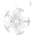
figure 2 is a front view with parts in section and parts removed for clarity of the bearing assembly infigure 1 ; -
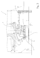
figure 3 is a side view, with parts in section and parts removed for clarity, of a detail of the bearing assembly for a gas turbine infigure 1 ; -
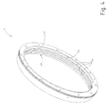
figure 4 is a perspective view, with parts removed for clarity, of a first detail of the bearing assembly infigure 1 ; -
figure 5 is a perspective view, with parts in section and parts removed for clarity, of a second detail of the bearing assembly infigure 1 . - In
figure 1 , a gas turbine is indicated with the reference number 1 (only one portion is shown infigure 1 for the sake of simplicity) comprising arotor section 2, astator section 3, and abearing assembly 4. Therotor section 2 rotates about a longitudinal rotation axis A and is provided with a shaft 5a, which comprises a plurality of rotor discs 5b (known and shown in part in the accompanying figures) and a tie rod 5c, which keeps the rotor discs 5b compacted during rotation about axis A. - The
stator section 3 is fixed and supported by a supporting structure on the ground (not shown in the accompanying figures). - The
bearing assembly 4 is arranged about the shaft 5a substantially at the exhaust of the gas turbine 1 and is coupled to thestator section 3. - The
bearing assembly 4 comprises a supportingbody 6, a bearing 7 (shown only infigures 2 and3 ), which is arranged between the supportingbody 6 and the shaft 5a and is supported by the supportingbody 6, and asealing element 8. - The supporting
body 6 has a substantially cylindrical shape and extends about an axis B, coinciding in use with the rotation axis A of shaft 5a. - With reference to
figure 2 , the supportingbody 6 is coupled with thestator section 3 of the gas turbine 1. In particular, the supportingbody 6 is provided with twocylinders 10, which are coaxial and extend along an axis C orthogonal to axis B. - The
cylinders 10 are arranged diametrically opposite on the middle plane and are adapted to engagerespective seats 11 of thestator section 3 of the gas turbine 1. The cylindrical coupling between theseats 11 and thecylinders 10 allows thebearing assembly 4 to rotate about axis C to follow the movements of the shaft 5a during operation of the gas turbine 1 (as shown by the arrow infigure 2 ). - Preferably, the shape of the
cylinders 10 is complementary to that of therespective seats 11, but undersized. Thecylinders 10 are housed in therespective seats 11 usingshims 12 for adjusting the position of the supportingbody 6 with respect to the shaft 5a so that the rotation axis A of the shaft 5a substantially coincides with axis B of the supportingbody 6. Preferably, theshims 12 are fixed to thestator section 3. - The supporting
body 6 is further provided with acylinder 13, which extends along an axis D orthogonal to axis B and to axis C and adapted to engage arespective ring 14 of aplate 15, which slides in arespective seat 16 of thestator section 3 of the gas turbine 1. - The cylindrical coupling between the
ring 14 of theplate 15 andcylinder 13 allows thebearing assembly 4 to turn about axis C (as shown by the arrow infigure 2 ) to follow the movements of the shaft 5a during operation of the gas turbine 1. - The
seat 16 of thestator section 3 extends parallel to axis B and theplate 15 slides in theseat 16 parallel to axis B to allow the supportingbody 6 to turn about axis C. - Preferably, the shape of the
cylinder 12 is not complementary with theseat 16, but is undersized. Thecylinder 13 is housed in therespective seat 16 usingshims 17 for adjusting the position of the supportingbody 6 with respect to the shaft 5a so that the rotation axis A of the shaft 5a substantially coincides with axis B of the supportingbody 6. Preferably, theshims 17 are fixed to thestator section 3. - With reference to
figures 2 and3 , thebearing 7 is an oscillating slide bearing, which comprises fiveslides 18, arranged equidistant along the inner face of thebearing 7. Eachslide 18 is free to move about a respective supportingpin 19. - In use, the
slides 18 follow the movement of the shaft 5a. - With reference to
figure 3 , thesealing element 8 is supported by the supportingelement 6 at an end of the supportingbody 6 and extends about the shaft 5a. - In particular, the sealing
element 8 is supported by the end of the supportingbody 6 facing the inlet of the gas turbine 1. - The
sealing element 8 separates the lubrication zone of thebearing 7 from the zone of therotor section 2 in which a cooling fluid circulates. The sealing of the sealingelement 8 is fundamental because the leakage of oil from the lubrication zone to therotator section 2 could cause fires and severe damage to the gas turbine 1. - With reference to
figures 1 ,3 and4 , thesealing element 8 comprises agasket 20 and aslide 21. - Both the
gasket 20 and theslide 21, are arranged along the inner surface of the sealingelement 8. In particular, theslide 21 and thegasket 20 are provided in sequence along axis B so that in use theslide 21 is in contact with the lubrication oil of thebearing 7 and theseal 20 is in contact with the cooling fluid which circulates in therotor section 2. - The
gasket 20 is preferably metallic and comprises a plurality ofmetallic foils 22, which are arranged so as to form an array of rings substantially equidistant adapted to prevent the passage of lubrication oil and cooling fluid. - Specifically, the
metallic foils 22 must be made so as to leave a thin gap between themetallic foils 22 and the surface of the shaft 5a (in particular the surface of the respective plate of the shaft 5a), which will be occupied during use by a thin oil film which contributes to the correct sealing action ofgasket 20. - Air, conveyed by means of specific channels, circulates between each
metallic foil 22, and contributes to cool the foils and creates a pressure on the foils which contrasts the pressure generated by the cooling fluid, so as to prevent the fluid from flowing into the lubrication zone of the rotor and, vice versa, the oil from leaking into the cooling fluid passage zone. - A variant not shown of the present invention contemplates that
gasket 20 comprises a sealing ring, e.g. of the type commonly called "Corteco", which comprises a spiral metallic ring, coated with a rubber ring which ensures the seal for direct contact with shaft 5a. - The
slide 21 is substantially a ring fixed to the inner surface of thesealing element 8 and has acontact face 24 made of low friction coefficient material. Preferably, thecontact face 24 is coated with white metal. As for themetallic foils 22, theslide 21 has a diameter such as to leave a thin gap between theslide 21 and the surface of the shaft 5a (in particular the surface of the respective disc 5b of the shaft 5a). Such gap will be occupied during use by a thin film of oil which contributes to the correct sealing action ofslide 21. - With particular reference to
figure 5 , theslide 21 has acoupling edge 25, having a so-called "dovetail" shape, which engages therespective slide 26 made along the inner surface of the sealingelement 8. - Preferably,
slide 21 is lubricated with the pressurized oil of the oscillatingslides 18 ofbearing 7. - Advantageously, the particular configuration of the
sealing element 8 and of the supportingstructure 6 allow thebearing assembly 4 to follow the position oscillations of the shaft 5a, particularly evident during the transient steps in which there is a variation of the rotation speed of shaft 5a. In this manner, stressing of the sealingelement 8 is avoided, avoiding early deterioration of thesealing element 8 itself. - Furthermore, the particular configuration of the
sealing element 8 and of the supportingstructure 6 allows to avoid the long, demanding step of fixing of the supporting structure to therotor section 2. By virtue of such a configuration, indeed, the supportingstructure 6 must not be rigidly fixed to thestator section 3 by means of the traditional holes and alignment pins. This implies a considerable reduction of assembly and/or overall times and costs of thebearing assembly 4. - It is finally apparent that changes and variations can be made to the
bearing assembly 4 and to the gas turbine 1 described herein without departing from the scope of protection of the appended claims.
Claims (13)
- Bearing assembly for a shaft (5a) of a gas turbine (1); the gas turbine (1) comprising a rotor section (2) provided with a shaft (5a) extending along a longitudinal rotation axis (A) and a stator section (3); the bearing assembly(4) comprising:a supporting body (6), which extends about a first axis (B), coinciding, in use, with the rotation axis (A) of the shaft (5a);a bearing (7), which is supported by the supporting body (6) to cooperate, in use, with the shaft (5a); anda sealing element (8), which is supported by the supporting body (6) at an end of the supporting body (6) to cooperate, in use, with the shaft (5a);the bearing assembly (4) being characterized in that the supporting body (6) and the sealing element (8) are configured in such a way to allow the bearing assembly (4) to rotate about at least a second axis (C; D) orthogonal to the first axis (B) to follow displacements of the shaft (5a).
- Bearing assembly according to claim 1, wherein the supporting body (6) and the sealing element (8) are configured in such a way to allow the bearing assembly (4) to rotate about a third axis (D; C) orthogonal to the first axis (B) and the second axis (C; D).
- Bearing assembly according to anyone of the foregoing claims, wherein the supporting body (6) comprises at least one cylinder (10; 13), which extends along the second axis (C; D) and is apt to be rotatably coupled to the stator section (3) of the gas turbine (1) to allow the supporting body (6) to rotate about the second axis (C; D).
- Bearing assembly according to anyone of the foregoing claims, wherein the sealing element (8) comprises a slide (21) having a contact face (24) made of low friction coefficient material.
- Bearing assembly according to claim 4, wherein the contact face (24) of the slide (21) is made of white metal.
- Bearing assembly according to claim 4 or 5, wherein a thin gap is present between the slide (21) and the shaft (5a) for the lubricating oil passage.
- Bearing assembly according to anyone of the claims from 4 to 6, wherein the sealing element (8) comprises a gasket (20).
- Bearing assembly according to anyone of claims from 7 to 9, wherein the slide (21) and the gasket (20) are arranged in sequence along a direction parallel to the first axis (B) in such a way that the slide (21) is in contact with the lubricating oil of the bearing (7) and the gasket (20) is in contact with the cooling fluid which flows in the rotor section (2) of the gas turbine (1).
- Bearing assembly according to claim 7 or 8, wherein the gasket (20) comprises at least a sealing ring.
- Bearing assembly according to any one of claims from 7 to 9, wherein the gasket (20) is a metallic gasket.
- Bearing assembly according to any one of claims from 7 to 10, wherein the gasket (20) comprises a plurality of metallic foils (22), which are arranged as to form an array of substantially equidistant rings.
- Bearing assembly according to claim 11, wherein a thin gap between the metallic foils (22) and the shaft (5a) is present for the lubricating oil passage.
- Gas turbine for an electric power plant comprising a bearing assembly (4) according to anyone of the foregoing claims.
Applications Claiming Priority (1)
| Application Number | Priority Date | Filing Date | Title |
|---|---|---|---|
| ITMI20100293 | 2010-02-24 |
Publications (1)
| Publication Number | Publication Date |
|---|---|
| EP2360351A1 true EP2360351A1 (en) | 2011-08-24 |
Family
ID=42790662
Family Applications (1)
| Application Number | Title | Priority Date | Filing Date |
|---|---|---|---|
| EP11155903A Withdrawn EP2360351A1 (en) | 2010-02-24 | 2011-02-24 | Bearing assembly for a shaft of a gas turbine |
Country Status (1)
| Country | Link |
|---|---|
| EP (1) | EP2360351A1 (en) |
Citations (7)
| Publication number | Priority date | Publication date | Assignee | Title |
|---|---|---|---|---|
| US1374520A (en) * | 1921-04-12 | stanley smith cook | ||
| US1562019A (en) * | 1922-09-05 | 1925-11-17 | Gen Electric | Shaft packing for elastic-fluid turbines and the like |
| US2591399A (en) * | 1947-06-11 | 1952-04-01 | Gen Electric | Power plant frame structure having air-cooling means for turbine rotors and exhaust frame struts |
| GB1309495A (en) * | 1970-05-25 | 1973-03-14 | Owens Illinois Inc | Fluid bearing structure |
| US4302062A (en) * | 1979-09-20 | 1981-11-24 | United Technologies Corporation | Turbine blade support |
| US20060239816A1 (en) * | 2005-04-21 | 2006-10-26 | Pratt & Whitney Canada | Integrated labyrinth and carbon seal |
| WO2009083789A1 (en) * | 2007-12-28 | 2009-07-09 | Ansaldo Energia S.P.A. | Bearing assembly for a gas turbine |
-
2011
- 2011-02-24 EP EP11155903A patent/EP2360351A1/en not_active Withdrawn
Patent Citations (7)
| Publication number | Priority date | Publication date | Assignee | Title |
|---|---|---|---|---|
| US1374520A (en) * | 1921-04-12 | stanley smith cook | ||
| US1562019A (en) * | 1922-09-05 | 1925-11-17 | Gen Electric | Shaft packing for elastic-fluid turbines and the like |
| US2591399A (en) * | 1947-06-11 | 1952-04-01 | Gen Electric | Power plant frame structure having air-cooling means for turbine rotors and exhaust frame struts |
| GB1309495A (en) * | 1970-05-25 | 1973-03-14 | Owens Illinois Inc | Fluid bearing structure |
| US4302062A (en) * | 1979-09-20 | 1981-11-24 | United Technologies Corporation | Turbine blade support |
| US20060239816A1 (en) * | 2005-04-21 | 2006-10-26 | Pratt & Whitney Canada | Integrated labyrinth and carbon seal |
| WO2009083789A1 (en) * | 2007-12-28 | 2009-07-09 | Ansaldo Energia S.P.A. | Bearing assembly for a gas turbine |
Similar Documents
| Publication | Publication Date | Title |
|---|---|---|
| RU2687474C2 (en) | Gas turbine engine compressor comprising blades with variable installation angle | |
| US20120211944A1 (en) | Self-adjusting seal for rotating turbomachinery | |
| JP5398651B2 (en) | Shaft sealing mechanism and rotating machine equipped with the same | |
| US20160222828A1 (en) | Blade outer air seal having angled retention hook | |
| US20140363279A1 (en) | Non-integral segmented angel-wing seal | |
| US20140044526A1 (en) | Stationary blade ring, assembly method and turbomachine | |
| CN105026691A (en) | Gas turbine rotor blade and gas turbine rotor | |
| US20160010751A1 (en) | Shaft seal device and rotary machine | |
| US20160108737A1 (en) | Blade system, and corresponding method of manufacturing a blade system | |
| CA2793080C (en) | Brush ring seal | |
| EP3287619A1 (en) | Variable nozzle mechanism and variable geometry turbocharger | |
| RU2558486C2 (en) | Method and guide to remove internal casing from turbine machine | |
| JP2011252496A (en) | Patch ring segment for turbomachine compressor | |
| US20110285090A1 (en) | Seal assembly including plateau and concave portion in mating surface for seal tooth in turbine | |
| EP3048343A1 (en) | Multi-stage inter shaft ring seal | |
| JP2013181577A (en) | Sealing device and rotary machine including the same | |
| US9103224B2 (en) | Compliant plate seal for use with rotating machines and methods of assembling a rotating machine | |
| US10494944B2 (en) | Seal on the inner ring of a guide vane | |
| CN104246146B (en) | The equipment sealed between the axle coaxial for turbomachinery | |
| RU2425270C1 (en) | Radial end contact seal of support of turbomachine | |
| EP2360351A1 (en) | Bearing assembly for a shaft of a gas turbine | |
| JP5802741B2 (en) | Rotating anode X-ray tube and inspection device | |
| CN204716310U (en) | A kind of gas turbine air seal structure | |
| JP4387697B2 (en) | Steam turbine seal device and steam turbine provided with the same | |
| CN101413425A (en) | Intermediate body assembly for turbocharger |
Legal Events
| Date | Code | Title | Description |
|---|---|---|---|
| PUAI | Public reference made under article 153(3) epc to a published international application that has entered the european phase |
Free format text: ORIGINAL CODE: 0009012 |
|
| AK | Designated contracting states |
Kind code of ref document: A1 Designated state(s): AL AT BE BG CH CY CZ DE DK EE ES FI FR GB GR HR HU IE IS IT LI LT LU LV MC MK MT NL NO PL PT RO RS SE SI SK SM TR |
|
| AX | Request for extension of the european patent |
Extension state: BA ME |
|
| 17P | Request for examination filed |
Effective date: 20120224 |
|
| RIC1 | Information provided on ipc code assigned before grant |
Ipc: F01D 25/16 20060101ALI20120420BHEP Ipc: F01D 11/02 20060101ALI20120420BHEP Ipc: F01D 11/00 20060101AFI20120420BHEP |
|
| GRAP | Despatch of communication of intention to grant a patent |
Free format text: ORIGINAL CODE: EPIDOSNIGR1 |
|
| STAA | Information on the status of an ep patent application or granted ep patent |
Free format text: STATUS: THE APPLICATION IS DEEMED TO BE WITHDRAWN |
|
| 18D | Application deemed to be withdrawn |
Effective date: 20121012 |