EP2360306A2 - Drum type washing machine - Google Patents
Drum type washing machine Download PDFInfo
- Publication number
- EP2360306A2 EP2360306A2 EP11003983A EP11003983A EP2360306A2 EP 2360306 A2 EP2360306 A2 EP 2360306A2 EP 11003983 A EP11003983 A EP 11003983A EP 11003983 A EP11003983 A EP 11003983A EP 2360306 A2 EP2360306 A2 EP 2360306A2
- Authority
- EP
- European Patent Office
- Prior art keywords
- balancer
- spin tub
- washing machine
- wall
- annular
- Prior art date
- Legal status (The legal status is an assumption and is not a legal conclusion. Google has not performed a legal analysis and makes no representation as to the accuracy of the status listed.)
- Granted
Links
Images


Classifications
-
- D—TEXTILES; PAPER
- D06—TREATMENT OF TEXTILES OR THE LIKE; LAUNDERING; FLEXIBLE MATERIALS NOT OTHERWISE PROVIDED FOR
- D06F—LAUNDERING, DRYING, IRONING, PRESSING OR FOLDING TEXTILE ARTICLES
- D06F37/00—Details specific to washing machines covered by groups D06F21/00 - D06F25/00
- D06F37/20—Mountings, e.g. resilient mountings, for the rotary receptacle, motor, tub or casing; Preventing or damping vibrations
- D06F37/22—Mountings, e.g. resilient mountings, for the rotary receptacle, motor, tub or casing; Preventing or damping vibrations in machines with a receptacle rotating or oscillating about a horizontal axis
- D06F37/225—Damping vibrations by displacing, supplying or ejecting a material, e.g. liquid, into or from counterbalancing pockets
Definitions
- the present invention relates generally to a drum type washing machine, and more particularly to a drum type washing machine including a balancer capable of rapidly reducing vibration of a spin tub.
- a drum type washing machine rotates a drum so that the laundry loaded in the drum moves upward and then drops from the top to the bottom of the drum, thereby washing the laundry.
- the drum type washing machine includes a housing forming an external appearance of the drum type washing machine, a water reservoir accommodated in the housing to receive water therein, a spin tub rotatably installed in the water reservoir, and a driving motor generating rotational force by receiving electric power so as to rotate the spin tub connected to a rotating shaft of the driving motor.
- the drum type washing machine is provided with a shaft flange formed at the center thereof with a rotating shaft and fixed to a rear surface of the spin tub so as to uniformly transfer the rotational force of the driving motor to the rotating shaft, and a balancer fixed to the rear surface of the spin tub so as to rapidly reduce vibration generated when the spin tub is rotated.
- the shaft flange includes a hub section for installing the rotating shaft, and a plurality of arm sections extending radially outward from the hub section so as to be fixed to the rotating shaft.
- the balancer includes a balancer housing formed with an annular race that allows a mass accommodated in the balancer housing to move in the circumferential direction, and a ball movably installed in the annular race so as to serve as the mass.
- the balancer housing includes first and second balancer housings coupled to each other through fusion welding while forming the race therebetween.
- the ball accommodated in the balancer housing is subject to centrifugal force during the rotation of spin tub, so the ball repeatedly collides with the first and second balancer housings. If the ball applies such impact to the first and second balancer housings for a long period of time, the connection part between the first and second balancer housings is weakened, so that the first balancer housing is separated from the second housing. In this case, the ball accommodated in the race of the balancer housing may move out of the race.
- an object of the present invention is to provide a drum type washing machine capable of preventing a ball accommodated in a balancer from moving out of the balancer, even if the balancer is broken due to long-period use of the balancer.
- a spin tub may include a spin tub body having a cylindrical shape and a rear surface of which is opened, and a rear cover covering the rear surface of the spin tub body, a part of a rear end portion of the spin tub body protrudes toward a rear side of the rear cover, and an outer end portion of the shaft flange is fixed to the part of the rear end portion of the spin tub body that protrudes toward the rear side of the rear cover.
- a support section can be provided at an outer peripheral end portion of the rear cover, in which the support section extends rearward in parallel to the spin tub body such that an outer peripheral surface of the rear balancer is supported by the support section and an outer peripheral end portion of the shaft flange is fixed to the support section.
- An annular groove may be formed at the outer peripheral end portion of the rear cover so as to receive the rear balancer, and the rear balancer is rested in the annular groove by means of the shaft flange.
- the rear balancer can include first and second balancer housings having annular shapes and being coupled to each other such that a race, in which a plurality of balls are movably installed, is formed between the first and second balancer housings.
- the drum type washing machine includes a housing 10 having a box shape forming an external appearance of the drum type washing machine, a water reservoir 30 accommodated in the housing 10 to receive water therein, a spin tub 40 rotatably installed in the water reservoir 30 and having a cylindrical structure formed with a plurality of pores 40b allowing water and air to pass through the spin tub 40, and a driving motor 50 transferring power to the spin tub 40 so as to rotate the spin tub 40 such that the laundry contained in the spin tub 40 can be washed and dehydrated.
- Openings 30a and 40a are formed at front center portions of the water reservoir 30 and the spin tub 40 so as to allow the user to put the laundry into the spin tub 40 or to take out the laundry from the spin tub 40.
- a door 20 is hinged to the front surface of the housing 10 so as to open/close the openings 30a and 40a of the water reservoir 30 and the spin tub 40.
- Lifters 40c are provided on the inner peripheral wall of the spin tub 40 at a predetermined interval. As the spin tub 40 rotates in the forward and reverse directions, the laundry placed in the spin tub 40 is moved upward and then dropped downward in the spin tub 40 by means of the lifters 40c, so that the laundry is washed.
- the spin tub 40 includes a spin tub body 41 having a cylindrical shape and being installed lengthwise along the spin tub 40, in which front and rear surfaces of the spin tub body 41 are opened, and covers 42 and 43 covering the front and rear surfaces of the spin tub body 41.
- the covers 42 and 43 include a front cover 42 (see FIG. 2 ) covering the front surface of the spin tub 40 and being formed at the center thereof with the opening 40a so as to allow the user to put the laundry into the spin tub 40, and a rear cover 43 covering the rear surface of the spin tub 40 and being provided at the center thereof with a rotating shaft 53 that transfers driving force of the driving motor 50.
- the driving motor 50 includes a stator unit 51 fixed to the rear surface of the water reservoir 30, a rotor unit 52 rotatably installed around the stator unit 51, and a rotating shaft 53 having a first end installed at the rotor unit 52 and a second end installed at the rear cover 43 forming the rear surface of the spin tub 40 by passing through the water reservoir 30.
- a shaft flange 60 provided at the center thereof with the rotating shaft 53 is fixed to the rear surface of the spin tub 40 so as to uniformly transfer the rotational force of the driving motor 50 to the spin tub 40, so that the spin tub 40 is rotated by receiving the rotational force of the driving motor 50 through the shaft flange 60.
- the shaft flange 60 uniformly transfers the rotational force of the driving motor to various portions of the spin tub 40, thereby preventing excessive force from being transferred to a specific part of the spin tub 40.
- the shaft flange 60 includes a hub section 61 for fixedly installing the rotating shaft 53, and a plurality of arm sections 62 extending radially outward from the hub section 61 so as to be fixed to the outer peripheral end portion of the spin tub 40 while being spaced apart from each other in the circumferential direction at a predetermined interval.
- the shaft flange 60 has three arm sections 62. The rotational force of the driving motor 50 is uniformly transferred to three spots of the outer peripheral end portion of the spin tub 40 through the three arm sections 62.
- the front and rear covers 42 and 43 that form the front and rear surfaces of the spin tub 40 are provided with balancers 70F and 70R, respectively.
- the balancers 70F and 70R rapidly reduce vibration of the spin tub 40, which is generated during the rotation of the spin tub due to unbalance of the laundry placed in the spin tub, thereby stabilizing the rotation of the spin tub 40 in the early stage.
- the balancer 70F installed at the front side of the spin tub 40 is referred to as a front balancer 70F and the balancer 70R installed at the rear side of the spin tub 40 is referred to as a rear balancer 70R.
- a mass is installed in the balancers 70F and 70R in such a manner that the mass can move in the circumferential direction of the balancers 70F and 70R. If the unbalance occurs due to the weight of laundry placed in the spin tub 40, the mass accommodated in the balancers 70F and 70R moves in the circumferential direction so as to compensate for the unbalance. Thus, the vibration of the spin tub 40 caused by the unbalance mass can be rapidly reduced.
- the rear balancer 70R installed at the rear cover 43 includes first and second balancer housings 71 and 72 having an annular shape and being coupled with each other such that a race 73, which is a moving route of the mass, can be formed therebetween, and a plurality of balls 74 is movably installed in the race 73 so as to serve as the mass.
- the first balancer housing 71 may be coupled with the second balancer housing 72 through fusion welding, etc.
- the drum type washing machine of the present invention at least a part of the rear balancer 70R is supported on the rear surface of the rear cover 43 by means of the shaft flange 60, so that the front and rear surfaces of the rear balancer 70R are supported on the rear surface of the rear cover 43 and the front surface of the arm section 62 of the shaft flange 60, respectively.
- the first and second balancer housings 71 and 72 can be secured to each other. Since the first balancer housing 71 can be secured to the second balancer housing 72, the balls 74 installed in the rear balancer 70R can be prevented from moving out of the rear balancer 70R.
- the shaft flange 60 includes three arm sections 62, so at least three spots of the rear balancer 70R are supported by means of the three arm sections 62.
- a groove 43a is formed in the rear cover 43.
- the groove 43a has an annular shape corresponding to the shape of the rear balancer 70R such that the rear balancer 70R can be rested in the groove 43a.
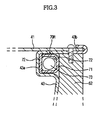
- a part of the rear end portion of the spin tub body 41 protrudes toward the rear side of the rear cover 43, so that the end portion of the arm section 62 of the shaft flange 60 is fixed to the protruding part of the rear end portion of the spin tub body 41, as shown in FIG. 3 . Accordingly, the rear balancer 70R can be stably installed in the groove 43a by means of the arm section 62 of the shaft flange 60.
- a supporter 43b is provided at the outer peripheral end portion of the rear cover 43.
- the supporter 43b extends in the rear direction in parallel to the spin tub body 41 and the outer peripheral surface of the rear balancer 70R is supported on the inner surface of the supporter 43b and the end portion of the arm section 62 is fixed to the inner surface of the supporter 43b.
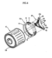
- FIG. 4 is an exploded perspective view showing the arrangement of a rear balancer 70R and a shaft flange 80 provided in a drum type washing machine according to a second embodiment of the present invention.
- the rear balancer 70R applied to the drum type washing machine according to a second embodiment of the present invention includes first and second balancer housings 71 and 72 having an annular shape and being coupled with each other such that a race 73, which is a moving route of the mass, can be formed therebetween, and a plurality of balls 74 movably installed in the race 73 so as to serve as the mass.
- the shaft flange 80 includes a hub section 81 for installing the rotating shaft 53, and a plurality of arm sections 82 extending radially outward from the hub section 81 while being spaced apart from each other in the circumferential direction at a predetermined interval.
- first and second balancer housings 71 and 72 constituting the rear balancer 70R is installed on the shaft flange 80 such that the first and second balancer housings 71 and 72 are supported against each other.
- the first and second balancer housings 71 and 72 can be secured to each other, thereby preventing the balls 74 installed in the race 73 from moving out of the race 73.
- balancer supports 83 which are opened toward the rear surface of the spin tub 40 so as to support the rear balancer 70R installed thereon, are provided at outer end portions of the shaft flange 80.
- the balancer supports 83 extend from end portions of the arm sections 82 of the shaft flange 80 and are formed with mounting grooves 83a which are opened toward the rear surface of the spin tub 40 so as to mount the rear balancer 70R thereon.
- end portions of the balancer supports 83 are fixed to the spin tub 40 by means of a coupling member, such as a bolt, so that the shaft flange 80 can be fixed to the spin tub 40 through the balancer supports 83.
- the shaft flange 80 includes three arm sections 62 and three balancer supports 83 extend from end portions of three arm sections 62.
- parts of three spots of the rear balancer 70R are rested in the mounting grooves 83a formed in three arm sections 82, respectively. Therefore, since the parts of three spots of the rear balancer 70R are rested in the mounting grooves 83a, the front, rear, outer peripheral and inner peripheral surfaces of the rear balancer 70R are supported by the rear surface of the spin tub 40 and the inner surfaces of the mounting grooves of the shaft flange 80.
- the first and second balancer housings 71 and 72 can be secured to each other, thereby preventing the balls 74 from moving out of the race 73.
- the rotational center of the rear balancer 70R precisely matches with the rotational center of the rotating shaft 53. Accordingly, there is no need to perform precision work for matching the rotational center of the rear balancer 70R with the rotational center of the rotating shaft 53, so that assembly work for the drum type washing machine can be simplified.
- a cross section of the annular shaped body of the balancer (70F, 70R) comprises an inner wall and an outer wall facing the inner wall, which outer wall is disposed farther from the centre of the balancer (70F, 70R) than the inner wall, a first connecting wall and a second connecting wall formed between the inner wall and the outer wall to define said internal quadrilateral space, wherein the outer wall contacting the balls (74) contained therein during rotation of the spin tub (40) is formed as an undivided and unitary piece.
- a depth of the annular groove (43a) for accommodating the annular shaped body of the balancer (70F, 70R) is selected such that at least a centre of each of the balls (74) contained in the annular shaped body is disposed completely within the annular groove.
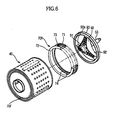
- FIG. 6 is an exploded perspective view showing the arrangement of a balancer and a shaft flange provided in a drum type washing machine according to a third embodiment of the present invention.
- the shaft flange 90 provided in the drum type washing machine includes a hub section 91 for installing the rotating shaft 53, a plurality of arm sections 92 extending radially outward from the hub section 91 while being spaced apart from each other in the circumferential direction, and a balancer support 93 extending in the circumferential direction while connecting outer end portions of the arm sections 92 to each other such that the rear balancer 70R can be installed on the balancer support 93.
- the balancer support 93 is formed with an annular groove 93a which is opened toward the rear surface of the spin tub 40.
- the annular groove 93a is formed in the balancer support 93 for mounting the rear balancer 70R, the front, rear, outer peripheral and inner peripheral surfaces of the rear balancer 70R are wholly supported by the rear surface of the spin tub 40 and the inner surface of the annular groove 93a. Accordingly, even if the connection part between the first and second balancer housings 71 and 72 is broken, the first and second balancer housings 71 and 72 can be secured to each other, thereby preventing the balls 74 from moving out of the race 73. In addition, impact caused by collision of balls 74 is partially transferred to the balancer support 93, so that impact applied to the first and second balancer housings 71 and 72 can be reduced. Thus, the connection part between the first and second balancer housings 71 and 72 can be protected from breakage.
- the balancer since the balancer is supported on the rear surface of the spin tub by means of the shaft flange, the balls accommodated in the balancer can be prevented from moving out of the balancer, even if the balancer is broken due to long-period use.
- the balancer is mounted on the shaft flange provided at the center thereof with the rotating shaft, so that the rotational center of the balancer can be easily matched with the rotational center of the rotating shaft.
Landscapes
- Engineering & Computer Science (AREA)
- Textile Engineering (AREA)
- Main Body Construction Of Washing Machines And Laundry Dryers (AREA)
Abstract
Description
- The present invention relates generally to a drum type washing machine, and more particularly to a drum type washing machine including a balancer capable of rapidly reducing vibration of a spin tub.
- In general, a drum type washing machine rotates a drum so that the laundry loaded in the drum moves upward and then drops from the top to the bottom of the drum, thereby washing the laundry. The drum type washing machine includes a housing forming an external appearance of the drum type washing machine, a water reservoir accommodated in the housing to receive water therein, a spin tub rotatably installed in the water reservoir, and a driving motor generating rotational force by receiving electric power so as to rotate the spin tub connected to a rotating shaft of the driving motor.
- In addition, the drum type washing machine is provided with a shaft flange formed at the center thereof with a rotating shaft and fixed to a rear surface of the spin tub so as to uniformly transfer the rotational force of the driving motor to the rotating shaft, and a balancer fixed to the rear surface of the spin tub so as to rapidly reduce vibration generated when the spin tub is rotated.
- The shaft flange includes a hub section for installing the rotating shaft, and a plurality of arm sections extending radially outward from the hub section so as to be fixed to the rotating shaft. The balancer includes a balancer housing formed with an annular race that allows a mass accommodated in the balancer housing to move in the circumferential direction, and a ball movably installed in the annular race so as to serve as the mass. The balancer housing includes first and second balancer housings coupled to each other through fusion welding while forming the race therebetween.
- However, according to the balancer having the above structure, the ball accommodated in the balancer housing is subject to centrifugal force during the rotation of spin tub, so the ball repeatedly collides with the first and second balancer housings. If the ball applies such impact to the first and second balancer housings for a long period of time, the connection part between the first and second balancer housings is weakened, so that the first balancer housing is separated from the second housing. In this case, the ball accommodated in the race of the balancer housing may move out of the race.
- Additional aspects and/or advantages of the invention will be set forth in part in the description which follows and, in part, will be apparent from the description, or may be learned by practice of the invention.
- Accordingly, the present invention has been made to solve above-mentioned problems occurring in the prior art, and an object of the present invention is to provide a drum type washing machine capable of preventing a ball accommodated in a balancer from moving out of the balancer, even if the balancer is broken due to long-period use of the balancer.
- This object is solved by the features of claim 1.
- A spin tub may include a spin tub body having a cylindrical shape and a rear surface of which is opened, and a rear cover covering the rear surface of the spin tub body, a part of a rear end portion of the spin tub body protrudes toward a rear side of the rear cover, and an outer end portion of the shaft flange is fixed to the part of the rear end portion of the spin tub body that protrudes toward the rear side of the rear cover.
- A support section can be provided at an outer peripheral end portion of the rear cover, in which the support section extends rearward in parallel to the spin tub body such that an outer peripheral surface of the rear balancer is supported by the support section and an outer peripheral end portion of the shaft flange is fixed to the support section.
- An annular groove may be formed at the outer peripheral end portion of the rear cover so as to receive the rear balancer, and the rear balancer is rested in the annular groove by means of the shaft flange.
- The rear balancer can include first and second balancer housings having annular shapes and being coupled to each other such that a race, in which a plurality of balls are movably installed, is formed between the first and second balancer housings.
- Advantageous embodiments are disclosed by the sub claims.
- The above and other objects, features and advantages of the present invention will be more apparent from the following detailed description taken in conjunction with the accompanying drawings, in which:
-
FIG. 1 is a sectional view showing the structure of a drum type washing machine according to a first embodiment of the present invention; -
FIG. 2 is an exploded perspective view showing the arrangement of a balancer and a shaft flange provided in a drum type washing machine according to a first embodiment of the present invention; -
FIG. 3 is a sectional view showing the arrangement of a balancer and a shaft flange provided in a drum type washing machine according to a first embodiment of the present invention; -
FIG. 4 is an exploded perspective view showing the arrangement of a balancer and a shaft flange provided in a drum type washing machine according to a second embodiment of the present invention; -
FIG. 5 is a sectional view showing the arrangement of a balancer and a shaft flange provided in a drum type washing machine according to a second embodiment of the present invention; and -
FIG. 6 is an exploded perspective view showing the arrangement of a balancer and a shaft flange provided in a drum type washing machine according to a third embodiment of the present invention. - Reference will now be made in detail to the embodiments of the present invention, examples of which are illustrated in the accompanying drawings, wherein like reference numerals refer to the like elements throughout. The embodiments are described below to explain the present invention by referring to the figures.
- Hereinafter, a drum type washing machine according to a first embodiment of the present invention will be described with reference to accompanying drawings.
- As shown in
FIG. 1 , the drum type washing machine according to the present invention includes ahousing 10 having a box shape forming an external appearance of the drum type washing machine, a water reservoir 30 accommodated in thehousing 10 to receive water therein, aspin tub 40 rotatably installed in the water reservoir 30 and having a cylindrical structure formed with a plurality ofpores 40b allowing water and air to pass through thespin tub 40, and a drivingmotor 50 transferring power to thespin tub 40 so as to rotate thespin tub 40 such that the laundry contained in thespin tub 40 can be washed and dehydrated. -
Openings spin tub 40 so as to allow the user to put the laundry into thespin tub 40 or to take out the laundry from thespin tub 40. Adoor 20 is hinged to the front surface of thehousing 10 so as to open/close theopenings spin tub 40.Lifters 40c are provided on the inner peripheral wall of thespin tub 40 at a predetermined interval. As thespin tub 40 rotates in the forward and reverse directions, the laundry placed in thespin tub 40 is moved upward and then dropped downward in thespin tub 40 by means of thelifters 40c, so that the laundry is washed. - The
spin tub 40 includes aspin tub body 41 having a cylindrical shape and being installed lengthwise along thespin tub 40, in which front and rear surfaces of thespin tub body 41 are opened, and covers 42 and 43 covering the front and rear surfaces of thespin tub body 41. Thecovers FIG. 2 ) covering the front surface of thespin tub 40 and being formed at the center thereof with the opening 40a so as to allow the user to put the laundry into thespin tub 40, and arear cover 43 covering the rear surface of thespin tub 40 and being provided at the center thereof with a rotatingshaft 53 that transfers driving force of thedriving motor 50. - The
driving motor 50 includes astator unit 51 fixed to the rear surface of the water reservoir 30, arotor unit 52 rotatably installed around thestator unit 51, and a rotatingshaft 53 having a first end installed at therotor unit 52 and a second end installed at therear cover 43 forming the rear surface of thespin tub 40 by passing through the water reservoir 30. - In addition, a
shaft flange 60 provided at the center thereof with the rotatingshaft 53 is fixed to the rear surface of thespin tub 40 so as to uniformly transfer the rotational force of the drivingmotor 50 to thespin tub 40, so that thespin tub 40 is rotated by receiving the rotational force of the drivingmotor 50 through theshaft flange 60. - The shaft flange 60 uniformly transfers the rotational force of the driving motor to various portions of the
spin tub 40, thereby preventing excessive force from being transferred to a specific part of thespin tub 40. As shown inFIG. 2 , theshaft flange 60 includes ahub section 61 for fixedly installing therotating shaft 53, and a plurality ofarm sections 62 extending radially outward from thehub section 61 so as to be fixed to the outer peripheral end portion of thespin tub 40 while being spaced apart from each other in the circumferential direction at a predetermined interval. According to the present embodiment, theshaft flange 60 has threearm sections 62. The rotational force of the drivingmotor 50 is uniformly transferred to three spots of the outer peripheral end portion of thespin tub 40 through the threearm sections 62. - In addition, the front and
rear covers spin tub 40 are provided withbalancers balancers spin tub 40, which is generated during the rotation of the spin tub due to unbalance of the laundry placed in the spin tub, thereby stabilizing the rotation of thespin tub 40 in the early stage. In the present embodiment, thebalancer 70F installed at the front side of thespin tub 40 is referred to as afront balancer 70F and thebalancer 70R installed at the rear side of thespin tub 40 is referred to as arear balancer 70R. - A mass is installed in the
balancers balancers spin tub 40, the mass accommodated in thebalancers spin tub 40 caused by the unbalance mass can be rapidly reduced. - The
rear balancer 70R installed at therear cover 43 includes first andsecond balancer housings race 73, which is a moving route of the mass, can be formed therebetween, and a plurality ofballs 74 is movably installed in therace 73 so as to serve as the mass. Thefirst balancer housing 71 may be coupled with thesecond balancer housing 72 through fusion welding, etc. - According to the drum type washing machine of the present invention, at least a part of the
rear balancer 70R is supported on the rear surface of therear cover 43 by means of theshaft flange 60, so that the front and rear surfaces of therear balancer 70R are supported on the rear surface of therear cover 43 and the front surface of thearm section 62 of theshaft flange 60, respectively. Thus, even if the connection part between the first andsecond balancer housings second balancer housings first balancer housing 71 can be secured to thesecond balancer housing 72, theballs 74 installed in therear balancer 70R can be prevented from moving out of therear balancer 70R. According to the present embodiment, theshaft flange 60 includes threearm sections 62, so at least three spots of therear balancer 70R are supported by means of the threearm sections 62. - In addition, in order to allow the
rear balancer 70R to be supported by the rear surface of therear cover 43 and the front surface of thearm section 62 of theshaft flange 60, agroove 43a is formed in therear cover 43. Thegroove 43a has an annular shape corresponding to the shape of therear balancer 70R such that therear balancer 70R can be rested in thegroove 43a. In addition, a part of the rear end portion of thespin tub body 41 protrudes toward the rear side of therear cover 43, so that the end portion of thearm section 62 of theshaft flange 60 is fixed to the protruding part of the rear end portion of thespin tub body 41, as shown inFIG. 3 . Accordingly, therear balancer 70R can be stably installed in thegroove 43a by means of thearm section 62 of theshaft flange 60. - According to the present embodiment, a
supporter 43b is provided at the outer peripheral end portion of therear cover 43. Thesupporter 43b extends in the rear direction in parallel to thespin tub body 41 and the outer peripheral surface of therear balancer 70R is supported on the inner surface of thesupporter 43b and the end portion of thearm section 62 is fixed to the inner surface of thesupporter 43b. -
FIG. 4 is an exploded perspective view showing the arrangement of arear balancer 70R and ashaft flange 80 provided in a drum type washing machine according to a second embodiment of the present invention. - The
rear balancer 70R applied to the drum type washing machine according to a second embodiment of the present invention includes first andsecond balancer housings race 73, which is a moving route of the mass, can be formed therebetween, and a plurality ofballs 74 movably installed in therace 73 so as to serve as the mass. Theshaft flange 80 includes ahub section 81 for installing the rotatingshaft 53, and a plurality ofarm sections 82 extending radially outward from thehub section 81 while being spaced apart from each other in the circumferential direction at a predetermined interval. - In addition, at least a part of the first and
second balancer housings rear balancer 70R is installed on theshaft flange 80 such that the first andsecond balancer housings second balancer housings second balancer housings balls 74 installed in therace 73 from moving out of therace 73. - To this end, balancer supports 83, which are opened toward the rear surface of the
spin tub 40 so as to support therear balancer 70R installed thereon, are provided at outer end portions of theshaft flange 80. The balancer supports 83 extend from end portions of thearm sections 82 of theshaft flange 80 and are formed with mountinggrooves 83a which are opened toward the rear surface of thespin tub 40 so as to mount therear balancer 70R thereon. In addition, end portions of the balancer supports 83 are fixed to thespin tub 40 by means of a coupling member, such as a bolt, so that theshaft flange 80 can be fixed to thespin tub 40 through the balancer supports 83. - According to the present embodiment, the
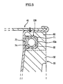
shaft flange 80 includes threearm sections 62 and three balancer supports 83 extend from end portions of threearm sections 62. Thus, as shown inFIG. 5 , parts of three spots of therear balancer 70R are rested in the mountinggrooves 83a formed in threearm sections 82, respectively. Therefore, since the parts of three spots of therear balancer 70R are rested in the mountinggrooves 83a, the front, rear, outer peripheral and inner peripheral surfaces of therear balancer 70R are supported by the rear surface of thespin tub 40 and the inner surfaces of the mounting grooves of theshaft flange 80. Accordingly, even if the connection part between the first andsecond balancer housings second balancer housings balls 74 from moving out of therace 73. - In this manner, if the
rear balancer 70R is installed in on the shaft flange provided with the rotatingshaft 53 through the mountinggrooves 83a, the rotational center of therear balancer 70R precisely matches with the rotational center of therotating shaft 53. Accordingly, there is no need to perform precision work for matching the rotational center of therear balancer 70R with the rotational center of therotating shaft 53, so that assembly work for the drum type washing machine can be simplified. - In
FIG. 3 and5 a cross section of the annular shaped body of the balancer (70F, 70R) comprises an inner wall and an outer wall facing the inner wall, which outer wall is disposed farther from the centre of the balancer (70F, 70R) than the inner wall, a first connecting wall and a second connecting wall formed between the inner wall and the outer wall to define said internal quadrilateral space, wherein the outer wall contacting the balls (74) contained therein during rotation of the spin tub (40) is formed as an undivided and unitary piece. A depth of the annular groove (43a) for accommodating the annular shaped body of the balancer (70F, 70R) is selected such that at least a centre of each of the balls (74) contained in the annular shaped body is disposed completely within the annular groove. -
FIG. 6 is an exploded perspective view showing the arrangement of a balancer and a shaft flange provided in a drum type washing machine according to a third embodiment of the present invention. - As shown in
FIG. 6 , the shaft flange 90 provided in the drum type washing machine according to the third embodiment of the present invention includes ahub section 91 for installing the rotatingshaft 53, a plurality ofarm sections 92 extending radially outward from thehub section 91 while being spaced apart from each other in the circumferential direction, and abalancer support 93 extending in the circumferential direction while connecting outer end portions of thearm sections 92 to each other such that therear balancer 70R can be installed on thebalancer support 93. Thebalancer support 93 is formed with anannular groove 93a which is opened toward the rear surface of thespin tub 40. - Since the
annular groove 93a is formed in thebalancer support 93 for mounting therear balancer 70R, the front, rear, outer peripheral and inner peripheral surfaces of therear balancer 70R are wholly supported by the rear surface of thespin tub 40 and the inner surface of theannular groove 93a. Accordingly, even if the connection part between the first andsecond balancer housings second balancer housings balls 74 from moving out of therace 73. In addition, impact caused by collision ofballs 74 is partially transferred to thebalancer support 93, so that impact applied to the first andsecond balancer housings second balancer housings - As described above, according to the drum type washing machine of the present invention, since the balancer is supported on the rear surface of the spin tub by means of the shaft flange, the balls accommodated in the balancer can be prevented from moving out of the balancer, even if the balancer is broken due to long-period use.
- In addition, according to the drum type washing machine of the present invention, the balancer is mounted on the shaft flange provided at the center thereof with the rotating shaft, so that the rotational center of the balancer can be easily matched with the rotational center of the rotating shaft.
- Although a few embodiments of the present invention have been shown and described, it would be appreciated by those skilled in the art that changes may be made in these embodiments without departing from the principles of the invention, the scope of which is defined in the claims and their equivalents.
- The following embodiments are also possible.
- 1. A drum type washing machine comprising:
- a spin tub which is rotated by receiving rotational force from a driving motor through a rotating shaft;
- a rear balancer having an annular shape and being coupled to the spin tub; and
- a shaft flange provided at a center portion thereof with the rotating shaft and coupled to the spin tub so as to uniformly transfer the rotational force to the spin tub,
- wherein the rear balancer is supported on a rear surface of a rear cover by means of the shaft flange.
- 2. The drum type washing machine as according to 1, wherein the spin tub includes a spin tub body having a cylindrical shape and a rear surface of which is opened, and the rear cover covering the rear surface of the spin tub body, a part of a rear end portion of the spin tub body protrudes toward a rear side of the rear cover, and an outer end portion of the shaft flange is fixed to the part of the rear end portion of the spin tub body that protrudes toward the rear side of the rear cover.
- 3. The drum type washing machine according to 2, wherein a support section is provided at an outer peripheral end portion of the rear cover, in which the support section extends rearward in parallel to the spin tub body such that an outer peripheral surface of the rear balancer is supported by the support section and an outer peripheral end portion of the shaft flange is fixed to the support section.
- 4. The drum type washing machine according to 2, wherein an annular groove is formed at the outer peripheral end portion of the rear cover so as to receive the rear balancer, and the rear balancer is rested in the annular groove by means of the shaft flange.
- 5. The drum type washing machine according to 1, wherein the rear balancer includes first and second balancer housings having annular shapes and being coupled to each other such that a race, in which a plurality of balls are movably installed, is formed between the first and second balancer housings.
- Further embodiments may be
- 6. A drum type washing machine comprising:
- a spin tub which is rotated by receiving rotational force from a driving motor through a rotating shaft;
- a rear balancer having an annular shape and reducing vibration of the spin tub; and
- a shaft flange provided at a center portion thereof with the rotating shaft and coupled to the spin tub so as to uniformly transfer the rotational force to the spin tub,
- wherein the rear balancer is installed on the shaft flange.
- 7. The drum type washing machine according to 6, wherein the shaft flange includes a balancer support on which the rear balancer is installed.
- 8. The drum type washing machine according to 7, wherein the balancer support is formed with a groove in which the rear balancer is rested, and the groove is opened toward a rear surface of the spin tub.
- 9. The drum type washing machine according to 8, wherein the shaft flange includes a hub section for installing the rotating shaft, and a plurality of arm sections extending radially outward from the hub section so as to be fixed to the spin tub, in which the balancer support extends from end portions of the arm sections.
- 10. The drum type washing machine according to 8, wherein the balancer support has an annular shape and is connected to the arm sections.
- 11. The drum type washing machine according to 8, wherein the rear balancer includes first and second balancer housings having annular shapes and being coupled to each other such that a race, in which a plurality of balls are movably installed, is formed between the first and second balancer housings.
Claims (6)
- A drum type washing machine comprising:a housing (10);a water reservoir (30) installed in the housing (10) to receive water therein;a spin tub (40) rotatable by receiving a rotational force from a driving motor (50) through a rotating shaft (53), the spin tub (40) including an annular groove (43a) provided along an outer circumferential edge of the spin tub (40), anda balancer (70F, 70R) having an annular shaped body coupled to the annular group (43a) and including a plurality of balls (74) disposed and movable within an internal space of the annular shaped body of the balancer (70F, 70R), the annular shaped body of the balancer having a cross section providing an internal quadrilateral space, wherein corners of this internal quadrilateral space are rounded,wherein said cross section of the annular shaped body of the balancer (70F, 70R) comprises an inner wall and an outer wall facing the inner wall, which outer wall is disposed farther from the centre of the balancer (70F, 70R) than the inner wall, a first connecting wall and a second connecting wall formed between the inner wall and the outer wall to define said internal quadrilateral space,wherein the outer wall contacting the balls (74) contained therein during rotation of the spin tub (40) is formed as an undivided and unitary piece andwherein a depth of the annular groove (43a) for accommodating the annular shaped body of the balancer (70F, 70R) is selected such that at least a centre of each of the balls (74) contained in the annular shaped body is disposed completely within the annular groove.
- The washing machine according to claim 1, wherein the shape of the annular groove (43a) corresponds to the shape of the balancer (70F, 70R) such that the balancer is coupled to the spin tub (40).
- The washing machine according to claim 1, wherein the front end and the rear end of the spin tub (40) includes a front cover (42) and a rear cover (43), respectively, wherein a balancer (70F, 70R) is coupled to each of the front cover (42) and the rear cover (43), with annular grooves (43a) provided at the front and the rear cover (41, 43) of the spin tub (40) to couple the balancers (70F, 70R) to opposite ends of the spin tub (40).
- The washing machine according to claim 1, wherein the rounded corners of the annular shaped body of the balancer (70F, 70R) provide increased strength to the balancer.
- The washing machine according to claim 1, wherein the balancer (70F, 70R) is self-contained and separate from the spin tub (40) and is removably fitted within the annular groove (43a).
- The washing machine according to claim 1, wherein the balls (74) moving within the balancer (70F, 70R) are in a two-point contact state during the rotation of the spin tub (40).
Applications Claiming Priority (3)
| Application Number | Priority Date | Filing Date | Title |
|---|---|---|---|
| KR1020060049494A KR101003353B1 (en) | 2006-06-01 | 2006-06-01 | Drum washing machine |
| KR1020060049497A KR101273587B1 (en) | 2006-06-01 | 2006-06-01 | Drum type washing machine |
| EP07109185A EP1862578B1 (en) | 2006-06-01 | 2007-05-30 | Drum Type Washing Machine |
Related Parent Applications (2)
| Application Number | Title | Priority Date | Filing Date |
|---|---|---|---|
| EP07109185.4 Division | 2007-05-30 | ||
| EP07109185A Division EP1862578B1 (en) | 2006-06-01 | 2007-05-30 | Drum Type Washing Machine |
Publications (3)
| Publication Number | Publication Date |
|---|---|
| EP2360306A2 true EP2360306A2 (en) | 2011-08-24 |
| EP2360306A3 EP2360306A3 (en) | 2012-06-20 |
| EP2360306B1 EP2360306B1 (en) | 2016-04-06 |
Family
ID=38537532
Family Applications (3)
| Application Number | Title | Priority Date | Filing Date |
|---|---|---|---|
| EP11003983.1A Revoked EP2360306B1 (en) | 2006-06-01 | 2007-05-30 | Drum type washing machine |
| EP07109185A Active EP1862578B1 (en) | 2006-06-01 | 2007-05-30 | Drum Type Washing Machine |
| EP11003982.3A Active EP2365118B1 (en) | 2006-06-01 | 2007-05-30 | Drum type washing machine |
Family Applications After (2)
| Application Number | Title | Priority Date | Filing Date |
|---|---|---|---|
| EP07109185A Active EP1862578B1 (en) | 2006-06-01 | 2007-05-30 | Drum Type Washing Machine |
| EP11003982.3A Active EP2365118B1 (en) | 2006-06-01 | 2007-05-30 | Drum type washing machine |
Country Status (2)
| Country | Link |
|---|---|
| EP (3) | EP2360306B1 (en) |
| ES (1) | ES2389862T3 (en) |
Families Citing this family (6)
| Publication number | Priority date | Publication date | Assignee | Title |
|---|---|---|---|---|
| EP2436825B1 (en) | 2006-06-01 | 2021-01-13 | Samsung Electronics Co., Ltd. | Washing machine having balancer |
| EP2360306B1 (en) | 2006-06-01 | 2016-04-06 | Samsung Electronics Co., Ltd. | Drum type washing machine |
| KR102025781B1 (en) | 2013-01-04 | 2019-11-04 | 삼성전자주식회사 | Balancer and washing machine having the same |
| CN108070984B (en) * | 2016-11-09 | 2021-07-23 | 重庆海尔洗衣机有限公司 | An inner barrel bottom gimbal assembly and washing machine |
| CN107164925B (en) * | 2017-06-26 | 2020-05-19 | 无锡小天鹅电器有限公司 | Drum type laundry treating apparatus |
| CN111764108B (en) * | 2019-03-13 | 2022-10-04 | 青岛海尔洗衣机有限公司 | Balance ring liquid leakage detection method and device and washing machine |
Family Cites Families (16)
| Publication number | Priority date | Publication date | Assignee | Title |
|---|---|---|---|---|
| DE2633604A1 (en) * | 1976-07-27 | 1978-02-02 | Licentia Gmbh | Tub for front loading washing machine - with rear wall and supporting ring clamped to tub |
| NL8200479A (en) | 1982-02-09 | 1983-09-01 | Philips Nv | SHAVER. |
| KR970011122A (en) | 1995-08-28 | 1997-03-27 | 김광호 | Balance of washing machine |
| KR100207022B1 (en) | 1995-09-06 | 1999-07-01 | 김광호 | Balancer of a washer |
| EP0781882B2 (en) * | 1995-12-28 | 2005-08-10 | Samsung Electronics Co., Ltd. | Drum appliances with balancing devices |
| KR100189108B1 (en) * | 1996-05-11 | 1999-06-01 | 윤종용 | Balancing apparatus of a drum washer |
| JP2957144B2 (en) | 1996-05-23 | 1999-10-04 | 三星電子株式会社 | Ball balancer for washing machine |
| KR0136040Y1 (en) | 1996-05-30 | 1999-05-15 | 김광호 | Balancing Device for Drum Washing Machine |
| KR100763367B1 (en) * | 2000-11-15 | 2007-10-04 | 엘지전자 주식회사 | Drum Washing Machine |
| US20040253312A1 (en) | 2001-09-28 | 2004-12-16 | Sowden Harry S. | Immediate release dosage form comprising shell having openings therein |
| JP4152348B2 (en) | 2004-06-03 | 2008-09-17 | 株式会社ソニー・コンピュータエンタテインメント | Electronic device cooling apparatus, electronic device system, and electronic device cooling method |
| JP4745720B2 (en) | 2004-06-03 | 2011-08-10 | キヤノン株式会社 | Film forming method, and spacer and thin flat panel display manufacturing method using the same |
| KR100640866B1 (en) | 2004-09-08 | 2006-11-02 | 엘지전자 주식회사 | Balancer of washing machine |
| KR20060049494A (en) | 2004-10-05 | 2006-05-19 | 주식회사 엘지화학 | Nanocomposite composition with excellent barrier properties |
| EP2360306B1 (en) | 2006-06-01 | 2016-04-06 | Samsung Electronics Co., Ltd. | Drum type washing machine |
| EP2436825B1 (en) | 2006-06-01 | 2021-01-13 | Samsung Electronics Co., Ltd. | Washing machine having balancer |
-
2007
- 2007-05-30 EP EP11003983.1A patent/EP2360306B1/en not_active Revoked
- 2007-05-30 EP EP07109185A patent/EP1862578B1/en active Active
- 2007-05-30 EP EP11003982.3A patent/EP2365118B1/en active Active
- 2007-05-30 ES ES07109185T patent/ES2389862T3/en active Active
Non-Patent Citations (1)
| Title |
|---|
| None |
Also Published As
| Publication number | Publication date |
|---|---|
| EP2365118A3 (en) | 2012-08-29 |
| EP2360306A3 (en) | 2012-06-20 |
| EP2365118B1 (en) | 2017-12-27 |
| EP1862578A3 (en) | 2009-03-11 |
| EP1862578A2 (en) | 2007-12-05 |
| EP2365118A2 (en) | 2011-09-14 |
| EP2360306B1 (en) | 2016-04-06 |
| EP1862578B1 (en) | 2012-06-27 |
| ES2389862T3 (en) | 2012-11-02 |
Similar Documents
| Publication | Publication Date | Title |
|---|---|---|
| US7814769B2 (en) | Drum type washing machine | |
| KR101295361B1 (en) | Drum type washing machine | |
| US8783072B2 (en) | Drum-type washing machine and bearing housing structure thereof | |
| EP2360306B1 (en) | Drum type washing machine | |
| EP1978145B1 (en) | Drum washing machine with supporting hinges | |
| EP2292828B1 (en) | Drum-type washing machine | |
| US20050179347A1 (en) | Drum type washing machine | |
| JP2000325693A (en) | Drum type washing machine | |
| US20040148981A1 (en) | Tub assembly in drum-type washing machine | |
| KR101003353B1 (en) | Drum washing machine | |
| KR101417782B1 (en) | Drum type washing machine | |
| KR101220218B1 (en) | Drum type washing machine | |
| JP6845415B2 (en) | Washing machine | |
| KR100716252B1 (en) | Rotating tub body and drum washing machine with same | |
| KR101219370B1 (en) | Drum type washing machine | |
| KR101220215B1 (en) | Drum type washing machine | |
| CN112204189A (en) | Washing machine | |
| KR20160073139A (en) | Top load type washing machine |
Legal Events
| Date | Code | Title | Description |
|---|---|---|---|
| PUAI | Public reference made under article 153(3) epc to a published international application that has entered the european phase |
Free format text: ORIGINAL CODE: 0009012 |
|
| AC | Divisional application: reference to earlier application |
Ref document number: 1862578 Country of ref document: EP Kind code of ref document: P |
|
| AK | Designated contracting states |
Kind code of ref document: A2 Designated state(s): DE ES FR GB IT |
|
| PUAL | Search report despatched |
Free format text: ORIGINAL CODE: 0009013 |
|
| AK | Designated contracting states |
Kind code of ref document: A3 Designated state(s): DE ES FR GB IT |
|
| RIC1 | Information provided on ipc code assigned before grant |
Ipc: D06F 37/22 20060101AFI20120511BHEP |
|
| RAP1 | Party data changed (applicant data changed or rights of an application transferred) |
Owner name: SAMSUNG ELECTRONICS CO., LTD. |
|
| 17P | Request for examination filed |
Effective date: 20121218 |
|
| 17Q | First examination report despatched |
Effective date: 20130423 |
|
| GRAP | Despatch of communication of intention to grant a patent |
Free format text: ORIGINAL CODE: EPIDOSNIGR1 |
|
| INTG | Intention to grant announced |
Effective date: 20151203 |
|
| GRAS | Grant fee paid |
Free format text: ORIGINAL CODE: EPIDOSNIGR3 |
|
| GRAA | (expected) grant |
Free format text: ORIGINAL CODE: 0009210 |
|
| AC | Divisional application: reference to earlier application |
Ref document number: 1862578 Country of ref document: EP Kind code of ref document: P |
|
| AK | Designated contracting states |
Kind code of ref document: B1 Designated state(s): DE ES FR GB IT |
|
| REG | Reference to a national code |
Ref country code: GB Ref legal event code: FG4D |
|
| REG | Reference to a national code |
Ref country code: DE Ref legal event code: R096 Ref document number: 602007045702 Country of ref document: DE |
|
| PG25 | Lapsed in a contracting state [announced via postgrant information from national office to epo] |
Ref country code: ES Free format text: LAPSE BECAUSE OF FAILURE TO SUBMIT A TRANSLATION OF THE DESCRIPTION OR TO PAY THE FEE WITHIN THE PRESCRIBED TIME-LIMIT Effective date: 20160406 |
|
| REG | Reference to a national code |
Ref country code: DE Ref legal event code: R026 Ref document number: 602007045702 Country of ref document: DE |
|
| PG25 | Lapsed in a contracting state [announced via postgrant information from national office to epo] |
Ref country code: IT Free format text: LAPSE BECAUSE OF FAILURE TO SUBMIT A TRANSLATION OF THE DESCRIPTION OR TO PAY THE FEE WITHIN THE PRESCRIBED TIME-LIMIT Effective date: 20160406 |
|
| PLBI | Opposition filed |
Free format text: ORIGINAL CODE: 0009260 |
|
| PLAB | Opposition data, opponent's data or that of the opponent's representative modified |
Free format text: ORIGINAL CODE: 0009299OPPO |
|
| 26 | Opposition filed |
Opponent name: BOCK WOLFGANG Effective date: 20161222 |
|
| PLAX | Notice of opposition and request to file observation + time limit sent |
Free format text: ORIGINAL CODE: EPIDOSNOBS2 |
|
| R26 | Opposition filed (corrected) |
Opponent name: BOCK, WOLFGANG Effective date: 20161222 |
|
| REG | Reference to a national code |
Ref country code: FR Ref legal event code: ST Effective date: 20170131 |
|
| PG25 | Lapsed in a contracting state [announced via postgrant information from national office to epo] |
Ref country code: FR Free format text: LAPSE BECAUSE OF NON-PAYMENT OF DUE FEES Effective date: 20160606 |
|
| PLBB | Reply of patent proprietor to notice(s) of opposition received |
Free format text: ORIGINAL CODE: EPIDOSNOBS3 |
|
| RDAF | Communication despatched that patent is revoked |
Free format text: ORIGINAL CODE: EPIDOSNREV1 |
|
| STAA | Information on the status of an ep patent application or granted ep patent |
Free format text: STATUS: THE PATENT HAS BEEN GRANTED |
|
| APBM | Appeal reference recorded |
Free format text: ORIGINAL CODE: EPIDOSNREFNO |
|
| APBP | Date of receipt of notice of appeal recorded |
Free format text: ORIGINAL CODE: EPIDOSNNOA2O |
|
| APAH | Appeal reference modified |
Free format text: ORIGINAL CODE: EPIDOSCREFNO |
|
| APBQ | Date of receipt of statement of grounds of appeal recorded |
Free format text: ORIGINAL CODE: EPIDOSNNOA3O |
|
| PGFP | Annual fee paid to national office [announced via postgrant information from national office to epo] |
Ref country code: DE Payment date: 20210420 Year of fee payment: 15 |
|
| PGFP | Annual fee paid to national office [announced via postgrant information from national office to epo] |
Ref country code: GB Payment date: 20210422 Year of fee payment: 15 |
|
| REG | Reference to a national code |
Ref country code: DE Ref legal event code: R103 Ref document number: 602007045702 Country of ref document: DE Ref country code: DE Ref legal event code: R064 Ref document number: 602007045702 Country of ref document: DE |
|
| APBU | Appeal procedure closed |
Free format text: ORIGINAL CODE: EPIDOSNNOA9O |
|
| RDAG | Patent revoked |
Free format text: ORIGINAL CODE: 0009271 |
|
| STAA | Information on the status of an ep patent application or granted ep patent |
Free format text: STATUS: PATENT REVOKED |
|
| 27W | Patent revoked |
Effective date: 20220118 |
|
| GBPR | Gb: patent revoked under art. 102 of the ep convention designating the uk as contracting state |
Effective date: 20220118 |