EP2360114A1 - Method of producing a polymer stamp for the reproduction of devices comprising microstructures and nanostructures, a corresponding polymer stamp, a corresponding device and a fuel delivery system or water management system for fuel cells - Google Patents
Method of producing a polymer stamp for the reproduction of devices comprising microstructures and nanostructures, a corresponding polymer stamp, a corresponding device and a fuel delivery system or water management system for fuel cells Download PDFInfo
- Publication number
- EP2360114A1 EP2360114A1 EP10153537A EP10153537A EP2360114A1 EP 2360114 A1 EP2360114 A1 EP 2360114A1 EP 10153537 A EP10153537 A EP 10153537A EP 10153537 A EP10153537 A EP 10153537A EP 2360114 A1 EP2360114 A1 EP 2360114A1
- Authority
- EP
- European Patent Office
- Prior art keywords
- nanostructures
- microstructures
- substrate
- polymer
- polymer stamp
- Prior art date
- Legal status (The legal status is an assumption and is not a legal conclusion. Google has not performed a legal analysis and makes no representation as to the accuracy of the status listed.)
- Granted
Links
Images


Classifications
-
- B—PERFORMING OPERATIONS; TRANSPORTING
- B81—MICROSTRUCTURAL TECHNOLOGY
- B81C—PROCESSES OR APPARATUS SPECIALLY ADAPTED FOR THE MANUFACTURE OR TREATMENT OF MICROSTRUCTURAL DEVICES OR SYSTEMS
- B81C99/00—Subject matter not provided for in other groups of this subclass
- B81C99/0075—Manufacture of substrate-free structures
- B81C99/009—Manufacturing the stamps or the moulds
-
- B—PERFORMING OPERATIONS; TRANSPORTING
- B81—MICROSTRUCTURAL TECHNOLOGY
- B81C—PROCESSES OR APPARATUS SPECIALLY ADAPTED FOR THE MANUFACTURE OR TREATMENT OF MICROSTRUCTURAL DEVICES OR SYSTEMS
- B81C1/00—Manufacture or treatment of devices or systems in or on a substrate
- B81C1/00015—Manufacture or treatment of devices or systems in or on a substrate for manufacturing microsystems
- B81C1/00206—Processes for functionalising a surface, e.g. provide the surface with specific mechanical, chemical or biological properties
-
- H—ELECTRICITY
- H01—ELECTRIC ELEMENTS
- H01M—PROCESSES OR MEANS, e.g. BATTERIES, FOR THE DIRECT CONVERSION OF CHEMICAL ENERGY INTO ELECTRICAL ENERGY
- H01M8/00—Fuel cells; Manufacture thereof
- H01M8/02—Details
- H01M8/0202—Collectors; Separators, e.g. bipolar separators; Interconnectors
- H01M8/0258—Collectors; Separators, e.g. bipolar separators; Interconnectors characterised by the configuration of channels, e.g. by the flow field of the reactant or coolant
-
- H—ELECTRICITY
- H01—ELECTRIC ELEMENTS
- H01M—PROCESSES OR MEANS, e.g. BATTERIES, FOR THE DIRECT CONVERSION OF CHEMICAL ENERGY INTO ELECTRICAL ENERGY
- H01M8/00—Fuel cells; Manufacture thereof
- H01M8/04—Auxiliary arrangements, e.g. for control of pressure or for circulation of fluids
- H01M8/04082—Arrangements for control of reactant parameters, e.g. pressure or concentration
- H01M8/04089—Arrangements for control of reactant parameters, e.g. pressure or concentration of gaseous reactants
- H01M8/04119—Arrangements for control of reactant parameters, e.g. pressure or concentration of gaseous reactants with simultaneous supply or evacuation of electrolyte; Humidifying or dehumidifying
- H01M8/04156—Arrangements for control of reactant parameters, e.g. pressure or concentration of gaseous reactants with simultaneous supply or evacuation of electrolyte; Humidifying or dehumidifying with product water removal
- H01M8/04164—Arrangements for control of reactant parameters, e.g. pressure or concentration of gaseous reactants with simultaneous supply or evacuation of electrolyte; Humidifying or dehumidifying with product water removal by condensers, gas-liquid separators or filters
-
- B—PERFORMING OPERATIONS; TRANSPORTING
- B81—MICROSTRUCTURAL TECHNOLOGY
- B81B—MICROSTRUCTURAL DEVICES OR SYSTEMS, e.g. MICROMECHANICAL DEVICES
- B81B2201/00—Specific applications of microelectromechanical systems
- B81B2201/05—Microfluidics
- B81B2201/051—Micromixers, microreactors
-
- B—PERFORMING OPERATIONS; TRANSPORTING
- B81—MICROSTRUCTURAL TECHNOLOGY
- B81C—PROCESSES OR APPARATUS SPECIALLY ADAPTED FOR THE MANUFACTURE OR TREATMENT OF MICROSTRUCTURAL DEVICES OR SYSTEMS
- B81C2201/00—Manufacture or treatment of microstructural devices or systems
- B81C2201/01—Manufacture or treatment of microstructural devices or systems in or on a substrate
- B81C2201/0101—Shaping material; Structuring the bulk substrate or layers on the substrate; Film patterning
- B81C2201/0147—Film patterning
- B81C2201/015—Imprinting
- B81C2201/0153—Imprinting techniques not provided for in B81C2201/0152
-
- B—PERFORMING OPERATIONS; TRANSPORTING
- B81—MICROSTRUCTURAL TECHNOLOGY
- B81C—PROCESSES OR APPARATUS SPECIALLY ADAPTED FOR THE MANUFACTURE OR TREATMENT OF MICROSTRUCTURAL DEVICES OR SYSTEMS
- B81C2201/00—Manufacture or treatment of microstructural devices or systems
- B81C2201/03—Processes for manufacturing substrate-free structures
- B81C2201/034—Moulding
-
- H—ELECTRICITY
- H01—ELECTRIC ELEMENTS
- H01M—PROCESSES OR MEANS, e.g. BATTERIES, FOR THE DIRECT CONVERSION OF CHEMICAL ENERGY INTO ELECTRICAL ENERGY
- H01M8/00—Fuel cells; Manufacture thereof
- H01M8/10—Fuel cells with solid electrolytes
- H01M2008/1095—Fuel cells with polymeric electrolytes
-
- Y—GENERAL TAGGING OF NEW TECHNOLOGICAL DEVELOPMENTS; GENERAL TAGGING OF CROSS-SECTIONAL TECHNOLOGIES SPANNING OVER SEVERAL SECTIONS OF THE IPC; TECHNICAL SUBJECTS COVERED BY FORMER USPC CROSS-REFERENCE ART COLLECTIONS [XRACs] AND DIGESTS
- Y02—TECHNOLOGIES OR APPLICATIONS FOR MITIGATION OR ADAPTATION AGAINST CLIMATE CHANGE
- Y02E—REDUCTION OF GREENHOUSE GAS [GHG] EMISSIONS, RELATED TO ENERGY GENERATION, TRANSMISSION OR DISTRIBUTION
- Y02E60/00—Enabling technologies; Technologies with a potential or indirect contribution to GHG emissions mitigation
- Y02E60/30—Hydrogen technology
- Y02E60/50—Fuel cells
Definitions
- the present invention relates to a method of producing a polymer stamp for the reproduction of devices comprising microstructures and nanostructures, a polymer stamp and a device comprising microstructures and nanostructures. It particularly relates to micro devices which could be used in micro fuel cell system as fuel delivery systems or water management systems with microstructures and nanostructures.
- the device preferably consists of a polymer.
- the main replication techniques of polymer based devices are injection moulding and hot embossing and micro-machining.
- nanoimprint technology NIL
- UV-nanoimprint-technology can be used.
- soft lithography techniques like microcontact printing (CP) and micro-moulding have been established which offer new possibilities of nanostructuring.
- One of the problems is the fuel delivery.
- the fuel must be transported to the anode, where the reaction takes place.
- CO 2 is produced, which must be transported out of the system to avoid a hindrance for the fuel. Therefore the separation of liquid and gas and the transportation of gas out of the device is a decisive factor for the improvement of fuel cells.
- Both problems can be solved by exploiting wetting properties of surfaces.
- fuel used in such applications can easily be transported to the anode through hydrophilic channels.
- the CO 2 on the other hand can be separated and transported out of the device through hydrophobic channels.
- a device that is capable to solve those problems may contain both hydrophobic and hydrophilic channels.
- the fuel must be supplied to the system. Therefore a through-hole for fuel supply must be integrated in such a device as well, which is difficult to form with hot embossing.
- a diffusion medium for use in a PEM fuel cell contains hydrophobic and hydrophilic areas for improved water management.
- a hydrophobic polymer such as a fluororesin is used to define hydrophobic areas
- an electroconductive polymer such as polyaniline or polypyrrole is used for defining hydrophilic areas.
- two different polymers need to be used for the formation of such channels making the fabrication process very complex.
- DE 102 32 129 A1 discloses a fluid distribution device for an electrochemical electrode, wherein coatings are used to form hydrophobic and hydrophilic areas.
- a coating exhibits a limited lifetime.
- each final product needs to be coated separately with the coating in order to produce hydrophobic and hydrophilic areas.
- the present invention provides a method of producing a polymer stamp for the reproduction of devices comprising microstructures and nanostructures, the method comprising the steps of providing a first substrate, patterning nanostructures into the first substrate material, patterning microstructures onto the first substrate, casting a polymer elastomer onto the first substrate with nanostructures and microstructures to form a polymer stamp and releasing the polymer stamp.
- the process has the advantage that the nanostructures are formed directly into the substrate surface.
- the substrate preferably consists of a single material or material compound but may also comprise different layers of materials.
- the nanostructures and microstructures can be directly transferred to the polymer stamp at low costs.
- the direct integration of nanostructured areas in microdevices improves the functionality of the device, e.g. the formation of antireflection structures for optical applications or the change of wetting properties in microchannels.
- a method of producing a polymer stamp for the reproduction of devices comprising microstructures and nanostructures comprising the steps of providing a thermoplastic foil, providing a first substrate, patterning nanostructures into the thermoplastic foil, patterning microstructures onto the first substrate, covering the first substrate surface having the microstructures with the thermoplastic foil, casting a polymer elastomer onto the first substrate with nanostructures and microstructures to form a polymer stamp, and releasing the polymer stamp.
- the foil of the second embodiment has the advantage that nanostructures can be transferred directly onto the microstructures in all dimensions, whereas in the first embodiment the nanostructures are formed between the microstructures.
- the step of patterning nanostructures into the thermoplastic foil preferably comprises the step of hot-embossing nanostructures into the foil.
- the step of covering the first substrate surface preferably comprises the step of deforming the thermoplastic foil onto the microstructures by thermoforming.
- the invention is directed to a method of reproducing devices comprising microstructures and nanostructures comprising the steps of casting a final product material onto the polymer stamp with microstructures and nanostructures produced according to the invention as described above, wherein the microstructures and nanostructures are transferred during the casting step to the final product, and releasing the final product of the polymer stamp.
- the final product or device is preferably also a polymer device.
- the device being formed is preferably a microdevice.
- a simple and low cost casting step on the polymer stamp can be employed to repeatedly form the final product under the transfer of micro- and nanostructures to the final product.
- the stamp exhibits the inverse structure of the final product.
- a bottom of the channel in the final product will be a top in the stamp.
- we will usually refer to the orientation of the structures of the final product instead of the stamp, unless specifically stated otherwise.
- the step of patterning nanostructures into the first substrate material or into the thermoplastic foil preferably comprises the step of forming hydrophilic sections along a first direction and hydrophobic sections along a second, different direction by arranging the nanostructures to extend along a first direction.
- the second direction is preferably perpendicular to the first direction.
- hydrophilic and hydrophobic areas can be created in the respective surfaces without any additional layers or chemical coatings.
- the surfaces are functionalized by topographic nanostructures .
- the step of pattering microstructures preferably comprises at least one of the steps of forming first microstructures to extend along the first direction to form hydrophilic channels together with the nanostructures extending in said first direction, and forming second microstructures to extend along a second, different direction to form hydrophobic channels together with the nanostructures extending in the first direction.
- hydrophilic channels can be created.
- the channels have the microstructures as the side walls and the nanostructures are formed at least on the bottom of the microstructures.
- the microstructures provide guides for a fluid along the direction in which the nanostructures are formed. However, along a different, second direction, the nanostructures become more and more hydrophobic. The maximum of hydrophobicity is established in a direction perpendicular to the first direction. If microstructures are now formed along this second, preferably perpendicular direction as well, hydrophobic and hydrophilic structures are formed simply by the mutual alignment or misalignment of nano- and microstructures.
- the step of patterning microstructures preferably further comprises at least one of the steps of forming the first microstructures with a width of 50-500pm, preferably 100-200 ⁇ m and a height of 10-1000 ⁇ m, preferably 50-200 ⁇ m, and forming the second microstructures with a width of 1-100 ⁇ m, preferably 5-50 ⁇ m and a height of 10-1000 ⁇ m, preferably 50-200 ⁇ m.
- the size ranges of the microstructures improve their desired functionality as hydrophilic or hydrophobic channels.
- the step of patterning nanostructures comprises at least one of the steps of forming the nanostructures with a pitch of 50nm-3500nm, preferably 500-1000nm and/or providing the nanostructures with a cross-section being triangular, rectangular or pillar-shaped and forming the nanostructure as lines and spaces.
- the aspect ratio of the height to the width of the nanostructures is preferably 1:2.
- the maximum height of the nanostructures is preferably lower than 1 ⁇ m.
- the size ranges of the nanostructures or -patterns maximize their distinguishing character of being hydrophilic in a first direction and hydrophobic in a second, different direction.
- the lines and spaces provide a very simple way to direct fluids into their direction of extension.
- the nanostructures are hydrophilic.
- their character becomes hydrophobic, with a maximum of hydrophobicity along the perpendicular direction.
- the step of patterning nanostructures into the first substrate material preferably comprises the steps of covering the first substrate with a first resist, transferring nanostructures into the first resist by means of nanolithography processes, covering the first substrate with the nanostructured first resist with a metal layer, removal of the first resist with the metal on top, wherein the first substrate areas without the resist remain covered by the metal, forming nanostructures into the parts of the first substrate not covered with the metal by etching the surface of the first substrate using the remaining metal as a mask, and removing the metal from the first substrate.
- the nanolithography processes are preferably UV lithography, nanoimprint lithography, hot-embossing, electron-beam lithography, interference lithography or X-ray interference lithography.
- the microstructure patterning step may comprise the step of covering the first substrate with a second resist being a photo resist and performing a lithography process.
- lithography processes are well known, easy to handle and can be used to form very precise structures.
- UV lithography, electron-beam lithography, interference lithography or X-ray lithography may be used.
- the second resist preferably comprises polymethylmethacrylate, phenolic resins or epoxy-resins.
- the microstructure patterning step preferably comprises the step of forming a through hole through the second resist and the first substrate.
- the through-hole may be formed by potassium hydroxide etching, deep reactive ion etching, microdrilling or-milling, or laser ablation.
- the casting step of the stamp and the final product allows to easily incorporate a through-hole into the final product required for instance in fuel cell applications.
- the through-hole and the micro- and nanostructures are formed in the final product in a single casting step.
- the method may further comprise the steps of cutting the first substrate to obtain a pre-master comprising the nanostructured first substrate and the microstructured resin, and fixing the pre-master on a second substrate.
- the polymer elastomer preferably comprises polydimethylsiloxane (PDMS).
- PDMS has advantageously a relative low absorption rate for UV applications.
- the final product material used for casting preferably comprises polymer materials. It may comprise a photo resin, an epoxy-based resin, a thermal-curing material, an UV curing material, or a thermoplastic material.
- Polymer materials in general have the advantage of a good biocompatibility and chemical stability and resistance against fuels like ethanol and methanol as well as good optical properties.
- the present invention is directed to a polymer stamp comprising first micro-channels extending along a first direction, second micro-channels extending along a second direction, and nanostructures formed at least on one surface of the first and/or second micro-channels of the polymer stamp, the nanostructures being provided to extend at least along said first direction.
- the nanostructures are patterned directly into at least one surface of the microchannels.
- the nanostructures are formed of the same material as the microstructures themselves. They may be formed of the same material as the bulk material of the polymer stamp. In any case, no additional chemical layers are necessary.
- the topography of the polymer stamp material itself is physically changed at its surface.
- the stamp consists of a single material or material compound and the nanostructures are formed of this stamp material. The surface is functionalized by the topographic structure.
- the invention provides a device comprising first microchannels extending along a first direction, second micro-channels extending along a second direction, nanostructures formed at least on the bottom of the first and/or second microchannels and provided to extend at least along said first direction.
- the nanostructures are patterned into the surface of the microchannels.
- the nanostructures are formed of the same material as the microchannels themselves or are formed of the same material as the bulk material of the microdevice.
- the device consists of a single material or material compound and the nanostructures are formed of this device material. No additional layers, no coating or chemical treatment with molecules is required.
- the topography of the polymer stamp material is physically changed at its surface. The surface is functionalized by the topographic structures.
- the device is preferably a single, fully integrated component. An assembly is not required.
- microchannels consist of the microstructures as the side walls, wherein at least on the bottom of the microchannel the nanostructures are provided. They may also be provided on the side walls and top wall of the microchannels.
- the nanostructures provide a contact angles of 0°-90°, preferably 30°-75° along the first direction, and 90°-160°, preferably 110-150° along the second direction. Preferably, they have a pitch of 70nm-3500nm, more preferably 500-1000nm.
- the aspect ratio of the height to the width of the nanostructures is preferably 1:2.
- the maximum height of the nanostructures is preferably lower than 1 ⁇ m.
- the nanostructures are preferably provided with a cross-section being triangular, rectangular or pillar-shaped. They may be provided as lines and spaces. The lines extend along the first direction.
- the first micro-channels have a width of 50-500 ⁇ m, preferably 100-200 ⁇ m and a height of 10-1000 ⁇ m, preferably 50-200 ⁇ m.
- the second micro-channels have a width of 1-100 ⁇ m, preferably 5-50 ⁇ m and a height of 10-1000 ⁇ m, preferably 50-200 ⁇ m.
- the device may further comprise a through-hole extending from one surface of the device to be in communication with the microchannels.
- the device is preferably a micro-device.
- the device forms a part of a micro fuel cell system wherein the device is preferably a fuel delivery system, the first microchannels are fuel delivery microchannels, and the second microchannels are gas exhaust microchannels and the through-hole is a fuel supply.
- the device is a water management system of a fuel cell system, the first microchannels are water outlet microchannels, the second microchannels are used as reactant supplies and the through-hole is a water exit.
- the reactant is preferably oxygen.
- the device according to the invention can be used in fuel cell applications, wherein the separation of liquids and gases and the transportation of gases out of the device is achieved by the relative arrangement of first microstructures along the direction of extension of nanostructures on the one hand and second microstructures along a second, different, preferably perpendicular direction thereto on the other hand.
- the hydrophobic surfaces of the microchannels can be used for gas separation.
- the microstructures, preferably the second microstructures may form openings in side walls of the device for the separation/exhaust of gaseous by-products created during operation of the fuel cell.
- microchannels allow advantageously a passive flow of fluids.
- the transport is capillary and diffusion driven and therefore the device of the present invention can be used as a passive device for a fuel cell system.
- the transport is alsoorientation independent.
- the device can be easily integrated or bonded to a micro fuel cell system.
- Figs. 1 to 10 show the method of producing a polymer stamp of Fig. 9 and a final product of Fig. 10 according to a first embodiment.
- the stamp is formed to produce a component for a fuel cell system.
- other applications like optics are also possible.
- the production of the stamp and the final product itself is not limited to fuel cell applications but rather to applications which require the formation of nanostructures along with microstructures.
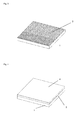
- Fig. 1 shows the first step of the method of producing a polymer stamp with nanostructures and microstructures according to the first embodiment, the provision of a first substrate 1.
- the first substrate 1 may a silicon wafer, may comprise glass or a thermoplastic polymer, but is not limited thereto.
- the first substrate 1 may be formed of a single material or material compound or may comprise different layers.
- nanostructures 3 are transferred into the first substrate surface. This may be done by means of nanolithography processes, preferably by UV lithography, nanoimprint lithography, hot embossing, e-beam lithography, interference lithography, X-ray interference lithography.
- the step of patterning nanostructures 3 into the first substrate 1 preferably comprises the steps of covering the first substrate with a first resist as shown in Fig. 2 . Then, nanostructures are transferred or formed into the first resist by means of one of the above mentioned nanolithography processes.
- the nanostructures may be lines and spaces as shown in Fig. 3 . However, the lines may also consist of separate elements like columns, pyramids and so on.
- the cross section of the lines or the nanostructures 3 may be rectangular, triangular etc.. It is only necessary to provide a smaller spacing of the nanostructures 3 in the desired first direction than in the second, different direction.
- the first substrate 1 with the nanostructured first resist 2 is subsequently covered with a metal layer (not shown).
- the first resist 2 is then removed with the metal on top, wherein the areas of the first substrate 1 without the first resist 2 remain covered by the metal.
- These covered parts act like a mask for an etching process of nanostructures 3 into the parts of the first substrate 1 not covered with the metal.
- the etching may form valleys into the surface of the first substrate 1, and the covered parts may remain as plateaus.
- the metal covered parts form spaces between the channels connecting the channel side walls.
- the metal is removed from the first substrate 1 as can be seen in Fig. 3 and a nanostructured first substrate surface remains.
- the next step of the fabrication process is shown in Fig. 4 , the formation of a second resist 4 on the nanostructures surface of the first substrate 1.
- the second resist 4 is than patterned to exhibit first microstructures 5 and second microstructures 6 as well as other structures like further side walls 28 ( Fig. 5 ).
- the structure as displayed in Fig. 5 surrounded by the second resist structures 28 is equivalent to the structure of the final product.
- the first microstructures 5 are formed along the direction of extension of the nanostructures 3 thereby forming hydrophilic structures for a fluid transport.
- the second microstructures 6 are formed in a second, perpendicular to the direction of extension of the nanostructures 3 (being the direction of the valleys in Fig. 5 ) thereby forming hydrophobic structures, which can be used for a liquid/gas separation.
- the gas is transported along the second microstructures 6 to the periphery of the photo resists structures 4.
- the first and second microstructures 5, 6 are connected via an area of nanostructures 3, only.
- a through-hole 7 is formed through the second resist 4 and the first substrate 1. This is preferably done by potassium hydroxide etching, deep reactive ion etching, microdrilling or micromilling, or laser ablation.
- the device is then cut along the periphery of the second resist 4 patterns, preferably by a laser.
- the cut-out device of Fig. 6 could be called a pre-master 9.
- the pre-master 9 already comprises a through-hole 7, first and second microstructures 5, 6, nanostructures 3 and further side walls 28.
- the pre-master 9 comprises in the exemplary embodiment the substrate layer 1 with nanostructures 3 in its surface and further structures like first and second microstructures 5, 6 and side walls 28 on its surface.
- the pre-master 9 is then - preferably but not limiting - fixed on a second substrate 8 ( Fig. 7 ).
- the first casting process takes place, i.e. a polymer material 10 is cast on top of the pre-master 9 attached to the second substrate 8 as shown in Fig. 8 .
- a frame may be used around the pre-master 9.
- the stamp 11 is released from the pre-master 9 ( Fig. 9 ).
- the polymer stamp 11 now has the inverse structure of the pre-master 9, i.e. were the pre-master 9 had hills, the stamp 11 has valleys and vice versa.
- a through hole fabrication structure 14, a column can be seen.
- a final product material is filled into the stamp 11 and the final product 12 of Fig. 10 is formed in a casting process.
- the final product 12 has the same structural elements as the pre-master, i.e. a through-hole 7, first and second microstructures 5, 6, nanostructures 3 and further side walls 28.
- the final product 11 consists of a single material. No substrate is present anymore.
- the micro- and nanostructures are transferred to the final product.
- the final product has openings 13 at its side walls being in communication with second microchannels formed by the second microstructures 6 as side walls and the nanostructures 3 forming the bottom of the microchannels.
- the first microchannels 5 are perpendicular to the second microchannels 6.
- the first and second microchannels 5, 6 form a T-like structure.
- the areas of the first and second microchannels 5, 6 do preferably not overlap with each other, having an area, e.g. rectangular, with nanostructures 3 only in between used for the separation of liquids and gases. As the fuel liquid cannot enter the hydrophobic second microchannels, the gaseous by-products can escape through said microchannels.
- Fig. 11 shows a top view of the polymer stamp of Fig. 9 .
- the nanostructures 3 are not specifically shown in Fig. 11 , only their location is pointed out by the reference sign 3.
- Fig. 12 shows a cut through the stamp of Fig. 11 along the line A-A, a diagonal line starting in a stamp side wall, through the through-hole fabrication structure 14, first microstructures 5, a nanostructured-only area 3 and second microstructures 6.
- Hydrophilic nanostructured surfaces 15 are formed on top of the structures used for the fabrication of the first microstructures 5.
- stamp 11 exhibits an inverse structure as that of the final product 12, i.e. a column of the stamp 11 of Fig. 12 is a valley in the final product 12.
- the hydrophilic nanostructured surfaces 15 are the bottom surface of the respective microchannels 5.
- the casting process of the final product 12 is shown in Fig. 13 .
- a final product material is filled into the stamp 11.
- the level of the final product material does not exceed the top of the through-hole fabrication structure 14.
- the nanostructures are transferred to the final product 12 as shown in Fig. 14 .
- the through-hole 7 is formed along with the nano- and microstructures 3, 5, 6 in a single casting step.
- the through-hole 7 could for instance be used as an inlet 17 for fuel 18.
- UV curing second resin 4 a diglycidyl ether of bis-phenol A (DGE-BPA).
- DGE-BPA diglycidyl ether of bis-phenol A
- TAS triaryl sulfonium salt
- stamp 11 a poly(dimethylsiloxane) PDMS was used. This type of PDMS is suitable as stamp material for UV applications as its absorption characteristic shows that a relative low absorption takes place.
- a frame was employed, which is suitable for the fabrication of four inch PDMS stamps 11.
- a positive first resist 2 was coated on a four inch first substrate 1, a silicon wafer, followed by UV Lithography, Ni evaporation and a lift-off process to define the etch mask for the nanostructures 3.
- the nanostructures 3 were transferred using a reactive ion etching process followed by nickel removal.
- the structures exemplarily but not limiting consist of lines and spaces with a width of 800 nm and 1.6 ⁇ m, respectively.
- a second exposure using an epoxy-based resin 4 was realized.
- a 100 ⁇ m thick layer of the epoxy-based resin 4 was coated on the first substrate 1 and structured by UV-lithography using a foil mask.
- the so prepared three dimensional structures were separated by a laser cutting technique.
- a through hole 7 for delivery entrance was realized like that.
- the stamp 11 was fabricated.
- a PDMS prepolymer was used.
- the PDMS mixture was diluted to 70 wt% with toluene to lower the viscosity and to enhance the wettability properties.
- the mixed blend was cast on the the first substrate 1 and the bonded structures on top of the first substrate 1 and left undisturbed for 24 hours to provide enough time for the penetration of the solution into the structure. It was then heated up to 70°C for 30 min to ensure a complete curing and solvent evaporation. After curing, the PDMS stamp could be peeled easily from the structured master.
- a mixture of DGE-BPA with 5 wt-% of TAS was used for the replication of nanostructures and microstructures. This mixture was cast onto the PDMS stamp 11 and degassed for 5 min. Then a thin foil of polycarbonate was placed on the stamp 11 to define the surface quality of the replication. The exposure was realized with a dose of 1440 mJ/cm 2 . The cured micro- and nanostructured part could be easily peeled of the master structure and released from the polycarbonate foil.
- Fig. 16 shows a fuel cell application of the final product or device 12.
- the device formed according to the invention is exemplarily but not limiting used a fuel delivery system 22 and as a water management system 26 of a fuel cell.
- a first device 12 formed according to the invention is placed on top of a first electrode 23, preferably an anode.
- the through-hole 7 is used as an inlet 17 for fuel 18.
- the first device 12 is placed upside-down with respect to Fig. 12 onto the first electrode 23 and attached thereto.
- the first electrode 23 is attached below to a membrane 24 which is attached below to a second electrode 25, preferably a cathode.
- the cathode 25 is attached below to a second inventive device 12.
- the second inventive device 12 is oriented as shown in Fig. 12 .
- the first device 12 is a fuel delivery system 22. Fuel is supplied through-the through hole 7.
- the through-hole 7 is in communication with first microchannels formed by the first microstructures 5 and the nanostructures 3. They guide a fluid to the membrane 24 were the reaction takes place. Gaseous by-products of the reaction are separated from the fuel 18 through the nanostructures 3 and are guided along second microchannels formed by the second microstructures 6 and the nanostructures 3.
- water 21 exits the water management system 26 through the respective through-hole 7. Oxygen as a reactant is fed through the second microchannels to the cathode 25.
- the nanostructures 3 are used to change the wetting properties of surfaces.
- the here presented device 12 uses this effect to integrate hydrophobic and hydrophilic channels 6, 5. Besides, due to the used casting process a through hole 7 could be created to realize a fuel supply 17.
- Contact angle measurements as shown in Fig. 16 were done to measure an optimized structure size for the realization of the fuel delivery system. In this system it is important that the difference between hydrophobic and hydrophilic properties of the channels is maximized. For instance, lines and spaces structures 3 show different contact angles depending on the direction. For the cross direction, larger contact angles were measured than parallel to the lines.
- a structure consisting of lines and spaces with a width and pitch of the lines of 800 nm 1,6 ⁇ m, 3,2 ⁇ m and 6,4 ⁇ m were used, respectively. These structures were etched 1 ⁇ m deep into the silicon substrate and replicated as described above. The results of the contact angle measurement are summarized in Fig. 16 . The largest difference between hydrophobic and hydrophilic behaviour results for structures with a 800 nm and 1,6 ⁇ m wide lines and spaces. Besides the measurement of the structured resin, the pure resin and a sample of an unstructured epoxy-based negative photoresist was measured as well.
- the measurement of the epoxy-based negative photoresist is important because the final structure may be bonded to epoxy-based negative photoresists to achieve closed channels, i. e. to form a cap of the structure.
- different materials may be used. The result of these measurements show, that both materials have a contact angle of about 65° therefore present hydrophilic properties.
- the hydrophilic channel structures 5 were aligned parallel to the nanostructured lines 3 and the hydrophobic channels 6 orthogonal to the lines 3.
- the channel height may be 100 ⁇ m.
- a drop of a 5 mol-% solution of ethanol was put on the entrance of the device 12. The solution easily passes through the hydrophilic channels 5 and the hydrophilic area adjacent to the channels 5, connecting the hydrophilic channels 5 with the hydrophobic channels 6.
- the solution is not able to enter the orthogonal channels 6.
- the fuel 18 can be transported through the hydrophilic channels 5 to the area in the middle of the structure were it can be provided to the fuel cell.
- the CO 2 which is produced during the reaction can escape through the hydrophobic channels 6.
- Figs. 17 to 23 show the method of producing first a polymer stamp of Fig. 21 and a final product of Fig. 23 according to a second, alternative embodiment.
- the second embodiment is similar to the first embodiment, apart of the formation of the nanostructures. Thus, only the differences to the first embodiment are described below. It is rather referred to the description of the first embodiment.
- thermoplastic foil 27 is provided as shown in Fig. 17 .
- nanostructures 3 are formed onto the foil, preferably by hot-embossing ( Fig. 18 ).
- the foil 27 with the nanostructures 3 is subsequently placed over a first substrate 1 being provided with microstructures 5, 6 as described above.
- the foil 27 is preferably deformed to cover the surface of the first substrate 1 by thermoforming ( Fig. 19 ).
- a polymer material preferably PDMS, is cast onto the first substrate 1 as described in the first embodiment ( Fig. 20 ).
- the stamp 11 is released in Fig. 21 and the final product is cast onto the stamp 11 ( Fig. 22 ) and released ( Fig. 23 ).
- the so obtained final product 12 has the advantage that the nanostructures are not only formed on the bottom of the microchannels, but also on their side and top walls. This further improves the hydrophilic/hydrophobic properties of the channels.
- the methods according to the invention allow the integration of nanostructures, microstructures and through-hole into a final product in a single casting step.
Abstract
Description
- The present invention relates to a method of producing a polymer stamp for the reproduction of devices comprising microstructures and nanostructures, a polymer stamp and a device comprising microstructures and nanostructures. It particularly relates to micro devices which could be used in micro fuel cell system as fuel delivery systems or water management systems with microstructures and nanostructures. The device preferably consists of a polymer.
- Different fields of technology like nanotechnology, biotechnology or optics need fabrication techniques and materials for future development. Due to an integration of nano- and microstructures, highly functional devices in applications like fluidics, biochips or photonic crystals could be achieved. Different micro- and nanofabrication processes and three dimensional microstructure techniques are known. The growing need of polymeric devices has led to a greater importance of polymer based micromachining. Because of the variety of polymeric materials they offer good biocompatibility and chemical resistance as well as good optical properties for photonic applications.
- The main replication techniques of polymer based devices are injection moulding and hot embossing and micro-machining. For nanopattern replication, nanoimprint technology (NIL) and UV-nanoimprint-technology can be used. Besides, soft lithography techniques like microcontact printing (CP) and micro-moulding have been established which offer new possibilities of nanostructuring.
- However, with hot embossing it is difficult to replicate positive and negative structural features due to the different conditions during moulding. Furthermore, it is difficult to form through-holes by hot embossing. Through-holes are for instance necessary for micro fuel cell systems. Injection moulding on the other hand normally requires expensive equipment.
- For further improvement of fuel cells some general problems have to be solved. One of the problems is the fuel delivery. The fuel must be transported to the anode, where the reaction takes place. During the reaction, CO2 is produced, which must be transported out of the system to avoid a hindrance for the fuel. Therefore the separation of liquid and gas and the transportation of gas out of the device is a decisive factor for the improvement of fuel cells. Both problems can be solved by exploiting wetting properties of surfaces. For example, fuel used in such applications can easily be transported to the anode through hydrophilic channels. The CO2 on the other hand can be separated and transported out of the device through hydrophobic channels. Thus, a device that is capable to solve those problems may contain both hydrophobic and hydrophilic channels. Besides the transportation problems, the fuel must be supplied to the system. Therefore a through-hole for fuel supply must be integrated in such a device as well, which is difficult to form with hot embossing.
- From
US 20060029858 A1 a diffusion medium for use in a PEM fuel cell contains hydrophobic and hydrophilic areas for improved water management. A hydrophobic polymer such as a fluororesin is used to define hydrophobic areas, and an electroconductive polymer such as polyaniline or polypyrrole is used for defining hydrophilic areas. However, two different polymers need to be used for the formation of such channels making the fabrication process very complex. -
DE 102 32 129 A1 discloses a fluid distribution device for an electrochemical electrode, wherein coatings are used to form hydrophobic and hydrophilic areas. However, a coating exhibits a limited lifetime. Moreover, each final product needs to be coated separately with the coating in order to produce hydrophobic and hydrophilic areas. - It is therefore an object of the present invention to provide a method of producing a polymer stamp as well as a device from the polymer stamp, in which the nanostructures and microstructures are incorporated into the stamp and are transferred to the final device from the stamp. It is also an object to provide a passive device for a fuel cell system, which exhibits hydrophobic and hydrophilic areas in a simplified way at lower costs for separation of gaseous by-products from liquid fuels.
- Accordingly, in a first embodiment the present invention provides a method of producing a polymer stamp for the reproduction of devices comprising microstructures and nanostructures, the method comprising the steps of providing a first substrate, patterning nanostructures into the first substrate material, patterning microstructures onto the first substrate, casting a polymer elastomer onto the first substrate with nanostructures and microstructures to form a polymer stamp and releasing the polymer stamp.
- The process has the advantage that the nanostructures are formed directly into the substrate surface. The substrate preferably consists of a single material or material compound but may also comprise different layers of materials. By using a casting method on the nanostructured and microstructured substrate, the nanostructures and microstructures can be directly transferred to the polymer stamp at low costs. The direct integration of nanostructured areas in microdevices improves the functionality of the device, e.g. the formation of antireflection structures for optical applications or the change of wetting properties in microchannels.
- In a second embodiment, a method of producing a polymer stamp for the reproduction of devices comprising microstructures and nanostructures is provided, the method comprising the steps of providing a thermoplastic foil, providing a first substrate, patterning nanostructures into the thermoplastic foil, patterning microstructures onto the first substrate, covering the first substrate surface having the microstructures with the thermoplastic foil, casting a polymer elastomer onto the first substrate with nanostructures and microstructures to form a polymer stamp, and releasing the polymer stamp.
- The foil of the second embodiment has the advantage that nanostructures can be transferred directly onto the microstructures in all dimensions, whereas in the first embodiment the nanostructures are formed between the microstructures.
- The step of patterning nanostructures into the thermoplastic foil preferably comprises the step of hot-embossing nanostructures into the foil. The step of covering the first substrate surface preferably comprises the step of deforming the thermoplastic foil onto the microstructures by thermoforming.
- Further, the invention is directed to a method of reproducing devices comprising microstructures and nanostructures comprising the steps of casting a final product material onto the polymer stamp with microstructures and nanostructures produced according to the invention as described above, wherein the microstructures and nanostructures are transferred during the casting step to the final product, and releasing the final product of the polymer stamp. The final product or device is preferably also a polymer device.
- The device being formed is preferably a microdevice.
- According to the invention, a simple and low cost casting step on the polymer stamp can be employed to repeatedly form the final product under the transfer of micro- and nanostructures to the final product.
- It is emphasized that the stamp exhibits the inverse structure of the final product. Thus, a bottom of the channel in the final product will be a top in the stamp. However, for ease of reading and understanding, in the following we will usually refer to the orientation of the structures of the final product instead of the stamp, unless specifically stated otherwise.
- The step of patterning nanostructures into the first substrate material or into the thermoplastic foil preferably comprises the step of forming hydrophilic sections along a first direction and hydrophobic sections along a second, different direction by arranging the nanostructures to extend along a first direction. The second direction is preferably perpendicular to the first direction.
- Thus, through the provision of the nanostructures on the foil or in the substrate surface, hydrophilic and hydrophobic areas can be created in the respective surfaces without any additional layers or chemical coatings. The surfaces are functionalized by topographic nanostructures .
- The step of pattering microstructures preferably comprises at least one of the steps of forming first microstructures to extend along the first direction to form hydrophilic channels together with the nanostructures extending in said first direction, and forming second microstructures to extend along a second, different direction to form hydrophobic channels together with the nanostructures extending in the first direction.
- Advantageously, by aligning the microstructures with the nanostructures, hydrophilic channels can be created. The channels have the microstructures as the side walls and the nanostructures are formed at least on the bottom of the microstructures. The microstructures provide guides for a fluid along the direction in which the nanostructures are formed. However, along a different, second direction, the nanostructures become more and more hydrophobic. The maximum of hydrophobicity is established in a direction perpendicular to the first direction. If microstructures are now formed along this second, preferably perpendicular direction as well, hydrophobic and hydrophilic structures are formed simply by the mutual alignment or misalignment of nano- and microstructures.
- The step of patterning microstructures preferably further comprises at least one of the steps of forming the first microstructures with a width of 50-500pm, preferably 100-200µm and a height of 10-1000µm, preferably 50-200µm, and forming the second microstructures with a width of 1-100µm, preferably 5-50µm and a height of 10-1000µm, preferably 50-200µm.
- The size ranges of the microstructures improve their desired functionality as hydrophilic or hydrophobic channels.
- The step of patterning nanostructures comprises at least one of the steps of forming the nanostructures with a pitch of 50nm-3500nm, preferably 500-1000nm and/or providing the nanostructures with a cross-section being triangular, rectangular or pillar-shaped and forming the nanostructure as lines and spaces. The aspect ratio of the height to the width of the nanostructures is preferably 1:2. The maximum height of the nanostructures is preferably lower than 1 µm.
- The size ranges of the nanostructures or -patterns maximize their distinguishing character of being hydrophilic in a first direction and hydrophobic in a second, different direction.
- The lines and spaces provide a very simple way to direct fluids into their direction of extension. In the direction of the lines and spaces, the nanostructures are hydrophilic. In a second, different direction, their character becomes hydrophobic, with a maximum of hydrophobicity along the perpendicular direction.
- The step of patterning nanostructures into the first substrate material preferably comprises the steps of covering the first substrate with a first resist, transferring nanostructures into the first resist by means of nanolithography processes, covering the first substrate with the nanostructured first resist with a metal layer, removal of the first resist with the metal on top, wherein the first substrate areas without the resist remain covered by the metal, forming nanostructures into the parts of the first substrate not covered with the metal by etching the surface of the first substrate using the remaining metal as a mask, and removing the metal from the first substrate.
- The nanolithography processes are preferably UV lithography, nanoimprint lithography, hot-embossing, electron-beam lithography, interference lithography or X-ray interference lithography.
- The microstructure patterning step may comprise the step of covering the first substrate with a second resist being a photo resist and performing a lithography process.
- Advantageously, lithography processes are well known, easy to handle and can be used to form very precise structures. For instance, UV lithography, electron-beam lithography, interference lithography or X-ray lithography may be used.
- The second resist preferably comprises polymethylmethacrylate, phenolic resins or epoxy-resins.
- The microstructure patterning step preferably comprises the step of forming a through hole through the second resist and the first substrate.
- The through-hole may be formed by potassium hydroxide etching, deep reactive ion etching, microdrilling or-milling, or laser ablation.
- Advantageously, the casting step of the stamp and the final product allows to easily incorporate a through-hole into the final product required for instance in fuel cell applications. The through-hole and the micro- and nanostructures are formed in the final product in a single casting step.
- Prior to the step of casting a polymer elastomer onto the first substrate the method may further comprise the steps of cutting the first substrate to obtain a pre-master comprising the nanostructured first substrate and the microstructured resin, and fixing the pre-master on a second substrate.
- The polymer elastomer preferably comprises polydimethylsiloxane (PDMS). PDMS has advantageously a relative low absorption rate for UV applications.
- The final product material used for casting preferably comprises polymer materials. It may comprise a photo resin, an epoxy-based resin, a thermal-curing material, an UV curing material, or a thermoplastic material. Polymer materials in general have the advantage of a good biocompatibility and chemical stability and resistance against fuels like ethanol and methanol as well as good optical properties.
- Additionally, the present invention is directed to a polymer stamp comprising first micro-channels extending along a first direction, second micro-channels extending along a second direction, and nanostructures formed at least on one surface of the first and/or second micro-channels of the polymer stamp, the nanostructures being provided to extend at least along said first direction. The nanostructures are patterned directly into at least one surface of the microchannels.
- In other words, the nanostructures are formed of the same material as the microstructures themselves. They may be formed of the same material as the bulk material of the polymer stamp. In any case, no additional chemical layers are necessary. The topography of the polymer stamp material itself is physically changed at its surface. Preferably, the stamp consists of a single material or material compound and the nanostructures are formed of this stamp material. The surface is functionalized by the topographic structure.
- Furthermore, the invention provides a device comprising first microchannels extending along a first direction, second micro-channels extending along a second direction, nanostructures formed at least on the bottom of the first and/or second microchannels and provided to extend at least along said first direction. The nanostructures are patterned into the surface of the microchannels.
- In other words, the nanostructures are formed of the same material as the microchannels themselves or are formed of the same material as the bulk material of the microdevice. Preferably, the device consists of a single material or material compound and the nanostructures are formed of this device material. No additional layers, no coating or chemical treatment with molecules is required. The topography of the polymer stamp material is physically changed at its surface. The surface is functionalized by the topographic structures.
- The device is preferably a single, fully integrated component. An assembly is not required.
- The microchannels consist of the microstructures as the side walls, wherein at least on the bottom of the microchannel the nanostructures are provided. They may also be provided on the side walls and top wall of the microchannels.
- The nanostructures provide a contact angles of 0°-90°, preferably 30°-75° along the first direction, and 90°-160°, preferably 110-150° along the second direction. Preferably, they have a pitch of 70nm-3500nm, more preferably 500-1000nm. The aspect ratio of the height to the width of the nanostructures is preferably 1:2. The maximum height of the nanostructures is preferably lower than 1 µm. The nanostructures are preferably provided with a cross-section being triangular, rectangular or pillar-shaped. They may be provided as lines and spaces. The lines extend along the first direction.
- The first micro-channels have a width of 50-500µm, preferably 100-200µm and a height of 10-1000µm, preferably 50-200µm. The second micro-channels have a width of 1-100µm, preferably 5-50µm and a height of 10-1000µm, preferably 50-200µm.
- The device may further comprise a through-hole extending from one surface of the device to be in communication with the microchannels.
- The device is preferably a micro-device. In one embodiment, the device forms a part of a micro fuel cell system wherein the device is preferably a fuel delivery system, the first microchannels are fuel delivery microchannels, and the second microchannels are gas exhaust microchannels and the through-hole is a fuel supply. In another embodiment, the device is a water management system of a fuel cell system, the first microchannels are water outlet microchannels, the second microchannels are used as reactant supplies and the through-hole is a water exit. The reactant is preferably oxygen.
- Thus, the device according to the invention can be used in fuel cell applications, wherein the separation of liquids and gases and the transportation of gases out of the device is achieved by the relative arrangement of first microstructures along the direction of extension of nanostructures on the one hand and second microstructures along a second, different, preferably perpendicular direction thereto on the other hand.
- The hydrophobic surfaces of the microchannels can be used for gas separation. The microstructures, preferably the second microstructures may form openings in side walls of the device for the separation/exhaust of gaseous by-products created during operation of the fuel cell.
- The microchannels allow advantageously a passive flow of fluids.
- The transport is capillary and diffusion driven and therefore the device of the present invention can be used as a passive device for a fuel cell system. The transport is alsoorientation independent. The device can be easily integrated or bonded to a micro fuel cell system.
- These and other features and aspects of the present invention will become apparent and more readily appreciated from the following description of some exemplary embodiments, taken in conjunction with the accompanying drawings of which:
- Fig. 1
- shows a first step of producing a polymer stamp according to a first embodiment, the provision of a substrate,
- Fig. 2
- shows a substrate of
Fig. 1 covered with a first resist, - Fig. 3
- shows a nanostructured substrate of
Fig. 2 , - Fig. 4
- shows the nanostructured substrate of
Fig. 3 covered with a second resist, - Fig. 5
- shows the nanostructured substrate with microstructures formed on top,
- Fig. 6
- shows a pre-master comprising microstructures and nanostructures and a throughhole,
- Fig. 7
- shows the pre-master of
Fig. 6 attached to a second substrate, - Fig. 8
- shows the polymer stamp casting,
- Fig. 9
- shows the polymer stamp,
- Fig. 10
- shows the cast final product,
- Fig. 11
- shows a top view of the polymer stamp of
Fig. 9 , - Fig. 12
- shows a cut through the polymer stamp of
Fig. 11 along the line A-A, - Fig. 13
- shows the casting step of the final product using the stamp of
Fig. 12 , - Fig. 14
- shows a cut through a final product of a first embodiment along a corresponding to line A-A of
Fig. 12 , - Fig. 15
- shows a fuel cell application of two devices according to a present invention,
- Fig. 16
- shows a contact angle measurement of nanostructures parallel to their direction of extension and perpendicular thereto,
- Fig. 17
- shows a first step of an alternative embodiment of forming a polymer stamp, according to the invention, the provision of a foil,
- Fig. 18
- shows the foil of
Fig. 17 patterned with nanostructures, - Fig. 19
- shows the patterned foil of
Fig. 18 covering a substrate with microstructures, - Fig. 20
- shows a casting step on top of the device of
Fig. 19 , - Fig. 21
- shows the casted polymer stamp according to a second embodiment,
- Fig. 22
- shows the casting of a final product using the stamp of
Fig. 21 , - Fig. 23
- shows the released final product.
-
Figs. 1 to 10 show the method of producing a polymer stamp ofFig. 9 and a final product ofFig. 10 according to a first embodiment. Exemplarily, the stamp is formed to produce a component for a fuel cell system. However, other applications like optics are also possible. Thus, the production of the stamp and the final product itself is not limited to fuel cell applications but rather to applications which require the formation of nanostructures along with microstructures. -
Fig. 1 shows the first step of the method of producing a polymer stamp with nanostructures and microstructures according to the first embodiment, the provision of afirst substrate 1. Thefirst substrate 1 may a silicon wafer, may comprise glass or a thermoplastic polymer, but is not limited thereto. Thefirst substrate 1 may be formed of a single material or material compound or may comprise different layers. - In a second step,
nanostructures 3 are transferred into the first substrate surface. This may be done by means of nanolithography processes, preferably by UV lithography, nanoimprint lithography, hot embossing, e-beam lithography, interference lithography, X-ray interference lithography. - In an exemplary embodiment, the step of
patterning nanostructures 3 into thefirst substrate 1 preferably comprises the steps of covering the first substrate with a first resist as shown inFig. 2 . Then, nanostructures are transferred or formed into the first resist by means of one of the above mentioned nanolithography processes. For instance, the nanostructures may be lines and spaces as shown inFig. 3 . However, the lines may also consist of separate elements like columns, pyramids and so on. The cross section of the lines or thenanostructures 3 may be rectangular, triangular etc.. It is only necessary to provide a smaller spacing of thenanostructures 3 in the desired first direction than in the second, different direction. Thefirst substrate 1 with the nanostructured first resist 2 is subsequently covered with a metal layer (not shown). The first resist 2 is then removed with the metal on top, wherein the areas of thefirst substrate 1 without the first resist 2 remain covered by the metal. These covered parts act like a mask for an etching process ofnanostructures 3 into the parts of thefirst substrate 1 not covered with the metal. Thus, the etching may form valleys into the surface of thefirst substrate 1, and the covered parts may remain as plateaus. In other words, if the first resist 2 is patterned with lines, the lines become the bottoms of nanostructured channels, the metal covered parts form spaces between the channels connecting the channel side walls. Finally, the metal is removed from thefirst substrate 1 as can be seen inFig. 3 and a nanostructured first substrate surface remains. - The next step of the fabrication process is shown in
Fig. 4 , the formation of a second resist 4 on the nanostructures surface of thefirst substrate 1. The second resist 4 is than patterned to exhibitfirst microstructures 5 andsecond microstructures 6 as well as other structures like further side walls 28 (Fig. 5 ). The structure as displayed inFig. 5 surrounded by the second resiststructures 28 is equivalent to the structure of the final product. - In the present embodiment, in order to, for instance, form a water management system 26 or a fuel delivery system 22 of
Fig. 15 , thefirst microstructures 5 are formed along the direction of extension of thenanostructures 3 thereby forming hydrophilic structures for a fluid transport. Thesecond microstructures 6 are formed in a second, perpendicular to the direction of extension of the nanostructures 3 (being the direction of the valleys inFig. 5 ) thereby forming hydrophobic structures, which can be used for a liquid/gas separation. The gas is transported along thesecond microstructures 6 to the periphery of the photo resistsstructures 4. The first andsecond microstructures nanostructures 3, only. - In a preferred embodiment, also a through-
hole 7 is formed through the second resist 4 and thefirst substrate 1. This is preferably done by potassium hydroxide etching, deep reactive ion etching, microdrilling or micromilling, or laser ablation. - The device is then cut along the periphery of the second resist 4 patterns, preferably by a laser. The cut-out device of
Fig. 6 could be called apre-master 9. Thepre-master 9 already comprises a through-hole 7, first andsecond microstructures nanostructures 3 andfurther side walls 28. Thepre-master 9 comprises in the exemplary embodiment thesubstrate layer 1 withnanostructures 3 in its surface and further structures like first andsecond microstructures side walls 28 on its surface. - The
pre-master 9 is then - preferably but not limiting - fixed on a second substrate 8 (Fig. 7 ). In a further step, the first casting process takes place, i.e. apolymer material 10 is cast on top of thepre-master 9 attached to thesecond substrate 8 as shown inFig. 8 . For this, a frame may be used around thepre-master 9. In a final step of producing thepolymer stamp 11, thestamp 11 is released from the pre-master 9 (Fig. 9 ). Thepolymer stamp 11 now has the inverse structure of thepre-master 9, i.e. were the pre-master 9 had hills, thestamp 11 has valleys and vice versa. In the preferred but not limiting embodiment, also a throughhole fabrication structure 14, a column, can be seen. - In a last step, a final product material is filled into the
stamp 11 and thefinal product 12 ofFig. 10 is formed in a casting process. Thefinal product 12 has the same structural elements as the pre-master, i.e. a through-hole 7, first andsecond microstructures nanostructures 3 andfurther side walls 28. However, thefinal product 11 consists of a single material. No substrate is present anymore. During casting, the micro- and nanostructures are transferred to the final product. The final product hasopenings 13 at its side walls being in communication with second microchannels formed by thesecond microstructures 6 as side walls and thenanostructures 3 forming the bottom of the microchannels. Thefirst microchannels 5 are perpendicular to thesecond microchannels 6. The first andsecond microchannels second microchannels nanostructures 3 only in between used for the separation of liquids and gases. As the fuel liquid cannot enter the hydrophobic second microchannels, the gaseous by-products can escape through said microchannels. -
Fig. 11 shows a top view of the polymer stamp ofFig. 9 . Thenanostructures 3 are not specifically shown inFig. 11 , only their location is pointed out by thereference sign 3.Fig. 12 shows a cut through the stamp ofFig. 11 along the line A-A, a diagonal line starting in a stamp side wall, through the through-hole fabrication structure 14,first microstructures 5, a nanostructured-only area 3 andsecond microstructures 6. Hydrophilicnanostructured surfaces 15 are formed on top of the structures used for the fabrication of thefirst microstructures 5. However, it is pointed out thatstamp 11 exhibits an inverse structure as that of thefinal product 12, i.e. a column of thestamp 11 ofFig. 12 is a valley in thefinal product 12. Thus, in thefinal product 12, the hydrophilic nanostructured surfaces 15 are the bottom surface of therespective microchannels 5. The same holds for the hydrophobicnanostructured surfaces 16 formed on the inversesecond microstructures 6. - The casting process of the
final product 12 is shown inFig. 13 . A final product material is filled into thestamp 11. In order to form a through-hole 7, the level of the final product material does not exceed the top of the through-hole fabrication structure 14. During the casting process, the nanostructures are transferred to thefinal product 12 as shown inFig. 14 . The through-hole 7 is formed along with the nano- andmicrostructures hole 7 could for instance be used as an inlet 17 for fuel 18. - In a specific detailed, not limiting embodiment, the following monomer was used as UV curing second resin 4: a diglycidyl ether of bis-phenol A (DGE-BPA). A triaryl sulfonium salt (TAS) was used as a photoinitiator. As materials for the stamp 11 a poly(dimethylsiloxane) PDMS was used. This type of PDMS is suitable as stamp material for UV applications as its absorption characteristic shows that a relative low absorption takes place.
- For the soft stamp fabrication of the detailed, not limiting embodiment, a frame was employed, which is suitable for the fabrication of four
inch PDMS stamps 11. For the master fabrication for the3D stamp 11, a positive first resist 2 was coated on a four inchfirst substrate 1, a silicon wafer, followed by UV Lithography, Ni evaporation and a lift-off process to define the etch mask for thenanostructures 3. Thenanostructures 3 were transferred using a reactive ion etching process followed by nickel removal. The structures exemplarily but not limiting consist of lines and spaces with a width of 800 nm and 1.6 µm, respectively. On this structuredfirst substrate 1, a second exposure using an epoxy-basedresin 4 was realized. Here, a 100 µm thick layer of the epoxy-basedresin 4 was coated on thefirst substrate 1 and structured by UV-lithography using a foil mask. In the last step, the so prepared three dimensional structures were separated by a laser cutting technique. Also, a throughhole 7 for delivery entrance was realized like that. In the next step of the detailed, not limiting embodiment, thestamp 11 was fabricated. A PDMS prepolymer was used. For the transfer of nanostructures into a PDMS stamp, the wettability and the viscosity are decisive factors for good replication accuracy. Therefore, the PDMS mixture was diluted to 70 wt% with toluene to lower the viscosity and to enhance the wettability properties. The mixed blend was cast on the thefirst substrate 1 and the bonded structures on top of thefirst substrate 1 and left undisturbed for 24 hours to provide enough time for the penetration of the solution into the structure. It was then heated up to 70°C for 30 min to ensure a complete curing and solvent evaporation. After curing, the PDMS stamp could be peeled easily from the structured master. For the replication of nanostructures and microstructures, a mixture of DGE-BPA with 5 wt-% of TAS was used. This mixture was cast onto thePDMS stamp 11 and degassed for 5 min. Then a thin foil of polycarbonate was placed on thestamp 11 to define the surface quality of the replication. The exposure was realized with a dose of 1440 mJ/cm2 . The cured micro- and nanostructured part could be easily peeled of the master structure and released from the polycarbonate foil. -
Fig. 16 shows a fuel cell application of the final product ordevice 12. Here, the device formed according to the invention is exemplarily but not limiting used a fuel delivery system 22 and as a water management system 26 of a fuel cell. Afirst device 12 formed according to the invention is placed on top of afirst electrode 23, preferably an anode. The through-hole 7 is used as an inlet 17 for fuel 18. Thefirst device 12 is placed upside-down with respect toFig. 12 onto thefirst electrode 23 and attached thereto. Thefirst electrode 23 is attached below to amembrane 24 which is attached below to asecond electrode 25, preferably a cathode. Thecathode 25 is attached below to a secondinventive device 12. The secondinventive device 12 is oriented as shown inFig. 12 . - The
first device 12 is a fuel delivery system 22. Fuel is supplied through-the throughhole 7. The through-hole 7 is in communication with first microchannels formed by thefirst microstructures 5 and thenanostructures 3. They guide a fluid to themembrane 24 were the reaction takes place. Gaseous by-products of the reaction are separated from the fuel 18 through thenanostructures 3 and are guided along second microchannels formed by thesecond microstructures 6 and thenanostructures 3. On the cathode side, water 21 exits the water management system 26 through the respective through-hole 7. Oxygen as a reactant is fed through the second microchannels to thecathode 25. - The
nanostructures 3 are used to change the wetting properties of surfaces. The here presenteddevice 12 uses this effect to integrate hydrophobic andhydrophilic channels hole 7 could be created to realize a fuel supply 17. Contact angle measurements as shown inFig. 16 were done to measure an optimized structure size for the realization of the fuel delivery system. In this system it is important that the difference between hydrophobic and hydrophilic properties of the channels is maximized. For instance, lines andspaces structures 3 show different contact angles depending on the direction. For the cross direction, larger contact angles were measured than parallel to the lines. - For an exemplary test, a structure consisting of lines and spaces with a width and pitch of the lines of 800
nm Fig. 16 . The largest difference between hydrophobic and hydrophilic behaviour results for structures with a 800 nm and 1,6 µm wide lines and spaces. Besides the measurement of the structured resin, the pure resin and a sample of an unstructured epoxy-based negative photoresist was measured as well. The measurement of the epoxy-based negative photoresist is important because the final structure may be bonded to epoxy-based negative photoresists to achieve closed channels, i. e. to form a cap of the structure. However, different materials may be used. The result of these measurements show, that both materials have a contact angle of about 65° therefore present hydrophilic properties. - Based on the results of the contact angle measurement a design was developed to exploit the effect of the direction depending wetting properties of the structure. Therefore the design was chosen as in
Fig. 12 . Thehydrophilic channel structures 5 were aligned parallel to thenanostructured lines 3 and thehydrophobic channels 6 orthogonal to thelines 3. The channel height may be 100µm. For a test, a drop of a 5 mol-% solution of ethanol was put on the entrance of thedevice 12. The solution easily passes through thehydrophilic channels 5 and the hydrophilic area adjacent to thechannels 5, connecting thehydrophilic channels 5 with thehydrophobic channels 6. However, as the wetting properties of the channels with orthogonal lines differ strongly form those of the channel with parallel lines, the solution is not able to enter theorthogonal channels 6. - Due to this effect a system could be created which can be used as a fuel delivery system for fuel cell applications. The fuel 18 can be transported through the
hydrophilic channels 5 to the area in the middle of the structure were it can be provided to the fuel cell. The CO2 which is produced during the reaction can escape through thehydrophobic channels 6. - Thus, the wetting properties of the
channels -
Figs. 17 to 23 show the method of producing first a polymer stamp ofFig. 21 and a final product ofFig. 23 according to a second, alternative embodiment. The second embodiment is similar to the first embodiment, apart of the formation of the nanostructures. Thus, only the differences to the first embodiment are described below. It is rather referred to the description of the first embodiment. - First, a
thermoplastic foil 27 is provided as shown inFig. 17 . Then,nanostructures 3 are formed onto the foil, preferably by hot-embossing (Fig. 18 ). Thefoil 27 with thenanostructures 3 is subsequently placed over afirst substrate 1 being provided withmicrostructures foil 27 is preferably deformed to cover the surface of thefirst substrate 1 by thermoforming (Fig. 19 ). In a further step, a polymer material, preferably PDMS, is cast onto thefirst substrate 1 as described in the first embodiment (Fig. 20 ). Thestamp 11 is released inFig. 21 and the final product is cast onto the stamp 11 (Fig. 22 ) and released (Fig. 23 ). - The so obtained
final product 12 has the advantage that the nanostructures are not only formed on the bottom of the microchannels, but also on their side and top walls. This further improves the hydrophilic/hydrophobic properties of the channels. - To conclude, the methods according to the invention allow the integration of nanostructures, microstructures and through-hole into a final product in a single casting step.
- Although some exemplary embodiments of the present invention have been shown and described herein, it will be appreciated by those skilled in the art that changes may be made from these embodiments without departing from the scope of the invention which is defined in the claims and their equivalents.
-
- 1
- first substrate
- 2
- first resist
- 3
- nanostructures
- 4
- second resist
- 5
- first microstructures
- 6
- second microstructures
- 7
- through-hole
- 8
- second substrate
- 9
- pre-master
- 10
- polymer-elastomer material
- 11
- polymer stamp
- 12
- final product
- 13
- outlet/inlet
- 14
- through-hole fabrication structure
- 15
- hydrophilic nanostructured surfaces
- 16
- hydrophobic nanostructured surfaces
- 17
- inlet/outlet
- 18
- fuel
- 19
- by-products
- 20
- oxygen
- 21
- water
- 22
- fuel delivery system
- 23
- first electrode
- 24
- membrane
- 25
- second electrode
- 26
- water management / oxygen inlet system
- 27
- foil
- 28
- side walls
Claims (20)
- Method of producing a polymer stamp for the reproduction of devices comprising microstructures and nanostructures, the method comprising the steps of:providing a first substrate (1);patterning nanostructures (3) into the first substrate material (1);patterning microstructures (5, 6) onto the first substrate (1);casting a polymer elastomer onto the first substrate (1) with nanostructures (3) and microstructures (5, 6) to form a polymer stamp (11); andreleasing the polymer stamp (11).
- Method of producing a polymer stamp for the reproduction of devices comprising microstructures and nanostructures, the method comprising the steps of:providing a thermoplastic foil (27);providing a first substrate (1);patterning nanostructures (3) into the thermoplastic foil (27);patterning microstructures (5, 6) onto the first substrate (1);covering the first substrate (1) surface comprising the microstructures (5, 6) with the nanostructured thermoplastic foil (27);casting a polymer elastomer onto the first substrate (1) with nanostructures (3) and microstructures (5, 6) to form a polymer stamp (11);releasing the polymer stamp (11).
- Method of producing a polymer stamp of claim 1 or 2, wherein the step of patterning nanostructures (3) into the first substrate (1) material or into the thermoplastic foil (27) comprises the step of:forming hydrophilic sections along a first direction and hydrophobic sections along a second, different direction by arranging the nanostructures (3) to extend along a first direction, the second direction being preferably perpendicular to the first direction.
- Method of producing a polymer stamp of claim 3, wherein the step of pattering microstructures (5, 6) comprises at least one of the steps of:forming first microstructures (5) to extend along the first direction to form hydrophilic channels together with the nanostructures (3) extending in said first direction, andforming second microstructures (6) to extend along a second, different direction to form hydrophobic channels together with the nanostructures (3) extending in the first direction.
- Method of producing a polymer stamp of claim 4, wherein the step of patterning microstructures (5, 6) further comprises at least one of the steps of:forming the first microstructures (5) with a width of 50-500µm, preferably 100-200µm and a height of 10-1000µm, preferably 50-200µm, andforming the second microstructures (6) with a width of 1-100µm, preferably 5-50µm and a height of 10-1000µm, preferably 50-200µm.
- Method of producing a polymer stamp of one of the claims 3 to 5, wherein the step of patterning nanostructures (3) comprises at least one of the steps of:forming the nanostructures (3) with a pitch of 70nm-3500nm, preferably 500-1000nm and/or a structure cross-section being triangular, rectangular or pillar-shaped, andforming the nanostructure (3) as lines and spaces extending in the first direction.
- Method of producing a polymer stamp of claim 1, wherein the step of patterning nanostructures (3) into the first substrate (1) material comprises the steps:covering the first substrate (1) with a first resist (2);transferring nanostructures (3) into the first resist (2) by means of nanolithography processes;covering the first substrate (1) with the nanostructured first resist (2) with a metal layer;removal of the first resist (2) with the metal on top, wherein the areas of the first substrate (1) without the resist (2) remain covered by the metal;forming nanostructures (3) into the parts of the first substrate (1) not covered with the metal by etching the surface of the first substrate (1) using the remaining metal as a mask;removal of the metal from the first substrate (1).
- Method of producing a polymer stamp of any of the previous claims, wherein the microstructure patterning step comprises at least one of the steps of:covering the first substrate (1) with a second resist (2) being a photo resist and performing a lithography process to form microstructures in the second resist (2), andforming a through hole (7) through the second resist (2) and the first substrate (1).
- Method of producing a polymer stamp of any of the previous claims, wherein the polymer elastomer comprises polydimethylsiloxane.
- Method of producing a polymer stamp of claim 2, wherein the step of patterning nanostructures (3) into the thermoplastic foil (27) comprises the step of hot-embossing nanostructures (3) into the foil (27).
- Method of producing a polymer stamp of claim 2 or 10, wherein the step of covering the first substrate (1) surface comprises the step of deforming the thermoplastic foil (27) onto the microstructures (5, 6) by thermoforming.
- Method of reproducing devices comprising microstructures and nanostructures comprising the steps of:casting a final product material onto the polymer stamp (11) comprising microstructures (5, 6) and nanostructures (3) produced by any of claims 1 to 11, wherein the microstructures (5, 6) and nanostructures (3) are transferred during the casting step to the final product (12), andreleasing the final product (12) of the polymer stamp (11).
- Method of reproducing devices according to claim 13, wherein the final product material used for casting is a polymer material.
- Polymer stamp (11) comprising:first microstructures (5) extending along a first direction,second microstructures (6) extending along a second direction, andnanostructures (3) formed at least on one surface of the first and/or second microstructures (5, 6) of the polymer stamp (11), the nanostructures being provided to extend at least along said first direction,wherein the nanostructures (3) are patterned into the at least one surface of the first and/or second microstructures (5, 6) and are formed of the same material as the microstructures (5, 6) themselves.
- Device comprising:first microchannels (5) extending along a first direction,second microchannels (6) extending along a second direction, andnanostructures (3) formed at least on the bottom of the first and/or second microchannels (5, 6) and provided to extend at least along said first direction,wherein the nanostructures (3) are patterned into the surface of the microchannels (5, 6) and are formed of the same material as microchannels (5, 6) themselves.
- Device of claim 15 or polymer stamp of claim 14, wherein the device and/or the stamp consist of a single polymer material or a single polymer material compound.
- Device of claim 15 or 16, wherein the nanostructures (3):have a contact angle of 0°-90°, preferably 30°-75° along the first direction and 90°-160°, preferably 110-150° along the second direction, and/orhave a pitch of 70nm-3500nm, preferably 500-1000nm; and/orare provided with a cross-section being triangular, rectangular or pillar-shaped;
and/orare provided as lines and spaces extending in the first direction. - Device of claim 15, 16 or 17, wherein
the first microchannels (5) have a width of 50-500µm, preferably 100-200µm and a height of 10-1000µm, preferably 50-200µm; and/or
the second microchannels (6) have a width of 1-100µm, preferably 5-50µm and a height of 10-1000µm, preferably 50-200µm. - Device of any of claims 15 to 18, further comprising a through-hole (7) extending from one surface of the device (12) to be in communication with the microchannels (5, 6).
- Device of any of claims 15 to 19, wherein the device forms a part of a micro fuel cell system wherein
the device is a fuel delivery system (22), the first microchannels (5) are fuel delivery microchannels, and the second microchannels are gas exhaust microchannels and the through-hole is a fuel supply, or
the device is a water management system (26), the first microchannels (5) are water outlet microchannels, the second microchannels (6) are used as reactant supplies and the through-hole (7) is a water exit.
Priority Applications (4)
| Application Number | Priority Date | Filing Date | Title |
|---|---|---|---|
| EP10153537A EP2360114B1 (en) | 2010-02-12 | 2010-02-12 | Method of producing a polymer stamp for the reproduction of devices comprising microstructures and nanostructures and corresponding device |
| ES10153537T ES2401367T3 (en) | 2010-02-12 | 2010-02-12 | Method for producing a polymer seal for the reproduction of devices comprising microstructures and nanostructures, and corresponding device |
| EP10194892A EP2360115B1 (en) | 2010-02-12 | 2010-12-14 | Method of producing a polymer stamp for the reproduction of devices comprising microstructures and nanostructures, a corresponding polymer stamp, and a corresponding device |
| ES10194892T ES2387017T3 (en) | 2010-02-12 | 2010-12-14 | Method for manufacturing a polymer seal for the reproduction of devices consisting of microstructures and nanostructures, a polymer seal and a corresponding device |
Applications Claiming Priority (1)
| Application Number | Priority Date | Filing Date | Title |
|---|---|---|---|
| EP10153537A EP2360114B1 (en) | 2010-02-12 | 2010-02-12 | Method of producing a polymer stamp for the reproduction of devices comprising microstructures and nanostructures and corresponding device |
Publications (2)
| Publication Number | Publication Date |
|---|---|
| EP2360114A1 true EP2360114A1 (en) | 2011-08-24 |
| EP2360114B1 EP2360114B1 (en) | 2012-12-12 |
Family
ID=42320680
Family Applications (2)
| Application Number | Title | Priority Date | Filing Date |
|---|---|---|---|
| EP10153537A Not-in-force EP2360114B1 (en) | 2010-02-12 | 2010-02-12 | Method of producing a polymer stamp for the reproduction of devices comprising microstructures and nanostructures and corresponding device |
| EP10194892A Not-in-force EP2360115B1 (en) | 2010-02-12 | 2010-12-14 | Method of producing a polymer stamp for the reproduction of devices comprising microstructures and nanostructures, a corresponding polymer stamp, and a corresponding device |
Family Applications After (1)
| Application Number | Title | Priority Date | Filing Date |
|---|---|---|---|
| EP10194892A Not-in-force EP2360115B1 (en) | 2010-02-12 | 2010-12-14 | Method of producing a polymer stamp for the reproduction of devices comprising microstructures and nanostructures, a corresponding polymer stamp, and a corresponding device |
Country Status (2)
| Country | Link |
|---|---|
| EP (2) | EP2360114B1 (en) |
| ES (2) | ES2401367T3 (en) |
Cited By (1)
| Publication number | Priority date | Publication date | Assignee | Title |
|---|---|---|---|---|
| WO2013189973A1 (en) * | 2012-06-20 | 2013-12-27 | Consejo Superior De Investigaciones Científicas (Csic) | Fuel cell and analysis device that comprise it |
Families Citing this family (1)
| Publication number | Priority date | Publication date | Assignee | Title |
|---|---|---|---|---|
| CN112209333B (en) * | 2020-09-14 | 2024-04-02 | 南昌硅基半导体科技有限公司 | Preparation method of surface double-stage microstructure by using liquid drop forming method based on temperature regulation and control |
Citations (5)
| Publication number | Priority date | Publication date | Assignee | Title |
|---|---|---|---|---|
| DE10232129A1 (en) | 2002-07-11 | 2004-02-05 | Deutsches Zentrum für Luft- und Raumfahrt e.V. | Fluid distribution device and method for manufacturing a fluid distribution device |
| EP1495799A2 (en) * | 2003-06-13 | 2005-01-12 | Steag MicroParts GmbH | Device for the treatment of limited liquid portions |
| US20060029858A1 (en) | 2004-08-06 | 2006-02-09 | Chunxin Ji | Diffusion media with hydrophobic and hydrophilic properties |
| US20090041986A1 (en) | 2007-06-21 | 2009-02-12 | 3M Innovative Properties Company | Method of making hierarchical articles |
| US20090047478A1 (en) | 2005-10-20 | 2009-02-19 | Fengxiang Zhang | Hierarchical Nanopatters by Nanoimprint Lithography |
-
2010
- 2010-02-12 EP EP10153537A patent/EP2360114B1/en not_active Not-in-force
- 2010-02-12 ES ES10153537T patent/ES2401367T3/en active Active
- 2010-12-14 EP EP10194892A patent/EP2360115B1/en not_active Not-in-force
- 2010-12-14 ES ES10194892T patent/ES2387017T3/en active Active
Patent Citations (5)
| Publication number | Priority date | Publication date | Assignee | Title |
|---|---|---|---|---|
| DE10232129A1 (en) | 2002-07-11 | 2004-02-05 | Deutsches Zentrum für Luft- und Raumfahrt e.V. | Fluid distribution device and method for manufacturing a fluid distribution device |
| EP1495799A2 (en) * | 2003-06-13 | 2005-01-12 | Steag MicroParts GmbH | Device for the treatment of limited liquid portions |
| US20060029858A1 (en) | 2004-08-06 | 2006-02-09 | Chunxin Ji | Diffusion media with hydrophobic and hydrophilic properties |
| US20090047478A1 (en) | 2005-10-20 | 2009-02-19 | Fengxiang Zhang | Hierarchical Nanopatters by Nanoimprint Lithography |
| US20090041986A1 (en) | 2007-06-21 | 2009-02-12 | 3M Innovative Properties Company | Method of making hierarchical articles |
Non-Patent Citations (1)
| Title |
|---|
| TRISTAN PICHONAT ET AL: "Recent developments in MEMS-based miniature fuel cells", MICROSYSTEM TECHNOLOGIES ; MICRO AND NANOSYSTEMS INFORMATION STORAGE AND PROCESSING SYSTEMS, vol. 13, no. 11-12, 4 January 2007 (2007-01-04), SPRINGER, BERLIN, DE, pages 1671 - 1678, XP019518816, ISSN: 1432-1858, DOI: 10.1007/S00542-006-0342-5 * |
Cited By (4)
| Publication number | Priority date | Publication date | Assignee | Title |
|---|---|---|---|---|
| WO2013189973A1 (en) * | 2012-06-20 | 2013-12-27 | Consejo Superior De Investigaciones Científicas (Csic) | Fuel cell and analysis device that comprise it |
| CN104508889A (en) * | 2012-06-20 | 2015-04-08 | 西班牙高等科研理事会 | Fuel cell and analysis device that comprise it |
| CN104508889B (en) * | 2012-06-20 | 2017-10-10 | 西班牙高等科研理事会 | Fuel cell and the analytical equipment comprising the fuel cell |
| US9975119B2 (en) | 2012-06-20 | 2018-05-22 | Consejo Superior De Investigaciones Cientificas (Csic) | Fuel cell and analysis device that comprise it |
Also Published As
| Publication number | Publication date |
|---|---|
| EP2360114B1 (en) | 2012-12-12 |
| EP2360115B1 (en) | 2012-06-06 |
| ES2387017T3 (en) | 2012-09-11 |
| ES2401367T3 (en) | 2013-04-19 |
| EP2360115A1 (en) | 2011-08-24 |
Similar Documents
| Publication | Publication Date | Title |
|---|---|---|
| Bartolo et al. | Microfluidic stickers | |
| Anderson et al. | Fabrication of topologically complex three-dimensional microfluidic systems in PDMS by rapid prototyping | |
| JP5684985B2 (en) | Fabrication of microfluidic polymer devices by light-assisted and / or heat-assisted printing | |
| DE112011104891B4 (en) | 3D microfluidic devices based on openwork thermoplastic elastomer membranes | |
| US7323143B2 (en) | Microfluidic systems including three-dimensionally arrayed channel networks | |
| Lipomi et al. | 7.11: soft lithographic approaches to nanofabrication | |
| CA3001413A1 (en) | Polymer membranes having open through holes, and method of fabrication thereof | |
| WO2001089787A2 (en) | Microfluidic systems including three-dimensionally arrayed channel networks | |
| AU2001264960A1 (en) | Microfluidic systems including three-dimensionally arrayed channel networks | |
| Shir et al. | Three-dimensional nanofabrication with elastomeric phase masks | |
| EP1864185A1 (en) | Micro and nano structures in an elastomeric material | |
| EP1546026A2 (en) | Fabrication of 3d photopolymeric devices | |
| Kodihalli Shivaprakash et al. | Fabrication of flexible polymer molds for polymer microstructuring by roll-to-roll hot embossing | |
| Rahmanian et al. | Microscale patterning of thermoplastic polymer surfaces by selective solvent swelling | |
| Senn et al. | Replica molding for multilevel micro-/nanostructure replication | |
| Li | Microfabrication techniques for producing freestanding multi-dimensional microstructures | |
| EP2360114B1 (en) | Method of producing a polymer stamp for the reproduction of devices comprising microstructures and nanostructures and corresponding device | |
| Yu et al. | Deformable mold based on-demand microchannel fabrication technology | |
| US20100207301A1 (en) | Method of forming fine channel using electrostatic attraction and method of forming fine structure using the same | |
| US20210023559A1 (en) | Microfluidic devices with tunable wettability and solvent resistance and methods for manufacturing the same | |
| Fu et al. | Different methods for the fabrication of UV-LIGA molds using SU-8 with tapered de-molding angles | |
| US20170351175A1 (en) | Synthetic paper | |
| Li et al. | Facile fabrication of flexible polymeric membranes with micro and nano apertures over large areas | |
| KR102146284B1 (en) | Apparatus of forming liquid-mediated material pattern, method of manufacturing the same, method of forming liquid-mediated pattern using the same, and liquid-mediated pattern | |
| DE112011106142B3 (en) | Openwork thermoplastic elastomer membrane, its use and process for its manufacture |
Legal Events
| Date | Code | Title | Description |
|---|---|---|---|
| PUAI | Public reference made under article 153(3) epc to a published international application that has entered the european phase |
Free format text: ORIGINAL CODE: 0009012 |
|
| PUAI | Public reference made under article 153(3) epc to a published international application that has entered the european phase |
Free format text: ORIGINAL CODE: 0009012 |
|
| AK | Designated contracting states |
Kind code of ref document: A1 Designated state(s): AT BE BG CH CY CZ DE DK EE ES FI FR GB GR HR HU IE IS IT LI LT LU LV MC MK MT NL NO PL PT RO SE SI SK SM TR |
|
| AX | Request for extension of the european patent |
Extension state: AL BA RS |
|
| 17P | Request for examination filed |
Effective date: 20111216 |
|
| 17Q | First examination report despatched |
Effective date: 20120116 |
|
| RIC1 | Information provided on ipc code assigned before grant |
Ipc: B81C 1/00 20060101ALN20120418BHEP Ipc: H01M 8/00 20060101ALN20120418BHEP Ipc: B81C 99/00 20100101AFI20120418BHEP |
|
| RTI1 | Title (correction) |
Free format text: METHOD OF PRODUCING A POLYMER STAMP FOR THE REPRODUCTION OF DEVICES COMPRISING MICROSTRUCTURES AND NANOSTRUCTURES AND CORRESPONDING DEVICE |
|
| RIN1 | Information on inventor provided before grant (corrected) |
Inventor name: SABATE VIZCARRA, NEUS Inventor name: LOERGEN, MARCUS Inventor name: ESQUIVEL BOJORQUEZ, JUAN PABLO Inventor name: CANE BALLART, CARLES Inventor name: SENN, TOBIAS |
|
| RIC1 | Information provided on ipc code assigned before grant |
Ipc: B81C 1/00 20060101ALN20120613BHEP Ipc: B01J 19/00 20060101ALN20120613BHEP Ipc: H01M 8/00 20060101ALN20120613BHEP Ipc: B81C 99/00 20100101AFI20120613BHEP |
|
| GRAP | Despatch of communication of intention to grant a patent |
Free format text: ORIGINAL CODE: EPIDOSNIGR1 |
|
| GRAS | Grant fee paid |
Free format text: ORIGINAL CODE: EPIDOSNIGR3 |
|
| GRAA | (expected) grant |
Free format text: ORIGINAL CODE: 0009210 |
|
| AK | Designated contracting states |
Kind code of ref document: B1 Designated state(s): AT BE BG CH CY CZ DE DK EE ES FI FR GB GR HR HU IE IS IT LI LT LU LV MC MK MT NL NO PL PT RO SE SI SK SM TR |
|
| REG | Reference to a national code |
Ref country code: GB Ref legal event code: FG4D |
|
| REG | Reference to a national code |
Ref country code: CH Ref legal event code: EP |
|
| REG | Reference to a national code |
Ref country code: AT Ref legal event code: REF Ref document number: 588242 Country of ref document: AT Kind code of ref document: T Effective date: 20121215 |
|
| REG | Reference to a national code |
Ref country code: IE Ref legal event code: FG4D |
|
| REG | Reference to a national code |
Ref country code: DE Ref legal event code: R096 Ref document number: 602010004030 Country of ref document: DE Effective date: 20130207 |
|
| REG | Reference to a national code |
Ref country code: ES Ref legal event code: FG2A Ref document number: 2401367 Country of ref document: ES Kind code of ref document: T3 Effective date: 20130419 |
|
| PG25 | Lapsed in a contracting state [announced via postgrant information from national office to epo] |
Ref country code: LT Free format text: LAPSE BECAUSE OF FAILURE TO SUBMIT A TRANSLATION OF THE DESCRIPTION OR TO PAY THE FEE WITHIN THE PRESCRIBED TIME-LIMIT Effective date: 20121212 Ref country code: SE Free format text: LAPSE BECAUSE OF FAILURE TO SUBMIT A TRANSLATION OF THE DESCRIPTION OR TO PAY THE FEE WITHIN THE PRESCRIBED TIME-LIMIT Effective date: 20121212 Ref country code: NO Free format text: LAPSE BECAUSE OF FAILURE TO SUBMIT A TRANSLATION OF THE DESCRIPTION OR TO PAY THE FEE WITHIN THE PRESCRIBED TIME-LIMIT Effective date: 20130312 Ref country code: FI Free format text: LAPSE BECAUSE OF FAILURE TO SUBMIT A TRANSLATION OF THE DESCRIPTION OR TO PAY THE FEE WITHIN THE PRESCRIBED TIME-LIMIT Effective date: 20121212 |
|
| REG | Reference to a national code |
Ref country code: NL Ref legal event code: VDEP Effective date: 20121212 |
|
| REG | Reference to a national code |
Ref country code: AT Ref legal event code: MK05 Ref document number: 588242 Country of ref document: AT Kind code of ref document: T Effective date: 20121212 |
|
| REG | Reference to a national code |
Ref country code: LT Ref legal event code: MG4D |
|
| PG25 | Lapsed in a contracting state [announced via postgrant information from national office to epo] |
Ref country code: SI Free format text: LAPSE BECAUSE OF FAILURE TO SUBMIT A TRANSLATION OF THE DESCRIPTION OR TO PAY THE FEE WITHIN THE PRESCRIBED TIME-LIMIT Effective date: 20121212 Ref country code: LV Free format text: LAPSE BECAUSE OF FAILURE TO SUBMIT A TRANSLATION OF THE DESCRIPTION OR TO PAY THE FEE WITHIN THE PRESCRIBED TIME-LIMIT Effective date: 20121212 Ref country code: GR Free format text: LAPSE BECAUSE OF FAILURE TO SUBMIT A TRANSLATION OF THE DESCRIPTION OR TO PAY THE FEE WITHIN THE PRESCRIBED TIME-LIMIT Effective date: 20130313 |
|
| PG25 | Lapsed in a contracting state [announced via postgrant information from national office to epo] |
Ref country code: SK Free format text: LAPSE BECAUSE OF FAILURE TO SUBMIT A TRANSLATION OF THE DESCRIPTION OR TO PAY THE FEE WITHIN THE PRESCRIBED TIME-LIMIT Effective date: 20121212 Ref country code: EE Free format text: LAPSE BECAUSE OF FAILURE TO SUBMIT A TRANSLATION OF THE DESCRIPTION OR TO PAY THE FEE WITHIN THE PRESCRIBED TIME-LIMIT Effective date: 20121212 Ref country code: BE Free format text: LAPSE BECAUSE OF FAILURE TO SUBMIT A TRANSLATION OF THE DESCRIPTION OR TO PAY THE FEE WITHIN THE PRESCRIBED TIME-LIMIT Effective date: 20121212 Ref country code: CZ Free format text: LAPSE BECAUSE OF FAILURE TO SUBMIT A TRANSLATION OF THE DESCRIPTION OR TO PAY THE FEE WITHIN THE PRESCRIBED TIME-LIMIT Effective date: 20121212 Ref country code: AT Free format text: LAPSE BECAUSE OF FAILURE TO SUBMIT A TRANSLATION OF THE DESCRIPTION OR TO PAY THE FEE WITHIN THE PRESCRIBED TIME-LIMIT Effective date: 20121212 Ref country code: BG Free format text: LAPSE BECAUSE OF FAILURE TO SUBMIT A TRANSLATION OF THE DESCRIPTION OR TO PAY THE FEE WITHIN THE PRESCRIBED TIME-LIMIT Effective date: 20130312 Ref country code: IS Free format text: LAPSE BECAUSE OF FAILURE TO SUBMIT A TRANSLATION OF THE DESCRIPTION OR TO PAY THE FEE WITHIN THE PRESCRIBED TIME-LIMIT Effective date: 20130412 |
|
| PG25 | Lapsed in a contracting state [announced via postgrant information from national office to epo] |
Ref country code: PT Free format text: LAPSE BECAUSE OF FAILURE TO SUBMIT A TRANSLATION OF THE DESCRIPTION OR TO PAY THE FEE WITHIN THE PRESCRIBED TIME-LIMIT Effective date: 20130412 Ref country code: RO Free format text: LAPSE BECAUSE OF FAILURE TO SUBMIT A TRANSLATION OF THE DESCRIPTION OR TO PAY THE FEE WITHIN THE PRESCRIBED TIME-LIMIT Effective date: 20121212 Ref country code: NL Free format text: LAPSE BECAUSE OF FAILURE TO SUBMIT A TRANSLATION OF THE DESCRIPTION OR TO PAY THE FEE WITHIN THE PRESCRIBED TIME-LIMIT Effective date: 20121212 Ref country code: PL Free format text: LAPSE BECAUSE OF FAILURE TO SUBMIT A TRANSLATION OF THE DESCRIPTION OR TO PAY THE FEE WITHIN THE PRESCRIBED TIME-LIMIT Effective date: 20121212 |
|
| PG25 | Lapsed in a contracting state [announced via postgrant information from national office to epo] |
Ref country code: MC Free format text: LAPSE BECAUSE OF NON-PAYMENT OF DUE FEES Effective date: 20130228 |
|
| PLBE | No opposition filed within time limit |
Free format text: ORIGINAL CODE: 0009261 |
|
| STAA | Information on the status of an ep patent application or granted ep patent |
Free format text: STATUS: NO OPPOSITION FILED WITHIN TIME LIMIT |
|
| PG25 | Lapsed in a contracting state [announced via postgrant information from national office to epo] |
Ref country code: DK Free format text: LAPSE BECAUSE OF FAILURE TO SUBMIT A TRANSLATION OF THE DESCRIPTION OR TO PAY THE FEE WITHIN THE PRESCRIBED TIME-LIMIT Effective date: 20121212 |
|
| 26N | No opposition filed |
Effective date: 20130913 |
|
| REG | Reference to a national code |
Ref country code: FR Ref legal event code: ST Effective date: 20131031 |
|
| PG25 | Lapsed in a contracting state [announced via postgrant information from national office to epo] |
Ref country code: HR Free format text: LAPSE BECAUSE OF FAILURE TO SUBMIT A TRANSLATION OF THE DESCRIPTION OR TO PAY THE FEE WITHIN THE PRESCRIBED TIME-LIMIT Effective date: 20121212 Ref country code: CY Free format text: LAPSE BECAUSE OF FAILURE TO SUBMIT A TRANSLATION OF THE DESCRIPTION OR TO PAY THE FEE WITHIN THE PRESCRIBED TIME-LIMIT Effective date: 20121212 |
|
| REG | Reference to a national code |
Ref country code: IE Ref legal event code: MM4A |
|
| PG25 | Lapsed in a contracting state [announced via postgrant information from national office to epo] |
Ref country code: IT Free format text: LAPSE BECAUSE OF FAILURE TO SUBMIT A TRANSLATION OF THE DESCRIPTION OR TO PAY THE FEE WITHIN THE PRESCRIBED TIME-LIMIT Effective date: 20121212 |
|
| REG | Reference to a national code |
Ref country code: DE Ref legal event code: R097 Ref document number: 602010004030 Country of ref document: DE Effective date: 20130913 |
|
| PG25 | Lapsed in a contracting state [announced via postgrant information from national office to epo] |
Ref country code: IE Free format text: LAPSE BECAUSE OF NON-PAYMENT OF DUE FEES Effective date: 20130212 Ref country code: FR Free format text: LAPSE BECAUSE OF NON-PAYMENT OF DUE FEES Effective date: 20130228 |
|
| PG25 | Lapsed in a contracting state [announced via postgrant information from national office to epo] |
Ref country code: MT Free format text: LAPSE BECAUSE OF FAILURE TO SUBMIT A TRANSLATION OF THE DESCRIPTION OR TO PAY THE FEE WITHIN THE PRESCRIBED TIME-LIMIT Effective date: 20121212 |
|
| GBPC | Gb: european patent ceased through non-payment of renewal fee |
Effective date: 20140212 |
|
| PG25 | Lapsed in a contracting state [announced via postgrant information from national office to epo] |
Ref country code: GB Free format text: LAPSE BECAUSE OF NON-PAYMENT OF DUE FEES Effective date: 20140212 |
|
| PG25 | Lapsed in a contracting state [announced via postgrant information from national office to epo] |
Ref country code: SM Free format text: LAPSE BECAUSE OF FAILURE TO SUBMIT A TRANSLATION OF THE DESCRIPTION OR TO PAY THE FEE WITHIN THE PRESCRIBED TIME-LIMIT Effective date: 20121212 |
|
| PG25 | Lapsed in a contracting state [announced via postgrant information from national office to epo] |
Ref country code: TR Free format text: LAPSE BECAUSE OF FAILURE TO SUBMIT A TRANSLATION OF THE DESCRIPTION OR TO PAY THE FEE WITHIN THE PRESCRIBED TIME-LIMIT Effective date: 20121212 |
|
| PG25 | Lapsed in a contracting state [announced via postgrant information from national office to epo] |
Ref country code: LU Free format text: LAPSE BECAUSE OF NON-PAYMENT OF DUE FEES Effective date: 20130212 Ref country code: MK Free format text: LAPSE BECAUSE OF FAILURE TO SUBMIT A TRANSLATION OF THE DESCRIPTION OR TO PAY THE FEE WITHIN THE PRESCRIBED TIME-LIMIT Effective date: 20121212 Ref country code: HU Free format text: LAPSE BECAUSE OF FAILURE TO SUBMIT A TRANSLATION OF THE DESCRIPTION OR TO PAY THE FEE WITHIN THE PRESCRIBED TIME-LIMIT; INVALID AB INITIO Effective date: 20100212 |
|
| PGFP | Annual fee paid to national office [announced via postgrant information from national office to epo] |
Ref country code: ES Payment date: 20160125 Year of fee payment: 7 Ref country code: CH Payment date: 20160122 Year of fee payment: 7 |
|
| REG | Reference to a national code |
Ref country code: CH Ref legal event code: PL |
|
| PG25 | Lapsed in a contracting state [announced via postgrant information from national office to epo] |
Ref country code: CH Free format text: LAPSE BECAUSE OF NON-PAYMENT OF DUE FEES Effective date: 20170228 Ref country code: LI Free format text: LAPSE BECAUSE OF NON-PAYMENT OF DUE FEES Effective date: 20170228 |
|
| PGFP | Annual fee paid to national office [announced via postgrant information from national office to epo] |
Ref country code: DE Payment date: 20180228 Year of fee payment: 9 |
|
| REG | Reference to a national code |
Ref country code: ES Ref legal event code: FD2A Effective date: 20180705 |
|
| PG25 | Lapsed in a contracting state [announced via postgrant information from national office to epo] |
Ref country code: ES Free format text: LAPSE BECAUSE OF NON-PAYMENT OF DUE FEES Effective date: 20170213 |
|
| REG | Reference to a national code |
Ref country code: DE Ref legal event code: R119 Ref document number: 602010004030 Country of ref document: DE |
|
| PG25 | Lapsed in a contracting state [announced via postgrant information from national office to epo] |
Ref country code: DE Free format text: LAPSE BECAUSE OF NON-PAYMENT OF DUE FEES Effective date: 20190903 |