EP2360072B1 - Betätigungsanordnung für elektrische Flugzeugbremse mit schnell auszuwechselnder Betätigungsbremse - Google Patents
Betätigungsanordnung für elektrische Flugzeugbremse mit schnell auszuwechselnder Betätigungsbremse Download PDFInfo
- Publication number
- EP2360072B1 EP2360072B1 EP11152817A EP11152817A EP2360072B1 EP 2360072 B1 EP2360072 B1 EP 2360072B1 EP 11152817 A EP11152817 A EP 11152817A EP 11152817 A EP11152817 A EP 11152817A EP 2360072 B1 EP2360072 B1 EP 2360072B1
- Authority
- EP
- European Patent Office
- Prior art keywords
- actuator
- brake
- motor
- housing
- electric
- Prior art date
- Legal status (The legal status is an assumption and is not a legal conclusion. Google has not performed a legal analysis and makes no representation as to the accuracy of the status listed.)
- Active
Links
Images




Classifications
-
- B—PERFORMING OPERATIONS; TRANSPORTING
- B60—VEHICLES IN GENERAL
- B60T—VEHICLE BRAKE CONTROL SYSTEMS OR PARTS THEREOF; BRAKE CONTROL SYSTEMS OR PARTS THEREOF, IN GENERAL; ARRANGEMENT OF BRAKING ELEMENTS ON VEHICLES IN GENERAL; PORTABLE DEVICES FOR PREVENTING UNWANTED MOVEMENT OF VEHICLES; VEHICLE MODIFICATIONS TO FACILITATE COOLING OF BRAKES
- B60T7/00—Brake-action initiating means
- B60T7/02—Brake-action initiating means for personal initiation
- B60T7/04—Brake-action initiating means for personal initiation foot actuated
- B60T7/042—Brake-action initiating means for personal initiation foot actuated by electrical means, e.g. using travel or force sensors
-
- B—PERFORMING OPERATIONS; TRANSPORTING
- B60—VEHICLES IN GENERAL
- B60T—VEHICLE BRAKE CONTROL SYSTEMS OR PARTS THEREOF; BRAKE CONTROL SYSTEMS OR PARTS THEREOF, IN GENERAL; ARRANGEMENT OF BRAKING ELEMENTS ON VEHICLES IN GENERAL; PORTABLE DEVICES FOR PREVENTING UNWANTED MOVEMENT OF VEHICLES; VEHICLE MODIFICATIONS TO FACILITATE COOLING OF BRAKES
- B60T13/00—Transmitting braking action from initiating means to ultimate brake actuator with power assistance or drive; Brake systems incorporating such transmitting means, e.g. air-pressure brake systems
- B60T13/74—Transmitting braking action from initiating means to ultimate brake actuator with power assistance or drive; Brake systems incorporating such transmitting means, e.g. air-pressure brake systems with electrical assistance or drive
- B60T13/746—Transmitting braking action from initiating means to ultimate brake actuator with power assistance or drive; Brake systems incorporating such transmitting means, e.g. air-pressure brake systems with electrical assistance or drive and mechanical transmission of the braking action
-
- B—PERFORMING OPERATIONS; TRANSPORTING
- B60—VEHICLES IN GENERAL
- B60T—VEHICLE BRAKE CONTROL SYSTEMS OR PARTS THEREOF; BRAKE CONTROL SYSTEMS OR PARTS THEREOF, IN GENERAL; ARRANGEMENT OF BRAKING ELEMENTS ON VEHICLES IN GENERAL; PORTABLE DEVICES FOR PREVENTING UNWANTED MOVEMENT OF VEHICLES; VEHICLE MODIFICATIONS TO FACILITATE COOLING OF BRAKES
- B60T8/00—Arrangements for adjusting wheel-braking force to meet varying vehicular or ground-surface conditions, e.g. limiting or varying distribution of braking force
-
- F—MECHANICAL ENGINEERING; LIGHTING; HEATING; WEAPONS; BLASTING
- F16—ENGINEERING ELEMENTS AND UNITS; GENERAL MEASURES FOR PRODUCING AND MAINTAINING EFFECTIVE FUNCTIONING OF MACHINES OR INSTALLATIONS; THERMAL INSULATION IN GENERAL
- F16D—COUPLINGS FOR TRANSMITTING ROTATION; CLUTCHES; BRAKES
- F16D65/00—Parts or details
- F16D65/14—Actuating mechanisms for brakes; Means for initiating operation at a predetermined position
- F16D65/16—Actuating mechanisms for brakes; Means for initiating operation at a predetermined position arranged in or on the brake
- F16D65/18—Actuating mechanisms for brakes; Means for initiating operation at a predetermined position arranged in or on the brake adapted for drawing members together, e.g. for disc brakes
-
- F—MECHANICAL ENGINEERING; LIGHTING; HEATING; WEAPONS; BLASTING
- F16—ENGINEERING ELEMENTS AND UNITS; GENERAL MEASURES FOR PRODUCING AND MAINTAINING EFFECTIVE FUNCTIONING OF MACHINES OR INSTALLATIONS; THERMAL INSULATION IN GENERAL
- F16D—COUPLINGS FOR TRANSMITTING ROTATION; CLUTCHES; BRAKES
- F16D2125/00—Components of actuators
- F16D2125/18—Mechanical mechanisms
- F16D2125/20—Mechanical mechanisms converting rotation to linear movement or vice versa
- F16D2125/34—Mechanical mechanisms converting rotation to linear movement or vice versa acting in the direction of the axis of rotation
- F16D2125/40—Screw-and-nut
-
- F—MECHANICAL ENGINEERING; LIGHTING; HEATING; WEAPONS; BLASTING
- F16—ENGINEERING ELEMENTS AND UNITS; GENERAL MEASURES FOR PRODUCING AND MAINTAINING EFFECTIVE FUNCTIONING OF MACHINES OR INSTALLATIONS; THERMAL INSULATION IN GENERAL
- F16D—COUPLINGS FOR TRANSMITTING ROTATION; CLUTCHES; BRAKES
- F16D2125/00—Components of actuators
- F16D2125/18—Mechanical mechanisms
- F16D2125/44—Mechanical mechanisms transmitting rotation
- F16D2125/46—Rotating members in mutual engagement
- F16D2125/48—Rotating members in mutual engagement with parallel stationary axes, e.g. spur gears
-
- F—MECHANICAL ENGINEERING; LIGHTING; HEATING; WEAPONS; BLASTING
- F16—ENGINEERING ELEMENTS AND UNITS; GENERAL MEASURES FOR PRODUCING AND MAINTAINING EFFECTIVE FUNCTIONING OF MACHINES OR INSTALLATIONS; THERMAL INSULATION IN GENERAL
- F16D—COUPLINGS FOR TRANSMITTING ROTATION; CLUTCHES; BRAKES
- F16D2127/00—Auxiliary mechanisms
- F16D2127/06—Locking mechanisms, e.g. acting on actuators, on release mechanisms or on force transmission mechanisms
Definitions
- the present invention relates to aircraft brake actuation systems and, more particularly, to a brake actuation system including electric brake actuator assemblies.
- the aircraft brakes When a jet-powered aircraft lands, the aircraft brakes, various aerodynamic drag sources (e.g., flaps, spoilers, etc.), and, in many instances, aircraft thrust reversers, are used to slow the aircraft down in the desired amount of runway distance. Once the aircraft is sufficiently slowed, and is taxiing from the runway toward its ground destination, the aircraft brakes are used slow the aircraft, and bring it to a stop at its final ground destination.
- various aerodynamic drag sources e.g., flaps, spoilers, etc.
- aircraft thrust reversers are used to slow the aircraft down in the desired amount of runway distance.
- many aircraft brake systems include a plurality of hydraulic or electromechanical actuators, and a plurality of wheel mounted brakes.
- the brakes in many aircraft are implemented as multi-disk brakes, which include a plurality of stator disks and rotor disks.
- the stator disks and rotor disks may be alternately splined to a torque tube or wheel rim, and disposed parallel to one another, to form a brake stack.
- the actuators in response to an appropriate pilot-initiated command, move between an engage position and a disengage position. In the engage position, the actuators each engage a brake stack, moving the brake disks into engagement with one another, to thereby generate the desired braking force.
- WO 2005/001303 A2 discloses an electric aircraft brake with actuator modules each with a module housing with a guide-way having a non-circular inner portion for interacting with the inner portion of the reciprocating ram to prevent rotation of the inner portion of the ram.
- an electromechanical actuator typically includes an electric motor and an actuator.
- the electric motor may supply a rotational drive force to the actuator, which converts the rotational drive force to translational motion, and thereby translate, for example, between a brake engage position and a brake disengage position.
- aircraft brake system electromechanical actuators are configured as line replaceable units (LRUs). This means that each of the electromechanical actuators may, if needed, be removed from the aircraft and replaced with a new electromechanical actuator. At times, only select components of an electromechanical actuator may need to be replaced.
- present aircraft brake system electromechanical actuators are not configured such that various components are LRUs. In other words, present aircraft brake system electromechanical actuators are not configured to allow removal and replacement of individual components, such as the actuator brake, while the remainder of the electromechanical actuator remains installed on the aircraft.
- an aircraft electric brake actuator assembly includes an actuator housing, a motor housing, an actuator, an electric motor, and an actuator brake.
- the actuator housing is configured to be mounted on an aircraft landing gear.
- the motor housing is coupled to the actuator housing and is removable therefrom. The motor housing is also accessible when the actuator housing is mounted on an aircraft.
- the actuator is disposed within the actuator housing, is coupled to receive a drive torque and is configured, upon receipt of the drive torque, to translate to a position.
- the electric motor is disposed within the motor housing and is coupled to the actuator.
- the electric motor is adapted to be selectively energized and is configured, upon being energized, to rotate and thereby supply the drive torque to the actuator.
- the actuator brake is disposed within the motor housing and is removably coupled to the motor. The actuator brake is configured to selectively engage and disengage the motor to thereby at least inhibit motor rotation and allow motor rotation, respectively.
- an aircraft electric brake actuator assembly in another exemplary embodiment, includes an actuator housing, a motor housing, an actuator, an electric motor, an electrically operated actuator brake, an electric connector, and a plurality of electrically conductive pins.
- the actuator housing is configured to be mounted on an aircraft landing gear.
- the motor housing is coupled to the actuator housing and is removable therefrom. The motor housing is also accessible when the actuator housing is mounted on an aircraft.
- the actuator disposed within the actuator housing is coupled to receive a drive torque, and is configured, upon receipt of the drive torque, to translate to a position.
- the electric motor is disposed within the motor housing and is coupled to the actuator.
- the electric motor is adapted to be selectively energized and is configured, upon being energized, to rotate and thereby supply the drive torque to the actuator.
- the electrically operated actuator brake is disposed within the motor housing and is removably coupled to the motor.
- the actuator brake is configured to selectively engage and disengage the motor to thereby at least inhibit motor rotation and allow motor rotation, respectively.
- the electric connector extends from the motor, and the plurality of electrically conductive pins extend from the actuator brake and are removably connected to the electric connector.
- an aircraft electric brake actuator assembly includes an actuator housing, a motor housing, an actuator, an electric motor, an electrically operated actuator brake, an electric connector, a plurality of actuator brake power conductors, and a plurality of electrically conductive pins.
- the actuator housing configured to be mounted on an aircraft landing gear.
- the motor housing is coupled to the actuator housing and is removable therefrom. The motor housing is accessible when the actuator housing is mounted on an aircraft.
- the actuator is disposed within the actuator housing, is coupled to receive a drive torque, and is configured, upon receipt of the drive torque, to translate to a positon.
- the electric motor is disposed within the motor housing and is coupled to the actuator.
- the electric motor includes a first end, a second end, and a rotationally mounted shaft extending from the first end.
- the motor is adapted to be selectively energized and is configured, upon being energized, to rotate and thereby supply the drive torque to the actuator.
- the electrically operated actuator brake is disposed within the motor housing and is removably coupled to the motor.
- the actuator brake is configured to be selectively de-energized and energized to selectively engage and disengage the shaft, respectively, and thereby at least inhibit motor rotation and allow motor rotation, respectively.
- the electric connector extends from the second end of the motor.
- the plurality of actuator brake power conductors extend through the motor to the electric connector and are adapted to couple to a direct current (DC) electric power source.
- the plurality of electrically conductive pins extend from the actuator brake and are removably connected to the electric connector.
- FIG. 1 depicts a functional block diagram of an exemplary embodiment of aircraft brake actuation system
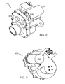
- FIGS. 2 and 3 are front and rear perspective views, respectively, of an exemplary physical embodiment of an actuator assembly that may be used in the system of FIG. 1 ;
- FIG. 4 is a cross section view of the actuator assembly depicted in FIGS. 2 and 3 ;
- FIG. 5 is a perspective view of the exemplary actuator assembly depicted in FIGS. 2 and 3 with the housing portions depicted in a ghosted manner;
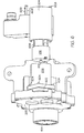
- FIG. 6 depicts the actuator assembly of FIGS. 2 and 3 in a partially disassembled state
- FIG. 7 depicts a close-up portion of a motor and actuator brake that make up the actuator assembly of FIGS. 2 and 3 .
- the system 100 includes a control circuit 102, a plurality of electric brake actuator assemblies 104, and a plurality of actuator brakes 106.
- the control circuit 102 receives brake command signals that are representative of a desired brake force.
- the brake command signals are supplied from, for example, brake pedal transducers 108 that are coupled to brake pedals 110 located in an aircraft cockpit 111.
- the brake pedal transducers 108 are preferably implemented using position sensors, which provide position signals representative of the position of the brake pedals 110.
- the control circuit 102 uses the position signals and the known spring rate of a return spring (not illustrated) coupled to the brake pedals 110, calculates the application force a pilot is supplying to the brake pedals 110.
- the brake pedal transducers 108 may be implemented using any one of numerous types of position sensors. In a particular embodiment, LVDT (linear variable differential transformer) position sensors are used. Moreover, other types of sensors, such as force sensors, could also be used if desired.
- the control circuit 102 also receives one or more signals representative of aircraft operational state.
- the number and type of sensors used to supply the one or more signals representative of operational state may vary.
- the sensors include one or more wheel speed sensors 112, one or more weight-on-wheels sensors 114, and one or more throttle position sensors 116.
- the one or more wheel speed sensors 112 are each configured to sense the rotational speed of an aircraft wheel 132 and supply a wheel speed signal representative thereof.
- the one or more weight-on-wheels sensors 114 are each configured to sense when the aircraft is on the ground (or other surface) and supply a signal representative thereof.
- the one or more engine throttle position sensors 116 are each configured to sense the position of the aircraft engine throttle and supply an engine throttle position signal representative thereof. It will be appreciated that the wheel speed sensors 112, the weight-on-wheels sensors 114, and the engine throttle position sensors 116 may be implemented using any one of numerous types of sensors .
- the control circuit 102 is configured to process the brake command signals supplied from the brake pedal transducers 108, and controllably energize the electric brake actuator assemblies 104 to move to a brake position that corresponds to the commanded brake force.
- the control circuit 102 is also configured to process the brake command signals to determine when the brake pedal application force supplied from the pilot exceeds a set force magnitude and, upon exceeding the set force magnitude, when the brake pedal application force is less than a reset force magnitude.
- the control circuit 102 is additionally configured to process the one or more signals representative of aircraft operational state to determine when the aircraft is in a ground-idle state.
- the control circuit 102 selectively supplies actuator brake commands to the actuator brakes 106 and selectively de-energizes and re-energizes the electric brake actuator assemblies 104. This latter functionality will be described in more detail further below.
- ground-idle state means that the aircraft is on the ground (or other surface), the aircraft is stationary (or at least moving at less than a predetermined speed), and the aircraft engines are in an idle running state.
- the engines may be in an idle running state when, for example, the engine throttles are positioned to a ground-idle position. It will be appreciated, however, that various other engine throttle positions could be used to indicate that the aircraft engines are in an idle running state.
- control circuit 102 may be variously configured to implement the functionality described above.
- the control circuit 102 includes a plurality of brake controls 122 and a plurality of actuator controls 124.
- Each brake control 122 is coupled to receive the one or more operational state signals and the brake command signals and is configured, in response to these signals, to supply actuator commands, the friction brake commands, and power enable/disable commands.
- the brake controls 122 translate the calculated brake pedal application forces to command force levels for the electric brake actuator assemblies 104.
- the control circuit 102 includes two brake controls 122-1, 122-2 to provide suitable redundancy. It will be appreciated, however, that the control circuit 102 could be implemented with more or less than this number of brake controls 122.
- the actuator controls 124 are each coupled to receive the actuator commands and are each configured, in response to the actuator commands, to controllably energize a plurality of the electric brake actuator assemblies 104 to move to a brake position that corresponds to the commanded brake force.
- the control circuit 102 includes two multi-channel actuator controls 124-1, 124-2 to provide suitable redundancy.
- the number of channels in each actuator control 124 may vary depending, for example, on the number of electric brake actuator assemblies 104. This is because each channel in an actuator control 124 is preferably associated a single electric brake actuator 104.
- the system 100 is configured to be used with an aircraft that includes a left landing gear 126 and a right landing gear 128, with each landing gear having two wheels 132 - an inboard wheel and an outboard wheel.
- the system 100 is additionally configured so that four electric brake actuator assemblies 104 are associated with each wheel 132, and all four of the electric brake actuator assemblies 104 associated with the same wheel 132 apply a brake force to the same brake stack.
- the system 100 at least in the depicted embodiment, includes a total of sixteen electric brake actuator assemblies 104 and sixteen actuator brakes 106, and each actuator control 124 includes eight channels for a total of sixteen channels. It will be appreciated that this is merely exemplary of a particular embodiment, and that the system 100 could be configured to include more or less than this number of electric brake actuator assemblies 104 and actuator brakes 106 and, concomitantly, channels per actuator control 124.
- the system 100 provides further redundancy by, as depicted in FIG. 1 , coupling half of the electric brake actuator assemblies 104 associated with each wheel 132 to two channels in different actuator controls 124.
- the electric brake actuator assemblies 104 associated with the outboard wheel 132 of the left landing gear 126 are coupled to two independent channels in one actuator control 124-1, and the other two electric brake actuator assemblies 104 are coupled to two independent channels in the other actuator control 124-2. In this manner, even in the unlikely event one of the actuator controls 124 becomes inoperable, there will remain at least two operable electric brake actuator assemblies 104 associated with each wheel 132.
- control circuit 102 may be implemented using one or more general purpose processors, content addressable memory, digital signal processors, application specific integrated circuits, field programmable gate arrays, any suitable programmable logic devices, discrete gate or transistor logic, discrete hardware components, or any combination thereof, designed to perform the functions described herein.
- a processor may be realized as a microprocessor, a controller, a microcontroller, or a state machine.
- a processor may also be implemented as a combination of computing devices, e.g., a combination of a digital signal processor and a microprocessor, a plurality of microprocessors, one or more microprocessors in conjunction with a digital signal processor core, or any other such configuration.
- each electric brake actuator 104 is configured, upon being controllably energized, to move to a brake position that corresponds to the commanded brake force, to thereby supply the desired brake force to its associated wheel 132.
- the actuator brakes 106 are each configured, in response to the actuator brake commands supplied by the control circuit 102, to selectively move to an engage position or a disengage position to engage or disengage, respectively, one of the electric brake actuator assemblies 104. In the engage position, each actuator brake 106 holds its associated electric brake actuator assemblies 104 in the last commanded brake position.
- the system 100 may also include one or more power supplies (or power converters) 134.
- the power supplies 134 preferably provide electrical power to various portions of the control circuit 102, such as the actuator controls 124.
- the power supplies 134 are configured, in response to the power enable/disable signals supplied from the brake controls 122, to selectively remove electrical power from, and subsequently restore electrical power to, the actuator controls 124.
- the circumstances under which the control circuit 102 commands the power supplies 134 to remove electrical power from and subsequently restore electrical to the actuator controls 124 will be described in more detail further below.
- the actuator assembly 104 includes an actuator housing 202 and a removable motor housing 204.
- a motor 206 and an actuator brake 106 are disposed within the removable motor housing 204, and an actuator 402 (see FIG. 4 ) is disposed within the actuator housing 202.
- the motor 206 is configured to be controllably energized by one of the actuator controls 124 and, upon being energized, to rotate and supply a drive torque.
- the motor 206 may be any one of numerous types of electric motors.
- the motor 206 is implemented as a brushless DC motor. No matter the particular type of motor 206 that is used, the drive torque is supplied to the actuator 402, an embodiment of which, for completeness, will now be described.
- the actuator 402 includes a ballscrew 404 and a ballnut 406.
- the ballscrew 404 is rotationally mounted within the actuator housing 202 and includes a first end 414, a second end 416, an inner surface 418, and an outer surface 422.
- the ballscrew inner surface 418 defines a substantially cylindrical passageway 424 through the ballscrew 404, and has a plurality of ball grooves (or "threads") 426 formed thereon.
- the ballscrew 404 is coupled to receive the drive torque from the motor 206 and, in response thereto, to rotate.
- an input gear 428 is coupled to the ballscrew outer surface 422, and receives the drive torque, via a plurality of gears that are described further below, which in turn causes the ballscrew 404 to rotate.
- the ballscrew input gear 428 is shown disposed substantially centrally between the ballscrew first 414 and second 416 ends, it will be appreciated that this is merely exemplary of a particular preferred embodiment, and that the input gear could be coupled to other locations on the ballscrew outer surface 422, or to either the ballscrew first end 414 or second end 416.
- a plurality of roller bearing assemblies which includes a first roller bearing assembly 432 and a second roller bearing assembly 434, are mounted within the actuator housing 202 and are used to rotationally support the ballscrew 404 therein.
- a thrust bearing assembly 436 is preferably disposed between the actuator housing 202 and the ballscrew first end 414. The thrust bearing 436 transfers any axial force supplied to the ballscrew 404 to the actuator housing 202.
- the ballnut 406 is disposed at least partially within the ballscrew 404 and includes a first end 438 and a second end 442.
- An extension tube (or ram) 445 is coupled to the ballnut second end 442, and includes an inner surface 444, and an outer surface 446.
- the ballnut 406, and concomitantly the ram 445 are mounted against rotation within the actuator housing 202 and are configured, in response to rotation of the ballscrew 404, to translate axially within the ballscrew cylindrical passageway 424. It will be appreciated that the direction in which the ballnut 406 and ram 445 travel will depend on the direction in which the ballscrew 404 rotates.
- an anti-rotation shaft 448 is coupled to the actuator housing 202 and engages the ballnut 406 to prevent its rotation. It will be appreciated that the anti-rotation shaft 448 and ballnut 406 may be configured in any one of numerous ways to prevent ballnut rotation. In the depicted embodiment, the anti-rotation shaft 448 is disposed at least partially within a groove (not shown) formed in a portion of the ballnut inner surface 444, to thereby prevent its rotation.
- the ballnut 406 similar to the ballscrew 404, has a plurality of ball grooves (or “threads") 452 formed therein. However, unlike the ballscrew ball grooves 426, the ballnut ball grooves 452 are formed in the ballnut outer surface 446. A plurality of non-illustrated balls are disposed within the ballnut ball grooves 452, and in selected ones of the ballscrew ball grooves 426. The balls, in combination with the ball grooves 426, 452, convert the rotational movement of the ballscrew 404 into the translational movement of the ballnut 406 and ram 445.
- a pad 454 is coupled to the ram second end 442. The pad 454 engages an aircraft brake element (not shown) when the brake actuator 108 is commanded to an engage position.
- the drive torque of the motor 206 is supplied to the ballscrew 404 via a plurality of gears.
- the gears include a motor output gear 456, a first intermediate gear set 458, a second intermediate gear set 462, and the ballscrew input gear 428.
- the motor output gear 456 is coupled to the motor 206, and engages the first intermediate gear set 458.
- the motor output gear 456 receives the drive torque directly therefrom, and causes the first intermediate gear set 458 to rotate in response thereto.
- the first intermediate gear set 458 includes two gears, an input gear 457 and an output gear 459, and is rotationally mounted within the actuator housing 202 via third and fourth roller bearing assemblies 465 and 467, respectively.
- the first intermediate gear set input gear 457 engages the motor output gear 456, and the first intermediate gear set output gear 459 engages the second intermediate gear set 462.
- the second intermediate gear set 462 similar to the first intermediate gear set 458, is rotationally mounted and includes two gears. More specifically, the second intermediate gear set 462 is rotationally mounted in the actuator housing 202 via non-depicted fifth and sixth roller bearing assemblies, and includes an input gear 461 and an output gear 463.
- the second intermediate gear set input gear 461 engages the first intermediate gear set output gear 459, and the second intermediate gear set output gear 463 engages the ballscrew input gear 428.
- the first intermediate gear set 458 receives, via the motor output gear 456, the drive torque supplied by the motor 206.
- the first intermediate gear set 458 rotates, and supplies the drive torque to the second intermediate gear set 462.
- the second intermediate gear set 462 rotates and supplies the drive torque to the ballscrew input gear 428, which causes the ballscrew 404 to rotate.
- the gear ratio between the motor output gear 456 and the first intermediate gear set input gear 457 provides a first rotational speed reduction
- the gear ratio between the first intermediate gear set output gear 459 and the second intermediate gear set 462 provides a second rotational speed reduction.
- the individual and/or collective gear ratios and the concomitant individual and/or collective rotational speed reductions may vary to achieve a desired torque-speed characteristic for the brake actuator 108.
- the motor 206 and actuator brake 106 are disposed within the removable motor housing 204. More specifically, it is seen that the motor 206 is removably coupled to a mounting flange 602 on the actuator housing 202 via a plurality of motor mounting bolts 604. Moreover, the actuator brake 106 is removably coupled to the motor 206 via a plurality of actuator brake mounting bolts 606.
- the removable motor housing 204 envelopes at least a portion of the motor 206 and the actuator brake 106, and is removably coupled to the actuator housing 202 via a plurality of motor housing bolts 608.
- the removable motor housing 204 is also accessible when the actuator housing 202 is mounted on an aircraft landing gear. This configuration enables the actuator brake 106 to be removed and replaced in the field without the need for any special tools.
- the actuator brake 106 is configured to selectively move to an engage position or a disengage position to engage or disengage, respectively, the electric brake actuator assembly 104. More specifically, the brake actuator 106 is configured to selectively engage and disengage the motor 206 to thereby at least inhibit motor rotation and allow motor rotation, respectively.
- the depicted brake actuator 106 implements this functionality by selectively engaging and disengaging the motor shaft 612 (see FIG. 6 ), which extends from an end of the motor 206.
- the brake actuator 106 may be variously configured to implement its functionality, in the depicted embodiment, it is an electrically operated device that is configured to engage the motor shaft 612 when it is de-energized, and to disengage the motor shaft 612 when it is energized.
- the motor 206 and actuator brake 106 are not only mechanically coupled together, but are also electrically coupled together.
- an electric connector 702 extends from the motor 206 and a plurality of electrically conductive pins 704 extend from the actuator brake 106.
- the electrical connector 702 extends from the same end of the motor 206 as the motor shaft 612 and includes a plurality of receptacles 706.
- each one of the plurality of electrically conductive pins 704 is disposed within one of the receptacles.
- a plurality of actuator brake power conductors 708 may also extend from the electric connector 702 through the motor.
- the actuator brake power conductors 708 are configured to couple to a direct current (DC) electric power source such as, for example, one of the above-described actuator controls 124.
- DC direct current
- the electric connector 702 and electrically conductive pins 704 are depicted as being configured as female and male connective devices, respectively, it will be appreciated that this is merely exemplary, and that the opposite configuration could be used.
- the electric connector 702 could be disposed on the actuator brake 106 and the electrically conductive pins 704 could be disposed on the motor 206.
- the actuator assembly configuration described herein allows the motor housing 204 to be removed from the actuator housing 202, even when the actuator housing is installed on an aircraft.
- the disclosed configuration further allows the actuator brake 106 to be removed and replaced, if needed, without having to remove other actuator assembly components.
Landscapes
- Engineering & Computer Science (AREA)
- Mechanical Engineering (AREA)
- Transportation (AREA)
- General Engineering & Computer Science (AREA)
- Braking Arrangements (AREA)
- Regulating Braking Force (AREA)
Claims (7)
- Aktuatoranordnung (100) für elektrische Flugzeugbremse, die Folgendes umfasst:ein Aktuatorgehäuse (202), das konfiguriert ist, um an einem Flugzeugfahrwerk (126, 128) angebracht zu werden;ein Motorgehäuse (204), das mit dem Aktuatorgehäuse verbunden ist und hiervon abgenommen werden kann, wobei das Motorgehäuse zugänglich ist, wenn das Aktuatorgehäuse an einem Flugzeugfahrwerk angebracht ist;einen Aktuator, der in dem Aktuatorgehäuse angeordnet ist, wobei der Aktuator verbunden ist, um ein Antriebsmoment aufzunehmen, und konfiguriert ist, um sich bei Aufnahme des Antriebsmoments zu einer Position zu verschieben;einen Elektromotor, der in dem Motorgehäuse angeordnet und mit dem Aktuator verbunden ist, wobei der Elektromotor dazu ausgelegt ist, um wahlweise erregt zu werden, und konfiguriert ist, um sich bei Erregung zu drehen und dadurch das Antriebsmoment an den Aktuator zu liefern; gekennzeichnet durcheine Aktuatorbremse (106), die in dem Motorgehäuse angeordnet und abnehmbar mit dem Motor verbunden ist, wobei die Aktuatorbremse konfiguriert ist, um wahlweise mit dem Motor in Eingriff zu gelangen und diesen Eingriff zu lösen, um dadurch wenigstens eine Motordrehung zu verhindern bzw. zuzulassen.
- Aktuatoranordnung nach Anspruch 1, wobei der Elektromotor eine drehbar angebrachte Welle enthält und die Aktuatorbremse (106) wenigstens wahlweise an der Welle in Eingriff gelangt.
- Aktuatoranordnung nach Anspruch 2, wobei die Aktuatorbremse (106) elektrisch betätigt wird.
- Aktuatoranordnung nach Anspruch 2, die ferner Folgendes umfasst:einen elektrischen Verbinder (702), der sich vom Motor erstreckt; undmehrere elektrisch leitende Stifte (704), die sich von der Aktuatorbremse erstrecken und lösbar mit dem elektrischen Verbinder verbunden sind.
- Aktuatoranordnung nach Anspruch 4, wobei der Motor ein erstes Ende und ein zweites Ende enthält, wobei die Welle sich von dem ersten Ende erstreckt und der elektrische Verbinder (702) sich von dem zweiten Ende erstreckt.
- Aktuatoranordnung nach Anspruch 4, die ferner Folgendes enthält: mehrere Leistungsleiteinrichtungen der Aktuatorbremse, die sich durch den Motor zu dem elektrischen Verbinder (702) erstrecken, wobei die Leistungsleiteinrichtungen der Aktuatorbremse angepasst sind, um mit einer elektrischen Gleichstrom-Leistungsquelle (DC-Leistungsquelle) zu verbinden.
- Aktuatoranordnung nach Anspruch 3, wobei die Aktuatorbremse (106) konfiguriert ist, um mit dem Motor in Eingriff zu gelangen, wenn sie elektrisch aberregt wird, und den Eingriff mit dem Motor zu lösen, wenn sie elektrisch erregt wird.
Applications Claiming Priority (1)
| Application Number | Priority Date | Filing Date | Title |
|---|---|---|---|
| US12/704,971 US9815438B2 (en) | 2010-02-12 | 2010-02-12 | Aircraft electric brake actuator assembly with line replaceable actuator brake |
Publications (2)
| Publication Number | Publication Date |
|---|---|
| EP2360072A1 EP2360072A1 (de) | 2011-08-24 |
| EP2360072B1 true EP2360072B1 (de) | 2012-01-25 |
Family
ID=43983764
Family Applications (1)
| Application Number | Title | Priority Date | Filing Date |
|---|---|---|---|
| EP11152817A Active EP2360072B1 (de) | 2010-02-12 | 2011-01-31 | Betätigungsanordnung für elektrische Flugzeugbremse mit schnell auszuwechselnder Betätigungsbremse |
Country Status (3)
| Country | Link |
|---|---|
| US (1) | US9815438B2 (de) |
| EP (1) | EP2360072B1 (de) |
| AT (1) | ATE542716T1 (de) |
Families Citing this family (14)
| Publication number | Priority date | Publication date | Assignee | Title |
|---|---|---|---|---|
| GB0623804D0 (en) * | 2006-11-29 | 2007-01-10 | Dunlop Aerospace Ltd | A Braking system for an aircraft and a method of monitoring braking for an air |
| US8919504B2 (en) * | 2009-12-03 | 2014-12-30 | Honeywell International Inc. | Brake actuator assembly with line replaceable motor features |
| US9440735B2 (en) * | 2010-01-25 | 2016-09-13 | Honeywell International Inc. | Aircraft electric brake actuation system and method |
| GB201015510D0 (en) * | 2010-09-16 | 2010-10-27 | Goodrich Actuation Systems Sas | Power supply system |
| FR2968274B1 (fr) * | 2010-12-06 | 2013-02-01 | Messier Bugatti | Dispositif de freinage/entrainement d'une roue d'aeronef. |
| JP2013072511A (ja) * | 2011-09-28 | 2013-04-22 | Hitachi Automotive Systems Ltd | ディスクブレーキ |
| DE102012009106A1 (de) * | 2012-04-27 | 2013-10-31 | Liebherr-Aerospace Lindenberg Gmbh | Aktuator für ein Fahrwerk eines Luftfahrzeuges |
| FR2992288B1 (fr) * | 2012-06-25 | 2015-03-06 | Messier Bugatti Dowty | Procede de deblocage d'un frein de roue d'aeronef |
| FR2992942B1 (fr) * | 2012-07-09 | 2015-03-06 | Messier Bugatti Dowty | Procede d'utilisation et de maintenance d'un frein d'atterrisseur comprenant une pile de disques actionneur de frein, frein d'aeronef et ensemble roue-frein comportant un tel actionneur |
| US8666625B1 (en) | 2012-11-13 | 2014-03-04 | Hamilton Sundstrand Corporation | Automatic adjustment of electric brake actuators for a dragging brake condition |
| US9815551B2 (en) | 2015-07-20 | 2017-11-14 | Goodrich Corporation | Systems and methods for aircraft braking and taxiing |
| US10584754B2 (en) * | 2017-09-19 | 2020-03-10 | Whippany Actuation Systems Llc | Line replaceable brake |
| US11702193B1 (en) | 2022-04-28 | 2023-07-18 | Beta Air, Llc | Systems and methods for an electric vertical takeoff and landing aircraft braking system |
| KR102653359B1 (ko) * | 2022-06-21 | 2024-04-02 | 한국항공우주연구원 | 이중화 작동기 및 그 제어 방법 |
Family Cites Families (36)
| Publication number | Priority date | Publication date | Assignee | Title |
|---|---|---|---|---|
| US571708A (en) | 1896-11-17 | Dust-guard for air-brake hose-couplings | ||
| US2510114A (en) * | 1946-02-08 | 1950-06-06 | Fred E Hummel | Drill pipe wiper |
| US2528332A (en) * | 1947-07-03 | 1950-10-31 | Electrolux Corp | Self-acting closure |
| US2725123A (en) * | 1952-05-19 | 1955-11-29 | Frank E Reuland | Magnetic brake |
| GB775052A (en) | 1954-05-03 | 1957-05-15 | Roy Selden Sanford | Cooling arrangement for brake mechanism |
| US3401867A (en) * | 1967-03-16 | 1968-09-17 | Continental Can Co | Self-closing dust valve for a disposable vacuum cleaner bag |
| US3834718A (en) * | 1973-02-15 | 1974-09-10 | Ingersoll Rand Co | Sealing means |
| US4042248A (en) * | 1976-09-16 | 1977-08-16 | General Motors Corporation | High pressure shaft seals |
| US4430592A (en) * | 1981-08-31 | 1984-02-07 | Tape Research, Inc. | Electromagnetic brake |
| US4865162A (en) * | 1986-12-15 | 1989-09-12 | Opus Acquisition Corporation | Electrically actuated aircraft brakes |
| US5005767A (en) * | 1989-08-24 | 1991-04-09 | L.R. Nelson Corporation | Slitted dirt seal for inground sprinkler heads |
| US5111854A (en) * | 1991-03-01 | 1992-05-12 | Mobil Oil Corporation | Particle movement system with control of dust |
| US5400885A (en) * | 1993-03-08 | 1995-03-28 | Reliance Electric Industrial Company | Retained key shaft mounting assembly |
| US5497860A (en) * | 1994-08-15 | 1996-03-12 | Venturedyne Limited | Electromagnetic brake with improved magnet structure |
| DE19752543A1 (de) * | 1997-11-27 | 1999-06-02 | Bosch Gmbh Robert | Magnetbremse und elektromechanische Bremsvorrichtung mit einer Magnetbremse |
| US6095293A (en) | 1998-02-13 | 2000-08-01 | The B. F. Goodrich Company | Aircraft brake and method with electromechanical actuator modules |
| WO2001020188A1 (en) * | 1999-09-13 | 2001-03-22 | The B.F.Goodrich Company | Electric brake actuator module for aircraft |
| US6581730B1 (en) | 1999-09-13 | 2003-06-24 | Goodrich Corporation | Aircraft landing gear with integrated brake actuation system |
| US6559566B2 (en) * | 2001-02-12 | 2003-05-06 | Emerson Electric Co. | End shield constructed with a separate component holder |
| DE10109320C2 (de) * | 2001-02-27 | 2003-07-10 | Bruss Dichtungstechnik | Radialwellendichtring |
| FR2824967A1 (fr) | 2001-05-16 | 2002-11-22 | Sagem | Actionneur lineaire, notamment actionneur pour frein d'avion |
| DE10160848A1 (de) * | 2001-12-12 | 2003-07-17 | Valeo Auto Electric Gmbh | Antriebs- und/oder Abbremsvorrichtung |
| ITTO20011164A1 (it) * | 2001-12-13 | 2003-06-13 | Skf Ind Spa | Attuatore a vite con freno. |
| US6852061B2 (en) * | 2002-09-30 | 2005-02-08 | Benjamin Warren Schoon | Planetary gearbox with integral electric motor and steering means. |
| US7717240B2 (en) | 2003-04-30 | 2010-05-18 | Goodrich Corporation | Electric brake for aircraft |
| FR2862280B1 (fr) * | 2003-11-14 | 2006-03-03 | Messier Bugatti | Atterrisseur, frein pour roue d'aeronef, ensemble de roue freinee d'aeronef, et procede de maintenance d'un tel atterrisseur |
| US20050247529A1 (en) * | 2004-05-07 | 2005-11-10 | Gaines Louie T | Aircraft brake acuation system including an internally threaded ballscrew actuator assembly |
| EP1766256B1 (de) | 2004-06-04 | 2010-09-15 | Goodrich Corporation | Elektrische bremse für luftfahrzeug |
| DE602005019563D1 (de) * | 2004-06-04 | 2010-04-08 | Goodrich Corp | Messung und steuerung von position und kraft bei elektrischen bremsen |
| FR2877411B1 (fr) | 2004-10-28 | 2007-02-09 | Messier Bugatti Sa | Actionneur electromecanique pour frein de vehicule, frein comportant un tel actionneur et procede de maintenance d'un tel frein |
| US8641154B2 (en) * | 2006-10-09 | 2014-02-04 | The Boeing Company | Parking brake adjustment for an aircraft having an electric brake system |
| US20080110435A1 (en) * | 2006-11-13 | 2008-05-15 | Oswald Baasch | Air valve and method of use |
| US8296916B2 (en) | 2007-05-21 | 2012-10-30 | Goodrich Corporation | Repair method for electric aircraft brake |
| EP2060821A1 (de) | 2007-11-14 | 2009-05-20 | Goodrich Corporation | Flugzeugbremse und Verfahren mit elektromechanischen Aktuatormodulen |
| US7960881B2 (en) * | 2008-10-15 | 2011-06-14 | Nidec Motor Corporation | Electric motor having drainage means |
| US8919504B2 (en) * | 2009-12-03 | 2014-12-30 | Honeywell International Inc. | Brake actuator assembly with line replaceable motor features |
-
2010
- 2010-02-12 US US12/704,971 patent/US9815438B2/en active Active
-
2011
- 2011-01-31 AT AT11152817T patent/ATE542716T1/de active
- 2011-01-31 EP EP11152817A patent/EP2360072B1/de active Active
Also Published As
| Publication number | Publication date |
|---|---|
| US20110198163A1 (en) | 2011-08-18 |
| EP2360072A1 (de) | 2011-08-24 |
| US9815438B2 (en) | 2017-11-14 |
| ATE542716T1 (de) | 2012-02-15 |
Similar Documents
| Publication | Publication Date | Title |
|---|---|---|
| EP2360072B1 (de) | Betätigungsanordnung für elektrische Flugzeugbremse mit schnell auszuwechselnder Betätigungsbremse | |
| EP2330312B1 (de) | Bremsenbetätigungsvorrichtung mit vor Ort austauschbaren Motoren | |
| US10066715B2 (en) | Fail-safe electromechanical actuator | |
| EP2353951B1 (de) | Elektrisches Flugzeugbremsenbetätigungssystem und -verfahren | |
| EP3779227B1 (de) | Elektrische parkbremse für bremssattel mit mehreren kolben | |
| US4745815A (en) | Non-jamming screw actuator system | |
| CN104670482B (zh) | 蜗轮蜗杆式飞机电刹车系统及工作方法 | |
| CN107444380B (zh) | 一种集成式线控液压制动装置 | |
| US8322242B2 (en) | Velocity summing linear actuator | |
| US20040200928A1 (en) | Actuator and flap arrangement with actuator interconnection | |
| CN104595451A (zh) | 一种双输入通道差速器式机电作动器 | |
| US20050247529A1 (en) | Aircraft brake acuation system including an internally threaded ballscrew actuator assembly | |
| US20250146563A1 (en) | Fault tolerant rotary ema | |
| CN204527620U (zh) | 蜗轮蜗杆式飞机电刹车系统 | |
| EP3153735B1 (de) | Zusätzliches bremssystem | |
| CN1980010B (zh) | 容错机电致动器 | |
| US7093696B2 (en) | Aircraft brake actuator thermal insulator and tangential movement compensator | |
| US8794394B2 (en) | Electric brake system with flexible force transfer member |
Legal Events
| Date | Code | Title | Description |
|---|---|---|---|
| PUAI | Public reference made under article 153(3) epc to a published international application that has entered the european phase |
Free format text: ORIGINAL CODE: 0009012 |
|
| 17P | Request for examination filed |
Effective date: 20110131 |
|
| AK | Designated contracting states |
Kind code of ref document: A1 Designated state(s): AL AT BE BG CH CY CZ DE DK EE ES FI FR GB GR HR HU IE IS IT LI LT LU LV MC MK MT NL NO PL PT RO RS SE SI SK SM TR |
|
| AX | Request for extension of the european patent |
Extension state: BA ME |
|
| GRAP | Despatch of communication of intention to grant a patent |
Free format text: ORIGINAL CODE: EPIDOSNIGR1 |
|
| RIC1 | Information provided on ipc code assigned before grant |
Ipc: B64C 25/44 20060101ALI20110825BHEP Ipc: B60T 7/04 20060101AFI20110825BHEP Ipc: B60T 8/17 20060101ALI20110825BHEP Ipc: B60T 8/32 20060101ALI20110825BHEP Ipc: F16D 65/00 20060101ALI20110825BHEP Ipc: B60T 13/74 20060101ALI20110825BHEP Ipc: F16D 65/14 20060101ALI20110825BHEP |
|
| GRAS | Grant fee paid |
Free format text: ORIGINAL CODE: EPIDOSNIGR3 |
|
| GRAA | (expected) grant |
Free format text: ORIGINAL CODE: 0009210 |
|
| AK | Designated contracting states |
Kind code of ref document: B1 Designated state(s): AL AT BE BG CH CY CZ DE DK EE ES FI FR GB GR HR HU IE IS IT LI LT LU LV MC MK MT NL NO PL PT RO RS SE SI SK SM TR |
|
| REG | Reference to a national code |
Ref country code: GB Ref legal event code: FG4D |
|
| REG | Reference to a national code |
Ref country code: CH Ref legal event code: EP |
|
| REG | Reference to a national code |
Ref country code: AT Ref legal event code: REF Ref document number: 542716 Country of ref document: AT Kind code of ref document: T Effective date: 20120215 |
|
| REG | Reference to a national code |
Ref country code: IE Ref legal event code: FG4D |
|
| REG | Reference to a national code |
Ref country code: DE Ref legal event code: R096 Ref document number: 602011000001 Country of ref document: DE Effective date: 20120329 |
|
| REG | Reference to a national code |
Ref country code: NL Ref legal event code: VDEP Effective date: 20120125 |
|
| LTIE | Lt: invalidation of european patent or patent extension |
Effective date: 20120125 |
|
| PG25 | Lapsed in a contracting state [announced via postgrant information from national office to epo] |
Ref country code: NL Free format text: LAPSE BECAUSE OF FAILURE TO SUBMIT A TRANSLATION OF THE DESCRIPTION OR TO PAY THE FEE WITHIN THE PRESCRIBED TIME-LIMIT Effective date: 20120125 Ref country code: BG Free format text: LAPSE BECAUSE OF FAILURE TO SUBMIT A TRANSLATION OF THE DESCRIPTION OR TO PAY THE FEE WITHIN THE PRESCRIBED TIME-LIMIT Effective date: 20120425 Ref country code: LT Free format text: LAPSE BECAUSE OF FAILURE TO SUBMIT A TRANSLATION OF THE DESCRIPTION OR TO PAY THE FEE WITHIN THE PRESCRIBED TIME-LIMIT Effective date: 20120125 Ref country code: HR Free format text: LAPSE BECAUSE OF FAILURE TO SUBMIT A TRANSLATION OF THE DESCRIPTION OR TO PAY THE FEE WITHIN THE PRESCRIBED TIME-LIMIT Effective date: 20120125 Ref country code: BE Free format text: LAPSE BECAUSE OF FAILURE TO SUBMIT A TRANSLATION OF THE DESCRIPTION OR TO PAY THE FEE WITHIN THE PRESCRIBED TIME-LIMIT Effective date: 20120125 Ref country code: NO Free format text: LAPSE BECAUSE OF FAILURE TO SUBMIT A TRANSLATION OF THE DESCRIPTION OR TO PAY THE FEE WITHIN THE PRESCRIBED TIME-LIMIT Effective date: 20120425 Ref country code: IS Free format text: LAPSE BECAUSE OF FAILURE TO SUBMIT A TRANSLATION OF THE DESCRIPTION OR TO PAY THE FEE WITHIN THE PRESCRIBED TIME-LIMIT Effective date: 20120525 |
|
| PG25 | Lapsed in a contracting state [announced via postgrant information from national office to epo] |
Ref country code: PT Free format text: LAPSE BECAUSE OF FAILURE TO SUBMIT A TRANSLATION OF THE DESCRIPTION OR TO PAY THE FEE WITHIN THE PRESCRIBED TIME-LIMIT Effective date: 20120525 Ref country code: LV Free format text: LAPSE BECAUSE OF FAILURE TO SUBMIT A TRANSLATION OF THE DESCRIPTION OR TO PAY THE FEE WITHIN THE PRESCRIBED TIME-LIMIT Effective date: 20120125 Ref country code: GR Free format text: LAPSE BECAUSE OF FAILURE TO SUBMIT A TRANSLATION OF THE DESCRIPTION OR TO PAY THE FEE WITHIN THE PRESCRIBED TIME-LIMIT Effective date: 20120426 Ref country code: MC Free format text: LAPSE BECAUSE OF NON-PAYMENT OF DUE FEES Effective date: 20120131 Ref country code: PL Free format text: LAPSE BECAUSE OF FAILURE TO SUBMIT A TRANSLATION OF THE DESCRIPTION OR TO PAY THE FEE WITHIN THE PRESCRIBED TIME-LIMIT Effective date: 20120125 Ref country code: FI Free format text: LAPSE BECAUSE OF FAILURE TO SUBMIT A TRANSLATION OF THE DESCRIPTION OR TO PAY THE FEE WITHIN THE PRESCRIBED TIME-LIMIT Effective date: 20120125 |
|
| REG | Reference to a national code |
Ref country code: AT Ref legal event code: MK05 Ref document number: 542716 Country of ref document: AT Kind code of ref document: T Effective date: 20120125 |
|
| PG25 | Lapsed in a contracting state [announced via postgrant information from national office to epo] |
Ref country code: CY Free format text: LAPSE BECAUSE OF FAILURE TO SUBMIT A TRANSLATION OF THE DESCRIPTION OR TO PAY THE FEE WITHIN THE PRESCRIBED TIME-LIMIT Effective date: 20120125 |
|
| PG25 | Lapsed in a contracting state [announced via postgrant information from national office to epo] |
Ref country code: EE Free format text: LAPSE BECAUSE OF FAILURE TO SUBMIT A TRANSLATION OF THE DESCRIPTION OR TO PAY THE FEE WITHIN THE PRESCRIBED TIME-LIMIT Effective date: 20120125 Ref country code: RO Free format text: LAPSE BECAUSE OF FAILURE TO SUBMIT A TRANSLATION OF THE DESCRIPTION OR TO PAY THE FEE WITHIN THE PRESCRIBED TIME-LIMIT Effective date: 20120125 Ref country code: DK Free format text: LAPSE BECAUSE OF FAILURE TO SUBMIT A TRANSLATION OF THE DESCRIPTION OR TO PAY THE FEE WITHIN THE PRESCRIBED TIME-LIMIT Effective date: 20120125 Ref country code: SI Free format text: LAPSE BECAUSE OF FAILURE TO SUBMIT A TRANSLATION OF THE DESCRIPTION OR TO PAY THE FEE WITHIN THE PRESCRIBED TIME-LIMIT Effective date: 20120125 Ref country code: SE Free format text: LAPSE BECAUSE OF FAILURE TO SUBMIT A TRANSLATION OF THE DESCRIPTION OR TO PAY THE FEE WITHIN THE PRESCRIBED TIME-LIMIT Effective date: 20120125 Ref country code: CZ Free format text: LAPSE BECAUSE OF FAILURE TO SUBMIT A TRANSLATION OF THE DESCRIPTION OR TO PAY THE FEE WITHIN THE PRESCRIBED TIME-LIMIT Effective date: 20120125 |
|
| PG25 | Lapsed in a contracting state [announced via postgrant information from national office to epo] |
Ref country code: SK Free format text: LAPSE BECAUSE OF FAILURE TO SUBMIT A TRANSLATION OF THE DESCRIPTION OR TO PAY THE FEE WITHIN THE PRESCRIBED TIME-LIMIT Effective date: 20120125 Ref country code: IT Free format text: LAPSE BECAUSE OF FAILURE TO SUBMIT A TRANSLATION OF THE DESCRIPTION OR TO PAY THE FEE WITHIN THE PRESCRIBED TIME-LIMIT Effective date: 20120125 |
|
| PLBE | No opposition filed within time limit |
Free format text: ORIGINAL CODE: 0009261 |
|
| STAA | Information on the status of an ep patent application or granted ep patent |
Free format text: STATUS: NO OPPOSITION FILED WITHIN TIME LIMIT |
|
| 26N | No opposition filed |
Effective date: 20121026 |
|
| PG25 | Lapsed in a contracting state [announced via postgrant information from national office to epo] |
Ref country code: AT Free format text: LAPSE BECAUSE OF FAILURE TO SUBMIT A TRANSLATION OF THE DESCRIPTION OR TO PAY THE FEE WITHIN THE PRESCRIBED TIME-LIMIT Effective date: 20120125 |
|
| REG | Reference to a national code |
Ref country code: DE Ref legal event code: R097 Ref document number: 602011000001 Country of ref document: DE Effective date: 20121026 |
|
| PG25 | Lapsed in a contracting state [announced via postgrant information from national office to epo] |
Ref country code: RS Free format text: LAPSE BECAUSE OF FAILURE TO SUBMIT A TRANSLATION OF THE DESCRIPTION OR TO PAY THE FEE WITHIN THE PRESCRIBED TIME-LIMIT Effective date: 20120125 |
|
| REG | Reference to a national code |
Ref country code: IE Ref legal event code: MM4A |
|
| PG25 | Lapsed in a contracting state [announced via postgrant information from national office to epo] |
Ref country code: ES Free format text: LAPSE BECAUSE OF FAILURE TO SUBMIT A TRANSLATION OF THE DESCRIPTION OR TO PAY THE FEE WITHIN THE PRESCRIBED TIME-LIMIT Effective date: 20120506 |
|
| PG25 | Lapsed in a contracting state [announced via postgrant information from national office to epo] |
Ref country code: IE Free format text: LAPSE BECAUSE OF NON-PAYMENT OF DUE FEES Effective date: 20130131 Ref country code: AL Free format text: LAPSE BECAUSE OF FAILURE TO SUBMIT A TRANSLATION OF THE DESCRIPTION OR TO PAY THE FEE WITHIN THE PRESCRIBED TIME-LIMIT Effective date: 20120125 |
|
| PG25 | Lapsed in a contracting state [announced via postgrant information from national office to epo] |
Ref country code: TR Free format text: LAPSE BECAUSE OF FAILURE TO SUBMIT A TRANSLATION OF THE DESCRIPTION OR TO PAY THE FEE WITHIN THE PRESCRIBED TIME-LIMIT Effective date: 20120125 |
|
| PG25 | Lapsed in a contracting state [announced via postgrant information from national office to epo] |
Ref country code: HU Free format text: LAPSE BECAUSE OF FAILURE TO SUBMIT A TRANSLATION OF THE DESCRIPTION OR TO PAY THE FEE WITHIN THE PRESCRIBED TIME-LIMIT Effective date: 20110131 Ref country code: MT Free format text: LAPSE BECAUSE OF FAILURE TO SUBMIT A TRANSLATION OF THE DESCRIPTION OR TO PAY THE FEE WITHIN THE PRESCRIBED TIME-LIMIT Effective date: 20120125 |
|
| REG | Reference to a national code |
Ref country code: CH Ref legal event code: PL |
|
| PG25 | Lapsed in a contracting state [announced via postgrant information from national office to epo] |
Ref country code: LI Free format text: LAPSE BECAUSE OF NON-PAYMENT OF DUE FEES Effective date: 20140131 Ref country code: CH Free format text: LAPSE BECAUSE OF NON-PAYMENT OF DUE FEES Effective date: 20140131 |
|
| PG25 | Lapsed in a contracting state [announced via postgrant information from national office to epo] |
Ref country code: SM Free format text: LAPSE BECAUSE OF FAILURE TO SUBMIT A TRANSLATION OF THE DESCRIPTION OR TO PAY THE FEE WITHIN THE PRESCRIBED TIME-LIMIT Effective date: 20120125 |
|
| PG25 | Lapsed in a contracting state [announced via postgrant information from national office to epo] |
Ref country code: LU Free format text: LAPSE BECAUSE OF NON-PAYMENT OF DUE FEES Effective date: 20120131 Ref country code: MK Free format text: LAPSE BECAUSE OF FAILURE TO SUBMIT A TRANSLATION OF THE DESCRIPTION OR TO PAY THE FEE WITHIN THE PRESCRIBED TIME-LIMIT Effective date: 20120125 |
|
| REG | Reference to a national code |
Ref country code: FR Ref legal event code: PLFP Year of fee payment: 6 |
|
| REG | Reference to a national code |
Ref country code: FR Ref legal event code: PLFP Year of fee payment: 7 |
|
| REG | Reference to a national code |
Ref country code: FR Ref legal event code: PLFP Year of fee payment: 8 |
|
| P01 | Opt-out of the competence of the unified patent court (upc) registered |
Effective date: 20230525 |
|
| PGFP | Annual fee paid to national office [announced via postgrant information from national office to epo] |
Ref country code: GB Payment date: 20260126 Year of fee payment: 16 |
|
| PGFP | Annual fee paid to national office [announced via postgrant information from national office to epo] |
Ref country code: DE Payment date: 20260127 Year of fee payment: 16 |
|
| PGFP | Annual fee paid to national office [announced via postgrant information from national office to epo] |
Ref country code: FR Payment date: 20260127 Year of fee payment: 16 |