EP2359899A1 - Elektrodenvorrichtung für aktive medizinische Implantate - Google Patents
Elektrodenvorrichtung für aktive medizinische Implantate Download PDFInfo
- Publication number
- EP2359899A1 EP2359899A1 EP11153008A EP11153008A EP2359899A1 EP 2359899 A1 EP2359899 A1 EP 2359899A1 EP 11153008 A EP11153008 A EP 11153008A EP 11153008 A EP11153008 A EP 11153008A EP 2359899 A1 EP2359899 A1 EP 2359899A1
- Authority
- EP
- European Patent Office
- Prior art keywords
- electrode device
- coil
- capacitor
- ltcc
- electrode
- Prior art date
- Legal status (The legal status is an assumption and is not a legal conclusion. Google has not performed a legal analysis and makes no representation as to the accuracy of the status listed.)
- Granted
Links
- 239000007943 implant Substances 0.000 title claims description 7
- 239000003990 capacitor Substances 0.000 claims description 29
- 239000000758 substrate Substances 0.000 claims description 23
- 239000000919 ceramic Substances 0.000 claims description 13
- 238000005516 engineering process Methods 0.000 claims description 13
- 239000002184 metal Substances 0.000 claims description 13
- 239000003989 dielectric material Substances 0.000 claims description 9
- 239000000853 adhesive Substances 0.000 claims description 3
- 238000004026 adhesive bonding Methods 0.000 claims description 3
- 230000001070 adhesive effect Effects 0.000 claims description 3
- 238000005476 soldering Methods 0.000 claims description 3
- 238000003466 welding Methods 0.000 claims description 3
- 239000000523 sample Substances 0.000 abstract 5
- 230000001419 dependent effect Effects 0.000 abstract 1
- 238000002595 magnetic resonance imaging Methods 0.000 description 6
- 238000000034 method Methods 0.000 description 5
- 239000004020 conductor Substances 0.000 description 4
- 230000000747 cardiac effect Effects 0.000 description 3
- 210000005003 heart tissue Anatomy 0.000 description 3
- 230000010354 integration Effects 0.000 description 3
- 238000001465 metallisation Methods 0.000 description 3
- 210000001519 tissue Anatomy 0.000 description 3
- 230000002349 favourable effect Effects 0.000 description 2
- 238000010438 heat treatment Methods 0.000 description 2
- 230000006698 induction Effects 0.000 description 2
- 230000001939 inductive effect Effects 0.000 description 2
- 239000000463 material Substances 0.000 description 2
- 229920001296 polysiloxane Polymers 0.000 description 2
- 230000015572 biosynthetic process Effects 0.000 description 1
- 210000005242 cardiac chamber Anatomy 0.000 description 1
- 238000010276 construction Methods 0.000 description 1
- 230000006735 deficit Effects 0.000 description 1
- 238000002405 diagnostic procedure Methods 0.000 description 1
- 238000010586 diagram Methods 0.000 description 1
- 230000005674 electromagnetic induction Effects 0.000 description 1
- 238000001914 filtration Methods 0.000 description 1
- 238000009434 installation Methods 0.000 description 1
- 238000004519 manufacturing process Methods 0.000 description 1
- 230000002093 peripheral effect Effects 0.000 description 1
- 238000007650 screen-printing Methods 0.000 description 1
- 230000003068 static effect Effects 0.000 description 1
- 230000000638 stimulation Effects 0.000 description 1
- 230000001225 therapeutic effect Effects 0.000 description 1
Images


Classifications
-
- A—HUMAN NECESSITIES
- A61—MEDICAL OR VETERINARY SCIENCE; HYGIENE
- A61N—ELECTROTHERAPY; MAGNETOTHERAPY; RADIATION THERAPY; ULTRASOUND THERAPY
- A61N1/00—Electrotherapy; Circuits therefor
- A61N1/02—Details
- A61N1/04—Electrodes
- A61N1/05—Electrodes for implantation or insertion into the body, e.g. heart electrode
-
- H—ELECTRICITY
- H03—ELECTRONIC CIRCUITRY
- H03H—IMPEDANCE NETWORKS, e.g. RESONANT CIRCUITS; RESONATORS
- H03H1/00—Constructional details of impedance networks whose electrical mode of operation is not specified or applicable to more than one type of network
- H03H1/0007—Constructional details of impedance networks whose electrical mode of operation is not specified or applicable to more than one type of network of radio frequency interference filters
-
- H—ELECTRICITY
- H03—ELECTRONIC CIRCUITRY
- H03H—IMPEDANCE NETWORKS, e.g. RESONANT CIRCUITS; RESONATORS
- H03H7/00—Multiple-port networks comprising only passive electrical elements as network components
- H03H7/01—Frequency selective two-port networks
- H03H7/0115—Frequency selective two-port networks comprising only inductors and capacitors
-
- H—ELECTRICITY
- H03—ELECTRONIC CIRCUITRY
- H03H—IMPEDANCE NETWORKS, e.g. RESONANT CIRCUITS; RESONATORS
- H03H7/00—Multiple-port networks comprising only passive electrical elements as network components
- H03H7/01—Frequency selective two-port networks
- H03H7/17—Structural details of sub-circuits of frequency selective networks
- H03H7/1741—Comprising typical LC combinations, irrespective of presence and location of additional resistors
- H03H7/1766—Parallel LC in series path
-
- A—HUMAN NECESSITIES
- A61—MEDICAL OR VETERINARY SCIENCE; HYGIENE
- A61N—ELECTROTHERAPY; MAGNETOTHERAPY; RADIATION THERAPY; ULTRASOUND THERAPY
- A61N1/00—Electrotherapy; Circuits therefor
- A61N1/02—Details
- A61N1/08—Arrangements or circuits for monitoring, protecting, controlling or indicating
- A61N1/086—Magnetic resonance imaging [MRI] compatible leads
-
- G—PHYSICS
- G01—MEASURING; TESTING
- G01R—MEASURING ELECTRIC VARIABLES; MEASURING MAGNETIC VARIABLES
- G01R33/00—Arrangements or instruments for measuring magnetic variables
- G01R33/20—Arrangements or instruments for measuring magnetic variables involving magnetic resonance
- G01R33/28—Details of apparatus provided for in groups G01R33/44 - G01R33/64
- G01R33/288—Provisions within MR facilities for enhancing safety during MR, e.g. reduction of the specific absorption rate [SAR], detection of ferromagnetic objects in the scanner room
-
- H—ELECTRICITY
- H03—ELECTRONIC CIRCUITRY
- H03H—IMPEDANCE NETWORKS, e.g. RESONANT CIRCUITS; RESONATORS
- H03H1/00—Constructional details of impedance networks whose electrical mode of operation is not specified or applicable to more than one type of network
- H03H2001/0021—Constructional details
- H03H2001/0085—Multilayer, e.g. LTCC, HTCC, green sheets
Definitions
- the invention relates to an active medical implant electrode device comprising an elongated electrode body having a proximal and a distal end, a tip contact pole at the distal end, and / or a ring contact pole in front of the distal end, electrical leads to the tip or ring -Kontaktpol and one consisting of one or more electronic components high-frequency filter in at least one of the leads, which is assigned to the tip or ring contact pole.
- the subject invention is primarily relevant in the context of cardiac pacemakers, implantable defibrillators, and other types of active implantable electromedical devices.
- the latter usually have at least one current / voltage-carrying lead in the electrode device-usually referred to as "electrode” for short-whose distal end is arranged, for example, in a heart chamber and serves to measure cardiac potential signals or to deliver corresponding therapeutic current signals.
- MRI magnetic resonance imaging
- This alternating magnetic field leads according to the laws of electromagnetic induction in the lead of the electrode devices in question of electromedical device implants to AC voltages whose energy is converted in particular to the electrically conductive contact poles of the electrode device to human tissue into heat. This can result in significant heating of, for example, the tip contact of a cardiac electrode with a corresponding impairment and even damage to the cardiac tissue in contact or surrounding it.
- filter components for reducing the heating of pacemaker electrodes of an electromedical implant upon exposure to high frequency magnetic fields due to MRI procedures are known, wherein an induction coil is applied around a nonconductive, central portion of a shaft having a tip contact pole with an internal contact Spiral conductor of the electrode device connects.
- an induction coil By mounting an induction coil on the shaft, inductive signal filtering to reduce the electrode tip is achieved without the need for a comparatively long, voluminous bobbin along the length of the electrode.
- Capacitive elements can also be integrated into the shaft to create an LC filter circuit.
- a so-called "air coil” is disclosed as an inductive element, in which the shaft can be omitted.
- the filter devices of the prior art usually lead to excessive stiffening of the electrode device to a certain length. They are comparatively complicated and not very compact.
- the object of the invention is to improve electrode devices for active medical implants so that their filter devices are miniaturized as much as possible.
- This object is achieved by the features stated in the characterizing part of patent claim 1, according to which the one or more electronic components are each designed as a miniature component in LTCC technology.
- Such LTCC devices are made from Low Temperature Cofired Ceramics and rely on a technology for manufacturing multilayer circuits based on sintered ceramic substrates.
- conductor tracks, capacitors, resistors and coils which are applied by screen printing or photochemical processes, can thus be produced.
- the unfired ceramic sheets are individually structured, then stacked and laminated. Finally, a defined sintered profile with a peak temperature of about 850 to 900 ° C is driven.
- This technology combines the advantages of high-temperature single-fired ceramic technology and thick-film technology. It is a cost-effective alternative to conventional printed circuit board technology, especially for small and medium quantities, which has a favorable effect in the field of medical technology.
- the high-frequency filter may comprise a capacitor and / or a coil in LTCC technology, wherein a capacitor as an LTCC component can be integrated into a dielectric material.
- a capacitor as an LTCC component can be integrated into a dielectric material. Mounting a capacitor as an LTCC device on a dielectric material by soldering, welding or gluing with conductive adhesive is also possible.
- an intrinsic capacitor e.g., the sandwich conductive material, non-conductive (particularly dielectric) material, conductive material in the flow direction of this enumeration capacitor
- an intrinsic capacitor e.g., the sandwich conductive material, non-conductive (particularly dielectric) material, conductive material in the flow direction of this enumeration capacitor
- a preferred embodiment of a coil in LTCC technology uses a structure directly integrated into a ceramic substrate. This may preferably be done by sandwiching alternately superimposed open metal rings and ceramic layers, adjacent metal rings being electrically connected at their open ends via feedthroughs. This makes it possible to realize compact coils with sufficient inductance values.
- the coil is also possible to form the coil as a planar coil on a flexible substrate.
- This has the advantage that the component can then be bent due to the flexibility of the substrate and placed in a space-saving manner in the electronic assembly of the high-frequency filter.
- a particularly compact embodiment using a flexible substrate is the formation of the coil as a spiral, since the interconnects are then in a plane.
- This concept can also be implemented in the form of several spirals on a flexible substrate. The latter can then preferably be wound into a cylinder, resulting in a configuration optimally adapted to installation in an electrode device.
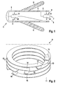
- FIG. 1 the region of the distal end 1 of an electrode device is shown, which has an elongate electrode body 2 made of a flexible, insulating tube.
- a tip contact pole 3 Attached to the tip of the electrode body 2 is a tip contact pole 3, commonly referred to as a tip electrode, which is brought into contact with cardiac tissue, for example, when the electrode device is used.
- a ring contact pole 4 is fixed at a distance in the electrode body 2, which is also electrocardiological for delivery Stimulation currents or for measuring electrocardiological signals is used.
- a plurality of silicone anchor 5 for attachment of the electrode device at a suitable location in cardiac tissue obliquely in the proximal direction.
- an electromedical implant not shown, such as a pacemaker
- the tip or ring contact pole 3, 4 is made in each case via an electrical supply line 6, 7, which are formed as a rule as a helix.
- a high-frequency filter 8 is turned on, which consists of an LC resonant circuit consisting of a parallel connection of a coil 9 and a capacitor 10.
- the electronic components realizing the coil 9 and the capacitor 10 are each designed as miniature components in LTCC technology, as has already been explained in detail at the beginning of the description. To avoid repetition can be referenced.
- the integration of the capacitor 10 can be done in a conventional SMD component with a small design. Sizes with the identifiers 0402, 0201 or 1005 are advantageous in this context.
- the capacitor 10 is integrated as a LTCC component in dielectric material.
- An alternative is to mount a LTCC capacitor 10 on a dielectric material by soldering, welding or gluing with conductive adhesive.
- the capacitor 10 When using a dielectric material as a ceramic dielectric, the capacitor 10 can be implemented as an intrinsic capacitor. Thus, the volume of the capacitor in the entire electronic assembly of the high-frequency filter 8 can be distributed, so shows, for example, the Fig. 5A the cross section through an LTCC capacitor.
- the comb-like structures 20 and 22 provide the metallization layers within the LTCC 21 substrate. Two adjacent metal layers each form a capacitor with the intervening ceramic substrate.
- Fig. 5B shown electrically interconnected to form a capacitor with a larger capacitance.
- the electrical connections 23 between the individual layers are usually implemented in the LTCC technique as an implementation.
- the following figure shows a possible embodiment in which the connections of the capacitor are led to the surface.
- the terminals can also be connected directly to the coil or coils within the substrate.
- a coil 9 in LTCC technology is clear.
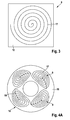
- Such a coil 9 is directly in a ceramic substrate 11 (dashed in FIG Fig. 2 represented) by the coil 9 is sandwiched from alternately stacked, open metal rings 12 and between - for the sake of clarity omitted - ceramic layers is constructed.
- the metal rings 12 are formed like an annular disk of flat material and arranged in the direction of overlapping overlapping parallel to each other.
- the gap 13 between the open ends 14 of the metal rings 12 extends over a few degrees of circumference of the metal rings 12.
- the gaps 13 of adjacent metal rings 12 are each offset in the peripheral direction so that they are out of overlap.
- the electrical connection between the individual metal rings 12 is made in each case via feedthroughs 15 in the form of short line pieces in front of the respective ends of the metal rings 12.
- Fig. 3 is highly schematically shown an alternative embodiment of the coil 9.
- This is formed as a planar coil on a flexible substrate 16 by the coil leads 17 are printed as a spiral on the substrate 16. Due to its flexibility, the substrate 16 can then be bent so that the entire coil 9 can be integrated to save space in the corresponding electronic component.
- the Fig. 4A and 4B Finally, the integration of four coils 9 in the form of each printed spirals on a flexible substrate 16.
- the four coils 9 are connected in series, wherein the connection between the inner end of the coil line 17 and the outer beginning of the next coil 9 by a straight Connecting line 19 can be made on the back of the flexible substrate 16.
- the four coils 9 are indicated on the substrate, the latter being wound into a coil cylinder 18.
Landscapes
- Health & Medical Sciences (AREA)
- Engineering & Computer Science (AREA)
- Radiology & Medical Imaging (AREA)
- Heart & Thoracic Surgery (AREA)
- Biomedical Technology (AREA)
- Nuclear Medicine, Radiotherapy & Molecular Imaging (AREA)
- Cardiology (AREA)
- Life Sciences & Earth Sciences (AREA)
- Animal Behavior & Ethology (AREA)
- General Health & Medical Sciences (AREA)
- Public Health (AREA)
- Veterinary Medicine (AREA)
- Power Engineering (AREA)
- Filters And Equalizers (AREA)
- Electrotherapy Devices (AREA)
Abstract
Description
- Die Erfindung betrifft eine Elektrodenvorrichtung für aktive medizinische Implantate, die einen langgestreckten Elektrodenkörper mit einem proximalen und einem distalen Ende, einen Spitzen-Kontaktpol am distalen Ende und/oder einen Ring-Kontaktpol vor dem distalen Ende, elektrische Zuleitungen zu dem Spitzen- bzw. Ring-Kontaktpol und einen aus einem oder mehreren elektronischen Bauelementen bestehenden Hochfrequenz-Filter in mindestens einer der Zuleitungen umfasst, der dem Spitzen- bzw. Ring-Kontaktpol zugeordnet ist.
- Zum Hintergrund der Erfindung ist festzuhalten, dass der Erfindungsgegenstand in erster Linie im Zusammenhang mit Herzschrittmachern, implantierbaren Defibrillatoren und anderen Typen von aktiven implantierbaren elektromedizinischen Geräten relevant ist. Letztere weisen in aller Regel mindestens eine strom-/spannungsführende Zuleitung in der Elektrodenvorrichtung - üblicherweise als kurz als "Elektrode" bezeichnet - auf, deren distales Ende beispielsweise in einer Herzkammer angeordnet und zur Messung kardiologischer Potentialsignale oder zur Abgabe entsprechender therapeutischer Stromsignale dient.
- Die Kompatibilität derartiger Elektrodenvorrichtungen bei implantierbaren elektromedizinischen Geräten mit hochfrequenten Magnetfeldern, wie sie insbesondere bei bildgebenden diagnostischen Verfahren auf Magnetresonanz-Basis - sogenannte MRI- (magnetic resonance imaging) Verfahren - verwendet werden, stellt ein gravierendes Problem dar. Bei solchen MRI-Verfahren wird einem starken statischen Magnetfeld ein mit Radiofrequenz (RF) gepulstes magnetisches Wechselfeld überlagert, das dazu dient, den Energiestatus der Protonen im untersuchten Gewebe zu verändern und entsprechende MRI-Signale aus dem Gewebe zu produzieren.
- Dieses magnetische Wechselfeld führt nach den Gesetzen der elektromagnetischen Induktion in den Zuleitung der hier in Rede stehenden Elektrodenvorrichtungen von elektromedizinischen Geräteimplantaten zu Wechselspannungen, deren Energie insbesondere an den elektrisch leitenden Kontaktpolen der Elektrodenvorrichtung zum menschlichen Gewebe in Wärme umgesetzt wird. Dies kann zu einer erheblichen Erhitzung beispielsweise des Spitzenkontaktes einer Herzelektrode mit einer entsprechenden Beeinträchtigung und sogar Schädigung des damit in Berührung stehenden oder umliegenden Herzgewebes führen.
- Um diese Problematik zu vermeiden, schlägt die
US 7,363,090 B2 die Verwendung von Filtern auf der Basis von Schwingkreisen aus parallel geschalteter Spule und Kondensator vor, die der entsprechenden Zuleitung für den Spitzen-Kontaktpol oder einen Ring-Kontaktpol einer entsprechenden Elektrode eines implantierbaren elektromedizinischen Gerätes zugeordnet ist. Die in diesem vorbekannten Patent offenbarten Filter sind in der Praxisumsetzung der Patentinhaberin als vergleichsweise voluminöse, die Elektrodenvorrichtung auf einer gewissen Länge versteifende Komponenten ausgebildet, die der damit ausgerüsteten Elektrode ungünstige mechanische Eigenschaften verleihen. Ferner ist der Filter in einem in sich geschlossenen Gehäuse untergebracht, das keine Durchführung für die in aller Regel beim Implantieren einer Elektrode verwendeten Führungsdrähte bereit stellt. Insoweit sind die Einsatzmöglichkeiten dieser bekannten Elektrode mit Filtereinrichtung begrenzt. - Aus der
US 2009/0281592 A1 sind Filterkomponenten zur Herabsetzung der Erhitzung von Schrittmacher-Elektroden eines elektromedizinischen Implantats bei der Einwirkung hochfrequenter Magnetfelder in Folge von MRI-Prozeduren bekannt, wobei eine Induktionsspule um einen nicht-leitenden, zentralen Abschnitt eines Schaftes aufgebracht ist, der einen Spitzen-Kontaktpol mit einem inneren Wendelleiter der Elektrodenvorrichtung verbindet. Durch die Montage einer Induktionsspule auf dem Schaft wird eine induktive Signalfilterung zur Herabsetzung der Elektrodenspitze ohne die Notwendigkeit eines vergleichsweise langen, voluminösen Spulenkörpers entlang der Länge der Elektrode erreicht. Kapazitive Elemente können ebenfalls in den Schaft integriert werden, um einen LC-Filterkreis zu schaffen. Alternativ dazu ist in dieser Druckschrift eine sogenannte "Luftspule" als induktives Element offenbart, bei der der Schaft weggelassen werden kann. - Die Filtereinrichtungen nach dem Stand der Technik führen in der Regel zu einer übermäßigen Versteifung der Elektrodenvorrichtung auf einer bestimmten Länge. Sie sind vergleichsweise aufwendig und wenig kompakt ausgebildet.
- Davon ausgehend liegt der Erfindung die Aufgabe zugrunde, Elektrodenvorrichtungen für aktive medizinische Implantate so zu verbessern, dass ihre Filtereinrichtungen möglichst weitgehend miniaturisiert sind. Diese Aufgabe wird durch die im Kennzeichnungsteil des Patentanspruchs 1 angegebenen Merkmale gelöst, wonach das oder die elektronischen Bauelemente jeweils als Miniatur-Bauelement in LTCC-Technik ausgeführt ist.
- Solche LTCC-Bauelemente sind aus Niedertemperatur-Einbrand-Keramiken (Low Temperature Cofired Ceramics) hergestellt und beruhen auf einer Technologie zur Herstellung von Mehrlagenschaltungen auf der Basis von gesinterten Keramikträgern. Damit können grundsätzlich Leiterbahnen, Kondensatoren, Widerstände und Spulen erzeugt werden, die durch Siebdruck oder fotochemische Prozesse aufgebracht sind. Die ungebrannten Keramikfolien werden einzeln strukturiert, danach gestapelt und laminiert. Abschließend wird ein definiertes Sinterprofil mit einer Spitzentemperatur von ca. 850 bis 900°C gefahren.
- Diese Technologie vereint die Vorteile der Hochtemperatur-Einbrand-Keramik-Technik und der Dickschichttechnologie. Sie ist vor allem bei kleinen und mittleren Stückzahlen eine kostengünstige Alternative zur herkömmlichen Leiterplattentechnologie, was sich günstig im Bereich der Medizintechnik auswirkt.
- Mithilfe solcher LTCC-Bauelemente kann ein hoher Integrationsgrad der damit hergestellten Hochfrequenz-Filter erzielt werden, was sich äußerst günstig im Hinblick auf deren geringes Bauvolumen auswirkt. Durch die kleinbauenden Hochfrequenz-Filter führen diese dann zu einer geringeren Versteifung der Elektrodenvorrichtung im Vergleich zur herkömmlichen Realisierung dieser Filtereinrichtungen.
- Gemäß einer bevorzugten Ausfiihrungsform kann der Hochfrequenz-Filter einen Kondensator und/oder eine Spule in LTCC-Technik aufweisen, wobei ein Kondensator als LTCC-Bauteil in ein dielektrisches Material integriert sein kann. Eine Montage eines Kondensators als LTCC-Bauteil auf einem dielektrischen Material durch Löten, Schweißen oder Kleben mit leitfähigem Klebstoff ist ebenfalls möglich.
- Sofern als dielektrisches Material ein keramisches Dielektrikum vorgesehen ist, kann damit ein intrinsischer Kondensator (z.B. das Sandwich leitenden Werkstoff, nichtleitenden (besonders dielektrisch ausgeprägter) Werkstoff, leitender Werkstoff bilden in Flussrichtung dieser Aufzählung einen Kondensator) implementiert werden.
- Eine bevorzugte Ausführungsform einer Spule in LTCC-Technik verwendet einen direkt in ein keramisches Substrat integrierten Aufbau. Dies kann vorzugsweise durch eine sandwichartige Schichtung aus wechselweise übereinander gelegten offenen Metallringen und Keramiklagen erfolgen, wobei benachbarte Metallringe an ihren offenen Enden über Durchführungen elektrisch verbunden sind. Damit lassen sich kompakte Spulen mit ausreichenden Induktivitätswerten realisieren.
- Auch eine Ausbildung der Spule als planare Spule auf einem flexiblen Substrat ist möglich. Dies hat den Vorteil, dass das Bauelement dann aufgrund der Flexibilität des Substrats gebogen und platzsparend in der elektronischen Baugruppe des Hochfrequenz-Filters untergebracht werden kann. Eine besonders kompakte Ausführungsform unter Verwendung eines flexiblen Substrats stellt die Ausbildung der Spule als Spirale dar, da die Leiterbahnen dann in einer Ebene liegen. Dieses Konzept kann auch in Form mehrerer Spiralen auf einem flexiblen Substrat umgesetzt werden. Letzteres kann dann vorzugsweise zu einem Zylinder gewickelt werden, sodass sich eine optimal an den Einbau in einer Elektrodenvorrichtung angepasste Konfiguration ergibt.
- Weitere Merkmale, Einzelheiten und Vorteile der Erfindung ergeben sich aus der nachfolgenden Beschreibung, in der Ausführungsbeispiele der Erfindung näher erläutert sind. Es zeigen:
- Fig. 1
- einen schematischen Längsschnitt einer Elektrodenvorrichtung in ihrem distalen Endbereich,
- Fig. 2
- eine perspektivische Ansicht der Leiterbahnen einer LTCC-Spule,
- Fig. 3
- eine Draufsicht auf eine als Spirale ausgebildete LTCC-Spule,
- Fig. 4A
- eine Darstellung eines Spulenzylinders mit vier spiralig aufgebauten Spulen,
- Fig. 4B
- eine Darstellung eines Spulenzylinders mit vier spiralig aufgebauten Spulen,
- Fig. 5A
- eine Darstellung eines Querschnitts durch einen LTCC Kondensators, und
- Fig. 5B
- eine Darstellung eines Querschnitts durch einen LTCC Kondensators, der mit Durchführungen verbunden ist.
- In der
Fig. 1 ist der Bereich des distalen Endes 1 einer Elektrodenvorrichtung dargestellt, die einen langgestreckten Elektrodenkörper 2 aus einem flexiblen, isolierenden Schlauch aufweist. - An der Spitze des Elektrodenkörpers 2 ist ein üblicherweise als Tip-Elektrode bezeichneter Spitzen-Kontaktpol 3 befestigt, der beim Einsatz der Elektrodenvorrichtung in Kontakt beispielsweise mit Herzgewebe gebracht wird.
- In proximaler Richtung vor dem Spitzen-Kontaktpol 3 ist mit Abstand dazu ein Ring-Kontaktpol 4 im Elektrodenkörper 2 befestigt, der ebenfalls zur Abgabe elektrokardiologischer Reizströme oder zur Messung elektrokardiologischer Signale dient. Zwischen Spitzen- und Ring-Kontaktpol 3, 4 stehen vom Elektrodenkörper 2 mehrere Silikon-Anker 5 zur Befestigung der Elektrodenvorrichtung an geeigneter Stelle in Herzgewebe schräg in proximaler Richtung ab.
- Die elektrische Verbindung zwischen einem nicht näher dargestellten elektromedizinischen Implantat, wie beispielsweise einem Herzschrittmacher, und dem Spitzen- bzw. Ring-Kontaktpol 3, 4 wird jeweils über eine elektrische Zuleitung 6, 7 vorgenommen, die in aller Regel als Wendel ausgebildet sind.
- Wie schematisch nach Art eines Blockschaltbildes in
Fig. 1 angedeutet ist, sind in den beiden Zuleitungen 6, 7 jeweils ein Hochfrequenz-Filter 8 eingeschaltet, die aus einem LC-Schwingkreis bestehend aus einer Parallelschaltung einer Spule 9 und eines Kondensators 10 besteht. - Die die Spule 9 und den Kondensator 10 realisierenden elektronischen Bauelemente sind jeweils als Miniatur-Bauelemente in LTCC-Technik ausgelegt, wie sie bereits eingangs der Beschreibung ausführlich dargelegt wurde. Zur Vermeidung von Wiederholungen kann darauf verwiesen werden.
- Die Integration des Kondensators 10 kann in ein herkömmliches SMD-Bauteil mit einer kleinen Bauform erfolgen. Baugrößen mit den Kennungen 0402, 0201 oder 1005 sind in diesem Zusammenhang vorteilhaft. Der Kondensator 10 ist dabei als LTCC-Bauteil in dielektrisches Material integriert. Eine Alternative ist die Montage eines LTCC-Kondensators 10 auf ein dielektrisches Material durch Löten, Schweißen oder Kleben mit leitfähigem Klebstoff.
- Bei der Nutzung eines dielektrischen Materials als keramisches Dielektrikum kann der Kondensator 10 als intrinsischer Kondensator implementiert werden. Damit kann das Volumen des Kondensators in der gesamten elektronischen Baugruppe des Hochfrequenz-Filters 8 verteilt werden, so zeigt beispielsweise die
Fig. 5A den Querschnitt durch einen LTCC Kondensator. Die kammartigen Strukturen 20 und 22 stellen die Metallisierungsschichten innerhalb des LTCC 21 Substrates dar. Zwei benachbarte Metallschichten bilden mit dem dazwischen liegenden Keramiksubstrat je einen Kondensator. - Diese Einzelkondensatoren können, wie in
Fig. 5B gezeigt, elektrisch so verschaltet werden, dass sie einen Kondensator mit größerer Kapazizät bilden. Die elektrischen Verbindungen 23 zwischen den einzelnen Schichten werden in der LTCC Technik üblicherweise als Durchführung umgesetzt. Folgende Abbildung zeigt eine mögliche Ausführungsform, bei der die Anschlüsse des Kondensators auf die Oberfläche geführt sind. - Im speziellen Anwendungsfall des Kondensators als Teil eines Filter können die Anschlüsse auch direkt mit der oder den Spulen innerhalb des Substrates verbunden werden.
- Aus
Fig. 2 wird der Aufbau einer Spule 9 in LTCC-Technik deutlich. Eine solche Spule 9 ist direkt in ein keramisches Substrat 11 (gestrichelt inFig. 2 dargestellt) integriert, indem die Spule 9 sandwichartig aus wechselweise übereinander geschichteten, offenen Metallringen 12 und dazwischen - der Übersichtlichkeit halber weggelassenen - Keramiklagen aufgebaut ist. Die Metallringe 12 sind ringscheibenartig aus Flachmaterial gebildet und in Schichtungsrichtung überlappend parallel zueinander angeordnet. Der Spalt 13 zwischen den offenen Enden 14 der Metallringe 12 erstreckt sich über wenige Umfangsgrade der Metallringe 12. Die Spalte 13 von benachbarten Metallringen 12 sind jeweils in peripherer Richtung so zueinander versetzt, dass sie sich außer Überdeckung befinden. - Die elektrische Verbindung zwischen den einzelnen Metallringen 12 wird jeweils über Durchführungen 15 in Form von kurzen Leitungsstücken vor den jeweiligen Enden der Metallringe 12 hergestellt.
- In
Fig. 3 ist höchst schematisch eine alternative Ausführungsform der Spule 9 dargestellt. Diese ist als planare Spule auf einem flexiblen Substrat 16 ausgebildet, indem die Spulenleitungen 17 als Spirale auf das Substrat 16 gedruckt sind. Aufgrund seiner Flexibilität kann das Substrat 16 dann gebogen werden, sodass die gesamte Spule 9 platzsparend im entsprechenden elektronischen Bauelement integriert werden kann. - Die
Fig. 4A und4B schließlich zeigen die Integration von vier Spulen 9 in Form jeweils aufgedruckter Spiralen auf einem flexiblen Substrat 16. Die vier Spulen 9 sind dabei seriell verschaltet, wobei die Verbindung zwischen dem inneren Ende der Spulenleitung 17 und dem äußeren Anfang der jeweils nächsten Spule 9 durch eine gerade Verbindungsleitung 19 auf der Rückseite des flexiblen Substrates 16 erfolgen kann. In derFig. 4 sind die vier Spulen 9 auf dem Substrat angedeutet, wobei Letzteres zu einem Spulenzylinder 18 gewickelt ist. -
- 1
- Distales Ende
- 2
- Elektrodenkörper
- 3
- Spitzen-Kontaktpol
- 4
- Ring-Kontaktpol
- 5
- Silikon-Anker
- 6
- Zuleitung
- 7
- Zuleitung
- 8
- Hochfrequenz-Filter
- 9
- Spule
- 10
- Kondensator
- 11
- Substrat
- 12
- Metallringe
- 13
- Spalt
- 14
- Offenes Ende
- 15
- Durchführung
- 16
- Flexibles Substrat
- 17
- Spulenleitung
- 18
- Spulenzylinder
- 19
- Verbindungsleitung
- 20
- Metallisierungsschichten im LTCC
- 21
- LTCC Substrat
- 22
- Metallisierungsschichten im LTCC
- 23
- Elektrische Verbindung
Claims (11)
- Elektrodenvorrichtung für aktive medizinische Implantate umfassend einen langgestreckten Elektrodenkörper (2) mit einem proximalen und einem distalen Ende (1),
einen Spitzen-Kontaktpol (3) am distalen Ende (1) und/oder einen Ring-Kontaktpol (4) vor dem distalen Ende (1),
elektrische Zuleitungen (6, 7) zu dem Spitzen- bzw. Ring-Kontaktpol (3, 4), und einen aus einem oder mehreren elektronischen Bauelementen (9, 10) bestehenden Hochfrequenz-Filter (8) in mindestens einer der Zuleitungen (6, 7), der dem Spitzen- bzw. Ring-Kontaktpol (3, 4) zugeordnet ist,
dadurch gekennzeichnet, dass
das oder die elektronischen Bauelemente (9, 10) jeweils als Miniatur-Bauelement in LTCC-Technik ausgeführt ist. - Elektrodenvorrichtung nach Anspruch 1, dadurch gekennzeichnet, dass der Hochfrequenz-Filter (8) einen Kondensator (10) und/oder eine Spule (9) in LTCC-Technik aufweist.
- Elektrodenvorrichtung nach Anspruch 1 oder 2, dadurch gekennzeichnet, dass ein Kondensator (10) als LTCC-Bauteil in dielektrisches Material integriert ist.
- Elektrodenvorrichtung nach Anspruch 1 oder 2, dadurch gekennzeichnet, dass ein Kondensator (10) als LTCC-Bauteil auf einem dielektrischen Material durch Löten, Schweißen oder Kleben mit leitfähigen Klebstoff montiert ist.
- Elektrodenvorrichtung nach Anspruch 4, dadurch gekennzeichnet, dass als dielektrisches Material ein keramisches Dielektrikum zur Implementierung des Kondensator als intrinsischer Kondensator vorgesehen ist.
- Elektrodenvorrichtung nach Anspruch 1 oder 2, dadurch gekennzeichnet, dass die Spule (9) direkt in einem keramischen Substrat (11) integriert aufgebaut ist.
- Elektrodenvorrichtung nach Anspruch 6, dadurch gekennzeichnet, dass die Spule (9) sandwichartig aus wechselweise übereinander geschichteten offenen Metallringen (12) und Keramiklagen aufgebaut ist, wobei benachbarte Metallringe (12) an ihren offenen Enden (14) über Durchführungen (15) elektrisch verbunden sind.
- Elektrodenvorrichtung nach Anspruch 1 oder 2, dadurch gekennzeichnet, dass die Spule (9) als planare Spule auf einem flexiblen Substrat (16) ausgebildet ist.
- Elektrodenvorrichtung nach Anspruch 8, dadurch gekennzeichnet, dass die Spule (9) als Spirale auf dem flexiblen Substrat (16) ausgebildet ist.
- Elektrodenvorrichtung nach Anspruch 9, dadurch gekennzeichnet, dass mehrere Spiralen auf einem flexiblen Substrat (16) aufgebracht sind.
- Elektrodenvorrichtung nach Anspruch 10, dadurch gekennzeichnet, dass das Substrat (16) zu einem Zylinder (18) gewickelt ist.
Applications Claiming Priority (1)
| Application Number | Priority Date | Filing Date | Title |
|---|---|---|---|
| DE102010000372 | 2010-02-11 |
Publications (2)
| Publication Number | Publication Date |
|---|---|
| EP2359899A1 true EP2359899A1 (de) | 2011-08-24 |
| EP2359899B1 EP2359899B1 (de) | 2015-06-17 |
Family
ID=43885391
Family Applications (1)
| Application Number | Title | Priority Date | Filing Date |
|---|---|---|---|
| EP11153008.5A Not-in-force EP2359899B1 (de) | 2010-02-11 | 2011-02-02 | Elektrodenvorrichtung für aktive medizinische Implantate |
Country Status (2)
| Country | Link |
|---|---|
| US (1) | US8527065B2 (de) |
| EP (1) | EP2359899B1 (de) |
Families Citing this family (4)
| Publication number | Priority date | Publication date | Assignee | Title |
|---|---|---|---|---|
| US9468750B2 (en) | 2006-11-09 | 2016-10-18 | Greatbatch Ltd. | Multilayer planar spiral inductor filter for medical therapeutic or diagnostic applications |
| EP2719421A1 (de) * | 2012-07-02 | 2014-04-16 | BIOTRONIK SE & Co. KG | Implantierbare medizinische Schlauchanordnung |
| EP3269419A1 (de) * | 2013-08-04 | 2018-01-17 | Greatbatch Ltd. | Mehrschichtiger planarer spiralinduktorfilter für medizinische, therapeutische oder diagnostische anwendungen |
| EP3957243A1 (de) | 2019-06-21 | 2022-02-23 | UNIST (Ulsan National Institute of Science and Technology) | Antennenvorrichtung zur messung biometrischer informationen mittels magnetischer dipolresonanz |
Citations (6)
| Publication number | Priority date | Publication date | Assignee | Title |
|---|---|---|---|---|
| US6567703B1 (en) * | 2000-11-08 | 2003-05-20 | Medtronic, Inc. | Implantable medical device incorporating miniaturized circuit module |
| US20040176817A1 (en) * | 2002-12-09 | 2004-09-09 | Medtronic, Inc. | Modular implantable medical device |
| US20070217121A1 (en) * | 2006-03-14 | 2007-09-20 | Greatbatch Ltd. | Integrated Filter Feedthrough Assemblies Made From Low Temperature Co-Fired (LTCC) Tape |
| US7363090B2 (en) | 2001-04-13 | 2008-04-22 | Greatbatch Ltd. | Band stop filter employing a capacitor and an inductor tank circuit to enhance MRI compatibility of active implantable medical devices |
| US20090243756A1 (en) * | 2008-03-20 | 2009-10-01 | Greatbatch Ltd. | Shielded three-terminal flat-through emi/energy dissipating filter |
| US20090281592A1 (en) | 2008-05-08 | 2009-11-12 | Pacesetter, Inc. | Shaft-mounted rf filtering elements for implantable medical device lead to reduce lead heating during mri |
-
2011
- 2011-01-31 US US13/018,198 patent/US8527065B2/en not_active Expired - Fee Related
- 2011-02-02 EP EP11153008.5A patent/EP2359899B1/de not_active Not-in-force
Patent Citations (6)
| Publication number | Priority date | Publication date | Assignee | Title |
|---|---|---|---|---|
| US6567703B1 (en) * | 2000-11-08 | 2003-05-20 | Medtronic, Inc. | Implantable medical device incorporating miniaturized circuit module |
| US7363090B2 (en) | 2001-04-13 | 2008-04-22 | Greatbatch Ltd. | Band stop filter employing a capacitor and an inductor tank circuit to enhance MRI compatibility of active implantable medical devices |
| US20040176817A1 (en) * | 2002-12-09 | 2004-09-09 | Medtronic, Inc. | Modular implantable medical device |
| US20070217121A1 (en) * | 2006-03-14 | 2007-09-20 | Greatbatch Ltd. | Integrated Filter Feedthrough Assemblies Made From Low Temperature Co-Fired (LTCC) Tape |
| US20090243756A1 (en) * | 2008-03-20 | 2009-10-01 | Greatbatch Ltd. | Shielded three-terminal flat-through emi/energy dissipating filter |
| US20090281592A1 (en) | 2008-05-08 | 2009-11-12 | Pacesetter, Inc. | Shaft-mounted rf filtering elements for implantable medical device lead to reduce lead heating during mri |
Also Published As
| Publication number | Publication date |
|---|---|
| EP2359899B1 (de) | 2015-06-17 |
| US20110196462A1 (en) | 2011-08-11 |
| US8527065B2 (en) | 2013-09-03 |
Similar Documents
| Publication | Publication Date | Title |
|---|---|---|
| EP1923094B1 (de) | Elektrodenkatheter zu Interventionszwecken | |
| US9061139B2 (en) | Implantable lead with a band stop filter having a capacitor in parallel with an inductor embedded in a dielectric body | |
| EP2359896B1 (de) | Elektrodenvorrichtung zur Strom- oder Spannungsführung zwischen einem implantierbaren elektromedizinischen Gerät und einem Therapie- und/oder Diagnoseort im menschlichen Körper | |
| US7702387B2 (en) | Tank filters adaptable for placement with a guide wire, in series with the lead wires or circuits of active medical devices to enhance MRI compatibility | |
| EP1945297B1 (de) | Nutschen in reihenweiser anordnung mit den führungsdrähten oder kreisläufen aktiver medizinischer vorrichtung für erhöhte mri-kompatibilität | |
| US7853324B2 (en) | Tank filters utilizing very low K materials, in series with lead wires or circuits of active medical devices to enhance MRI compatibility | |
| US8116862B2 (en) | Tank filters placed in series with the lead wires or circuits of active medical devices to enhance MRI compatibility | |
| US20110208030A1 (en) | Tank filters placed in series with the lead wires or circuits of active medical devices to enhance mri compatability | |
| US7804676B2 (en) | Hybrid discoidal/tubular capacitor | |
| EP2269200A2 (de) | Abgeschirmtes flachdurchgangs-emi/energieableitungsfilter mit drei anschlüssen | |
| EP2359899B1 (de) | Elektrodenvorrichtung für aktive medizinische Implantate | |
| EP2359895B1 (de) | Adaptionssonde zur Einführung in implantierte Elektrodenvorrichtungen aktiver medizinischer Implantate sowie Set bestehend aus einer implantierbaren Elektrodenvorrichtung und einer Adaptionssonde | |
| DE102020100121A1 (de) | Implantierbare Elektrode mit einer Stichleitung | |
| EP2465572A2 (de) | MRT-kompatible implantierbare Leitung | |
| EP2359894A1 (de) | Elektrode mit HF-Filter für aktive medizinische Implantate | |
| EP2875844B1 (de) | Implantierbare Elektrodeneinrichtung, insbesondere für kardiologische Geräte, wie Herzschrittmacher | |
| EP2848282B1 (de) | Implantierbares Gerät | |
| EP2985054B1 (de) | Implantierbares gerät mit elektrischem filter | |
| DE102019107600B4 (de) | Antennenanordnung | |
| US12551697B2 (en) | Circuit for a lead of an implantable medical device |
Legal Events
| Date | Code | Title | Description |
|---|---|---|---|
| PUAI | Public reference made under article 153(3) epc to a published international application that has entered the european phase |
Free format text: ORIGINAL CODE: 0009012 |
|
| PUAI | Public reference made under article 153(3) epc to a published international application that has entered the european phase |
Free format text: ORIGINAL CODE: 0009012 |
|
| AK | Designated contracting states |
Kind code of ref document: A1 Designated state(s): AL AT BE BG CH CY CZ DE DK EE ES FI FR GB GR HR HU IE IS IT LI LT LU LV MC MK MT NL NO PL PT RO RS SE SI SK SM TR |
|
| AX | Request for extension of the european patent |
Extension state: BA ME |
|
| 17P | Request for examination filed |
Effective date: 20120210 |
|
| RIC1 | Information provided on ipc code assigned before grant |
Ipc: A61N 1/08 20060101ALI20150203BHEP Ipc: A61N 1/05 20060101ALI20150203BHEP Ipc: G01R 33/28 20060101ALI20150203BHEP Ipc: A61N 1/375 20060101AFI20150203BHEP Ipc: H03H 1/00 20060101ALI20150203BHEP Ipc: H03H 7/01 20060101ALI20150203BHEP |
|
| GRAP | Despatch of communication of intention to grant a patent |
Free format text: ORIGINAL CODE: EPIDOSNIGR1 |
|
| INTG | Intention to grant announced |
Effective date: 20150324 |
|
| GRAS | Grant fee paid |
Free format text: ORIGINAL CODE: EPIDOSNIGR3 |
|
| GRAA | (expected) grant |
Free format text: ORIGINAL CODE: 0009210 |
|
| AK | Designated contracting states |
Kind code of ref document: B1 Designated state(s): AL AT BE BG CH CY CZ DE DK EE ES FI FR GB GR HR HU IE IS IT LI LT LU LV MC MK MT NL NO PL PT RO RS SE SI SK SM TR |
|
| REG | Reference to a national code |
Ref country code: GB Ref legal event code: FG4D Free format text: NOT ENGLISH |
|
| REG | Reference to a national code |
Ref country code: CH Ref legal event code: EP |
|
| REG | Reference to a national code |
Ref country code: AT Ref legal event code: REF Ref document number: 731568 Country of ref document: AT Kind code of ref document: T Effective date: 20150715 |
|
| REG | Reference to a national code |
Ref country code: IE Ref legal event code: FG4D Free format text: LANGUAGE OF EP DOCUMENT: GERMAN |
|
| REG | Reference to a national code |
Ref country code: DE Ref legal event code: R096 Ref document number: 502011007080 Country of ref document: DE |
|
| REG | Reference to a national code |
Ref country code: DE Ref legal event code: R082 Ref document number: 502011007080 Country of ref document: DE |
|
| PG25 | Lapsed in a contracting state [announced via postgrant information from national office to epo] |
Ref country code: NO Free format text: LAPSE BECAUSE OF FAILURE TO SUBMIT A TRANSLATION OF THE DESCRIPTION OR TO PAY THE FEE WITHIN THE PRESCRIBED TIME-LIMIT Effective date: 20150917 Ref country code: LT Free format text: LAPSE BECAUSE OF FAILURE TO SUBMIT A TRANSLATION OF THE DESCRIPTION OR TO PAY THE FEE WITHIN THE PRESCRIBED TIME-LIMIT Effective date: 20150617 Ref country code: HR Free format text: LAPSE BECAUSE OF FAILURE TO SUBMIT A TRANSLATION OF THE DESCRIPTION OR TO PAY THE FEE WITHIN THE PRESCRIBED TIME-LIMIT Effective date: 20150617 Ref country code: FI Free format text: LAPSE BECAUSE OF FAILURE TO SUBMIT A TRANSLATION OF THE DESCRIPTION OR TO PAY THE FEE WITHIN THE PRESCRIBED TIME-LIMIT Effective date: 20150617 |
|
| REG | Reference to a national code |
Ref country code: LT Ref legal event code: MG4D Ref country code: NL Ref legal event code: MP Effective date: 20150617 |
|
| PG25 | Lapsed in a contracting state [announced via postgrant information from national office to epo] |
Ref country code: RS Free format text: LAPSE BECAUSE OF FAILURE TO SUBMIT A TRANSLATION OF THE DESCRIPTION OR TO PAY THE FEE WITHIN THE PRESCRIBED TIME-LIMIT Effective date: 20150617 Ref country code: BG Free format text: LAPSE BECAUSE OF FAILURE TO SUBMIT A TRANSLATION OF THE DESCRIPTION OR TO PAY THE FEE WITHIN THE PRESCRIBED TIME-LIMIT Effective date: 20150917 Ref country code: LV Free format text: LAPSE BECAUSE OF FAILURE TO SUBMIT A TRANSLATION OF THE DESCRIPTION OR TO PAY THE FEE WITHIN THE PRESCRIBED TIME-LIMIT Effective date: 20150617 Ref country code: GR Free format text: LAPSE BECAUSE OF FAILURE TO SUBMIT A TRANSLATION OF THE DESCRIPTION OR TO PAY THE FEE WITHIN THE PRESCRIBED TIME-LIMIT Effective date: 20150918 |
|
| PG25 | Lapsed in a contracting state [announced via postgrant information from national office to epo] |
Ref country code: EE Free format text: LAPSE BECAUSE OF FAILURE TO SUBMIT A TRANSLATION OF THE DESCRIPTION OR TO PAY THE FEE WITHIN THE PRESCRIBED TIME-LIMIT Effective date: 20150617 |
|
| PG25 | Lapsed in a contracting state [announced via postgrant information from national office to epo] |
Ref country code: SK Free format text: LAPSE BECAUSE OF FAILURE TO SUBMIT A TRANSLATION OF THE DESCRIPTION OR TO PAY THE FEE WITHIN THE PRESCRIBED TIME-LIMIT Effective date: 20150617 Ref country code: RO Free format text: LAPSE BECAUSE OF NON-PAYMENT OF DUE FEES Effective date: 20150617 Ref country code: CZ Free format text: LAPSE BECAUSE OF FAILURE TO SUBMIT A TRANSLATION OF THE DESCRIPTION OR TO PAY THE FEE WITHIN THE PRESCRIBED TIME-LIMIT Effective date: 20150617 Ref country code: PT Free format text: LAPSE BECAUSE OF FAILURE TO SUBMIT A TRANSLATION OF THE DESCRIPTION OR TO PAY THE FEE WITHIN THE PRESCRIBED TIME-LIMIT Effective date: 20151019 Ref country code: IS Free format text: LAPSE BECAUSE OF FAILURE TO SUBMIT A TRANSLATION OF THE DESCRIPTION OR TO PAY THE FEE WITHIN THE PRESCRIBED TIME-LIMIT Effective date: 20151017 Ref country code: PL Free format text: LAPSE BECAUSE OF FAILURE TO SUBMIT A TRANSLATION OF THE DESCRIPTION OR TO PAY THE FEE WITHIN THE PRESCRIBED TIME-LIMIT Effective date: 20150617 Ref country code: ES Free format text: LAPSE BECAUSE OF FAILURE TO SUBMIT A TRANSLATION OF THE DESCRIPTION OR TO PAY THE FEE WITHIN THE PRESCRIBED TIME-LIMIT Effective date: 20150617 |
|
| REG | Reference to a national code |
Ref country code: DE Ref legal event code: R097 Ref document number: 502011007080 Country of ref document: DE |
|
| PLBE | No opposition filed within time limit |
Free format text: ORIGINAL CODE: 0009261 |
|
| STAA | Information on the status of an ep patent application or granted ep patent |
Free format text: STATUS: NO OPPOSITION FILED WITHIN TIME LIMIT |
|
| PG25 | Lapsed in a contracting state [announced via postgrant information from national office to epo] |
Ref country code: IT Free format text: LAPSE BECAUSE OF FAILURE TO SUBMIT A TRANSLATION OF THE DESCRIPTION OR TO PAY THE FEE WITHIN THE PRESCRIBED TIME-LIMIT Effective date: 20150617 Ref country code: DK Free format text: LAPSE BECAUSE OF FAILURE TO SUBMIT A TRANSLATION OF THE DESCRIPTION OR TO PAY THE FEE WITHIN THE PRESCRIBED TIME-LIMIT Effective date: 20150617 |
|
| 26N | No opposition filed |
Effective date: 20160318 |
|
| PG25 | Lapsed in a contracting state [announced via postgrant information from national office to epo] |
Ref country code: BE Free format text: LAPSE BECAUSE OF NON-PAYMENT OF DUE FEES Effective date: 20160229 |
|
| PG25 | Lapsed in a contracting state [announced via postgrant information from national office to epo] |
Ref country code: SI Free format text: LAPSE BECAUSE OF FAILURE TO SUBMIT A TRANSLATION OF THE DESCRIPTION OR TO PAY THE FEE WITHIN THE PRESCRIBED TIME-LIMIT Effective date: 20150617 |
|
| PG25 | Lapsed in a contracting state [announced via postgrant information from national office to epo] |
Ref country code: MC Free format text: LAPSE BECAUSE OF FAILURE TO SUBMIT A TRANSLATION OF THE DESCRIPTION OR TO PAY THE FEE WITHIN THE PRESCRIBED TIME-LIMIT Effective date: 20150617 Ref country code: LU Free format text: LAPSE BECAUSE OF FAILURE TO SUBMIT A TRANSLATION OF THE DESCRIPTION OR TO PAY THE FEE WITHIN THE PRESCRIBED TIME-LIMIT Effective date: 20160202 |
|
| GBPC | Gb: european patent ceased through non-payment of renewal fee |
Effective date: 20160202 |
|
| REG | Reference to a national code |
Ref country code: FR Ref legal event code: ST Effective date: 20161028 |
|
| PG25 | Lapsed in a contracting state [announced via postgrant information from national office to epo] |
Ref country code: GB Free format text: LAPSE BECAUSE OF NON-PAYMENT OF DUE FEES Effective date: 20160202 Ref country code: FR Free format text: LAPSE BECAUSE OF NON-PAYMENT OF DUE FEES Effective date: 20160229 |
|
| REG | Reference to a national code |
Ref country code: AT Ref legal event code: MM01 Ref document number: 731568 Country of ref document: AT Kind code of ref document: T Effective date: 20160202 |
|
| PG25 | Lapsed in a contracting state [announced via postgrant information from national office to epo] |
Ref country code: AT Free format text: LAPSE BECAUSE OF NON-PAYMENT OF DUE FEES Effective date: 20160202 |
|
| PG25 | Lapsed in a contracting state [announced via postgrant information from national office to epo] |
Ref country code: SE Free format text: LAPSE BECAUSE OF FAILURE TO SUBMIT A TRANSLATION OF THE DESCRIPTION OR TO PAY THE FEE WITHIN THE PRESCRIBED TIME-LIMIT Effective date: 20150617 Ref country code: NL Free format text: LAPSE BECAUSE OF FAILURE TO SUBMIT A TRANSLATION OF THE DESCRIPTION OR TO PAY THE FEE WITHIN THE PRESCRIBED TIME-LIMIT Effective date: 20150617 |
|
| PG25 | Lapsed in a contracting state [announced via postgrant information from national office to epo] |
Ref country code: MT Free format text: LAPSE BECAUSE OF FAILURE TO SUBMIT A TRANSLATION OF THE DESCRIPTION OR TO PAY THE FEE WITHIN THE PRESCRIBED TIME-LIMIT Effective date: 20150617 |
|
| PG25 | Lapsed in a contracting state [announced via postgrant information from national office to epo] |
Ref country code: HU Free format text: LAPSE BECAUSE OF FAILURE TO SUBMIT A TRANSLATION OF THE DESCRIPTION OR TO PAY THE FEE WITHIN THE PRESCRIBED TIME-LIMIT; INVALID AB INITIO Effective date: 20110202 Ref country code: SM Free format text: LAPSE BECAUSE OF FAILURE TO SUBMIT A TRANSLATION OF THE DESCRIPTION OR TO PAY THE FEE WITHIN THE PRESCRIBED TIME-LIMIT Effective date: 20150617 Ref country code: CY Free format text: LAPSE BECAUSE OF FAILURE TO SUBMIT A TRANSLATION OF THE DESCRIPTION OR TO PAY THE FEE WITHIN THE PRESCRIBED TIME-LIMIT Effective date: 20150617 |
|
| PG25 | Lapsed in a contracting state [announced via postgrant information from national office to epo] |
Ref country code: MK Free format text: LAPSE BECAUSE OF FAILURE TO SUBMIT A TRANSLATION OF THE DESCRIPTION OR TO PAY THE FEE WITHIN THE PRESCRIBED TIME-LIMIT Effective date: 20150617 Ref country code: TR Free format text: LAPSE BECAUSE OF FAILURE TO SUBMIT A TRANSLATION OF THE DESCRIPTION OR TO PAY THE FEE WITHIN THE PRESCRIBED TIME-LIMIT Effective date: 20150617 |
|
| PG25 | Lapsed in a contracting state [announced via postgrant information from national office to epo] |
Ref country code: AL Free format text: LAPSE BECAUSE OF FAILURE TO SUBMIT A TRANSLATION OF THE DESCRIPTION OR TO PAY THE FEE WITHIN THE PRESCRIBED TIME-LIMIT Effective date: 20150617 |
|
| PGFP | Annual fee paid to national office [announced via postgrant information from national office to epo] |
Ref country code: DE Payment date: 20200225 Year of fee payment: 10 Ref country code: IE Payment date: 20200219 Year of fee payment: 10 |
|
| PGFP | Annual fee paid to national office [announced via postgrant information from national office to epo] |
Ref country code: CH Payment date: 20200224 Year of fee payment: 10 |
|
| REG | Reference to a national code |
Ref country code: DE Ref legal event code: R119 Ref document number: 502011007080 Country of ref document: DE |
|
| PG25 | Lapsed in a contracting state [announced via postgrant information from national office to epo] |
Ref country code: CH Free format text: LAPSE BECAUSE OF NON-PAYMENT OF DUE FEES Effective date: 20210228 Ref country code: LI Free format text: LAPSE BECAUSE OF NON-PAYMENT OF DUE FEES Effective date: 20210228 |
|
| PG25 | Lapsed in a contracting state [announced via postgrant information from national office to epo] |
Ref country code: DE Free format text: LAPSE BECAUSE OF NON-PAYMENT OF DUE FEES Effective date: 20210901 Ref country code: IE Free format text: LAPSE BECAUSE OF NON-PAYMENT OF DUE FEES Effective date: 20210202 |