EP2359785A1 - Fitting of compression garment - Google Patents
Fitting of compression garment Download PDFInfo
- Publication number
- EP2359785A1 EP2359785A1 EP11152713A EP11152713A EP2359785A1 EP 2359785 A1 EP2359785 A1 EP 2359785A1 EP 11152713 A EP11152713 A EP 11152713A EP 11152713 A EP11152713 A EP 11152713A EP 2359785 A1 EP2359785 A1 EP 2359785A1
- Authority
- EP
- European Patent Office
- Prior art keywords
- garment
- fit
- capacitive sensor
- compression
- patient
- Prior art date
- Legal status (The legal status is an assumption and is not a legal conclusion. Google has not performed a legal analysis and makes no representation as to the accuracy of the status listed.)
- Withdrawn
Links
Images




Classifications
-
- A—HUMAN NECESSITIES
- A61—MEDICAL OR VETERINARY SCIENCE; HYGIENE
- A61H—PHYSICAL THERAPY APPARATUS, e.g. DEVICES FOR LOCATING OR STIMULATING REFLEX POINTS IN THE BODY; ARTIFICIAL RESPIRATION; MASSAGE; BATHING DEVICES FOR SPECIAL THERAPEUTIC OR HYGIENIC PURPOSES OR SPECIFIC PARTS OF THE BODY
- A61H9/00—Pneumatic or hydraulic massage
- A61H9/005—Pneumatic massage
- A61H9/0078—Pneumatic massage with intermittent or alternately inflated bladders or cuffs
- A61H9/0092—Cuffs therefor
-
- A—HUMAN NECESSITIES
- A61—MEDICAL OR VETERINARY SCIENCE; HYGIENE
- A61F—FILTERS IMPLANTABLE INTO BLOOD VESSELS; PROSTHESES; DEVICES PROVIDING PATENCY TO, OR PREVENTING COLLAPSING OF, TUBULAR STRUCTURES OF THE BODY, e.g. STENTS; ORTHOPAEDIC, NURSING OR CONTRACEPTIVE DEVICES; FOMENTATION; TREATMENT OR PROTECTION OF EYES OR EARS; BANDAGES, DRESSINGS OR ABSORBENT PADS; FIRST-AID KITS
- A61F13/00—Bandages or dressings; Absorbent pads
- A61F13/06—Bandages or dressings; Absorbent pads specially adapted for feet or legs; Corn-pads; Corn-rings
- A61F13/08—Elastic stockings; for contracting aneurisms
- A61F13/085—Openable readjustable
-
- A—HUMAN NECESSITIES
- A61—MEDICAL OR VETERINARY SCIENCE; HYGIENE
- A61H—PHYSICAL THERAPY APPARATUS, e.g. DEVICES FOR LOCATING OR STIMULATING REFLEX POINTS IN THE BODY; ARTIFICIAL RESPIRATION; MASSAGE; BATHING DEVICES FOR SPECIAL THERAPEUTIC OR HYGIENIC PURPOSES OR SPECIFIC PARTS OF THE BODY
- A61H2201/00—Characteristics of apparatus not provided for in the preceding codes
- A61H2201/16—Physical interface with patient
- A61H2201/1602—Physical interface with patient kind of interface, e.g. head rest, knee support or lumbar support
- A61H2201/1645—Physical interface with patient kind of interface, e.g. head rest, knee support or lumbar support contoured to fit the user
- A61H2201/1647—Physical interface with patient kind of interface, e.g. head rest, knee support or lumbar support contoured to fit the user the anatomy of a particular individual
-
- A—HUMAN NECESSITIES
- A61—MEDICAL OR VETERINARY SCIENCE; HYGIENE
- A61H—PHYSICAL THERAPY APPARATUS, e.g. DEVICES FOR LOCATING OR STIMULATING REFLEX POINTS IN THE BODY; ARTIFICIAL RESPIRATION; MASSAGE; BATHING DEVICES FOR SPECIAL THERAPEUTIC OR HYGIENIC PURPOSES OR SPECIFIC PARTS OF THE BODY
- A61H2201/00—Characteristics of apparatus not provided for in the preceding codes
- A61H2201/50—Control means thereof
- A61H2201/5007—Control means thereof computer controlled
-
- A—HUMAN NECESSITIES
- A61—MEDICAL OR VETERINARY SCIENCE; HYGIENE
- A61H—PHYSICAL THERAPY APPARATUS, e.g. DEVICES FOR LOCATING OR STIMULATING REFLEX POINTS IN THE BODY; ARTIFICIAL RESPIRATION; MASSAGE; BATHING DEVICES FOR SPECIAL THERAPEUTIC OR HYGIENIC PURPOSES OR SPECIFIC PARTS OF THE BODY
- A61H2201/00—Characteristics of apparatus not provided for in the preceding codes
- A61H2201/50—Control means thereof
- A61H2201/5058—Sensors or detectors
- A61H2201/5064—Position sensors
Definitions
- a major concern for immobile patients and like persons are medical conditions that form clots in the blood, such as, deep vein thrombosis (DVT) and peripheral edema.
- DVT deep vein thrombosis
- Such patients and persons often include those undergoing surgery, anesthesia, extended periods of bed rest, etc.
- These blood clotting conditions generally occur in the deep veins of the lower extremities and/or pelvis.
- These veins such as the iliac, femoral, popiteal and tibial, return deoxygenated blood to the heart.
- blood circulation in these veins is retarded due to illness, injury, or inactivity, for example, there is a tendency for blood to accumulate or pool.
- a static pool of blood may lead to the formation of a blood clot.
- a major risk associated with this condition is interference with cardiovascular circulation.
- a fragment of the blood clot can break loose and migrate.
- a pulmonary embolus can form from the fragment potentially blocking a main pulmonary artery,
- Vascular compression systems find frequent use for improving blood flow in a targeted area of a patient's body (e.g., a limb, such as a leg, foot, or arm).
- a conventional compression system typically incorporates a compression garment for applying compressive forces to the targeted area.
- the system delivers intermittent or cyclic pulses of compressed air to at least one inflatable chamber in the garment, which in turn inflates and compresses the body part on which the garment is worn.
- the cyclic inflation of the compression garment provides a non-invasive method of prophylaxis to reduce the likelihood of incidence of DVT and to improve blood flow.
- a major source of inefficiency in any compression system is the waste of energy required to inflate loosely fitted compression garments. Relatively large air volumes are required for establishing the fit during the initial fill and during each subsequent inflation to account for any gaps between the garment and the patient.
- a user such as a nurse or the patient, adjusts straps, buckles, wraps, or the like on the garment in an attempt to achieve a comfortable yet effective fit.
- a crude approach used for determining good fit of the garment involves inserting one or more fingers into the space between the garment and the limb.
- drawbacks of this approach include an inability to monitor fit during use and difficulty in adjusting fit to unusual limb profiles such as large muscles or swollen tissue.
- a system for applying compression treatment embodying aspects of the invention comprises a garment sized and shaped to be wrapped around substantially a body part of a wearer.
- the garment has one or more fasteners for securing the garment in a self-retaining wrapped configuration around the body part and one or more selectively inflatable bladders for applying compression to the body part upon inflation.
- the system also includes at least one capacitive sensor formed on the garment. The sensor generates a signal indicative of a gap between the garment and the body part when the garment is in the wrapped configuration.
- a compression control unit which includes a pump for pressurizing fluid, delivers pressurized fluid to the inflatable bladders via an outlet port in fluid communication with the pump.
- the compression control unit also includes one or more processors receiving and responsive to the signal from the capacitive sensor for evaluating an overall fit of the garment on the body part based on the gap between the garment and the body part.
- a compression garment assembly in an aspect, includes a compression garment adapted for placement on a body part.
- the garment has at least one selectively inflatable bladder for applying compression to the body part upon inflation.
- the assembly also includes a plurality of capacitive sensors formed on the garment. Each capacitive sensor generates a signal indicative of a gap between the garment and the body part when the garment is placed thereon.
- the sensors define one or more areas of local fit specified for proper operation, each area having at least one of the plurality of capacitive sensors formed thereon.
- the generated signal from each of the capacitive sensors is indicative of a gap between the garment and the body part in the respective area of local fit.
- the assembly also includes a compression control unit for selectively inflating the bladder.
- a processor of the control unit is operatively connected to the plurality of capacitive sensors and configured for indicating proper fit of each of the one or more areas of local fit on the body part as a function of the generated signals from the capacitive sensors. In this manner, the compression garment assembly improves efficacy of compression treatment.
- a method of monitoring use of a compression garment by a patient embodies further aspects of the invention.
- the method includes receiving a signal generated by a capacitive sensor formed on the garment, where the signal is indicative of a gap between the garment and the patient during use.
- the method also includes evaluating the signal from the one or more sensors to determine an overall fit of the garment on the limb based on the gap between the garment and the patient.
- the method includes determining use of the compression garment by the patient and generating compliance efficacy data as a function of the determined overall fit and the determined garment use.
- FIG. 1 conceptually illustrates a system, generally designated 100, for applying compression treatment to a patient according to an embodiment of the invention.
- the system 100 comprises a compression garment 102, a controller 104, and a pump 106.
- the controller 104 controls operation of the pump 106 to selectively inflate the garment 102 via tubing connected to an outlet port (also designated by reference character 106).
- the controller 104 is also adapted to receive signals from multiple fit sensors S 1 -S N and to indicate, via a fit indicator 108, a fit of garment 102 during use on a patient as a function of signals generated by the fit sensors S 1 -S N .
- FIG. 2 a compression garment embodying aspects of the invention is designated generally 202 and is illustrated in an unwrapped configuration.
- FIG. 3 illustrates the garment 202 as worn on a patient's body part in a wrapped configuration during use for applying intermittent, selective compression. As shown in FIG. 3 , garment 202 is worn on the patient's leg, for example.
- compression garment 202 comprises one or more inflatable bladders (not shown) for selectively applying compression to the patient's body part (e.g., leg). Any number, shape, and configuration of the inflatable bladders is within the scope of the invention.
- the garment 202 also comprises one or more sets of fasteners 204A-D, 212A-D for securing the garment in place on the patient in a self-retaining configuration.
- FIG. 2 illustrates hook (204A-D) and corresponding loop (212A-D) tabs for this purpose.
- the fasteners may include other means such as buckles and/or hook and loop wraps. Any positioning device is within the scope of the invention.
- garment 202 has one or more specified areas of local fit. As described above, an ill fitted garment wastes precious air volume and pump energy for filling undesirable gaps.
- the garment 202 also includes a fit optimizing mechanism adapted for use when the garment is placed on the patient.
- the fit optimizing mechanism comprises fit sensors 224A-D, a fit indicator panel 240, conductive traces 242, and a controller 244.
- signals from the fit sensors 224A-D are monitored to establish, improve, and/or monitor fit of garment 202 on the leg of the patient.
- each area of local fit has a fit sensor (e.g.
- Examples of such areas of fit for a leg may include the top of the calf when a leg sleeve is used (fastener 204C, 212C and sensor 224C), between the calf and the ankle (fastener 204D, 212D and sensor 224D), and both the top (fastener 204A, 212A and sensor 224A) and bottom (fastener 204B, 212B and sensor 224B) of the thigh when a thigh compression bladder is used.
- FIG. 3 generally illustrates sensors 224A-D formed at each of these locations as indicated by the abovementioned reference characters.
- each inflatable bladder of garment 202 may have a sensor formed thereon.
- Variations of the garment design e.g., number and shape of bladders, placement of fasteners, etc. are within the scope of the invention.
- the garment 202 further comprises the compression controller 244 attached or otherwise integrated thereon for operating the garment.
- the controller 244 is preferably sized for ease of use and without being cumbersome or a hindrance to patient mobility.
- the controller 244 also preferably comprises the pump/port 106 (see FIG.1 ) for delivering pressurized air to garment 202, and associated tubing (not shown) for delivering the pressurized air to the garment.
- the pump may be formed on the garment separate from the controller (e.g., pump 106 and controller 104).
- the tubing is desirably flush with the surface of the garment or hidden within the garment, and may be elastic in nature to accommodate stretching due to patient movement.
- the controller 244 further comprises one or more processors (not shown) for performing various functions associated with operating the garment 202, including (but not limited to) garment fit sensing and monitoring, patient compliance, etc.
- the processor of controller 244 consumes minimal power and has a sleep mode.
- the processor may be operable to accept analog inputs from sensors, such as capacitive frequency and/or current load, as well as digital inputs.
- the processor may also be capable of providing varied output, including display signals, audio signals, and historical information. Historical information may be utilized for measuring system parameters, such as efficacy.
- one or more of the fit sensors 224A-D are formed on garment 202 for evaluating fit of the garment on the patient.
- fit sensors 224A-D are patches of printed-on conductive elements, though other forms of sensors are within the scope of the invention.
- the sensors 224A-D may be formed on or near the areas of local fit of garment 202. In this manner, sensors 224A-D may be used to evaluate and monitor fit in the most critical areas as specified by the garment manufacturer for efficient operation.
- Each of the sensors 224A-D are connected to controller 244 via the connecting elements or traces 242, as illustrated.
- the connection is made via printed wiring, similar to PCB (Printed Circuit Board) technology, on garment 202 itself. In this manner, the use of bulky and winding wires is eliminated, aiding the compaction of garment 202.
- Other means of connecting controller 244 to sensors 224A-D, including wireless means, are within the scope of the invention.
- a radio frequency (RF) source of controller 244 may be used to generate an RF signal for application to sensors 224A-D, thereby completing a RF circuit.
- RF radio frequency
- each sensor 424 formed on the garment 402 functions as a capacitive disk, also indicated by reference character 424.
- the RF energy from the disk 424 is absorbed into the patient as a function of a gap 428 of spacing G 1 as illustrated.
- a current shunt delivers the RF from controller 244 to capacitive sensors 224A-D. Since the patient acts as a sink for the RF energy, a large level of circulating RF energy may be required to maintain the signal level of the RF circuit. Current shunts are beneficial for measurement and delivery of these large current values, and are further considered more accurate and economical than equivalent Hall effect current sensors, for example.
- the frequency of the RF circuit formed by the RF source, disk 424, and patient 414 varies as a function of the gap 410.
- An appropriate algorithm then monitors the changing frequency to determine a fit value.
- a fit value of the local fit of garment 202 around each of sensors 224A-D, as well as a combined fit value corresponding to signals from all sensors 224A-D may be calculated in any means possible.
- each of the sensors 224A-D is formed near a corresponding fastener 204A-D as illustrated, and corresponds to an area of desired local fit as discussed earlier. Fit is then evaluated by comparing the RF signal from sensor 224A (for example) to an acceptable value for the corresponding area of local fit, and if the signal exceeds the known value (i.e., thresholding), an acceptable local fit for sensor 224A is indicated.
- Fit may be indicated to a user by several means.
- a visual indicator is employed.
- a light emitting diode (LED) panel 502 is formed on the garment 202 and operatively connected to controller 244.
- the panel 502 comprises multiple LEDs 510A-D, each corresponding to one of the capacitive sensors 224A-D.
- the RF signal from sensor 224A for example
- the corresponding LED 510A lights up to indicate acceptable fit.
- the user adjusts fasteners 204A-D, 212A-D near the sensors 224A-D until all the LEDs 510A-D are lit, indicating that proper fit of the garment 202 has been achieved.
- the LEDs 510-A-D may be arranged in any manner on the display panel 502.
- a graphical overlay provides a visual indication mapping the location of each of the LEDs 510A-D to sensors 224A-D.
- FIG. 3 illustrates a preferred arrangement where LEDs 510A-D are arranged to visually aid the user.
- the LED panel may be formed on the controller itself.
- the visual indicator is integral to the controller, such as an LCD display on the body of the controller that may also include other controller features.
- an audible indicator is employed to signal overall fit of garment 202 as determined by sensors 224A-D.
- An audible tone heard by the user while fitting garment 202 indicates optimum fit.
- the tone increases in pitch perceptibly.
- the tone goes silent.
- Other alternative modifications to the audible tone e.g., volume, tone to indicate change in fit are possible and within the scope of the invention.
- FIG. 6A A method of monitoring the use of compression garment 202 of FIGS. 2 and 3 by a patient according to one aspect of the invention is generally illustrated in FIG. 6A .
- controller 244 of garment 202 receives the RF signal from one of the sensors 224A-D, such as sensor 224A as described earlier. For the purpose of explanation one sensor 224A will be described, although the method is easily extensible to multiple sensors 224A-D.
- the received RF signal is indicative of the spacing G 1 of gap 428 between sensor 424 and patient body part 426.
- the RF signal is converted to capacitance, and at 606A, controller 244 compares the estimated capacitance versus an acceptable, threshold or recommended value. The controller 244 then determines whether or not garment 202 has an acceptable fit.
- the controller 244 concurrently monitors the use of garment 2020 by the user along with the RF signal from sensor 224A at 606B. Monitoring of garment use may be performed by any means known in the art, including pressure sensors, temperature sensors, conductive hook and loop fasteners that complete an electrical circuit, and the like. In an example, pressure sensor data is used to determine the pressure applied as a measure of compliance. Then, at 610, controller 244 correlates the fit information from sensor 224A with the compliance information to determine the efficacy of therapy, and/or the quality of compliance.
- FIG 6B illustrates an embodiment where the RF signal from one or more of the sensors 224A-D, such as sensor 224A, may be used for compliance monitoring.
- the limb exerts comparatively greater pressure against garment 202 as a function of venous refill thereby reducing the spacing G 1 . That is, blood removed from a limb during a compression cycle returns to the limb thereafter.
- a measurable venous refill time (VRT) is associated with most compression therapies.
- This periodic change in the gap 410 caused by venous refill can be detected as periodic variations in the RF signal from sensor 224A.
- the controller 244 receives the RF signal at 620 from sensor 224A and, at 624, monitors variations in the received RF signal over time.
- the VRT value can be calculated from these variations at 626.
- the calculated VRT is compared against normal values, 30-60 seconds for example, at 630. If the VRT is above the upper limit, it is assumed that the patient is not wearing garment 202, and non-compliance is indicated at 632.
- controller 244 is further operable to challenge the size of a garment 702 for the patient.
- this embodiment involves designing the fasteners of the garment 702 as overlapping upper and lower tabs 702A, 702B, respectively.
- Each of the tabs 702A-B has a conductive strip 706A, 706B, respectively, printed thereon.
- the tabs 702A-B may have hook and loop structures formed thereon, or other means of attachment to each other.
- the strips 706A-B align with each other during application of garment 702, forming in effect a variable capacitor. Increasing wrap of the garment 702 leads to increased area of overlap OL between the conducting strips 706A-B, and hence leads to greater measured capacitance.
- the controller 244 measures this capacitance and, if it exceeds a upper value (indicating significant overlap), controller 244 indicates to the user that garment 702 is too big for use. On the other hand, if the capacitance is too low (little overlap), controller 244 indicates to the user that garment 702 is too small, and that a larger size is recommended.
- an error code is generated.
- the conductive strips 806A-B (corresponding to conductive strips 706 A-B) are sufficiently narrow to effect a steep decrease in area of overlap OL' (corresponding to area OL) and the measured capacitance, if the corresponding tabs 702A-B (not shown in FIG. 8 for clarity) are not aligned correctly.
- line markings on the tabs 702A-B are provided to aid the user in correct alignment of the fasteners.
- the measured capacitance is then a function of both the amount of overlap OL' and the correct alignment of strips 806A-B. As described above, an acceptable garment size and proper alignment are indicated to the user if this measured capacitance exceeds a threshold value.
- sensors 224A-D are ideally sized to be small enough for effective local fit indication but large enough to generate discernable signals.
- Conductive traces 242 can also have a capacitive value, which may skew the measured capacitance.
- the sensors 224A-D hence desirably have a large enough surface area to provide a significant component of the measured capacitance. In other words, a ratio between a surface area of the sensors 224A-D and a surface area of the traces 242 will determine the signal-to-noise (SNR) of the invention.
- SNR signal-to-noise
- sensors 224A-D are approximately 15mm diameter and disk-shaped. Alternatively, it is further possible for sensors 224A-D to be variably sized. In this manner, each sensor can be shaped and sized to conform to the specific area of fit measurement and monitoring.
- FIGS. 6A and 6B may be combined, so that the RF signal from sensor 224A may be used for both fit estimation and compliance monitoring to generate the compliance efficacy data of FIG. 6A .
- This approach is beneficial for not requiring an additional sensor for determining compliance.
- sensors 224A-D and conductive traces 242 are preferably printed on elements as described. However, it is possible to design removable sensors that are attachable anywhere on garment 202. This design is beneficial for flexible deployment of sensors 224A-D.
- fit sensors 224A-D are volume conductive films constructed as a single layer of carbon-loaded polyethylene, thereby providing the benefits of humidity-independence and biocompatibility.
- Conductive traces 242 may be constructed from conductive fabrics that provide elasticity, such as the Novonic® and Tex
- the display panel 502 may be constructed from low-profile films.
- Nanofilm provides ultra-thin conductive nanocomposites comprising conductive nanoparticles in a clear, invisible film as thin as 1 micron. The film is conductive and flexible.
- Interconnections between the various components may be made through conductive and adhesive components, such as the 3M TM Anisotropic Conductive Film (ACF) adhesives that consist of thermoplastic and thermoset adhesives randomly loaded with conductive particles.
- conductive, adhesive tapes e.g. 3M TM Electrically Conductive Adhesive Transfer Tape, or ECATT
- 3M TM Electrically Conductive Adhesive Transfer Tape or ECATT
- use of compression garment 202 by a patient is monitored by receiving signals generated by the capacitive sensors 224A-D.
- the signals are generally indicative of gaps between garment 202 and the patient during use.
- the received signals are evaluated to determine an overall fit of the garment 202 on the limb based on the gaps between the garment and the patient at each sensor location.
- the use of garment 202 by the patient is determined. Compliance efficacy data as a function of the determined overall fit and the determined garment use is then generated.
- a system for applying compression treatment embodying aspects of the invention comprises a garment sized and shaped to be wrapped around substantially a body part of a wearer.
- the garment has one or more fasteners for securing the garment in a self-retaining wrapped configuration around the body part and one or more selectively inflatable bladders for applying compression to the body part upon inflation.
- the system also includes at least one capacitive sensor formed on the garment. The sensor generates a signal indicative of a gap between the garment and the body part when the garment is in the wrapped configuration.
- a compression control unit which includes a pump for pressurizing fluid, delivers pressurized fluid to the inflatable bladders via an outlet port in fluid communication with the pump.
- the compression control unit also includes one or more processors receiving and responsive to the signal from the capacitive sensor for evaluating an overall fit of the garment on the body part based on the gap between the garment and the body part.
- the capacitive sensor may be a printed-on conductive element formed on the garment. Additionally or alternatively, each inflatable bladder has at least one capacitive sensor formed thereon. Additionally or alternatively, the garment comprises one or more areas of local fit, and wherein each area of local fit has at least one corresponding capacitive sensor formed thereon.
- an adjustable fastener is formed near each capacitive sensor to adjust the local fit of the garment in the vicinity of the corresponding capacitive sensor.
- the adjustable fastener may comprise at least one of the following: a hook and loop strap, a looped hook and loop strap, a hook and loop wrap, and a belt and buckle.
- control unit further comprises a radio frequency (RF) signal generator for transmitting RF signals to each capacitive sensor.
- RF radio frequency
- Each capacitive sensor generates RF absorption current as a function of the gap between the capacitive sensor and the body part, said RF absorption current being indicative of local fit of the garment in the vicinity of the capacitive sensor.
- Each capacitive sensor forms an oscillator circuit with the RF signal generator, wherein a resonant frequency of the oscillator circuit varies as a function of the gap between the capacitive sensor and the body part, said resonant frequency being indicative of local fit of the garment in the vicinity of the capacitive electrode.
- control unit further comprises a fit indicator.
- the fit indicator may include a plurality of visual indicators. Each visual indicator corresponding to one of the capacitive sensors and is indicative of local fit of the garment in the vicinity of the corresponding capacitive sensor.
- the visual indicator may be a light emitting diode. Additionally or alternatively, the fit indicator is an audible tone that increases in pitch as a function of overall fit of the garment.
- a compression garment assembly in an aspect, includes a compression garment adapted for placement on a body part.
- the garment has at least one selectively inflatable bladder for applying compression to the body part upon inflation.
- the assembly also includes a plurality of capacitive sensors formed on the garment. Each capacitive sensor generates a signal indicative of a gap between the garment and the body part when the garment is placed thereon.
- the sensors define one or more areas of local fit specified for proper operation, each area having at least one of the plurality of capacitive sensors formed thereon.
- the generated signal from each of the capacitive sensors is indicative of a gap between the garment and the body part in the respective area of local fit.
- the assembly also includes a compression control unit for selectively inflating the bladder.
- a processor of the control unit is operatively connected to the plurality of capacitive sensors and configured for indicating proper fit of each of the one or more areas of local fit on the body part as a function of the generated signals from the capacitive sensors. In this manner, the compression garment assembly improves efficacy of compression treatment.
- the capacitive sensor may be a printed-on conductive element formed on the garment. Additionally or alternatively, an adjustable fastener is formed near each capacitive sensor to adjust the local fit of the corresponding area to achieve proper fit.
- the adjustable fastener may be at least one of the following: a hook and loop strap, a looped hook and loop strap, a hook and loop wrap, and a belt and buckle
- the compression garment further comprises a radio frequency (RF) signal generator for transmitting RF signals to each capacitive sensor.
- RF radio frequency
- Each capacitive sensor generates RF absorption current as a function of the gap between the capacitive sensor and the body part of the patient in the corresponding area of local fit.
- Each capacitive sensor forms an oscillator circuit with the RF signal generator, wherein a resonant frequency of the oscillator circuit varies as a function of the gap between the capacitive sensor and the limb of the patient in the corresponding area of local fit.
- the controller further comprises a fit indicator.
- the fit indicator may include a plurality of visual indicators. Each visual indicator corresponding to one of the capacitive sensors and is indicative of local fit of the garment in the vicinity of the corresponding capacitive sensor.
- the visual indicator may be a light emitting diode. Additionally or alternatively, the fit indicator is an audible tone that increases in pitch as a function of overall fit of the garment.
- a method of monitoring use of a compression garment by a patient embodies further aspects of the invention.
- the method includes receiving a signal generated by a capacitive sensor formed on the garment, where the signal is indicative of a gap between the garment and the patient during use.
- the method also includes evaluating the signal from the one or more sensors to determine an overall fit of the garment on the limb based on the gap between the garment and the patient.
- the method includes determining use of the compression garment by the patient and generating compliance efficacy data as a function of the determined overall fit and the determined garment use.
- Evaluating the signal may comprise determining if the garment is appropriately sized for the patient. Additionally or alternatively, the garment comprises an adjustable fastener securing the garment on the patient. The method may also include forming, by the adjustable fastener during use, a variable capacitor, and evaluating capacitance of the variable capacitor. The method may also include indicating that the garment is too big for the patient when the capacitance is greater than or equal to a predetermined maximum, and indicating that the garment is too small for the patient when the capacitance is less than or equal to a predetermined minimum. The method includes indicating that the garment is appropriately sized for the patient when the capacitance is between the prescribed maximum and the prescribed minimum.
- the adjustable fastener comprises a pair of overlapping hook and loop tabs, each tab having a conducting strip printed thereon.
- the evaluated capacitance is a function of an area of overlap between the conducting strips of the overlapping hook and loop tabs.
- the evaluated capacitance may further be a function of a relative alignment between the conducting strips of the overlapping hook and loop tabs.
- the compression garment comprises a plurality of critical areas of desirable fit.
- Each critical area has at least one capacitive sensor formed thereon, and overall fit of the garment is determined as a function of the plurality of sensors corresponding to the plurality of critical areas.
- the method further includes monitoring variations in the received signal from the capacitive sensor.
- the monitored variations are indicative of variations in the gap between the garment and the patient caused by systemic blood circulation in the patient.
- the method also includes calculating a venous refill time (VRT) value as a function of the monitored variations, and triggering a caution indicator indicative of non-compliance when the VRT value falls below a predetermined lower limit.
- VRT venous refill time
Landscapes
- Health & Medical Sciences (AREA)
- Animal Behavior & Ethology (AREA)
- Veterinary Medicine (AREA)
- Public Health (AREA)
- General Health & Medical Sciences (AREA)
- Life Sciences & Earth Sciences (AREA)
- Epidemiology (AREA)
- Rehabilitation Therapy (AREA)
- Heart & Thoracic Surgery (AREA)
- Biomedical Technology (AREA)
- Engineering & Computer Science (AREA)
- Pain & Pain Management (AREA)
- Physical Education & Sports Medicine (AREA)
- Vascular Medicine (AREA)
- Orthopedics, Nursing, And Contraception (AREA)
- Electrotherapy Devices (AREA)
- Measuring And Recording Apparatus For Diagnosis (AREA)
- Professional, Industrial, Or Sporting Protective Garments (AREA)
- Massaging Devices (AREA)
- Measuring Pulse, Heart Rate, Blood Pressure Or Blood Flow (AREA)
Abstract
Optimizing fit of a compression garment for use with a patient receiving compression therapy. Sensors formed on the garment detect characteristics of the fit of the garment in the vicinity of each sensor. The fit sensors may be capacitive disks imprinted on the garment. A controller computes overall fit of the garment on the patient based on signals from the sensors.
Description
- A major concern for immobile patients and like persons are medical conditions that form clots in the blood, such as, deep vein thrombosis (DVT) and peripheral edema. Such patients and persons often include those undergoing surgery, anesthesia, extended periods of bed rest, etc. These blood clotting conditions generally occur in the deep veins of the lower extremities and/or pelvis. These veins, such as the iliac, femoral, popiteal and tibial, return deoxygenated blood to the heart. When blood circulation in these veins is retarded due to illness, injury, or inactivity, for example, there is a tendency for blood to accumulate or pool. A static pool of blood may lead to the formation of a blood clot. A major risk associated with this condition is interference with cardiovascular circulation. Most seriously, a fragment of the blood clot can break loose and migrate. A pulmonary embolus can form from the fragment potentially blocking a main pulmonary artery, which may be life threatening.
- Vascular compression systems find frequent use for improving blood flow in a targeted area of a patient's body (e.g., a limb, such as a leg, foot, or arm). A conventional compression system typically incorporates a compression garment for applying compressive forces to the targeted area. The system delivers intermittent or cyclic pulses of compressed air to at least one inflatable chamber in the garment, which in turn inflates and compresses the body part on which the garment is worn. The cyclic inflation of the compression garment provides a non-invasive method of prophylaxis to reduce the likelihood of incidence of DVT and to improve blood flow.
- A major source of inefficiency in any compression system is the waste of energy required to inflate loosely fitted compression garments. Relatively large air volumes are required for establishing the fit during the initial fill and during each subsequent inflation to account for any gaps between the garment and the patient. A user, such as a nurse or the patient, adjusts straps, buckles, wraps, or the like on the garment in an attempt to achieve a comfortable yet effective fit. A crude approach used for determining good fit of the garment involves inserting one or more fingers into the space between the garment and the limb. In addition to a lack of precision, drawbacks of this approach include an inability to monitor fit during use and difficulty in adjusting fit to unusual limb profiles such as large muscles or swollen tissue.
- Briefly, a system for applying compression treatment embodying aspects of the invention comprises a garment sized and shaped to be wrapped around substantially a body part of a wearer. The garment has one or more fasteners for securing the garment in a self-retaining wrapped configuration around the body part and one or more selectively inflatable bladders for applying compression to the body part upon inflation. The system also includes at least one capacitive sensor formed on the garment. The sensor generates a signal indicative of a gap between the garment and the body part when the garment is in the wrapped configuration. A compression control unit, which includes a pump for pressurizing fluid, delivers pressurized fluid to the inflatable bladders via an outlet port in fluid communication with the pump. The compression control unit also includes one or more processors receiving and responsive to the signal from the capacitive sensor for evaluating an overall fit of the garment on the body part based on the gap between the garment and the body part.
- In an aspect, a compression garment assembly includes a compression garment adapted for placement on a body part. The garment has at least one selectively inflatable bladder for applying compression to the body part upon inflation. The assembly also includes a plurality of capacitive sensors formed on the garment. Each capacitive sensor generates a signal indicative of a gap between the garment and the body part when the garment is placed thereon. The sensors define one or more areas of local fit specified for proper operation, each area having at least one of the plurality of capacitive sensors formed thereon. The generated signal from each of the capacitive sensors is indicative of a gap between the garment and the body part in the respective area of local fit. The assembly also includes a compression control unit for selectively inflating the bladder. A processor of the control unit is operatively connected to the plurality of capacitive sensors and configured for indicating proper fit of each of the one or more areas of local fit on the body part as a function of the generated signals from the capacitive sensors. In this manner, the compression garment assembly improves efficacy of compression treatment.
- A method of monitoring use of a compression garment by a patient embodies further aspects of the invention. The method includes receiving a signal generated by a capacitive sensor formed on the garment, where the signal is indicative of a gap between the garment and the patient during use. The method also includes evaluating the signal from the one or more sensors to determine an overall fit of the garment on the limb based on the gap between the garment and the patient. And the method includes determining use of the compression garment by the patient and generating compliance efficacy data as a function of the determined overall fit and the determined garment use.
- Other objects and features will be in part apparent and in part pointed out hereinafter.
-
-
FIG. 1 is a schematic of a system for applying compression treatment to a patient; -
FIG. 2 is a front view of a compression garment in an unwrapped configuration according to an embodiment of the invention; -
FIG. 3 illustrates the compression garment ofFIG. 2 during use; -
FIG. 4 is an enlarged section taken in theplane 4--4 ofFIG. 3 ; -
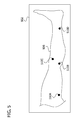
FIG. 5 is a front view of a fit indicator according to an embodiment of the invention; -
FIG. 6A is an exemplary flowchart for generating compliance efficiency data according to an embodiment of the invention; -
FIG. 6B is an exemplary flowchart for monitoring compliance according to an embodiment of the invention; -
FIG. 7 is an enlarged section taken in theplane 7--7 ofFIG. 3 according to an embodiment of the invention; and -
FIG. 8 is a top view of overlapping conductive strips to illustrate relative alignment and overlap of the conductive strips according to an embodiment of the invention. -
FIG. 1 conceptually illustrates a system, generally designated 100, for applying compression treatment to a patient according to an embodiment of the invention. Thesystem 100 comprises acompression garment 102, acontroller 104, and apump 106. Thecontroller 104 controls operation of thepump 106 to selectively inflate thegarment 102 via tubing connected to an outlet port (also designated by reference character 106). Thecontroller 104 is also adapted to receive signals from multiple fit sensors S1-SN and to indicate, via afit indicator 108, a fit ofgarment 102 during use on a patient as a function of signals generated by the fit sensors S1-SN. - Referring to
FIG. 2 , a compression garment embodying aspects of the invention is designated generally 202 and is illustrated in an unwrapped configuration.FIG. 3 , on the other hand, illustrates thegarment 202 as worn on a patient's body part in a wrapped configuration during use for applying intermittent, selective compression. As shown inFIG. 3 ,garment 202 is worn on the patient's leg, for example. - Referring again to
FIG. 2 ,compression garment 202 comprises one or more inflatable bladders (not shown) for selectively applying compression to the patient's body part (e.g., leg). Any number, shape, and configuration of the inflatable bladders is within the scope of the invention. Thegarment 202 also comprises one or more sets offasteners 204A-D, 212A-D for securing the garment in place on the patient in a self-retaining configuration.FIG. 2 illustrates hook (204A-D) and corresponding loop (212A-D) tabs for this purpose. Alternatively, the fasteners may include other means such as buckles and/or hook and loop wraps. Any positioning device is within the scope of the invention. - Desirably,
garment 202 has one or more specified areas of local fit. As described above, an ill fitted garment wastes precious air volume and pump energy for filling undesirable gaps. Thegarment 202 also includes a fit optimizing mechanism adapted for use when the garment is placed on the patient. In one embodiment, the fit optimizing mechanism comprisesfit sensors 224A-D, afit indicator panel 240,conductive traces 242, and acontroller 244. As will be described in detail later, signals from thefit sensors 224A-D are monitored to establish, improve, and/or monitor fit ofgarment 202 on the leg of the patient. In the illustrated embodiment, each area of local fit has a fit sensor (e.g. 224A) and a corresponding fastener (204A, 212A) formed in its immediate vicinity for adjustment and monitoring during use. Such areas relate to typical voids formed whengarment 202 is placed on the patient. As best illustrated inFIGS. 2 and3 , examples of such areas of fit for a leg may include the top of the calf when a leg sleeve is used (fastener sensor 224C), between the calf and the ankle (fastener sensor 224D), and both the top (fastener sensor 224A) and bottom (fastener sensor 224B) of the thigh when a thigh compression bladder is used.FIG. 3 generally illustratessensors 224A-D formed at each of these locations as indicated by the abovementioned reference characters. In an embodiment, each inflatable bladder ofgarment 202 may have a sensor formed thereon. Variations of the garment design (e.g., number and shape of bladders, placement of fasteners, etc.) are within the scope of the invention. - The
garment 202 further comprises thecompression controller 244 attached or otherwise integrated thereon for operating the garment. Thecontroller 244 is preferably sized for ease of use and without being cumbersome or a hindrance to patient mobility. Thecontroller 244 also preferably comprises the pump/port 106 (seeFIG.1 ) for delivering pressurized air togarment 202, and associated tubing (not shown) for delivering the pressurized air to the garment. Alternatively, as illustrated inFIG. 1 , the pump may be formed on the garment separate from the controller (e.g., pump 106 and controller 104). The tubing is desirably flush with the surface of the garment or hidden within the garment, and may be elastic in nature to accommodate stretching due to patient movement. Thecontroller 244 further comprises one or more processors (not shown) for performing various functions associated with operating thegarment 202, including (but not limited to) garment fit sensing and monitoring, patient compliance, etc. Preferably, a protectivehousing shields controller 244. Those skilled in the art are familiar with a variety of suitable processors for implementing the control and monitoring functions ofcontroller 244. Desirably, the processor ofcontroller 244 consumes minimal power and has a sleep mode. Also, the processor may be operable to accept analog inputs from sensors, such as capacitive frequency and/or current load, as well as digital inputs. The processor may also be capable of providing varied output, including display signals, audio signals, and historical information. Historical information may be utilized for measuring system parameters, such as efficacy. - Still referring to
FIG. 2 , one or more of thefit sensors 224A-D are formed ongarment 202 for evaluating fit of the garment on the patient. In a preferred embodiment,fit sensors 224A-D are patches of printed-on conductive elements, though other forms of sensors are within the scope of the invention. Thesensors 224A-D may be formed on or near the areas of local fit ofgarment 202. In this manner,sensors 224A-D may be used to evaluate and monitor fit in the most critical areas as specified by the garment manufacturer for efficient operation. - Each of the
sensors 224A-D are connected tocontroller 244 via the connecting elements or traces 242, as illustrated. Preferably, the connection is made via printed wiring, similar to PCB (Printed Circuit Board) technology, ongarment 202 itself. In this manner, the use of bulky and winding wires is eliminated, aiding the compaction ofgarment 202. Other means of connectingcontroller 244 tosensors 224A-D, including wireless means, are within the scope of the invention. - Referring now to
FIG. 4 , aspects of the invention are shown with respect to agarment 402. A radio frequency (RF) source ofcontroller 244 may be used to generate an RF signal for application tosensors 224A-D, thereby completing a RF circuit. In this manner, as best illustrated inFIG. 4 for asingle sensor 424, eachsensor 424 formed on thegarment 402 functions as a capacitive disk, also indicated byreference character 424. As thedisk 424 is moved closer to a patient's body part, as indicated at 426, the RF energy from thedisk 424 is absorbed into the patient as a function of agap 428 of spacing G1 as illustrated. This in turn creates a load in the RF circuit that varies according to the spacing G1, i.e., capacitive coupling ofdisk 424 to thepatient 426. The RF absorption current generated bydisk 424 is collected and monitored bycontroller 244, and an appropriate algorithm converts the current values to a fit value. In an embodiment, a current shunt delivers the RF fromcontroller 244 tocapacitive sensors 224A-D. Since the patient acts as a sink for the RF energy, a large level of circulating RF energy may be required to maintain the signal level of the RF circuit. Current shunts are beneficial for measurement and delivery of these large current values, and are further considered more accurate and economical than equivalent Hall effect current sensors, for example. - In an alternative embodiment, as
gap 428 varies, the frequency of the RF circuit formed by the RF source,disk 424, and patient 414, varies as a function of the gap 410. An appropriate algorithm then monitors the changing frequency to determine a fit value. - Referring again to
FIGS. 2 and3 , a fit value of the local fit ofgarment 202 around each ofsensors 224A-D, as well as a combined fit value corresponding to signals from allsensors 224A-D, may be calculated in any means possible. In a preferred embodiment, each of thesensors 224A-D is formed near acorresponding fastener 204A-D as illustrated, and corresponds to an area of desired local fit as discussed earlier. Fit is then evaluated by comparing the RF signal fromsensor 224A (for example) to an acceptable value for the corresponding area of local fit, and if the signal exceeds the known value (i.e., thresholding), an acceptable local fit forsensor 224A is indicated. - Fit may be indicated to a user by several means. In an embodiment, a visual indicator is employed. Referring to
FIGS. 2 and3 , and as best illustrated inFIG. 5 , a light emitting diode (LED)panel 502 is formed on thegarment 202 and operatively connected tocontroller 244. Thepanel 502 comprisesmultiple LEDs 510A-D, each corresponding to one of thecapacitive sensors 224A-D. As the RF signal fromsensor 224A (for example) reaches its acceptable value, the correspondingLED 510A lights up to indicate acceptable fit. The user adjustsfasteners 204A-D, 212A-D near thesensors 224A-D until all theLEDs 510A-D are lit, indicating that proper fit of thegarment 202 has been achieved. The LEDs 510-A-D may be arranged in any manner on thedisplay panel 502. A graphical overlay, for example, provides a visual indication mapping the location of each of theLEDs 510A-D tosensors 224A-D.FIG. 3 illustrates a preferred arrangement whereLEDs 510A-D are arranged to visually aid the user. In an alternative embodiment, the LED panel may be formed on the controller itself. In yet another embodiment, the visual indicator is integral to the controller, such as an LCD display on the body of the controller that may also include other controller features. - In an alternative embodiment, an audible indicator is employed to signal overall fit of
garment 202 as determined bysensors 224A-D. An audible tone heard by the user whilefitting garment 202 indicates optimum fit. As the overall fit (determined by calculating an overall fit value from all of thesensors 224A-D) improves, the tone increases in pitch perceptibly. When all of thesensors 224A-D detect acceptable fit, the tone goes silent. Other alternative modifications to the audible tone (e.g., volume, tone) to indicate change in fit are possible and within the scope of the invention. - A method of monitoring the use of
compression garment 202 ofFIGS. 2 and3 by a patient according to one aspect of the invention is generally illustrated inFIG. 6A . At 602,controller 244 ofgarment 202 receives the RF signal from one of thesensors 224A-D, such assensor 224A as described earlier. For the purpose of explanation onesensor 224A will be described, although the method is easily extensible tomultiple sensors 224A-D. As described earlier with respect toFIG. 4 , the received RF signal is indicative of the spacing G1 ofgap 428 betweensensor 424 andpatient body part 426. At 604, the RF signal is converted to capacitance, and at 606A,controller 244 compares the estimated capacitance versus an acceptable, threshold or recommended value. Thecontroller 244 then determines whether or notgarment 202 has an acceptable fit. - The
controller 244 concurrently monitors the use of garment 2020 by the user along with the RF signal fromsensor 224A at 606B. Monitoring of garment use may be performed by any means known in the art, including pressure sensors, temperature sensors, conductive hook and loop fasteners that complete an electrical circuit, and the like. In an example, pressure sensor data is used to determine the pressure applied as a measure of compliance. Then, at 610,controller 244 correlates the fit information fromsensor 224A with the compliance information to determine the efficacy of therapy, and/or the quality of compliance. -
FIG 6B illustrates an embodiment where the RF signal from one or more of thesensors 224A-D, such assensor 224A, may be used for compliance monitoring. During a compression cycle, the limb exerts comparatively greater pressure againstgarment 202 as a function of venous refill thereby reducing the spacing G1. That is, blood removed from a limb during a compression cycle returns to the limb thereafter. A measurable venous refill time (VRT) is associated with most compression therapies. This periodic change in the gap 410 caused by venous refill can be detected as periodic variations in the RF signal fromsensor 224A. Thecontroller 244 receives the RF signal at 620 fromsensor 224A and, at 624, monitors variations in the received RF signal over time. The VRT value can be calculated from these variations at 626. The calculated VRT is compared against normal values, 30-60 seconds for example, at 630. If the VRT is above the upper limit, it is assumed that the patient is not wearinggarment 202, and non-compliance is indicated at 632. - In an alternative or additional embodiment,
controller 244 is further operable to challenge the size of agarment 702 for the patient. As illustrated inFIG. 7 , this embodiment involves designing the fasteners of thegarment 702 as overlapping upper andlower tabs tabs 702A-B has aconductive strip tabs 702A-B may have hook and loop structures formed thereon, or other means of attachment to each other. Thestrips 706A-B align with each other during application ofgarment 702, forming in effect a variable capacitor. Increasing wrap of thegarment 702 leads to increased area of overlap OL between the conducting strips 706A-B, and hence leads to greater measured capacitance. Thecontroller 244 measures this capacitance and, if it exceeds a upper value (indicating significant overlap),controller 244 indicates to the user thatgarment 702 is too big for use. On the other hand, if the capacitance is too low (little overlap),controller 244 indicates to the user thatgarment 702 is too small, and that a larger size is recommended. - Additionally or alternatively, if
strips 706A-B are not aligned correctly, an error code is generated. In an embodiment such as illustrated inFIG. 8 , theconductive strips 806A-B (corresponding to conductive strips 706 A-B) are sufficiently narrow to effect a steep decrease in area of overlap OL' (corresponding to area OL) and the measured capacitance, if thecorresponding tabs 702A-B (not shown inFIG. 8 for clarity) are not aligned correctly. In an alternative embodiment (not shown), line markings on thetabs 702A-B are provided to aid the user in correct alignment of the fasteners. The measured capacitance is then a function of both the amount of overlap OL' and the correct alignment ofstrips 806A-B. As described above, an acceptable garment size and proper alignment are indicated to the user if this measured capacitance exceeds a threshold value. - Having described aspects of the invention in detail, it will be apparent that modifications and variations are possible without departing from the scope of the invention defined in the appended claims. For example,
sensors 224A-D are ideally sized to be small enough for effective local fit indication but large enough to generate discernable signals. Conductive traces 242 can also have a capacitive value, which may skew the measured capacitance. Thesensors 224A-D hence desirably have a large enough surface area to provide a significant component of the measured capacitance. In other words, a ratio between a surface area of thesensors 224A-D and a surface area of thetraces 242 will determine the signal-to-noise (SNR) of the invention. In an embodiment,sensors 224A-D are approximately 15mm diameter and disk-shaped. Alternatively, it is further possible forsensors 224A-D to be variably sized. In this manner, each sensor can be shaped and sized to conform to the specific area of fit measurement and monitoring. - As another example, the embodiments illustrated in
FIGS. 6A and6B may be combined, so that the RF signal fromsensor 224A may be used for both fit estimation and compliance monitoring to generate the compliance efficacy data ofFIG. 6A . This approach is beneficial for not requiring an additional sensor for determining compliance. - Referring again to
FIGS. 2 and3 ,sensors 224A-D andconductive traces 242 are preferably printed on elements as described. However, it is possible to design removable sensors that are attachable anywhere ongarment 202. This design is beneficial for flexible deployment ofsensors 224A-D. - Any suitable components may be used for constructing the printed on sensors and traces, given the requirements for flexibility, low profile and conductivity. In an embodiment,
fit sensors 224A-D are volume conductive films constructed as a single layer of carbon-loaded polyethylene, thereby providing the benefits of humidity-independence and biocompatibility. Conductive traces 242 may be constructed from conductive fabrics that provide elasticity, such as the Novonic® and Tex | mate® from Amphenol Corporation. Thedisplay panel 502 may be constructed from low-profile films. For example, Nanofilm provides ultra-thin conductive nanocomposites comprising conductive nanoparticles in a clear, invisible film as thin as 1 micron. The film is conductive and flexible. Interconnections between the various components may be made through conductive and adhesive components, such as the 3M™ Anisotropic Conductive Film (ACF) adhesives that consist of thermoplastic and thermoset adhesives randomly loaded with conductive particles. Alternatively, or in addition, simpler solutions such as conductive, adhesive tapes (e.g. 3M™ Electrically Conductive Adhesive Transfer Tape, or ECATT) may be used. - To improve the patient experience, there is a trend towards miniaturization, and smaller and lighter vascular compression systems are being developed that integrate all components onto the compression garment itself. This presents a whole group of unique challenges. There is a cascading set of limitations that are immediately apparent to those familiar with the art. The controller must be reduced in size to be a comfortable fit on the garment and the patient's limb. As a result, smaller valves reduce the amount of air sent to the bladder, resulting in smaller bladder volumes. Most importantly, it is critical that these smaller devices still provide sufficient compression for effective therapy despite more limited compression abilities.
- In view of the above, it will be seen that the several objects of the invention are achieved and other advantageous results attained. By initial and subsequent monitoring of the fit of the compression garments, it is assured that the compression garment, given its limited compression ability, is positioned to provide the most efficient transfer of compression forces possible to the patient. By placing multiple capacitive sensors in all areas of a garment deemed critical for establishing a proper fit, aspects of the invention can monitor areas that are not readily apparent to the user. By providing a visual and/or audio indicator, the user can readily receive feedback confirming or denying that a proper fit has been established. In this manner, the controller can be made operable if the garment is properly installed.
- In operation, use of
compression garment 202 by a patient is monitored by receiving signals generated by thecapacitive sensors 224A-D. The signals are generally indicative of gaps betweengarment 202 and the patient during use. The received signals are evaluated to determine an overall fit of thegarment 202 on the limb based on the gaps between the garment and the patient at each sensor location. The use ofgarment 202 by the patient is determined. Compliance efficacy data as a function of the determined overall fit and the determined garment use is then generated. - A system for applying compression treatment embodying aspects of the invention comprises a garment sized and shaped to be wrapped around substantially a body part of a wearer. The garment has one or more fasteners for securing the garment in a self-retaining wrapped configuration around the body part and one or more selectively inflatable bladders for applying compression to the body part upon inflation. The system also includes at least one capacitive sensor formed on the garment. The sensor generates a signal indicative of a gap between the garment and the body part when the garment is in the wrapped configuration. A compression control unit, which includes a pump for pressurizing fluid, delivers pressurized fluid to the inflatable bladders via an outlet port in fluid communication with the pump. The compression control unit also includes one or more processors receiving and responsive to the signal from the capacitive sensor for evaluating an overall fit of the garment on the body part based on the gap between the garment and the body part.
- The capacitive sensor may be a printed-on conductive element formed on the garment. Additionally or alternatively, each inflatable bladder has at least one capacitive sensor formed thereon. Additionally or alternatively, the garment comprises one or more areas of local fit, and wherein each area of local fit has at least one corresponding capacitive sensor formed thereon.
- Additionally or alternatively, an adjustable fastener is formed near each capacitive sensor to adjust the local fit of the garment in the vicinity of the corresponding capacitive sensor. The adjustable fastener may comprise at least one of the following: a hook and loop strap, a looped hook and loop strap, a hook and loop wrap, and a belt and buckle.
- Additionally or alternatively, the control unit further comprises a radio frequency (RF) signal generator for transmitting RF signals to each capacitive sensor. Each capacitive sensor generates RF absorption current as a function of the gap between the capacitive sensor and the body part, said RF absorption current being indicative of local fit of the garment in the vicinity of the capacitive sensor. Each capacitive sensor forms an oscillator circuit with the RF signal generator, wherein a resonant frequency of the oscillator circuit varies as a function of the gap between the capacitive sensor and the body part, said resonant frequency being indicative of local fit of the garment in the vicinity of the capacitive electrode.
- Additionally or alternatively, the control unit further comprises a fit indicator. The fit indicator may include a plurality of visual indicators. Each visual indicator corresponding to one of the capacitive sensors and is indicative of local fit of the garment in the vicinity of the corresponding capacitive sensor. The visual indicator may be a light emitting diode. Additionally or alternatively, the fit indicator is an audible tone that increases in pitch as a function of overall fit of the garment.
- In an aspect, a compression garment assembly includes a compression garment adapted for placement on a body part. The garment has at least one selectively inflatable bladder for applying compression to the body part upon inflation. The assembly also includes a plurality of capacitive sensors formed on the garment. Each capacitive sensor generates a signal indicative of a gap between the garment and the body part when the garment is placed thereon. The sensors define one or more areas of local fit specified for proper operation, each area having at least one of the plurality of capacitive sensors formed thereon. The generated signal from each of the capacitive sensors is indicative of a gap between the garment and the body part in the respective area of local fit. The assembly also includes a compression control unit for selectively inflating the bladder. A processor of the control unit is operatively connected to the plurality of capacitive sensors and configured for indicating proper fit of each of the one or more areas of local fit on the body part as a function of the generated signals from the capacitive sensors. In this manner, the compression garment assembly improves efficacy of compression treatment.
- The capacitive sensor may be a printed-on conductive element formed on the garment. Additionally or alternatively, an adjustable fastener is formed near each capacitive sensor to adjust the local fit of the corresponding area to achieve proper fit. The adjustable fastener may be at least one of the following: a hook and loop strap, a looped hook and loop strap, a hook and loop wrap, and a belt and buckle
- Additionally or alternatively, the compression garment further comprises a radio frequency (RF) signal generator for transmitting RF signals to each capacitive sensor. Each capacitive sensor generates RF absorption current as a function of the gap between the capacitive sensor and the body part of the patient in the corresponding area of local fit. Each capacitive sensor forms an oscillator circuit with the RF signal generator, wherein a resonant frequency of the oscillator circuit varies as a function of the gap between the capacitive sensor and the limb of the patient in the corresponding area of local fit.
- Additionally or alternatively, the controller further comprises a fit indicator. The fit indicator may include a plurality of visual indicators. Each visual indicator corresponding to one of the capacitive sensors and is indicative of local fit of the garment in the vicinity of the corresponding capacitive sensor. The visual indicator may be a light emitting diode. Additionally or alternatively, the fit indicator is an audible tone that increases in pitch as a function of overall fit of the garment.
- A method of monitoring use of a compression garment by a patient embodies further aspects of the invention. The method includes receiving a signal generated by a capacitive sensor formed on the garment, where the signal is indicative of a gap between the garment and the patient during use. The method also includes evaluating the signal from the one or more sensors to determine an overall fit of the garment on the limb based on the gap between the garment and the patient. And the method includes determining use of the compression garment by the patient and generating compliance efficacy data as a function of the determined overall fit and the determined garment use.
- Evaluating the signal may comprise determining if the garment is appropriately sized for the patient. Additionally or alternatively, the garment comprises an adjustable fastener securing the garment on the patient. The method may also include forming, by the adjustable fastener during use, a variable capacitor, and evaluating capacitance of the variable capacitor. The method may also include indicating that the garment is too big for the patient when the capacitance is greater than or equal to a predetermined maximum, and indicating that the garment is too small for the patient when the capacitance is less than or equal to a predetermined minimum. The method includes indicating that the garment is appropriately sized for the patient when the capacitance is between the prescribed maximum and the prescribed minimum.
- Additionally or alternatively, the adjustable fastener comprises a pair of overlapping hook and loop tabs, each tab having a conducting strip printed thereon. The evaluated capacitance is a function of an area of overlap between the conducting strips of the overlapping hook and loop tabs. The evaluated capacitance may further be a function of a relative alignment between the conducting strips of the overlapping hook and loop tabs.
- Additionally or alternatively, the compression garment comprises a plurality of critical areas of desirable fit. Each critical area has at least one capacitive sensor formed thereon, and overall fit of the garment is determined as a function of the plurality of sensors corresponding to the plurality of critical areas.
- Additionally or alternatively, the method further includes monitoring variations in the received signal from the capacitive sensor. The monitored variations are indicative of variations in the gap between the garment and the patient caused by systemic blood circulation in the patient. The method also includes calculating a venous refill time (VRT) value as a function of the monitored variations, and triggering a caution indicator indicative of non-compliance when the VRT value falls below a predetermined lower limit.
- When introducing elements of the present invention or the preferred embodiments(s) thereof, the articles "a", "an", "the" and "said" are intended to mean that there are one or more of the elements. The terms "comprising", "including" and "having" are intended to be inclusive and mean that there may be additional elements other than the listed elements.
- As various changes could be made in the above constructions, products, and methods without departing from the scope of the invention, it is intended that all matter contained in the above description and shown in the accompanying drawings shall be interpreted as illustrative and not in a limiting sense.
Claims (15)
- A system for applying compression treatment comprising:a garment sized and shaped to be wrapped around substantially a body part of a wearer, said garment comprising one or more selectively inflatable bladders for applying compression to the body part upon inflation;one or more fasteners for securing the garment in a self-retaining wrapped configuration around the body part;at least one capacitive sensor formed on the garment, said sensor generating a signal indicative of a gap between the garment and the body part when the garment is in the wrapped configuration; anda compression control unit, said control unit comprising:a pump for pressurizing fluid;an outlet port in fluid communication with the pump, said outlet port having fluid tubing connected thereto for delivering pressurized fluid to the inflatable bladders; andone or more processors receiving and responsive to the signal from the capacitive sensor for evaluating an overall fit of the garment on the body part based on the gap between the garment and the body part.
- The compression system of claim 1, wherein the capacitive sensor is a printed-on conductive element formed on the garment.
- The compression system of claim 1 or claim 2, wherein each inflatable bladder has at least one capacitive sensor formed thereon.
- The compression system of any of claims 1 to 3, wherein the garment comprises one or more areas of local fit, wherein each area of local fit has at least one corresponding capacitive sensor formed thereon, and wherein an adjustable fastener is formed near each capacitive sensor to adjust the local fit of the garment in the vicinity of the corresponding capacitive sensor.
- The compression system of any of claims 1 to 4, wherein:the control unit further comprises a radio frequency (RF) signal generator for transmitting RF signals to each capacitive sensor,each capacitive sensor forms an oscillator circuit with the RF signal generator,each capacitive sensor generates RF absorption current in the oscillator circuit as a function of the gap between the capacitive sensor and the body part,a resonant frequency of the oscillator circuit varies as a function of the gap between the capacitive sensor and the body part, andat least one of the RF absorption current and the resonant frequency is indicative of local fit of the garment in the vicinity of the capacitive sensor.
- The compression system of any of claims 1 to 5, wherein the control unit further comprises a fit indicator, said fit indicator comprising one or more of the following:a plurality of visual indicators, each of said visual indicators corresponding to one of the capacitive sensors and being indicative of local fit of the garment in the vicinity of the corresponding capacitive sensor; andan audible tone that increases in pitch as a function of overall fit of the garment.
- A compression garment assembly comprising:a compression garment adapted for placement on a body part, said garment having at least one selectively inflatable bladder for applying compression to the body part upon inflation;a plurality of capacitive sensors formed on the garment, each of said capacitive sensors generating a signal indicative of a gap between the garment and the body part when the garment is placed thereon, said sensors defining one or more areas of local fit specified for proper operation, said areas each having at least one of the plurality of capacitive sensors formed thereon, wherein the generated signal from each of the capacitive sensors is indicative of a gap between the garment and the body part in the respective area of local fit; anda compression control unit for selectively inflating the bladder, said control unit comprising a processor operatively connected to the plurality of capacitive sensors, said processor configured for indicating proper fit of each of the one or more areas of local fit on the body part as a function of the generated signals from the plurality of capacitive sensors and thereby improving efficacy of compression treatment.
- The compression garment of claim 7, wherein an adjustable fastener is formed near each capacitive sensor to adjust the local fit of the corresponding area to achieve proper fit.
- The compression garment of claim 7 or claim 8, further comprising a radio frequency (RF) signal generator for transmitting RF signals to each capacitive sensor, wherein each capacitive sensor forms an oscillator circuit with the RF signal generator, wherein each capacitive sensor generates RF absorption current in the oscillator circuit as a function of the gap between the capacitive sensor and the body part of the patient in the corresponding area of local fit, and wherein a resonant frequency of the oscillator circuit varies as a function of the gap between the capacitive sensor and the limb of the patient in the corresponding area of local fit.
- The compression garment of any of claims 7 to 9, wherein the controller further comprises a fit indicator, said fit indicator comprising one or more of the following:a plurality of visual indicators, each of said visual indicators corresponding to one of the plurality of capacitive sensors and being indicative of proper fit of the garment in the corresponding area of local fit; andan audible tone that increases in pitch as a function of overall fit of the compressive garment to the limb.
- A method of monitoring use of a compression garment by a patient, said method comprising:receiving a signal generated by a capacitive sensor formed on the garment, said signal being indicative of a gap between the garment and the patient during use;evaluating said signal from the one or more sensors to determine an overall fit of the garment on the limb based on the gap between the garment and the patient;determining use of the compression garment by the patient; andgenerating compliance efficacy data as a function of the determined overall fit and the determined garment use.
- The method of claim 11, wherein said garment comprises an adjustable fastener securing the garment on the patient, wherein said evaluating further comprises determining if the garment is appropriately sized for the patient, said determining comprising:forming, by the adjustable fastener during use, a variable capacitor;evaluating capacitance of the variable capacitor;indicating that the garment is too big for the patient when the capacitance is greater than or equal to a predetermined maximum;indicating that the garment is too small for the patient when the capacitance is less than or equal to a predetermined minimum; andindicating that the garment is appropriately sized for the patient when the capacitance is between the prescribed maximum and the prescribed minimum.
- The method of claim 12, wherein the adjustable fastener comprises a pair of overlapping hook and loop tabs, each tab having a conducting strip printed thereon, wherein the evaluated capacitance is a function of an area of overlap between the conducting strips of the overlapping hook and loop tabs, and wherein the evaluated capacitance is further a function of a relative alignment between the conducting strips of the overlapping hook and loop tabs.
- The method of any of claims 11 to 13, wherein the compression garment comprises a plurality of critical areas of desirable fit, wherein each critical area has at least one capacitive sensor formed thereon, wherein overall fit of the garment is determined as a function of the plurality of sensors corresponding to the plurality of critical areas.
- The method of any of claims 11 to 14, further comprising:monitoring variations in the received signal from the capacitive sensor, said monitored variations being indicative of variations in the gap between the garment and the patient caused by systemic blood circulation in the patient;calculating a venous refill time (VRT) value as a function of the monitored variations;
andtriggering a caution indicator indicative of non-compliance when the VRT value falls below a predetermined lower limit.
Applications Claiming Priority (1)
| Application Number | Priority Date | Filing Date | Title |
|---|---|---|---|
| US12/699,610 US8257289B2 (en) | 2010-02-03 | 2010-02-03 | Fitting of compression garment |
Publications (1)
| Publication Number | Publication Date |
|---|---|
| EP2359785A1 true EP2359785A1 (en) | 2011-08-24 |
Family
ID=43982231
Family Applications (1)
| Application Number | Title | Priority Date | Filing Date |
|---|---|---|---|
| EP11152713A Withdrawn EP2359785A1 (en) | 2010-02-03 | 2011-01-31 | Fitting of compression garment |
Country Status (7)
| Country | Link |
|---|---|
| US (1) | US8257289B2 (en) |
| EP (1) | EP2359785A1 (en) |
| JP (1) | JP2011156366A (en) |
| CN (1) | CN102188318A (en) |
| AU (1) | AU2011200419B2 (en) |
| BR (1) | BRPI1100197A2 (en) |
| CA (1) | CA2729396A1 (en) |
Cited By (7)
| Publication number | Priority date | Publication date | Assignee | Title |
|---|---|---|---|---|
| EP2436308A1 (en) * | 2010-09-30 | 2012-04-04 | Tyco Healthcare Group LP | Monitoring compliance using venous refill detection |
| US8257289B2 (en) | 2010-02-03 | 2012-09-04 | Tyco Healthcare Group Lp | Fitting of compression garment |
| AU2011224014B2 (en) * | 2010-09-29 | 2013-01-10 | Covidien Lp | Compression garment apparatus having baseline pressure |
| EP2727572A1 (en) * | 2012-10-17 | 2014-05-07 | Caremed Supply, Inc. | Inflatable cuff with automatic tightness detection |
| US8758282B2 (en) | 2010-09-29 | 2014-06-24 | Covidien Lp | Compression garment apparatus having support bladder |
| AU2013202854B2 (en) * | 2010-09-29 | 2014-06-26 | Kpr U.S., Llc | Compression garment apparatus having baseline pressure |
| US11077011B2 (en) | 2015-10-09 | 2021-08-03 | Kpr U.S., Llc | Compression garment compliance |
Families Citing this family (51)
| Publication number | Priority date | Publication date | Assignee | Title |
|---|---|---|---|---|
| ATE397912T1 (en) | 2004-10-11 | 2008-07-15 | Smm Medical Ab | ELECTROACTIVE COMPRESSION BANDAGE |
| BRPI0621229A2 (en) | 2006-01-13 | 2011-12-06 | Smm Medical Ab | device and system for compression treatment of a body part |
| MX2009007537A (en) | 2007-01-24 | 2010-02-24 | Convatec Technologies Inc | An elastomeric particle having an electrically conducting surface, a pressure sensor comprising said particles, a method for producing said sensor and a sensor system comprising sais sensors. |
| US8497884B2 (en) | 2009-07-20 | 2013-07-30 | Motorola Mobility Llc | Electronic device and method for manipulating graphic user interface elements |
| US20120065561A1 (en) * | 2010-09-03 | 2012-03-15 | Epoch Medical Innovations, Inc. | Device, system, and method for the treatment, prevention and diagnosis of chronic venous insufficiency, deep vein thrombosis, lymphedema and other circulatory conditions |
| US8613762B2 (en) | 2010-12-20 | 2013-12-24 | Medical Technology Inc. | Cold therapy apparatus using heat exchanger |
| US20120165717A1 (en) * | 2010-12-22 | 2012-06-28 | Convatec Technologies Inc. | Medical compression product, system utilizing such product, and program for use therewith |
| US20130018291A1 (en) * | 2011-07-12 | 2013-01-17 | Robert Kraal | Apparatus for facilitating circulation |
| US10470667B2 (en) * | 2011-11-11 | 2019-11-12 | University Of Ireland, Galway | System for management and prevention of venous pooling |
| US11471231B2 (en) | 2012-02-14 | 2022-10-18 | Frederick H. Sklar | Therapeutic garment for treatment of over-shunting headaches and method for use of same |
| WO2013123243A1 (en) | 2012-02-14 | 2013-08-22 | Frederick Sklar | Therapeutic garment for treatment of over-shunting headaches and method for use of same |
| US9737454B2 (en) * | 2012-03-02 | 2017-08-22 | Hill-Rom Services, Inc. | Sequential compression therapy compliance monitoring systems and methods |
| US9566187B2 (en) | 2012-03-13 | 2017-02-14 | Breg, Inc. | Cold therapy systems and methods |
| US9114055B2 (en) | 2012-03-13 | 2015-08-25 | Cothera Llc | Deep vein thrombosis (“DVT”) and thermal/compression therapy systems, apparatuses and methods |
| EP2884894B1 (en) * | 2012-08-18 | 2021-06-16 | Tactile Systems Technology, Inc. | Methods for determining the size of body parts as part of compression therapy procedures |
| US9081542B2 (en) | 2012-08-28 | 2015-07-14 | Google Technology Holdings LLC | Systems and methods for a wearable touch-sensitive device |
| US9402763B2 (en) | 2012-09-12 | 2016-08-02 | Breg, Inc. | Cold therapy apparatus having heat exchanging therapy pad |
| US10688007B2 (en) | 2012-09-14 | 2020-06-23 | Recovery Force, LLC | Compression device |
| US10617593B2 (en) * | 2012-09-14 | 2020-04-14 | Recovery Force, LLC | Compression integument |
| US9956113B2 (en) * | 2013-03-12 | 2018-05-01 | The Board Of Trustees Of The Leland Stanford Junior University | Method and system for regulating core body temperature |
| US10058475B2 (en) | 2013-03-15 | 2018-08-28 | Innovamed Health, LLC | Portable intermittent pneumatic compression system |
| USD760728S1 (en) | 2013-06-17 | 2016-07-05 | Covidien Lp | Display screen with graphical user interface for patient use meter reset |
| USD737327S1 (en) | 2013-06-17 | 2015-08-25 | Covidien Lp | Display screen with a transitional leak detection icon |
| USD774057S1 (en) | 2013-06-17 | 2016-12-13 | Covidien Lp | Display screen with a graphical user interface for compliance monitoring |
| USD737328S1 (en) | 2013-06-17 | 2015-08-25 | Covidien Lp | Display screen with graphical user interface for venous refill detection |
| USD737855S1 (en) | 2013-06-17 | 2015-09-01 | Covidien Lp | Display screen with a transitional venous refill detection icon |
| US20150057585A1 (en) * | 2013-08-20 | 2015-02-26 | Covidien Lp | Compression device having compliance tracking |
| WO2015089383A1 (en) * | 2013-12-12 | 2015-06-18 | Advanze Cardio Systems, Llc | Compression therapy system and module |
| CN105455219B (en) * | 2014-09-09 | 2018-02-27 | 联想(北京)有限公司 | A kind of wearable device and data processing method |
| US10226211B2 (en) | 2014-10-11 | 2019-03-12 | Zimmer Dental, Ltd. | System and method for determining user's deep vein thrombosis prevention and diagnosis system utilization compliance |
| EP3240471A4 (en) * | 2014-11-05 | 2018-10-03 | The Regents of the University of California | Telemedical wearable sensing system for management of chronic venous disorders |
| JP6489422B2 (en) * | 2015-01-28 | 2019-03-27 | パナソニックIpマネジメント株式会社 | Assist wear, assist wear operating method, and control program |
| US10973413B2 (en) * | 2015-10-07 | 2021-04-13 | Fiomet Ventures, Inc. | Advanced compression garments and systems |
| CN105797280A (en) * | 2016-03-08 | 2016-07-27 | 首都医科大学附属北京朝阳医院 | Deep venous embolism prevention and treatment apparatus |
| EP3448330A4 (en) | 2016-04-27 | 2019-11-06 | Radial Medical, Inc. | ADAPTIVE COMPRESSOTHERAPY SYSTEMS AND METHODS |
| CN106038201A (en) * | 2016-07-11 | 2016-10-26 | 广州彩磁信息技术有限公司 | Bionic rhythmical diastole and systole type wearable device capable of promoting lymph and vein circulation |
| US12076292B2 (en) * | 2017-02-28 | 2024-09-03 | Zoll Medical Corporation | Force sensing implementations in cardiopulmonary resuscitation |
| US10434033B2 (en) | 2017-11-01 | 2019-10-08 | Vena Group, LLC | Portable, reusable, and disposable intermittent pneumatic compression system |
| US11364174B2 (en) * | 2017-12-01 | 2022-06-21 | Arizona Board Of Regents On Behalf Of Arizona State University | Cold therapy dynamic hand splint system |
| US11622883B2 (en) | 2019-01-31 | 2023-04-11 | Flotherm, Inc. | Patient temperature and blood flow management |
| US12403034B2 (en) | 2019-01-31 | 2025-09-02 | Flotherm, Inc. | Sleeve-based body temperature regulation |
| WO2020185199A1 (en) * | 2019-03-08 | 2020-09-17 | Medi Usa, L.P. | Pneumatic compression systems and compression treatment methods |
| CN114423307A (en) * | 2019-05-31 | 2022-04-29 | 耐克创新有限合伙公司 | Adaptive support garment system and method |
| CN112426343A (en) * | 2020-11-17 | 2021-03-02 | 厦门大学附属第一医院 | Portable device for preventing deep venous embolism of double lower limbs |
| US12502308B2 (en) | 2021-07-01 | 2025-12-23 | Flotherm, Inc. | Flexible heating pads |
| CN118613238A (en) * | 2021-10-11 | 2024-09-06 | 侒捷祐知识产权控股有限公司 | Control unit, system and method for analyzing the use of compression therapy |
| US12226369B2 (en) * | 2021-12-28 | 2025-02-18 | JKH Health Co., Ltd. | Pneumatic therapy apparatus and method |
| US12083052B2 (en) | 2022-11-07 | 2024-09-10 | Frederick H. Sklar | Surgical universal headrest including skull pin holder assembly |
| US12082981B2 (en) | 2022-11-07 | 2024-09-10 | Frederick H. Sklar | Surgical armrest |
| US12345373B2 (en) | 2022-11-07 | 2025-07-01 | Frederick H. Sklar | Base station assembly for an operating room table |
| JP2025538502A (en) * | 2022-11-18 | 2025-11-28 | ケーピーアール ユー.エス.,エルエルシー | Systems, methods and devices for monitoring and expressing compliance with medical treatments |
Citations (5)
| Publication number | Priority date | Publication date | Assignee | Title |
|---|---|---|---|---|
| WO2000000155A1 (en) * | 1996-04-29 | 2000-01-06 | Abatis Medical Technologies Limited | Apparatus and method for monitoring pneumatic limb compression therapy |
| WO2003007855A1 (en) * | 2001-07-20 | 2003-01-30 | Huntleigh Technology Plc | An inflatable apparatus |
| US6736787B1 (en) * | 1996-04-29 | 2004-05-18 | Mcewen James Allen | Apparatus for applying pressure waveforms to a limb |
| US20040127937A1 (en) * | 1998-07-25 | 2004-07-01 | Newton Michael David | Identification and communication system for inflatable devices |
| US20090234265A1 (en) * | 2008-03-13 | 2009-09-17 | Reid Jr Lawrence G | Compression Adjustable Fabric and Garments |
Family Cites Families (95)
| Publication number | Priority date | Publication date | Assignee | Title |
|---|---|---|---|---|
| US3866604A (en) * | 1973-09-28 | 1975-02-18 | Avco Everett Res Lab Inc | External cardiac assistance |
| US4016868A (en) * | 1975-11-25 | 1977-04-12 | Allison Robert D | Garment for impedance plethysmograph use |
| US4353359A (en) * | 1979-07-16 | 1982-10-12 | Milbauer Nathaniel A | Portable jacket for treatment and protection of injured body members |
| US4396010A (en) * | 1980-06-30 | 1983-08-02 | The Kendall Company | Sequential compression device |
| US4469099A (en) * | 1980-10-02 | 1984-09-04 | Western Clinical Engineering Ltd. | Pneumatic torniquet |
| US4492234A (en) * | 1981-07-02 | 1985-01-08 | The Kendall Company | Pressure measurement method |
| US4605010A (en) * | 1984-05-17 | 1986-08-12 | Western Clinical Engineering Ltd. | Pressurizing cuff |
| US4624244A (en) * | 1984-10-15 | 1986-11-25 | Taheri Syde A | Device for aiding cardiocepital venous flow from the foot and leg of a patient |
| US4671290A (en) * | 1985-01-15 | 1987-06-09 | Richards Medical Company | Automatic tourniquet |
| US5474083A (en) * | 1986-12-08 | 1995-12-12 | Empi, Inc. | Lifting monitoring and exercise training system |
| US5010893A (en) * | 1987-01-15 | 1991-04-30 | Siemens-Pacesetter, Inc. | Motion sensor for implanted medical device |
| US5050613A (en) * | 1989-09-15 | 1991-09-24 | Imex Corporation | Method and apparatus for vascular testing |
| US5103833A (en) * | 1989-12-20 | 1992-04-14 | Critikon, Inc. | Peripheral arterial monitoring instruments |
| US5929782A (en) * | 1990-02-21 | 1999-07-27 | Stark; John G. | Communication system for an instrumented orthopedic restraining device and method therefor |
| US5052375A (en) * | 1990-02-21 | 1991-10-01 | John G. Stark | Instrumented orthopedic restraining device and method of use |
| US5167237A (en) * | 1991-07-09 | 1992-12-01 | Long Island Jewish Medical Center | Apparatus for monitoring detrusor pressure exerted by a bladder |
| US5331548A (en) * | 1991-10-28 | 1994-07-19 | Rollema Harm J | Method and system for on-line measurement, storage, retrieval and analysis of urodynamical data |
| US6468237B1 (en) * | 1991-12-17 | 2002-10-22 | Kinetic Concepts, Inc. | Pneumatic pump, housing and methods for medical purposes |
| US5233987A (en) * | 1992-07-09 | 1993-08-10 | Empi, Inc. | System and method for monitoring patient's compliance |
| US5284133A (en) * | 1992-07-23 | 1994-02-08 | Armstrong Pharmaceuticals, Inc. | Inhalation device with a dose-timer, an actuator mechanism, and patient compliance monitoring means |
| US5514079A (en) * | 1992-08-11 | 1996-05-07 | Dillon; Richard S. | Method for promoting circulation of blood |
| US5443440A (en) * | 1993-06-11 | 1995-08-22 | Ndm Acquisition Corp. | Medical pumping apparatus |
| US5459700A (en) * | 1993-11-22 | 1995-10-17 | Advanced Cardiovascular Systems, Inc. | Manual timer control for inflation device |
| US5575762A (en) * | 1994-04-05 | 1996-11-19 | Beiersdorf-Jobst, Inc. | Gradient sequential compression system and method for reducing the occurrence of deep vein thrombosis |
| US5591200A (en) * | 1994-06-17 | 1997-01-07 | World, Inc. | Method and apparatus for applying pressure to a body limb for treating edema |
| JP3121353B2 (en) * | 1995-02-27 | 2000-12-25 | メドトロニック・インコーポレーテッド | External patient reference sensor |
| US5640953A (en) | 1995-03-09 | 1997-06-24 | Siemens Medical Systems, Inc. | Portable patient monitor reconfiguration system |
| US5718232A (en) * | 1995-06-07 | 1998-02-17 | Vasocor, Inc. | Calibration of segmental blood volume changes in arteries and veins for pulse volume recorder |
| US5840049A (en) * | 1995-09-07 | 1998-11-24 | Kinetic Concepts, Inc. | Medical pumping apparatus |
| US6387065B1 (en) * | 1996-09-30 | 2002-05-14 | Kinetic Concepts, Inc. | Remote controllable medical pumping apparatus |
| US5806512A (en) * | 1996-10-24 | 1998-09-15 | Life Support Technologies, Inc. | Cardiac/pulmonary resuscitation method and apparatus |
| US6047203A (en) * | 1997-03-17 | 2000-04-04 | Nims, Inc. | Physiologic signs feedback system |
| EP1019007B1 (en) * | 1997-08-18 | 2006-11-29 | CPCA2000, Inc. | Counterpulsation device using noncompressed air |
| US6135106A (en) * | 1997-08-22 | 2000-10-24 | Nellcor Puritan-Bennett, Inc. | CPAP pressure and flow transducer |
| US6381482B1 (en) * | 1998-05-13 | 2002-04-30 | Georgia Tech Research Corp. | Fabric or garment with integrated flexible information infrastructure |
| US5968073A (en) * | 1997-11-17 | 1999-10-19 | Jacobs; Laura F. | Methods and apparatus for applying pressure |
| US6188407B1 (en) * | 1998-03-04 | 2001-02-13 | Critikon Company, Llc | Reconfigurable user interface for modular patient monitor |
| US6045513A (en) * | 1998-05-13 | 2000-04-04 | Medtronic, Inc. | Implantable medical device for tracking patient functional status |
| US5982285A (en) * | 1998-05-14 | 1999-11-09 | Bueche; Kenneth M. | Compliance monitoring system |
| GB9816173D0 (en) * | 1998-07-25 | 1998-09-23 | Huntleigh Technology Plc | Pneumatic systems |
| US6231532B1 (en) * | 1998-10-05 | 2001-05-15 | Tyco International (Us) Inc. | Method to augment blood circulation in a limb |
| US6171270B1 (en) * | 1999-01-19 | 2001-01-09 | Jun-Shyan Gau | Apparatus for distributed air pressure massage |
| US6051016A (en) * | 1999-03-29 | 2000-04-18 | Instrumed, Inc. | System and method of controlling pressure in a surgical tourniquet |
| US6416471B1 (en) * | 1999-04-15 | 2002-07-09 | Nexan Limited | Portable remote patient telemonitoring system |
| US6200265B1 (en) * | 1999-04-16 | 2001-03-13 | Medtronic, Inc. | Peripheral memory patch and access method for use with an implantable medical device |
| US6616579B1 (en) * | 1999-06-14 | 2003-09-09 | Sensorpad Systems, Inc. | Apparatus for isometric exercise |
| US6527711B1 (en) * | 1999-10-18 | 2003-03-04 | Bodymedia, Inc. | Wearable human physiological data sensors and reporting system therefor |
| DE60106141T2 (en) * | 2000-02-04 | 2005-02-10 | Medtronic, Inc., Minneapolis | INFORMATION OBSERVATION DEVICE FOR MEDICAL DEVICE |
| IL152300A0 (en) * | 2000-04-17 | 2003-05-29 | Vivometrics Inc | Systems and methods for ambulatory monitoring of physiological signs |
| US6514200B1 (en) * | 2000-05-17 | 2003-02-04 | Brava, Llc | Patient compliance monitor |
| US20040054306A1 (en) * | 2002-01-11 | 2004-03-18 | Roth Rochelle B. | Inflatable massage garment |
| US7771376B2 (en) * | 2000-06-02 | 2010-08-10 | Midtown Technology Ltd. | Inflatable massage garment |
| US6338719B1 (en) * | 2000-06-12 | 2002-01-15 | Rutgers, The State University Of New Jersey | Method and system for detecting vascular conditions using an occlusive arm cuff plethysmograph |
| US6436058B1 (en) * | 2000-06-15 | 2002-08-20 | Dj Orthopedics, Llc | System and method for implementing rehabilitation protocols for an orthopedic restraining device |
| US20020087054A1 (en) * | 2001-01-03 | 2002-07-04 | Wen-Guai Lin | System and a method for monitoring the effectiveness of a medical treatment |
| US6775577B2 (en) * | 2001-07-18 | 2004-08-10 | Fresenius Usa, Inc. | Method and system for controlling a medical device |
| AUPR694401A0 (en) * | 2001-08-10 | 2001-09-06 | University Of Wollongong, The | Bio-mechanical feedback device |
| WO2003017885A1 (en) * | 2001-08-27 | 2003-03-06 | M.D. Brothers, Inc. | Automatic apparatus and method for treating carpal tunnel syndrome |
| US7118534B2 (en) * | 2001-09-21 | 2006-10-10 | Virginia Commonwealth University | Methods for monitoring and optimizing central venous pressure and intravascular volume |
| US20030125649A1 (en) * | 2001-10-31 | 2003-07-03 | Mcintosh Laura Janet | Method and system apparatus using temperature and pressure for treating medical disorders |
| US7033539B2 (en) * | 2002-05-24 | 2006-04-25 | Baxter International Inc. | Graphical user interface for automated dialysis system |
| EP1525024A1 (en) * | 2002-06-12 | 2005-04-27 | JOHNSON, James P. | Compression garment with electro-stimulation |
| US7491182B2 (en) * | 2002-11-15 | 2009-02-17 | Hill-Rom Services, Inc. | High frequency chest wall oscillation apparatus having plurality of modes |
| US20040111048A1 (en) * | 2002-12-04 | 2004-06-10 | Jensen Jeffrey L. | Compression device for treatment of chronic venous insufficiency |
| GB0307097D0 (en) * | 2003-03-27 | 2003-04-30 | Bristol Myers Squibb Co | Compression device for the limb |
| US6858012B2 (en) * | 2003-03-28 | 2005-02-22 | Applied Cardiac Systems, Inc. | System and method for generating external counterpulsation reports |
| US7244225B2 (en) * | 2003-10-07 | 2007-07-17 | Cardiomedics, Inc. | Devices and methods for non-invasively improving blood circulation |
| US7637879B2 (en) * | 2003-12-29 | 2009-12-29 | Medical Compression Systems, (Dbn) Ltd. | Method and apparatus for assisting vascular flow through external compression synchronized with venous phasic flow |
| US7354410B2 (en) * | 2004-02-23 | 2008-04-08 | Tyco Healthcare Group Lp | Compression treatment system |
| US7426157B2 (en) * | 2004-03-04 | 2008-09-16 | Nathan James Arnold | Electronic practice device |
| JP4665201B2 (en) * | 2004-05-04 | 2011-04-06 | アシスト・メディカル・システムズ・インコーポレーテッド | Method and system for using a graphical user interface for a multiple fluid injection device |
| US7214192B2 (en) * | 2004-09-07 | 2007-05-08 | Biomedix, Inc. | Vascular testing system |
| US20060058716A1 (en) * | 2004-09-14 | 2006-03-16 | Hui John C K | Unitary external counterpulsation device |
| EP1645254A1 (en) | 2004-10-11 | 2006-04-12 | SMM Medical AB | Electro active compression bandage |
| GB0423410D0 (en) | 2004-10-21 | 2004-11-24 | Bristol Myers Squibb Co | Compression device for the limb |
| US20060122544A1 (en) * | 2004-12-03 | 2006-06-08 | Gary Ciluffo | Therapeutic "smart" fabric garment including support hose, body garments, and athletic wear |
| US20080188781A1 (en) * | 2005-01-04 | 2008-08-07 | Steve Carkner | Therapy device for biomechanical rehabilitation massage |
| TW200701946A (en) * | 2005-07-06 | 2007-01-16 | Cardio Vascular Metrics Inc | Diagnostic device and the method using the same |
| GB0515040D0 (en) * | 2005-07-21 | 2005-08-31 | Bristol Myers Squibb Co | Compression device for the limb |
| CN101313194B (en) | 2005-10-13 | 2010-09-08 | 联邦科学和工业研究组织 | Systems and garments for detecting motion |
| US7931606B2 (en) * | 2005-12-12 | 2011-04-26 | Tyco Healthcare Group Lp | Compression apparatus |
| GB0601453D0 (en) * | 2006-01-24 | 2006-03-08 | Bristol Myers Squibb Co | Pressurised medical device |
| GB0603564D0 (en) * | 2006-02-23 | 2006-04-05 | Huntleigh Technology Plc | Automatic ankle brachial pressure index system |
| JP4839179B2 (en) * | 2006-10-18 | 2011-12-21 | 敏明 中島 | Treatment system, treatment apparatus, and control method |
| US8147417B2 (en) * | 2007-01-23 | 2012-04-03 | Ohk Medical Devices Ltd. | Tourniquet timer |
| US20080183095A1 (en) * | 2007-01-29 | 2008-07-31 | Austin Colby R | Infant monitor |
| US7945461B2 (en) * | 2007-02-15 | 2011-05-17 | Vivonex, L.L.C. | Prescription compliance monitoring system |
| US8016779B2 (en) * | 2007-04-09 | 2011-09-13 | Tyco Healthcare Group Lp | Compression device having cooling capability |
| US8060175B2 (en) * | 2007-06-15 | 2011-11-15 | General Electric Company | System and apparatus for collecting physiological signals from a plurality of electrodes |
| US10702174B2 (en) * | 2007-06-27 | 2020-07-07 | Integra Lifesciences Corporation | Medical monitor user interface |
| US8657772B2 (en) * | 2007-07-20 | 2014-02-25 | össur hf. | Wearable device having feedback characteristics |
| US20090048525A1 (en) * | 2007-08-14 | 2009-02-19 | Biomedix, Inc. | Venous refill testing system and method |
| US8751254B2 (en) * | 2007-08-27 | 2014-06-10 | Summa Health Systems | Method and apparatus for monitoring and systematizing rehabilitation data |
| US8257289B2 (en) | 2010-02-03 | 2012-09-04 | Tyco Healthcare Group Lp | Fitting of compression garment |
| US8506507B2 (en) | 2010-03-09 | 2013-08-13 | Covidien Lp | Venous augmentation system |
-
2010
- 2010-02-03 US US12/699,610 patent/US8257289B2/en active Active
-
2011
- 2011-01-26 CA CA2729396A patent/CA2729396A1/en not_active Abandoned
- 2011-01-31 EP EP11152713A patent/EP2359785A1/en not_active Withdrawn
- 2011-02-01 AU AU2011200419A patent/AU2011200419B2/en not_active Expired - Fee Related
- 2011-02-01 CN CN2011100725587A patent/CN102188318A/en active Pending
- 2011-02-02 BR BRPI1100197-6A patent/BRPI1100197A2/en not_active IP Right Cessation
- 2011-02-02 JP JP2011021198A patent/JP2011156366A/en not_active Withdrawn
Patent Citations (5)
| Publication number | Priority date | Publication date | Assignee | Title |
|---|---|---|---|---|
| WO2000000155A1 (en) * | 1996-04-29 | 2000-01-06 | Abatis Medical Technologies Limited | Apparatus and method for monitoring pneumatic limb compression therapy |
| US6736787B1 (en) * | 1996-04-29 | 2004-05-18 | Mcewen James Allen | Apparatus for applying pressure waveforms to a limb |
| US20040127937A1 (en) * | 1998-07-25 | 2004-07-01 | Newton Michael David | Identification and communication system for inflatable devices |
| WO2003007855A1 (en) * | 2001-07-20 | 2003-01-30 | Huntleigh Technology Plc | An inflatable apparatus |
| US20090234265A1 (en) * | 2008-03-13 | 2009-09-17 | Reid Jr Lawrence G | Compression Adjustable Fabric and Garments |
Cited By (14)
| Publication number | Priority date | Publication date | Assignee | Title |
|---|---|---|---|---|
| US8257289B2 (en) | 2010-02-03 | 2012-09-04 | Tyco Healthcare Group Lp | Fitting of compression garment |
| US8753300B2 (en) | 2010-09-29 | 2014-06-17 | Covidien Lp | Compression garment apparatus having baseline pressure |
| AU2011224014B2 (en) * | 2010-09-29 | 2013-01-10 | Covidien Lp | Compression garment apparatus having baseline pressure |
| AU2011224014B9 (en) * | 2010-09-29 | 2013-05-23 | Covidien Lp | Compression garment apparatus having baseline pressure |
| US8758282B2 (en) | 2010-09-29 | 2014-06-24 | Covidien Lp | Compression garment apparatus having support bladder |
| AU2013202854B2 (en) * | 2010-09-29 | 2014-06-26 | Kpr U.S., Llc | Compression garment apparatus having baseline pressure |
| US9421142B2 (en) | 2010-09-29 | 2016-08-23 | Covidien Lp | Compression garment apparatus having support bladder |
| US9717642B2 (en) | 2010-09-29 | 2017-08-01 | Covidien Lp | Compression garment apparatus having baseline pressure |
| EP2695574A1 (en) * | 2010-09-30 | 2014-02-12 | Covidien LP | Monitoring compliance using venous refill detection |
| EP2436308A1 (en) * | 2010-09-30 | 2012-04-04 | Tyco Healthcare Group LP | Monitoring compliance using venous refill detection |
| US10314531B2 (en) | 2010-09-30 | 2019-06-11 | Kpr U.S., Llc | Monitoring compliance using venous refill detection |
| US12274559B2 (en) | 2010-09-30 | 2025-04-15 | Kpr U.S., Llc | Control unit for monitoring patient compliance with a compression therapy regimen |
| EP2727572A1 (en) * | 2012-10-17 | 2014-05-07 | Caremed Supply, Inc. | Inflatable cuff with automatic tightness detection |
| US11077011B2 (en) | 2015-10-09 | 2021-08-03 | Kpr U.S., Llc | Compression garment compliance |
Also Published As
| Publication number | Publication date |
|---|---|
| CA2729396A1 (en) | 2011-08-03 |
| US8257289B2 (en) | 2012-09-04 |
| JP2011156366A (en) | 2011-08-18 |
| CN102188318A (en) | 2011-09-21 |
| AU2011200419A1 (en) | 2011-08-18 |
| AU2011200419B2 (en) | 2013-09-19 |
| US20110190675A1 (en) | 2011-08-04 |
| BRPI1100197A2 (en) | 2013-01-15 |
Similar Documents
| Publication | Publication Date | Title |
|---|---|---|
| US8257289B2 (en) | Fitting of compression garment | |
| US12274559B2 (en) | Control unit for monitoring patient compliance with a compression therapy regimen | |
| US7354410B2 (en) | Compression treatment system | |
| AU2005216923B2 (en) | Compression treatment system | |
| CN104755017B (en) | Monitoring system for determining the efficacy of a compression device | |
| AU2011221374B2 (en) | Compression garment apparatus having support bladder | |
| JP2023029597A (en) | Apparatus and methods of sensing patient condition, such as anatomy position, and apparatus and methods of controlling patient applications | |
| AU2013201701A1 (en) | Monitoring compliance using venous refill detection |
Legal Events
| Date | Code | Title | Description |
|---|---|---|---|
| PUAI | Public reference made under article 153(3) epc to a published international application that has entered the european phase |
Free format text: ORIGINAL CODE: 0009012 |
|
| AK | Designated contracting states |
Kind code of ref document: A1 Designated state(s): AL AT BE BG CH CY CZ DE DK EE ES FI FR GB GR HR HU IE IS IT LI LT LU LV MC MK MT NL NO PL PT RO RS SE SI SK SM TR |
|
| AX | Request for extension of the european patent |
Extension state: BA ME |
|
| 17P | Request for examination filed |
Effective date: 20120113 |
|
| RAP1 | Party data changed (applicant data changed or rights of an application transferred) |
Owner name: COVIDIEN LP |
|
| STAA | Information on the status of an ep patent application or granted ep patent |
Free format text: STATUS: THE APPLICATION IS DEEMED TO BE WITHDRAWN |
|
| 18D | Application deemed to be withdrawn |
Effective date: 20140801 |