EP2359624B1 - Enhancing outage capacity based on adaptive mode switching between on-frequency and frequency translation - Google Patents
Enhancing outage capacity based on adaptive mode switching between on-frequency and frequency translation Download PDFInfo
- Publication number
- EP2359624B1 EP2359624B1 EP08876285.1A EP08876285A EP2359624B1 EP 2359624 B1 EP2359624 B1 EP 2359624B1 EP 08876285 A EP08876285 A EP 08876285A EP 2359624 B1 EP2359624 B1 EP 2359624B1
- Authority
- EP
- European Patent Office
- Prior art keywords
- frequency
- mode
- mean
- outage capacity
- translated
- Prior art date
- Legal status (The legal status is an assumption and is not a legal conclusion. Google has not performed a legal analysis and makes no representation as to the accuracy of the status listed.)
- Not-in-force
Links
- 230000003044 adaptive effect Effects 0.000 title description 7
- 230000002708 enhancing effect Effects 0.000 title description 2
- 238000013519 translation Methods 0.000 title description 2
- 238000000034 method Methods 0.000 claims description 58
- 238000004891 communication Methods 0.000 claims description 45
- 238000012545 processing Methods 0.000 claims description 35
- 238000004590 computer program Methods 0.000 claims description 5
- 238000010586 diagram Methods 0.000 description 22
- 238000005562 fading Methods 0.000 description 9
- 238000005259 measurement Methods 0.000 description 8
- 230000014509 gene expression Effects 0.000 description 6
- 230000005540 biological transmission Effects 0.000 description 5
- 230000006870 function Effects 0.000 description 4
- 238000001914 filtration Methods 0.000 description 3
- 230000010287 polarization Effects 0.000 description 3
- 230000003068 static effect Effects 0.000 description 3
- 230000001360 synchronised effect Effects 0.000 description 3
- 230000001413 cellular effect Effects 0.000 description 2
- 230000001419 dependent effect Effects 0.000 description 2
- 230000000007 visual effect Effects 0.000 description 2
- 101100398248 Arabidopsis thaliana KIN10 gene Proteins 0.000 description 1
- 101100366000 Caenorhabditis elegans snr-1 gene Proteins 0.000 description 1
- 101100419874 Caenorhabditis elegans snr-2 gene Proteins 0.000 description 1
- 101000835860 Homo sapiens SWI/SNF-related matrix-associated actin-dependent regulator of chromatin subfamily B member 1 Proteins 0.000 description 1
- 102100025746 SWI/SNF-related matrix-associated actin-dependent regulator of chromatin subfamily B member 1 Human genes 0.000 description 1
- 230000003321 amplification Effects 0.000 description 1
- 230000006399 behavior Effects 0.000 description 1
- 238000012512 characterization method Methods 0.000 description 1
- 238000013461 design Methods 0.000 description 1
- 230000007774 longterm Effects 0.000 description 1
- 238000010295 mobile communication Methods 0.000 description 1
- 238000012986 modification Methods 0.000 description 1
- 230000004048 modification Effects 0.000 description 1
- 238000012544 monitoring process Methods 0.000 description 1
- 238000003199 nucleic acid amplification method Methods 0.000 description 1
- 238000005457 optimization Methods 0.000 description 1
- 230000000737 periodic effect Effects 0.000 description 1
- 238000001228 spectrum Methods 0.000 description 1
- 238000005309 stochastic process Methods 0.000 description 1
Images


Classifications
-
- H—ELECTRICITY
- H04—ELECTRIC COMMUNICATION TECHNIQUE
- H04B—TRANSMISSION
- H04B7/00—Radio transmission systems, i.e. using radiation field
- H04B7/14—Relay systems
- H04B7/15—Active relay systems
- H04B7/155—Ground-based stations
- H04B7/15557—Selecting relay station operation mode, e.g. between amplify and forward mode, decode and forward mode or FDD - and TDD mode
-
- H—ELECTRICITY
- H04—ELECTRIC COMMUNICATION TECHNIQUE
- H04W—WIRELESS COMMUNICATION NETWORKS
- H04W72/00—Local resource management
- H04W72/50—Allocation or scheduling criteria for wireless resources
- H04W72/54—Allocation or scheduling criteria for wireless resources based on quality criteria
- H04W72/542—Allocation or scheduling criteria for wireless resources based on quality criteria using measured or perceived quality
-
- H—ELECTRICITY
- H04—ELECTRIC COMMUNICATION TECHNIQUE
- H04W—WIRELESS COMMUNICATION NETWORKS
- H04W84/00—Network topologies
- H04W84/02—Hierarchically pre-organised networks, e.g. paging networks, cellular networks, WLAN [Wireless Local Area Network] or WLL [Wireless Local Loop]
- H04W84/04—Large scale networks; Deep hierarchical networks
- H04W84/042—Public Land Mobile systems, e.g. cellular systems
- H04W84/047—Public Land Mobile systems, e.g. cellular systems using dedicated repeater stations
Definitions
- Implementations described herein relate generally to communication systems. More particularly, implementations described herein relate to a scheme for enhancing outage capacity in communication systems.
- devices may communicate with one another via an intermediary device.
- a wireless station and user equipment may communicate via a repeater.
- Repeaters may be divided into two types, namely, on-frequency repeaters (OFRs) and frequency translating repeaters (FTRs).
- OFRs on-frequency repeaters
- FTRs frequency translating repeaters
- An OFR transmits a repeated signal on the same frequency
- FTRs transmits a repeated signal on a different frequency relative to the frequency used when receiving.
- OFRs utilize only one frequency resource while FTRs utilize two frequency resources and, as such, lose fifty-percent of those frequency resources. In this regard, the loss of such resources has a negative impact on the data rate or throughput.
- Outage capacity is typically associated with slow fading channels where the channel remains constant over a number of transmissions. In this regard, outage capacity is concerned with maintaining a constant rate during non-outage periods.
- ergodic capacity is typically associated with fast fading channels where one transmission spans a number of coherence periods and equates to the ensemble average of the information rate.
- Existing techniques to enhance the outage capacity generally rely on a diversity method (e.g., interleaving, frequency hopping, transmit diversity, or macrodiversity).
- Existing repeaters are not designed to reduce the outage capacity experienced by a receiving station.
- existing repeaters do not adopt low complexity adaptive schemes that allow for outage capacity optimization and account for different signal strength levels from a repeater, as well as direct path levels from a transmitter.
- existing repeaters are not specifically designed to reduce the outage capacity experienced by a receiving station.
- WO 2005/064872 A1 relates to relay supported wireless communication to enhance communication performance by using cooperative relaying.
- a method may be performed by a device in a wireless network.
- the method may include receiving channel quality feedback information, calculating, based on the channel quality feedback information, an outage capacity associated with an on-frequency mode of operation and an outage capacity associated with a frequency-translated mode of operation, selecting the on-frequency mode of operation or the frequency-translated mode of operation that maximizes outage capacity based on the calculated outage capacities associated with the on-frequency and frequency translated modes of operation, and transmitting, to two or more other devices, a message indicating to operate in an on-frequency mode or a frequency-translated mode based on the selected on-frequency mode of operation or the frequency-translated mode of operation.
- a method may be performed by a device in a wireless network.
- the method may include transmitting, to another device, channel quality feedback information, receiving, from the other device, a message indicating to operate in an on-frequency mode or a frequency-translated mode, based on the transmitted channel quality feedback information, and operating, by the device, in the on-frequency mode or the frequency translated mode according to the message.
- a device in a wireless network may include one or more antennas and a processing system.
- the processing system may be configured to determine channel quality information, maximize an outage capacity by selecting an on-frequency mode of operation or a frequency translated mode of operation based on the channel quality information, and transmit, to two or more other devices, a message indicating to operate in an on-frequency mode or a frequency translated mode.
- a computer-readable medium may include instructions to receive channel quality information, calculate, based on the channel quality information, an outage capacity associated with an on-frequency mode of operation and an outage capacity associated with a frequency translated mode of operation, and determine which of the outage capacities associated with the on-frequency mode of operation and the frequency translated mode of operation maximizes outage capacity.
- a system may comprise a base station to receive channel quality information that includes statistical measurements of a channel, calculate, based on the channel quality information, an outage capacity associated with an on-frequency mode of operation and an outage capacity associated with a frequency-translated mode of operation, selecting the on-frequency mode of operation or the frequency-translated mode of operation that maximizes outage capacity, and transmit a message indicating a selection of the on-frequency mode of operation or the frequency-translated mode of operation to other devices in a wireless network, and the other devices adhere to the mode of operation indicated in the message.
- the concepts described herein relate to a communication system.
- the communication system is intended to be broadly interpreted to include any type of wireless network, such as a cellular network and/or a mobile network (e.g., Global System for Mobile Communications (GSM), Long Term Evolution (LTE), Wideband Code Division Multiple Access (WCDMA), Ultra Mobile Broadband (UMB), Universal Mobile Telecommunications Systems (UMTS), Code Division Multiple Access 2000 (CDMA2000), ad hoc networks, High-Speed Packet Access (HSPA), etc.), and a non-cellular network (e.g., Wireless Fidelity (Wi-Fi), Worldwide Interoperability for Microwave Access (WiMax), etc.).
- GSM Global System for Mobile Communications
- LTE Long Term Evolution
- WCDMA Wideband Code Division Multiple Access
- UMB Ultra Mobile Broadband
- UMTS Universal Mobile Telecommunications Systems
- CDMA2000 Code Division Multiple Access 2000
- HSPA High-Speed Packet Access
- Wi-Fi Wireless Fidelity
- WiMax Worldwide Inter
- the communication system may include a network in which one or multiple intermediate devices (e.g., a repeater, a relay, etc.) may be employed.
- intermediate devices e.g., a repeater, a relay, etc.
- the terms communication system and network may be used interchangeably throughout this description.
- Embodiments described herein may provide that a device of a communication system may signal other devices to adaptively switch between OFR and FTR modes.
- the adaptive switching between modes may be based on one or more criteria that yield the highest outage capacity.
- the one or more criteria may include channel quality information (e.g., mean signal-to-noise ratio (SNR)).
- the device may make other types of communication-related decisions (e.g., which frequency band(s) to utilize, power levels, selection of intermediate devices, etc.).
- SNR mean signal-to-noise ratio
- the device may make other types of communication-related decisions (e.g., which frequency band(s) to utilize, power levels, selection of intermediate devices, etc.).
- OFR/FTR mode signal e.g., a message
- the other devices may perform maximum ratio combining (MRC) or interference rejection combining (IRC) when in FTR mode.
- MRC maximum ratio combining
- IRC interference rejection combining
- the other devices may provide channel quality information
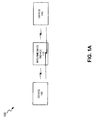
- Fig. 1A is a diagram illustrating an exemplary communication system 100 in which the concepts described herein may be implemented.
- communication system 100 may include a device 105, an intermediate device 110, and a device 115.
- a device i.e., device 105, intermediate device 110, and/or device 115
- the device may operate at layer 1, layer 2, and/or at a higher layer of a protocol stack.
- the devices may be communicatively coupled.
- the devices may be communicatively coupled via wireless communication links (e.g., radio, microwave, etc.).
- the number of devices illustrated in communication system 100 is exemplary, and in other instances, may be different.
- Fig. 1B illustrates an exemplary implementation in which device 105 includes a wireless station, intermediate device 110 includes a repeater, and device 115 includes a user equipment (UE).
- UE user equipment
- Wireless station 105, repeater 110 and UE 115 may be communicatively coupled.
- Wireless station 105 may include a device having communication capability.
- the term wireless station is intended to be broadly interpreted to include, for example, a device that may communicate with UE 115 via repeater 110.
- a wireless station may include a base station (BS), a base station transceiver (BTS) (e.g., in a GSM communication system), an eNodeB (e.g., in a LTE communication system), a Node B (e.g., in a UMTS communication system), or some other type of device.
- BTS base station transceiver
- eNodeB e.g., in a LTE communication system
- Node B e.g., in a UMTS communication system
- wireless station 105 may select, based on channel quality information, an OFR mode or an FTR mode for repeater 110 and UE 115 to operate.
- Wireless station 105 may signal repeater 110 and UE 115 indicating the mode of operation based on its selection.
- Repeater 110 may include a device having communication capability. Repeater 110 may be capable of switching between and operating in an OFR mode and an FTR mode.
- UE 115 may include a device having communication capability.
- UE 115 may include a telephone, a computer, a personal digital assistant (PDA), a gaming device, a music playing device, a video playing device, a web browser, a personal communication system (PCS) terminal, a pervasive computing device, and/or some other type of device.
- PDA personal digital assistant
- PCS personal communication system
- UE 115 may be capable of switching between and operating in an OFR mode and a FTR mode.
- wireless station 105 and UE 115 may be capable of performing functions that have been described as being performed by UE 115 and wireless station 105.
- UE 115 may select, based on channel quality information, an OFR mode or an FTR mode for wireless station 105 to operate, etc.
- Fig. 2A is a diagram illustrating exemplary components of wireless station 105.
- the term component is intended to be broadly interpreted to include, for example, hardware, software and hardware, firmware, software, or some other type of component and/or combination of components.
- wireless station 105 may include a processing system 200, a transceiver 205, an antenna 210, and a memory 215.
- Processing system 200 may include a component capable of interpreting and/or executing instructions.
- processing system 200 may include, a general-purpose processor, a microprocessor, a data processor, a co-processor, a network processor, an application specific integrated circuit (ASIC), a controller, a programmable logic device, a chipset, and/or a field programmable gate array (FPGA).
- ASIC application specific integrated circuit
- Processing system 200 may control one or more other components of wireless station 105.
- Processing system 200 may be capable of performing various communication-related processing (e.g., signal processing, channel estimation, beamforming, power control, scheduling, etc.).
- Transceiver 205 may include a component capable of transmitting and/or receiving information over wireless channels via antennas 210.
- transceiver 205 may include a transmitter and a receiver.
- Transceiver 205 may be capable of performing various communication-related processing (e.g., demodulation/modulation, deinterleaving/interleaving, equalizing, filtering, decoding/coding, signal measurement, etc.).
- Antenna 210 may include a component capable of receiving information and transmitting information via wireless channels.
- Antenna 210 may include a single or a multi-antenna system (e.g., a MIMO antenna system).
- Antenna 210 may provide one or more forms of diversity (e.g., spatial, pattern, or polarization).
- Memory 215 may include a component capable of storing information (e.g., data and/or instructions).
- memory 215 may include a random access memory (RAM), a dynamic random access memory (DRAM), a static random access memory (SRAM), a synchronous dynamic random access memory (SDRAM), a ferroelectric random access memory (FRAM), a read only memory (ROM), a programmable read only memory (PROM), an erasable programmable read only memory (EPROM), an electrically erasable programmable read only memory (EEPROM), and/or a flash memory.
- RAM random access memory
- DRAM dynamic random access memory
- SRAM static random access memory
- SDRAM synchronous dynamic random access memory
- FRAM ferroelectric random access memory
- ROM read only memory
- PROM programmable read only memory
- EPROM erasable programmable read only memory
- EEPROM electrically erasable programmable read only memory
- wireless station 105 may include fewer, additional, and/or different components than those depicted in Fig. 2A . It will be appreciated that one or more components of wireless station 105 may be capable of performing one or more other tasks associated with one or more other components of wireless station 105.
- Fig. 2B is a diagram illustrating an exemplary functional component capable of performing one or more operations associated with the concepts described herein.
- this exemplary functional component may be implemented in processing system 200 of wireless station 105.
- the functional component may be implemented in connection with, for example, other components (e.g., transceiver 205) of wireless station 105, in combination with two or more components (e.g., processing system 200, transceiver 205, memory 215) of wireless station 105, and/or as an additional component(s) to those previously described in Fig. 2A .
- wireless station 105 may include an FTR/OFR selector 220.
- FTR/OFR selector 220 may select an FTR mode or an OFR mode for repeater 110 and UE 115 to operate based on one or more criteria that, for example, yield the highest outage capacity, as described herein.
- FTR/OFR selector 220 may generate an FTR/OFR mode signal that indicates the selected mode.
- the FTR/OFR mode signal may also include information (e.g., information related to frequency selection, power, etc.).
- Wireless station 105 may transmit the FTR/OFR mode signal to repeater 110 and UE 115.
- OFDM Orthogonal Frequency Division Multiplexing
- ⁇ 1 and ⁇ 2 may be considered exponentially distributed random variables (r.v.s.). Additionally, under the Rayleigh fading assumption, ⁇ 3 may also be considered an exponentially distributed random variable with the equivalent mean SNR of E ⁇ 1 + ⁇ 2 ⁇ .
- expression (1) may offer lower variance due to the sum of two exponentially distributed r.v.s. than expression (2).
- expression (2) may offer a factor of two of higher use of frequency resources and/or a mean SNR that is increased.
- the mean SNRs ⁇ k may be obtained from channel quality information.
- the channel quality information may be based on measurements from repeater 110, UE 115, and/or wireless station 105 in the downlink or uplink.
- UE 115 may transmit channel quality information to wireless station 105.
- the channel quality information may include wireless station-to-UE channel quality information and wireless station-to-repeater-to-UE channel quality information.
- FTR/OFR selector 220 may utilize this channel quality information for determining which mode to adaptively utilize since the outage capacity is a function of the mean SNR.
- the outage scheme may use other or additional statistical quality measurements of the channels, such as, for example, higher order statistical characterization of the channels (i.e., transmitter-to-receiver path, transmitter-to-repeater-to receiver path) in deciding whether to adaptively switch between FTR and OFR modes.
- FTR/OFR selector 220 may also determine other operations to maximize the outage capacity.
- other components e.g., processing system 200 and/or transceiver 205
- FTR/OFR selector 220 may select the power levels of transmission to use for wireless station 105 and/or repeater 110, select which repeater(s) to use when multiple repeaters 110 are available, select the frequency band(s) to use when in FTR mode, and/or select the frequency band(s) to use when in OFR mode.
- frequency band is intended to be broadly interpreted to include, for example, one or more subcarriers, a frequency spectrum, one or more channels, or some other type of frequency-based segment or resource.
- frequency band may have a particular meaning.
- the selection of frequency bands when in FTR mode and/or OFR mode may include selection of frequency band(s) for wireless station 105, repeater 110, and/or UE 115.
- Fig. 3 illustrates an exemplary contour plot that includes the transmitter-to-receiver mean SNR1 and the transmitter-to-repeater-to-receiver effective mean SNR2 of a five percent outage capacity in b/Hz/s for the OFR and the FTR modes, respectively.
- Fig. 3 further illustrates that different SNR regions are optimal for the OFR and the FTR modes, respectively.
- the OFR mode is primarily optimal in the low SNR ranges, such as, for example, contours 305, 310 and 315.
- contours 305, 310 and 315 One can also see when there is a strong unbalance between the mean SNR 1 and the mean SNR 2, it successively improves the performance for FTR relative to OFR.
- Fig. 4 illustrates a similar contour plot where there is a one percent outage capacity in b/Hz/s for the OFR and the FTR modes, respectively. Again, Fig. 4 illustrates that different SNR regions are optimal for the OFR and the FTR modes, respectively. Similarly, Fig. 4 illustrates that OFR mode is primarily optimal in the low SNR ranges, such as, for example, contours 405, 410 and 415.
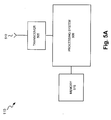
- Fig. 5A is a diagram illustrating exemplary components of repeater 110.
- repeater 110 may include a processing system 500, a transceiver 505, an antenna 510, and a memory 515.
- Processing system 500 may include a component capable of interpreting and/or executing instructions.
- processing system 500 may include, a general-purpose processor, a microprocessor, a data processor, a co-processor, a network processor, an application specific integrated circuit (ASIC), a controller, a programmable logic device, a chipset, and/or a field programmable gate array (FPGA).
- ASIC application specific integrated circuit
- Processing system 500 may control one or more other components of repeater 110.
- Processing system 500 may be capable of performing various communication-related processing (e.g., amplification, self-interference cancellation (SIC), frequency translation, etc.).
- SIC self-interference cancellation
- Transceiver 505 may include a component capable of transmitting and/or receiving information over wireless channels via antennas 510.
- Transceiver 505 may include a transmitter and a receiver.
- Transceiver 505 may be capable of performing various communication-related processing (e.g., filtering, decoding/coding, demodulation/modulation, etc.).
- Transceiver 505 may be capable of operating in FTR and OFR modes.
- Antenna 510 may include a component capable of receiving information and transmitting information via wireless channels.
- Antenna 510 may include a single system or a multi-antenna system (e.g., a MIMO antenna system).
- Antenna 510 may provide one or more forms of diversity (e.g., spatial, pattern, or polarization).
- Memory 515 may include a component capable of storing information (e.g., data and/or instructions).
- memory 515 may include a random access memory (RAM), a dynamic random access memory (DRAM), a static random access memory (SRAM), a synchronous dynamic random access memory (SDRAM), a ferroelectric random access memory (FRAM), a read only memory (ROM), a programmable read only memory (PROM), an erasable programmable read only memory (EPROM), an electrically erasable programmable read only memory (EEPROM), and/or a flash memory.
- RAM random access memory
- DRAM dynamic random access memory
- SRAM static random access memory
- SDRAM synchronous dynamic random access memory
- FRAM ferroelectric random access memory
- ROM read only memory
- PROM programmable read only memory
- EPROM erasable programmable read only memory
- EEPROM electrically erasable programmable read only memory
- repeater 110 may include fewer, additional, and/or different components than those depicted in Fig. 5A . It will be appreciated that one or more components of repeater 110 may be capable of performing one or more other tasks associated with one or more other components of repeater 110.
- Fig. 5B is a diagram illustrating an exemplary functional component capable of performing one or more operations associated with the concepts described herein.
- this exemplary functional component may be implemented in processing system 500 of repeater 110.
- the functional component may be implemented in connection with, for example, other components (e.g., transceiver 505) of repeater 110, in combination with two or more components (e.g., processing system 500, transceiver 505, memory 515) of repeater 110, and/or as an additional component(s) to those previously described in Fig. 5A .
- repeater 110 may include an FTR/OFR switcher 520.
- FTR/OFR switcher 520 may interpret an FTR/OFR mode signal.
- Repeater 110 (e.g., FTR/OFR switcher 520) may adaptively switch between and operate in FTR and OFR modes based on the FTR/OFR mode signal.
- Repeater 110 may also utilize other types of information (e.g., frequency selection information, power information, etc.) that may be included in the FRT/OFR mode signal.
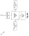
- Fig. 6A is a diagram illustrating exemplary components of UE 115.
- UE 205 may include a processing system 600, transceiver 605, antenna 610, a memory 615, an input device 620, and an output device 625.
- Processing system 600 may include a component capable of interpreting and/or executing instructions.
- processing system 600 may include a general-purpose processor, a microprocessor, a data processor, a co-processor, a network processor, an application specific integrated circuit (ASIC), a controller, a programmable logic device, a chipset, and/or a field programmable gate array (FPGA).
- ASIC application specific integrated circuit
- Processing system 600 may control one or more other components of UE 115.
- Processing system 600 may be capable of performing various communication-related processing (e.g., signal processing, channel estimation, power control, timing control, etc.), as well as other operations associated with the operation and use of UE 115.
- Transceiver 605 may include a component capable of transmitting and/or receiving information over wireless channels via antennas 610.
- Transceiver 605 may include a transmitter and a receiver.
- Transceiver 605 may include a single antenna system or a multi-antenna system (e.g., a MIMO system).
- Transceiver 605 may be capable of performing various communication-related processing (e.g., filtering, de/coding, de/modulation, signal measuring, etc.).
- Transceiver 605 may be capable of switching between and operating in FTR and OFR modes.
- Antenna 610 may include a component capable of receiving information and transmitting information via wireless channels.
- antenna 610 may include a multi-antenna system (e.g., a MIMO antenna system).
- Antenna 610 may provide one or more forms of diversity (e.g., spatial, pattern, or polarization).
- Memory 615 may include a component capable of storing information (e.g., data and/or instructions).
- memory 615 may include a random access memory (RAM), a dynamic random access memory (DRAM), a static random access memory (SRAM), a synchronous dynamic random access memory (SDRAM), a ferroelectric random access memory (FRAM), a read only memory (ROM), a programmable read only memory (PROM), an erasable programmable read only memory (EPROM), an electrically erasable programmable read only memory (EEPROM), and/or a flash memory.
- RAM random access memory
- DRAM dynamic random access memory
- SRAM static random access memory
- SDRAM synchronous dynamic random access memory
- FRAM ferroelectric random access memory
- ROM read only memory
- PROM programmable read only memory
- EPROM erasable programmable read only memory
- EEPROM electrically erasable programmable read only memory
- Input device 620 may include a component capable of receiving an input from a user and/or another device.
- input device 620 may include a keyboard, a keypad, a touchpad, a mouse, a button, a switch, a microphone, a display, a port, and/or voice recognition logic.
- Output device 625 may include a component capable of outputting information to a user and/or another device.
- output device 625 may include a display, a speaker, one or more light emitting diodes (LEDs), a vibrator, a port, and/or some other type of visual, auditory, and/or tactile output device.
- LEDs light emitting diodes
- UE 115 may include fewer, additional, and/or different components than those depicted in Fig. 6A .
- UE 115 may include a hard disk or some other type of computer-readable medium along with a corresponding drive.
- the term "computer-readable medium,” as used herein, is intended to be broadly interpreted to include, for example, a physical or a logical storage device. It will be appreciated that one or more components of UE 115 may be capable of performing one or more other tasks associated with one or more other components of UE 115.
- Fig. 6B is a diagram illustrating an exemplary functional component capable of performing one or more operations associated with the concepts described herein.
- this exemplary functional component may be implemented in processing system 600 of UE 115.
- the functional component may be implemented in connection with, for example, other components (e.g., transceiver 605) of UE 115, in combination with two or more components (e.g., processing system 600, transceiver 605, memory 615) of UE 115, and/or as an additional component(s) to those previously described in Fig. 6A .
- UE 115 may include an FTR/OFR switcher 630.
- FTR/OFR switcher 620 may interpret an FTR/OFR mode signal.
- UE 115 e.g., FTR/OFR switcher 620
- UE 115 may also utilize other types of information (e.g., frequency selection information, power information, etc.) that may be included in the FRT/OFR mode signal.
- UE 115 may perform maximum ratio combining (MRC) or interference rejection combining (IRC) when in FTR mode.
- MRC maximum ratio combining
- IRC interference rejection combining
- Fig. 6C is a diagram illustrating an exemplary implementation of UE 115, where UE 115 includes a wireless telephone.
- UE 115 may include a microphone 635 (e.g., of input device 620) for entering audio information, a speaker 640 (e.g., of output device 625) for outputting audio information, a keypad 645 (e.g., of input device 620) for entering information or selecting functions, and a display 650 (e.g., of input device 620 and/or output device 625) for outputting visual information and/or inputting information, selecting functions, etc.
- a microphone 635 e.g., of input device 620
- speaker 640 e.g., of output device 625
- a keypad 645 e.g., of input device 620
- a display 650 e.g., of input device 620 and/or output device 625
- Fig. 6C illustrates an exemplary implementation of UE 115
- UE 115 may include fewer, additional, or different exemplary components than those depicted in Fig. 6C .
- Fig. 7 is a flow diagram illustrating an exemplary process 700 for maximizing outage capacity.
- the exemplary process 700 may be performed by wireless station 105. It will be appreciated that although process 700 is being described as being performed by wireless station 105, in other implementations, process 700 may be performed by another device in environment 100, such as, for example, UE 115. Additionally, while process 700 will be described in reference to the downlink, wireless station 105 may control the adaptive switching between OFR/FTR modes for repeater 110 and UE 115 in the uplink or in both the uplink and the downlink directions. Similarly, when process 700 is performed by UE 115, UE 115 may control the adaptive switching between OFR/FTR modes for the downlink, the uplink, or both the downlink and uplink directions. In this regard, it will further be appreciated, that depending on the selected implementation, wireless station 105 and/or UE 115 may include the functional components FTR/OFR selector 220 and/or FTR/OFR switcher 630.
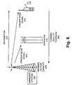
- Fig. 8 is a diagram illustrating an exemplary scenario that is consistent with process 700.
- Process 700 may begin with receiving channel quality feedback from a repeater and/or a UE (block 705).
- repeater 110 and/or UE 115 may transmit channel quality feedback 805 to wireless station 105 based on a previous communication or based on channel estimations characterized from transmitted channel estimation symbols (also known as pilot symbols, or reference signals).
- Channel quality feedback 805 may include, for example, statistical measurements of the channel or other types of data indicative of the channel characteristics.
- the statistical measurements may include, for example, mean gain, mean gain-to-noise ratio, mean SNR, mean signal-to-interference-to-noise ratio (SINR), as previously described.
- Other types of data indicative of the channel characteristics may include, for example, higher order channel statistics (e.g., variance of the SNR, variance of the SINR, etc.).
- wireless station 105 may measure and calculate channel quality feedback information.
- Outage capacities for OFR and FTR modes may be calculated based on the channel quality feedback (block 710).
- wireless station 105 may calculate outage capacities associated with the FTR mode and the OFR mode. For example, wireless station 105 may determine a mean SNR from channel quality feedback 805 to determine which of an FTR mode or an OFR mode would maximize outage capacity. For example, as illustrated in Fig. 8 , wireless station 105 may calculate a mode to maximize outage capacity 810 based on channel quality feedback 805.
- the OFR mode or the FTR mode that maximizes outage capacity may be selected (block 715).
- Wireless station 105 may select the mode of operation for repeater 110 and UE 115 that maximizes outage capacity based on the calculated outage capacities associated with the FTR mode and the OFR mode.
- the FTR/OFR mode signal that indicates the selected mode may be transmitted to the repeater and the UE (block 720).
- wireless station 105 may transmit an FTR/OFR mode signal 815 to repeater 110 and UE 115.
- FTR/OFR mode signal 815 may indicate an FTR mode or an OFR mode of operation.
- FTR/OFR mode signal 815 may include other types of communication-related decisions (e.g., which frequency band(s) to utilize, power levels, selection of intermediate devices, etc.).
- Information to the UE via the repeater may be transmitted, where the UE and the repeater are operating according to the FTR/OFR mode signal (block 725).
- wireless station 105 may transmit information 820 (e.g., data) to UE 115 via repeater 110.
- Repeater 110 and UE 115 will be operating in accordance with the FTR/OFR mode signal 815. In this regard, repeater 110 and UE 115 will be operating in the FTR mode or the OFR mode.
- process 700 may include wireless station 105 determining power levels for itself, repeater 110 (e.g., to adjust the aggregate transmit power sharing), and/or UE 115, determining which repeater to utilize when multiple repeaters are available, determining which frequency band(s) to utilize for frequency translated signal(s) in the FTR mode, and/or determining which frequency band(s) to utilize when in OFR mode.
- Wireless station 105 may make these determinations based on, for example, maximizing the outage capacity.
- wireless station 105 may measure and calculate channel quality feedback information.
- repeater 110 or some other wireless station may transmit the FTR/OFR mode signal. It will be appreciated that wireless station 105 may maximize outage capacity based on the adaptive switching between OFR and FTR modes according to various triggering events (e.g., continuous monitoring, periodic time periods, transmission/reception events, etc.).
- triggering events e.g., continuous monitoring, periodic time periods, transmission/reception events, etc.
- FIG. 9 Another exemplary process is described below, in connection with Fig. 9 , in which outage capacity is maximized.
- the exemplary process will be described based on communication system 100 depicted in Fig. 1B .
- the exemplary process may be performed in communication system 100 depicted in Fig. 1A , in which devices different than those depicted in Fig. 1B may be present.
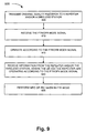
- Fig. 9 is a flow diagram illustrating an exemplary process 900 for maximizing outage capacity.
- the exemplary process 900 may be performed by UE 115. It will be appreciated that although process 900 is being described as being performed by UE 115, in other implementations, process 900 may be performed by another device in environment 100, such as, for example, wireless station 105. Additionally, while process 900 will be described in reference to the downlink, process 900 may be applicable to the uplink or both the downlink and the uplink. In this regard, depending on the selected implementation, UE 115 and/or wireless station 105 may include the functional components FTR/OFR selector 220 and/or FTR/OFR switcher 630.
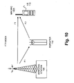
- Figs. 10A and 10B are diagrams illustrating exemplary scenarios that are consistent with process 900.
- frequency bands have been illustrated as frequency bands (F1) and (F2) in Figs. 10A and 10B .
- Process 900 may begin with transmitting channel quality information to a repeater or a wireless station (block 905).
- UE 115 may transmit channel quality information 805 to repeater 110 and/or wireless station 105 based on a previous communication.
- Channel quality feedback 805 may include, for example, statistical measurements of the channel or other types of data indicative of the channel characteristics.
- the statistical measurements may include, for example, mean gain, mean gain-to-noise ratio, mean SNR, mean signal-to-interference-to-noise ratio (SINR), as previously described.
- Other types of data indicative of the channel characteristics may include, for example, higher order channel statistics (e.g., variance of the SNR, variance of the SINR, etc.).
- wireless station 105 may measure and calculate channel quality feedback information.
- the FTR/OFR mode signal may be received (block 905).
- UE 115 may receive FTR/OFR mode signal 815, as illustrated in Fig. 8 .
- the UE may operate according to the FTR/OFR mode signal (block 915).
- FTR/OFR mode signal 815 will include the mode in which UE 115 and repeater 110 is to operate. Additionally, FTR/OFR mode signal 815 may include other communication related information (e.g., power-related, frequency-related, etc.) that may impact how UE 115 and repeater 110 operates.
- wireless station 105 may transmit information 820 (e.g., data) to UE 115 via repeater 110.
- information 820 e.g., data
- repeater 110 and UE 115 will be operating in accordance with the FTR/OFR mode signal 815.
- repeater 110 and UE 115 will be operating in the FTR mode or the OFR mode.
- UE 115 may perform MRC or IRC when in FTR mode (block 925). For example, as illustrated in Fig. 10 , depending on the mode of operation, UE 115 may perform MRC or IRC. As illustrated in Fig. 10 , when in the FTR mode, wireless station 105 may transmit on a frequency band (F1) to both repeater 110 and UE 115. However, repeater 110, when in FTR mode, shall translate frequency band (F1) to frequency band (F2) before forwarding to UE 115. In this instance, UE 115 may receive information on frequency bands (F1) and (F2).
- UE 115 may perform MRC/IRC 1005 (e.g., maximum ratio combining (MRC) or interference rejection combining (IRC)) in order to maximize the outage capacity according to the selected mode of operation.
- MRC/IRC 1005 e.g., maximum ratio combining (MRC) or interference rejection combining (IRC)
- the result of MRC/IRC 1005 may be further processed by UE 115.
- FIG. 9 illustrates an exemplary process 900, in other implementations, fewer, additional, and/or different operations may be performed. It will also be appreciated that blocks 905 through 920 represents a process that may be performed by repeater 110.
- the adaptive switching between OFR and FTR modes may be based on, in addition to maximizing outage capacity or instead of maximizing outage capacity, other robustness-related performance measures (e.g., diversity order (maximization), bit error (minimization) rate, etc.).
- robustness-related performance measures e.g., diversity order (maximization), bit error (minimization) rate, etc.
Landscapes
- Engineering & Computer Science (AREA)
- Computer Networks & Wireless Communication (AREA)
- Signal Processing (AREA)
- Quality & Reliability (AREA)
- Mobile Radio Communication Systems (AREA)
Description
- Implementations described herein relate generally to communication systems. More particularly, implementations described herein relate to a scheme for enhancing outage capacity in communication systems.
- In a communication system, such as a wireless communication system, devices may communicate with one another via an intermediary device. For example, a wireless station and user equipment (UE) may communicate via a repeater. Repeaters may be divided into two types, namely, on-frequency repeaters (OFRs) and frequency translating repeaters (FTRs). An OFR transmits a repeated signal on the same frequency, while a FTR transmits a repeated signal on a different frequency relative to the frequency used when receiving. Thus, OFRs utilize only one frequency resource while FTRs utilize two frequency resources and, as such, lose fifty-percent of those frequency resources. In this regard, the loss of such resources has a negative impact on the data rate or throughput.
- A model to evaluate performance and wireless system design is the concept of outage probability. Outage probability is a measure that, in contrast to ergodic capacity, indicates a level of robustness of a wireless link and is defined as Pr{C ≤ C 0} = ε (i.e., the outage capacity Co that the instantaneous capacity C exceeds with a probability of 1 - e). Outage capacity is typically associated with slow fading channels where the channel remains constant over a number of transmissions. In this regard, outage capacity is concerned with maintaining a constant rate during non-outage periods. In contrast, ergodic capacity is typically associated with fast fading channels where one transmission spans a number of coherence periods and equates to the ensemble average of the information rate. Existing techniques to enhance the outage capacity generally rely on a diversity method (e.g., interleaving, frequency hopping, transmit diversity, or macrodiversity).
- Existing repeaters are not designed to reduce the outage capacity experienced by a receiving station. In particular, existing repeaters do not adopt low complexity adaptive schemes that allow for outage capacity optimization and account for different signal strength levels from a repeater, as well as direct path levels from a transmitter. In other words, existing repeaters are not specifically designed to reduce the outage capacity experienced by a receiving station.
-
WO 2005/064872 A1 relates to relay supported wireless communication to enhance communication performance by using cooperative relaying. - It is an object to obviate at least some of the above disadvantages and to improve the operability of devices within a communication system.
- According to one aspect, a method may be performed by a device in a wireless network. The method may include receiving channel quality feedback information, calculating, based on the channel quality feedback information, an outage capacity associated with an on-frequency mode of operation and an outage capacity associated with a frequency-translated mode of operation, selecting the on-frequency mode of operation or the frequency-translated mode of operation that maximizes outage capacity based on the calculated outage capacities associated with the on-frequency and frequency translated modes of operation, and transmitting, to two or more other devices, a message indicating to operate in an on-frequency mode or a frequency-translated mode based on the selected on-frequency mode of operation or the frequency-translated mode of operation.
- According to another aspect, a method may be performed by a device in a wireless network. The method may include transmitting, to another device, channel quality feedback information, receiving, from the other device, a message indicating to operate in an on-frequency mode or a frequency-translated mode, based on the transmitted channel quality feedback information, and operating, by the device, in the on-frequency mode or the frequency translated mode according to the message.
- According to yet another aspect, a device in a wireless network may include one or more antennas and a processing system. The processing system may be configured to determine channel quality information, maximize an outage capacity by selecting an on-frequency mode of operation or a frequency translated mode of operation based on the channel quality information, and transmit, to two or more other devices, a message indicating to operate in an on-frequency mode or a frequency translated mode.
- According to still another aspect, a computer-readable medium may include instructions to receive channel quality information, calculate, based on the channel quality information, an outage capacity associated with an on-frequency mode of operation and an outage capacity associated with a frequency translated mode of operation, and determine which of the outage capacities associated with the on-frequency mode of operation and the frequency translated mode of operation maximizes outage capacity.
- According to yet another aspect, a system may comprise a base station to receive channel quality information that includes statistical measurements of a channel, calculate, based on the channel quality information, an outage capacity associated with an on-frequency mode of operation and an outage capacity associated with a frequency-translated mode of operation, selecting the on-frequency mode of operation or the frequency-translated mode of operation that maximizes outage capacity, and transmit a message indicating a selection of the on-frequency mode of operation or the frequency-translated mode of operation to other devices in a wireless network, and the other devices adhere to the mode of operation indicated in the message.
- Even though some embodiments have been summarized above, the claimed subject matter is defined in the attached claims 1-17.
-
-
Figs 1A and1B are diagrams illustrating devices communicating with one another via an intermediate device; -
Figs. 2A and2B are diagrams illustrating exemplary components of the wireless station depicted inFig. 1B ; -
Figs. 3 and4 are diagrams illustrating contour plots with respect to OFR and FTR modes; -
Figs. 5A and5B are diagrams illustrating exemplary components of the repeater depicted inFig. 1B ; -
Figs. 6A and6B are diagrams illustrating exemplary components of the UE depicted inFig. 1B ; -
Fig. 6C is a diagram illustrating an exemplary implementation of the UE when the UE includes a wireless telephone; -
Fig. 7 is a flow diagram illustrating an exemplary process for maximizing outage capacity; -
Fig. 8 is a diagram illustrating an exemplary scenario that is consistent with the exemplary process depicted inFig. 7 ; -
Fig. 9 is a diagram illustrating an exemplary process for maximizing outage capacity; and -
Fig. 10 is a diagram illustrating an exemplary scenario that is consistent with the exemplary process depicted inFig. 9 . - The following detailed description refers to the accompanying drawings. The same reference numbers in different drawings may identify the same or similar elements. Also, the following description does not limit the invention.
- The concepts described herein relate to a communication system. The communication system is intended to be broadly interpreted to include any type of wireless network, such as a cellular network and/or a mobile network (e.g., Global System for Mobile Communications (GSM), Long Term Evolution (LTE), Wideband Code Division Multiple Access (WCDMA), Ultra Mobile Broadband (UMB), Universal Mobile Telecommunications Systems (UMTS), Code Division Multiple Access 2000 (CDMA2000), ad hoc networks, High-Speed Packet Access (HSPA), etc.), and a non-cellular network (e.g., Wireless Fidelity (Wi-Fi), Worldwide Interoperability for Microwave Access (WiMax), etc.). In this regard, it will be appreciated that the concepts described herein are not platform dependent and may be implemented within a wide variety of communication systems.
- The communication system may include a network in which one or multiple intermediate devices (e.g., a repeater, a relay, etc.) may be employed. The terms communication system and network may be used interchangeably throughout this description.
- Embodiments described herein may provide that a device of a communication system may signal other devices to adaptively switch between OFR and FTR modes. The adaptive switching between modes may be based on one or more criteria that yield the highest outage capacity. For example, the one or more criteria may include channel quality information (e.g., mean signal-to-noise ratio (SNR)). Additionally, the device may make other types of communication-related decisions (e.g., which frequency band(s) to utilize, power levels, selection of intermediate devices, etc.). From the perspective of other devices that are in communication with the device, embodiments described herein may provide that these other devices may adaptively switch between OFR and FTR modes based on OFR/FTR mode signal (e.g., a message). Further, the other devices may perform maximum ratio combining (MRC) or interference rejection combining (IRC) when in FTR mode. Additionally, or alternatively, the other devices may provide channel quality information associated with each mode to the device.
-
Fig. 1A is a diagram illustrating anexemplary communication system 100 in which the concepts described herein may be implemented. As illustrated,communication system 100 may include adevice 105, anintermediate device 110, and adevice 115. A device (i.e.,device 105,intermediate device 110, and/or device 115) may include, for example, a UE, a gateway, a base station, a base station controller, a switch, a relay, a repeater, a bridge, a router, any combination thereof, and/or another type of device (e.g., a satellite). The device may operate atlayer 1,layer 2, and/or at a higher layer of a protocol stack. As illustrated inFig. 1A , the devices may be communicatively coupled. For example, the devices may be communicatively coupled via wireless communication links (e.g., radio, microwave, etc.). The number of devices illustrated incommunication system 100 is exemplary, and in other instances, may be different. - Since the concepts described herein are applicable to a variety of devices in
communication system 100,communication system 100 will be described based on the exemplary devices illustrated inFig. 1B. Fig. 1B illustrates an exemplary implementation in whichdevice 105 includes a wireless station,intermediate device 110 includes a repeater, anddevice 115 includes a user equipment (UE).Wireless station 105,repeater 110 andUE 115 may be communicatively coupled. -
Wireless station 105 may include a device having communication capability. The term wireless station is intended to be broadly interpreted to include, for example, a device that may communicate withUE 115 viarepeater 110. For example, a wireless station may include a base station (BS), a base station transceiver (BTS) (e.g., in a GSM communication system), an eNodeB (e.g., in a LTE communication system), a Node B (e.g., in a UMTS communication system), or some other type of device. As will be described in detail below,wireless station 105 may select, based on channel quality information, an OFR mode or an FTR mode forrepeater 110 andUE 115 to operate.Wireless station 105 may signalrepeater 110 andUE 115 indicating the mode of operation based on its selection. -
Repeater 110 may include a device having communication capability.Repeater 110 may be capable of switching between and operating in an OFR mode and an FTR mode. -
UE 115 may include a device having communication capability. For example,UE 115 may include a telephone, a computer, a personal digital assistant (PDA), a gaming device, a music playing device, a video playing device, a web browser, a personal communication system (PCS) terminal, a pervasive computing device, and/or some other type of device.UE 115 may be capable of switching between and operating in an OFR mode and a FTR mode. - Although
Fig. 1B is described aswireless station 105 andUE 115 having particular functionalities associated with the concepts described herein, in other implementations,wireless station 105 andUE 115 may be capable of performing functions that have been described as being performed byUE 115 andwireless station 105. For example,UE 115 may select, based on channel quality information, an OFR mode or an FTR mode forwireless station 105 to operate, etc. -
Fig. 2A is a diagram illustrating exemplary components ofwireless station 105. The term component is intended to be broadly interpreted to include, for example, hardware, software and hardware, firmware, software, or some other type of component and/or combination of components. As illustrated,wireless station 105 may include aprocessing system 200, atransceiver 205, anantenna 210, and amemory 215. -
Processing system 200 may include a component capable of interpreting and/or executing instructions. For example,processing system 200 may include, a general-purpose processor, a microprocessor, a data processor, a co-processor, a network processor, an application specific integrated circuit (ASIC), a controller, a programmable logic device, a chipset, and/or a field programmable gate array (FPGA).Processing system 200 may control one or more other components ofwireless station 105.Processing system 200 may be capable of performing various communication-related processing (e.g., signal processing, channel estimation, beamforming, power control, scheduling, etc.). -
Transceiver 205 may include a component capable of transmitting and/or receiving information over wireless channels viaantennas 210. For example,transceiver 205 may include a transmitter and a receiver.Transceiver 205 may be capable of performing various communication-related processing (e.g., demodulation/modulation, deinterleaving/interleaving, equalizing, filtering, decoding/coding, signal measurement, etc.).Antenna 210 may include a component capable of receiving information and transmitting information via wireless channels.Antenna 210 may include a single or a multi-antenna system (e.g., a MIMO antenna system).Antenna 210 may provide one or more forms of diversity (e.g., spatial, pattern, or polarization). -
Memory 215 may include a component capable of storing information (e.g., data and/or instructions). For example,memory 215 may include a random access memory (RAM), a dynamic random access memory (DRAM), a static random access memory (SRAM), a synchronous dynamic random access memory (SDRAM), a ferroelectric random access memory (FRAM), a read only memory (ROM), a programmable read only memory (PROM), an erasable programmable read only memory (EPROM), an electrically erasable programmable read only memory (EEPROM), and/or a flash memory. - Although
Fig. 2A illustrates exemplary components ofwireless station 105, in other implementations,wireless station 105 may include fewer, additional, and/or different components than those depicted inFig. 2A . It will be appreciated that one or more components ofwireless station 105 may be capable of performing one or more other tasks associated with one or more other components ofwireless station 105. -
Fig. 2B is a diagram illustrating an exemplary functional component capable of performing one or more operations associated with the concepts described herein. In one embodiment, this exemplary functional component may be implemented inprocessing system 200 ofwireless station 105. However, it will be appreciated that the functional component may be implemented in connection with, for example, other components (e.g., transceiver 205) ofwireless station 105, in combination with two or more components (e.g.,processing system 200,transceiver 205, memory 215) ofwireless station 105, and/or as an additional component(s) to those previously described inFig. 2A . - As illustrated in
Fig. 2B ,wireless station 105 may include an FTR/OFR selector 220. FTR/OFR selector 220 may select an FTR mode or an OFR mode forrepeater 110 andUE 115 to operate based on one or more criteria that, for example, yield the highest outage capacity, as described herein. FTR/OFR selector 220 may generate an FTR/OFR mode signal that indicates the selected mode. The FTR/OFR mode signal may also include information (e.g., information related to frequency selection, power, etc.).Wireless station 105 may transmit the FTR/OFR mode signal torepeater 110 andUE 115. - For frequency flat channels (e.g., channels having substantially the same magnitude in frequency(s)) or channels having substantially the same channel qualities (e.g., a set of Orthogonal Frequency Division Multiplexing (OFDM) subcarriers), the maximum link performance may be expressed by the Shannon capacity. Therefore, the instantaneous rate in the FTR mode may be expressed in the following manner:

- The instantaneous rate in the OFR mode may be expressed in the following manner:

- With Rayleigh fading channels from the transmitter to the receiver and the repeater to the receiver, and while having a non-fading channel from the transmitter to the repeater, Γ1 and Γ2 may be considered exponentially distributed random variables (r.v.s.). Additionally, under the Rayleigh fading assumption, Γ3 may also be considered an exponentially distributed random variable with the equivalent mean SNR of E{Γ1 + Γ2}.
- From
expressions - The mode selection process may be expressed as:


- When Rayleigh fading is assumed, the outage capacities may be fully known from the means SNRs
Γ k. Thus, expression (3) may be re-written in the following manner:
- The mean SNRs
Γ k may be obtained from channel quality information. The channel quality information may be based on measurements fromrepeater 110,UE 115, and/orwireless station 105 in the downlink or uplink. For example,UE 115 may transmit channel quality information towireless station 105. The channel quality information may include wireless station-to-UE channel quality information and wireless station-to-repeater-to-UE channel quality information. FTR/OFR selector 220 may utilize this channel quality information for determining which mode to adaptively utilize since the outage capacity is a function of the mean SNR. - It will be appreciated that although expressions (1) through (4) have been described based on the assumption of Rayleigh fading (i.e., where the channel's stochastic processes are assumed to be known), a different fading assumption may be employed. In this regard, the outage scheme may use other or additional statistical quality measurements of the channels, such as, for example, higher order statistical characterization of the channels (i.e., transmitter-to-receiver path, transmitter-to-repeater-to receiver path) in deciding whether to adaptively switch between FTR and OFR modes.
- In addition to adaptively switching between FTR/OFR modes of operation, FTR/
OFR selector 220 may also determine other operations to maximize the outage capacity. Alternatively, in other implementations, other components (e.g.,processing system 200 and/or transceiver 205) ofwireless station 105 may determine the other operations to maximize the outage capacity. For example, FTR/OFR selector 220 may select the power levels of transmission to use forwireless station 105 and/orrepeater 110, select which repeater(s) to use whenmultiple repeaters 110 are available, select the frequency band(s) to use when in FTR mode, and/or select the frequency band(s) to use when in OFR mode. The term frequency band, as used herein, is intended to be broadly interpreted to include, for example, one or more subcarriers, a frequency spectrum, one or more channels, or some other type of frequency-based segment or resource. For example, depending on the communication system, modulation scheme, communication platform, etc., the term frequency band may have a particular meaning. The selection of frequency bands when in FTR mode and/or OFR mode may include selection of frequency band(s) forwireless station 105,repeater 110, and/orUE 115. - Under the Rayleigh fading assumption,
Fig. 3 illustrates an exemplary contour plot that includes the transmitter-to-receiver mean SNR1 and the transmitter-to-repeater-to-receiver effective mean SNR2 of a five percent outage capacity in b/Hz/s for the OFR and the FTR modes, respectively.Fig. 3 further illustrates that different SNR regions are optimal for the OFR and the FTR modes, respectively. For example,Fig. 3 illustrates that the OFR mode is primarily optimal in the low SNR ranges, such as, for example,contours mean SNR 1 and themean SNR 2, it successively improves the performance for FTR relative to OFR.Fig. 4 illustrates a similar contour plot where there is a one percent outage capacity in b/Hz/s for the OFR and the FTR modes, respectively. Again,Fig. 4 illustrates that different SNR regions are optimal for the OFR and the FTR modes, respectively. Similarly,Fig. 4 illustrates that OFR mode is primarily optimal in the low SNR ranges, such as, for example,contours -
Fig. 5A is a diagram illustrating exemplary components ofrepeater 110. As illustrated,repeater 110 may include aprocessing system 500, atransceiver 505, anantenna 510, and amemory 515. -
Processing system 500 may include a component capable of interpreting and/or executing instructions. For example,processing system 500 may include, a general-purpose processor, a microprocessor, a data processor, a co-processor, a network processor, an application specific integrated circuit (ASIC), a controller, a programmable logic device, a chipset, and/or a field programmable gate array (FPGA).Processing system 500 may control one or more other components ofrepeater 110.Processing system 500 may be capable of performing various communication-related processing (e.g., amplification, self-interference cancellation (SIC), frequency translation, etc.). -
Transceiver 505 may include a component capable of transmitting and/or receiving information over wireless channels viaantennas 510.Transceiver 505 may include a transmitter and a receiver.Transceiver 505 may be capable of performing various communication-related processing (e.g., filtering, decoding/coding, demodulation/modulation, etc.).Transceiver 505 may be capable of operating in FTR and OFR modes. -
Antenna 510 may include a component capable of receiving information and transmitting information via wireless channels.Antenna 510 may include a single system or a multi-antenna system (e.g., a MIMO antenna system).Antenna 510 may provide one or more forms of diversity (e.g., spatial, pattern, or polarization). -
Memory 515 may include a component capable of storing information (e.g., data and/or instructions). For example,memory 515 may include a random access memory (RAM), a dynamic random access memory (DRAM), a static random access memory (SRAM), a synchronous dynamic random access memory (SDRAM), a ferroelectric random access memory (FRAM), a read only memory (ROM), a programmable read only memory (PROM), an erasable programmable read only memory (EPROM), an electrically erasable programmable read only memory (EEPROM), and/or a flash memory. - Although
Fig. 5A illustrates exemplary components ofrepeater 110, in other implementations,repeater 110 may include fewer, additional, and/or different components than those depicted inFig. 5A . It will be appreciated that one or more components ofrepeater 110 may be capable of performing one or more other tasks associated with one or more other components ofrepeater 110. -
Fig. 5B is a diagram illustrating an exemplary functional component capable of performing one or more operations associated with the concepts described herein. In one embodiment this exemplary functional component may be implemented inprocessing system 500 ofrepeater 110. However, it will be appreciated that the functional component may be implemented in connection with, for example, other components (e.g., transceiver 505) ofrepeater 110, in combination with two or more components (e.g.,processing system 500,transceiver 505, memory 515) ofrepeater 110, and/or as an additional component(s) to those previously described inFig. 5A . - As illustrated in
Fig. 5B ,repeater 110 may include an FTR/OFR switcher 520. FTR/OFR switcher 520 may interpret an FTR/OFR mode signal. Repeater 110 (e.g., FTR/OFR switcher 520) may adaptively switch between and operate in FTR and OFR modes based on the FTR/OFR mode signal.Repeater 110 may also utilize other types of information (e.g., frequency selection information, power information, etc.) that may be included in the FRT/OFR mode signal. -
Fig. 6A is a diagram illustrating exemplary components ofUE 115. As illustrated,UE 205 may include aprocessing system 600,transceiver 605,antenna 610, amemory 615, aninput device 620, and anoutput device 625. -
Processing system 600 may include a component capable of interpreting and/or executing instructions. For example,processing system 600 may include a general-purpose processor, a microprocessor, a data processor, a co-processor, a network processor, an application specific integrated circuit (ASIC), a controller, a programmable logic device, a chipset, and/or a field programmable gate array (FPGA).Processing system 600 may control one or more other components ofUE 115.Processing system 600 may be capable of performing various communication-related processing (e.g., signal processing, channel estimation, power control, timing control, etc.), as well as other operations associated with the operation and use ofUE 115. -
Transceiver 605 may include a component capable of transmitting and/or receiving information over wireless channels viaantennas 610.Transceiver 605 may include a transmitter and a receiver.Transceiver 605 may include a single antenna system or a multi-antenna system (e.g., a MIMO system).Transceiver 605 may be capable of performing various communication-related processing (e.g., filtering, de/coding, de/modulation, signal measuring, etc.).Transceiver 605 may be capable of switching between and operating in FTR and OFR modes. -
Antenna 610 may include a component capable of receiving information and transmitting information via wireless channels. In one implementation,antenna 610 may include a multi-antenna system (e.g., a MIMO antenna system).Antenna 610 may provide one or more forms of diversity (e.g., spatial, pattern, or polarization). -
Memory 615 may include a component capable of storing information (e.g., data and/or instructions). For example,memory 615 may include a random access memory (RAM), a dynamic random access memory (DRAM), a static random access memory (SRAM), a synchronous dynamic random access memory (SDRAM), a ferroelectric random access memory (FRAM), a read only memory (ROM), a programmable read only memory (PROM), an erasable programmable read only memory (EPROM), an electrically erasable programmable read only memory (EEPROM), and/or a flash memory. -
Input device 620 may include a component capable of receiving an input from a user and/or another device. For example,input device 620 may include a keyboard, a keypad, a touchpad, a mouse, a button, a switch, a microphone, a display, a port, and/or voice recognition logic. -
Output device 625 may include a component capable of outputting information to a user and/or another device. For example,output device 625 may include a display, a speaker, one or more light emitting diodes (LEDs), a vibrator, a port, and/or some other type of visual, auditory, and/or tactile output device. - Although
Fig. 6A illustrates exemplary components ofUE 115, in other implementations,UE 115 may include fewer, additional, and/or different components than those depicted inFig. 6A . For example,UE 115 may include a hard disk or some other type of computer-readable medium along with a corresponding drive. The term "computer-readable medium," as used herein, is intended to be broadly interpreted to include, for example, a physical or a logical storage device. It will be appreciated that one or more components ofUE 115 may be capable of performing one or more other tasks associated with one or more other components ofUE 115. -
Fig. 6B is a diagram illustrating an exemplary functional component capable of performing one or more operations associated with the concepts described herein. In one embodiment this exemplary functional component may be implemented inprocessing system 600 ofUE 115. However, it will be appreciated that the functional component may be implemented in connection with, for example, other components (e.g., transceiver 605) ofUE 115, in combination with two or more components (e.g.,processing system 600,transceiver 605, memory 615) ofUE 115, and/or as an additional component(s) to those previously described inFig. 6A . - As illustrated in
Fig. 6B ,UE 115 may include an FTR/OFR switcher 630. FTR/OFR switcher 620 may interpret an FTR/OFR mode signal. UE 115 (e.g., FTR/OFR switcher 620) may adaptively switch between and operate in FTR and OFR modes based on the FTR/OFR mode signal.UE 115 may also utilize other types of information (e.g., frequency selection information, power information, etc.) that may be included in the FRT/OFR mode signal. Additionally,UE 115 may perform maximum ratio combining (MRC) or interference rejection combining (IRC) when in FTR mode. -
Fig. 6C is a diagram illustrating an exemplary implementation ofUE 115, whereUE 115 includes a wireless telephone. As illustrated,UE 115 may include a microphone 635 (e.g., of input device 620) for entering audio information, a speaker 640 (e.g., of output device 625) for outputting audio information, a keypad 645 (e.g., of input device 620) for entering information or selecting functions, and a display 650 (e.g., ofinput device 620 and/or output device 625) for outputting visual information and/or inputting information, selecting functions, etc. - Although
Fig. 6C illustrates an exemplary implementation ofUE 115, in other implementations,UE 115 may include fewer, additional, or different exemplary components than those depicted inFig. 6C . - An exemplary process is described below, in connection with
Fig. 7 , in which outage capacity is maximized. For purposes of discussion, the exemplary process will be described based oncommunication system 100 depicted inFig. 1B . However, it will be appreciated that the exemplary process may be performed incommunication system 100 depicted inFig. 1A , in which devices different than those depicted inFig. 1B may be present. -
Fig. 7 is a flow diagram illustrating anexemplary process 700 for maximizing outage capacity. Theexemplary process 700 may be performed bywireless station 105. It will be appreciated that althoughprocess 700 is being described as being performed bywireless station 105, in other implementations,process 700 may be performed by another device inenvironment 100, such as, for example,UE 115. Additionally, whileprocess 700 will be described in reference to the downlink,wireless station 105 may control the adaptive switching between OFR/FTR modes forrepeater 110 andUE 115 in the uplink or in both the uplink and the downlink directions. Similarly, whenprocess 700 is performed byUE 115,UE 115 may control the adaptive switching between OFR/FTR modes for the downlink, the uplink, or both the downlink and uplink directions. In this regard, it will further be appreciated, that depending on the selected implementation,wireless station 105 and/orUE 115 may include the functional components FTR/OFR selector 220 and/or FTR/OFR switcher 630. - In addition to
Fig. 7 ,process 700 will be described in connection with previous figures, as well asFig. 8. Fig. 8 is a diagram illustrating an exemplary scenario that is consistent withprocess 700. -
Process 700 may begin with receiving channel quality feedback from a repeater and/or a UE (block 705). For example, as illustrated inFig. 8 ,repeater 110 and/orUE 115 may transmitchannel quality feedback 805 towireless station 105 based on a previous communication or based on channel estimations characterized from transmitted channel estimation symbols (also known as pilot symbols, or reference signals).Channel quality feedback 805 may include, for example, statistical measurements of the channel or other types of data indicative of the channel characteristics. The statistical measurements may include, for example, mean gain, mean gain-to-noise ratio, mean SNR, mean signal-to-interference-to-noise ratio (SINR), as previously described. Other types of data indicative of the channel characteristics may include, for example, higher order channel statistics (e.g., variance of the SNR, variance of the SINR, etc.). Additionally, or alternatively,wireless station 105 may measure and calculate channel quality feedback information. - Outage capacities for OFR and FTR modes may be calculated based on the channel quality feedback (block 710). As previously described above, with respect to FTR/
OFR selector 220,wireless station 105 may calculate outage capacities associated with the FTR mode and the OFR mode. For example,wireless station 105 may determine a mean SNR fromchannel quality feedback 805 to determine which of an FTR mode or an OFR mode would maximize outage capacity. For example, as illustrated inFig. 8 ,wireless station 105 may calculate a mode to maximizeoutage capacity 810 based onchannel quality feedback 805. - The OFR mode or the FTR mode that maximizes outage capacity may be selected (block 715).
Wireless station 105 may select the mode of operation forrepeater 110 andUE 115 that maximizes outage capacity based on the calculated outage capacities associated with the FTR mode and the OFR mode. - The FTR/OFR mode signal that indicates the selected mode may be transmitted to the repeater and the UE (block 720). For example, as illustrated in
Fig. 8 ,wireless station 105 may transmit an FTR/OFR mode signal 815 torepeater 110 andUE 115. FTR/OFR mode signal 815 may indicate an FTR mode or an OFR mode of operation. Additionally, as previously described, FTR/OFR mode signal 815 may include other types of communication-related decisions (e.g., which frequency band(s) to utilize, power levels, selection of intermediate devices, etc.). - Information to the UE via the repeater may be transmitted, where the UE and the repeater are operating according to the FTR/OFR mode signal (block 725). For example, as illustrated in
Fig. 8 ,wireless station 105 may transmit information 820 (e.g., data) toUE 115 viarepeater 110.Repeater 110 andUE 115 will be operating in accordance with the FTR/OFR mode signal 815. In this regard,repeater 110 andUE 115 will be operating in the FTR mode or the OFR mode. - Although
Fig. 7 illustrates anexemplary process 700, in other implementations, fewer, additional, and/or different operations may be performed. For example, as previously described,process 700 may includewireless station 105 determining power levels for itself, repeater 110 (e.g., to adjust the aggregate transmit power sharing), and/orUE 115, determining which repeater to utilize when multiple repeaters are available, determining which frequency band(s) to utilize for frequency translated signal(s) in the FTR mode, and/or determining which frequency band(s) to utilize when in OFR mode.Wireless station 105 may make these determinations based on, for example, maximizing the outage capacity. Other variations to process 700 may be contemplated. For example,wireless station 105 may measure and calculate channel quality feedback information. Additionally, or alternatively,repeater 110 or some other wireless station may transmit the FTR/OFR mode signal. It will be appreciated thatwireless station 105 may maximize outage capacity based on the adaptive switching between OFR and FTR modes according to various triggering events (e.g., continuous monitoring, periodic time periods, transmission/reception events, etc.). - Another exemplary process is described below, in connection with
Fig. 9 , in which outage capacity is maximized. For purposes of discussion, the exemplary process will be described based oncommunication system 100 depicted inFig. 1B . However, it will be appreciated that the exemplary process may be performed incommunication system 100 depicted inFig. 1A , in which devices different than those depicted inFig. 1B may be present. -
Fig. 9 is a flow diagram illustrating anexemplary process 900 for maximizing outage capacity. Theexemplary process 900 may be performed byUE 115. It will be appreciated that althoughprocess 900 is being described as being performed byUE 115, in other implementations,process 900 may be performed by another device inenvironment 100, such as, for example,wireless station 105. Additionally, whileprocess 900 will be described in reference to the downlink,process 900 may be applicable to the uplink or both the downlink and the uplink. In this regard, depending on the selected implementation,UE 115 and/orwireless station 105 may include the functional components FTR/OFR selector 220 and/or FTR/OFR switcher 630. - It will be In addition to
Fig. 9 ,process 900 will be described in connection with previous figures, as well asFigs. 10A and 10B. Figs. 10A and 10B are diagrams illustrating exemplary scenarios that are consistent withprocess 900. For purposes of illustration, frequency bands have been illustrated as frequency bands (F1) and (F2) inFigs. 10A and 10B . -
Process 900 may begin with transmitting channel quality information to a repeater or a wireless station (block 905).UE 115 may transmitchannel quality information 805 torepeater 110 and/orwireless station 105 based on a previous communication.Channel quality feedback 805 may include, for example, statistical measurements of the channel or other types of data indicative of the channel characteristics. The statistical measurements may include, for example, mean gain, mean gain-to-noise ratio, mean SNR, mean signal-to-interference-to-noise ratio (SINR), as previously described. Other types of data indicative of the channel characteristics may include, for example, higher order channel statistics (e.g., variance of the SNR, variance of the SINR, etc.). Additionally, or alternatively,wireless station 105 may measure and calculate channel quality feedback information. - The FTR/OFR mode signal may be received (block 905). For example,
UE 115 may receive FTR/OFR mode signal 815, as illustrated inFig. 8 . - The UE may operate according to the FTR/OFR mode signal (block 915). As previously described, FTR/
OFR mode signal 815 will include the mode in whichUE 115 andrepeater 110 is to operate. Additionally, FTR/OFR mode signal 815 may include other communication related information (e.g., power-related, frequency-related, etc.) that may impact howUE 115 andrepeater 110 operates. - Information from the repeater and/or the wireless station may be received, where the UE and the repeater are operating according to the FTR/OFR mode signal. For example, as illustrated in
Fig. 8 ,wireless station 105 may transmit information 820 (e.g., data) toUE 115 viarepeater 110.Repeater 110 andUE 115 will be operating in accordance with the FTR/OFR mode signal 815. In this regard,repeater 110 andUE 115 will be operating in the FTR mode or the OFR mode. - Perform MRC or IRC when in FTR mode (block 925). For example, as illustrated in
Fig. 10 , depending on the mode of operation,UE 115 may perform MRC or IRC. As illustrated inFig. 10 , when in the FTR mode,wireless station 105 may transmit on a frequency band (F1) to bothrepeater 110 andUE 115. However,repeater 110, when in FTR mode, shall translate frequency band (F1) to frequency band (F2) before forwarding toUE 115. In this instance,UE 115 may receive information on frequency bands (F1) and (F2).UE 115 may perform MRC/IRC 1005 (e.g., maximum ratio combining (MRC) or interference rejection combining (IRC)) in order to maximize the outage capacity according to the selected mode of operation. The result of MRC/IRC 1005 may be further processed byUE 115. - Although
Fig. 9 illustrates anexemplary process 900, in other implementations, fewer, additional, and/or different operations may be performed. It will also be appreciated that blocks 905 through 920 represents a process that may be performed byrepeater 110. - The foregoing description of implementations provides illustration, but is not intended to be exhaustive or to limit the implementations to the precise form disclosed. Modifications and variations are possible in light of the above teachings or may be acquired from practice of the teachings. For example, the adaptive switching between OFR and FTR modes may be based on, in addition to maximizing outage capacity or instead of maximizing outage capacity, other robustness-related performance measures (e.g., diversity order (maximization), bit error (minimization) rate, etc.).
- In addition, while series of blocks have been described with regard to the processes illustrated in
Figs. 7 and9 , the order of the blocks may be modified in other implementations. Further, non-dependent blocks may be performed in parallel. Further one or more blocks may be omitted. It will be appreciated that one or more of the processes and/or operations described herein may be implemented as a computer program. The computer program may be stored on a computer-readable medium or represented in some other type of medium (e.g., a transmission medium). - It will be apparent that aspects described herein may be implemented in many different forms of software, firmware, and hardware in the implementations illustrated in the figures. The actual software code or specialized control hardware used to implement aspects does not limit the invention. Thus, the operation and behavior of the aspects were described without reference to the specific software code - it being understood that software and control hardware can be designed to implement the aspects based on the description herein.
- It should be emphasized that the term "comprises" or "comprising" when used in the specification is taken to specify the presence of stated features, integers, steps, or components but does not preclude the presence or addition of one or more other features, integers, steps, components, or groups thereof.
- No element, act, or instruction used in the present application should be construed as critical or essential to the implementations described herein unless explicitly described as such.
- The term "may" is used throughout this application and is intended to be interpreted, for example, as "having the potential to," configured to," or "capable of," and not in a mandatory sense (e.g., as "must"). The terms "a" and "an" are intended to be interpreted to include, for example, one or more items. Where only one item is intended, the term "one" or similar language is used. Further, the phrase "based on" is intended to be interpreted to mean, for example, "based, at least in part, on," unless explicitly stated otherwise. The term "and/or" is intended to be interpreted to include any and all combinations of one or more of the associated list items.
Claims (17)
- A method performed by a first device (105, 115) in a wireless network (100), wherein the wireless network (100) comprises the first device (105, 115), a second device (105, 115) and an intermediate device (110) and wherein the second device (105, 115) and the intermediate device (110) are configured to operate in either an on-frequency mode of operation or a frequency translated mode of operation, the method being characterized by:receiving (705) channel quality feedback information, based on transmitted channel estimation symbols, from the second device (105, 115) or the intermediate device (110);calculating (710), based on the received channel quality feedback information, an outage capacity associated with the on-frequency mode of operation and the outage capacity associated with the frequency translated mode of operation;selecting (715) the on-frequency mode of operation or the frequency translated mode of operation that maximizes outage capacity based on the calculated outage capacities associated with the on-frequency and frequency translated modes of operation; andtransmitting (720), to the second device (105, 115) and the intermediate device (110), a message indicating to operate in an on-frequency mode or a frequency translated mode based on the selected on-frequency mode of operation or the frequency-translated mode of operation.
- The method of claim 1, where the first device (105, 115) includes a base station and the intermediate device (110) includes a repeater and the second device (105, 115) includes a user terminal, and the method is performed for at least one of a downlink, an uplink, or both a downlink and an uplink directions.
- The method of claim 1, where the first device (105, 115) includes a user terminal and the intermediate device (110) includes a repeater and the second device (105, 115) includes a base station, and the method is performed for at least one of a downlink, an uplink, or both a downlink and an uplink directions.
- The method of claim 1, where the calculating comprises:determining one or more of a mean signal-to-noise ratio, SNR, a mean gain, a mean gain-to-noise ratio, or a mean signal-to-interference-to-noise ratio, SINR, associated with the on-frequency mode of operation and the frequency translated mode of operation; andcalculating the outage capacity associated with the on-frequency mode of operation and the outage capacity associated with the frequency translated mode of operation based on the one or more of the mean SNR, the mean gain, the mean gain-to-noise ratio, or the mean SINR.
- The method of claim 4, where the determining the one or more of the mean SNR, the mean gain, the mean gain-to-noise ratio, or the mean SINR comprises:determining one or more the mean SNR, the mean gain, the mean gain-to-noise ratio, or the mean SINR associated with frequency bands corresponding to the on-frequency mode of operation and the frequency translated mode of operation.
- The method of claim 1, where the intermediate device (110) include a plurality of repeaters, and the method further comprises:selecting at least one of the plurality of repeaters to utilize based on a criterion to maximize outage capacity.
- The method of claim 1, where, when the frequency translated mode of operation is selected, the method further comprises:selecting one or more frequency bands to utilize based on a criterion to maximize outage capacity.
- The method of claim 1, further comprising:selecting a power level to transmit information to the second device (105, 115) and the intermediate device (110) that maximizes outage capacity according to the selected on-frequency or frequency translated mode of operation.
- The method of claim 1, where the message includes a power level to which the second device (105, 115) and the intermediate device (110) are to operate.
- A first device (105, 115), which is operable in a wireless network (100) comprising the first device (105, 115), a second device (105, 115) and an intermediate device (110) wherein the second device (105, 115) and the intermediate device (110) are configured to operate in either an on-frequency mode of operation or a frequency translated mode of operation, the first device (105, 115) being characterized by:one or more antennas (210, 610) anda processing system (200, 600) configured to:determine channel quality feedback information, the channel quality feedback being based on transmitted channel estimation symbols from the second device (105, 115) or the intermediate device (110);calculate, based on the determined channel quality feedback information, an outage capacity associated with the on-frequency mode of operation and an outage capacity associated with the frequency translated mode of operationselect the on-frequency mode of operation or the frequency translated mode of operation that maximizes an outage capacity based on the calculated outage capacities associated with the on-frequency and frequency translated modes of operation; andtransmit, to the second device (105, 115) and the intermediate device (110), a message indicating to operate in an on- frequency mode or a frequency translated mode based on the selected on-frequency mode of operation or the frequency-translated mode of operation.
- The device (105, 115) of claim 10, where the channel quality information includes one or more of a mean signal-to-noise ratio, SNR, a mean gain, a mean gain-to-noise ratio, or a mean signal-to-interference-to-noise ratio, SINR, associated with frequency bands corresponding to the on-frequency mode of operation and the frequency translated mode of operation.
- The device (105, 115) of claim 10, where the processing system is further configured to calculate the outage capacity associated with the on-frequency mode of operation and the outage capacity associated with the frequency translated mode of operation based on the one or more mean signal-to-noise ratio, SNR, mean gain, mean gain-to-noise ratio, or mean signal-to-interference-to-noise ratio, SINR.
- The device (105, 115) of claim 10, where the device (105, 115) includes a base station or a user terminal.
- The device (105, 115) of claim 10, where the processing system (200, 600) is further configured to select one or more frequency bands associated with the on-frequency mode of operation or the frequency translated mode of operation that maximizes the outage capacity.
- A computer program product stored on a computer-readable medium and including instructions that, when executed by a processor of a first device (105, 115), cause the first device (105, 115) to:perform the method steps set out in the method defined in claim 1.
- The computer program product of claim 15, further comprising instructions to calculate, based on the channel quality information, one or more mean signal-to-noise ratios, SNRs, associated with one or more frequency bands associated with the on-frequency mode of operation and the frequency translated mode of operation.
- The computer program product of claim 15, where the instructions of the computer-readable medium are executed by a base station in a wireless communication system (105).
Applications Claiming Priority (1)
| Application Number | Priority Date | Filing Date | Title |
|---|---|---|---|
| PCT/SE2008/051300 WO2010056162A1 (en) | 2008-11-12 | 2008-11-12 | Enhancing outage capacity based on adaptive mode switching between on-frequency and frequency translation |
Publications (2)
| Publication Number | Publication Date |
|---|---|
| EP2359624A1 EP2359624A1 (en) | 2011-08-24 |
| EP2359624B1 true EP2359624B1 (en) | 2016-09-21 |
Family
ID=41055346
Family Applications (1)
| Application Number | Title | Priority Date | Filing Date |
|---|---|---|---|
| EP08876285.1A Not-in-force EP2359624B1 (en) | 2008-11-12 | 2008-11-12 | Enhancing outage capacity based on adaptive mode switching between on-frequency and frequency translation |
Country Status (3)
| Country | Link |
|---|---|
| US (1) | US8472367B2 (en) |
| EP (1) | EP2359624B1 (en) |
| WO (1) | WO2010056162A1 (en) |
Families Citing this family (12)
| Publication number | Priority date | Publication date | Assignee | Title |
|---|---|---|---|---|
| IT1403065B1 (en) | 2010-12-01 | 2013-10-04 | Andrew Wireless Systems Gmbh | DISTRIBUTED ANTENNA SYSTEM FOR MIMO SIGNALS. |
| EP2351255B1 (en) * | 2008-11-26 | 2012-10-10 | Andrew Wireless Systems GmbH | Single input single output repeater for relaying a multiple input multiple output signal |
| IT1398025B1 (en) | 2010-02-12 | 2013-02-07 | Andrew Llc | DISTRIBUTED ANTENNA SYSTEM FOR MIMO COMMUNICATIONS. |
| US9078118B2 (en) * | 2010-08-27 | 2015-07-07 | Qualcomm Incorporated | Wireless communication systems and methods |
| KR20130099984A (en) | 2010-10-01 | 2013-09-06 | 앤드류 엘엘씨 | Distributed antenna system for mimo singnals |
| US20130016649A1 (en) * | 2011-07-12 | 2013-01-17 | Qualcomm Incorporated | System design for user equipment relays |
| WO2016122387A1 (en) * | 2015-01-29 | 2016-08-04 | Telefonaktiebolaget Lm Ericsson (Publ) | Channel state feedback for a wireless link having phase relaxed channels |
| US10091783B2 (en) | 2016-07-29 | 2018-10-02 | Qualcomm Incorporated | Determining frame size based on feedback |
| US11013002B2 (en) | 2017-02-06 | 2021-05-18 | Altiostar Networks, Inc. | Multi-technology aggregation architecture for long term evolution communications systems |
| BR112019016164A2 (en) * | 2017-02-06 | 2020-03-24 | Altiostar Networks, Inc. | MIMO COMMUNICATION SYSTEM OF MULTIPLE SITES WITH HYBRID BEAM FORMATION IN L1-LAYER ARCHITECTURE |
| US20180338284A1 (en) * | 2017-05-18 | 2018-11-22 | Qualcomm Incorporated | Resource utilization for reduced user equipment power consumption |
| US11936503B2 (en) * | 2020-08-04 | 2024-03-19 | Qualcomm Incorporated | Techniques for adding pilots to a forwarded signal by a repeater node |
Family Cites Families (10)
| Publication number | Priority date | Publication date | Assignee | Title |
|---|---|---|---|---|
| US20020028655A1 (en) * | 2000-07-14 | 2002-03-07 | Rosener Douglas K. | Repeater system |
| CA2323881A1 (en) * | 2000-10-18 | 2002-04-18 | Dps Wireless Inc. | Adaptive personal repeater |
| SE0303602D0 (en) * | 2003-12-30 | 2003-12-30 | Ericsson Telefon Ab L M | Method and arrangement in self-organizing cooperative network |
| EP2041888A4 (en) * | 2006-07-03 | 2013-03-20 | Ericsson Telefon Ab L M | Multi-antenna relay with self-interference cancellation |
| US8750786B2 (en) * | 2007-12-21 | 2014-06-10 | Telefonaktiebolaget Lm Ericsson (Publ) | Forwarding node in a wireless communication system |
| JP5508408B2 (en) * | 2008-06-24 | 2014-05-28 | テレフオンアクチーボラゲット エル エム エリクソン(パブル) | Frequency selective repeat method and configuration |
| JP5373895B2 (en) * | 2008-07-04 | 2013-12-18 | テレフオンアクチーボラゲット エル エム エリクソン(パブル) | Adaptive processing of filters or amplifiers by intermediate devices in multi-hop systems |
| CN102089996B (en) * | 2008-07-10 | 2016-04-20 | 艾利森电话股份有限公司 | The method and apparatus of signal is inserted by intermediate equipment |
| WO2011008148A1 (en) * | 2009-07-16 | 2011-01-20 | Telefonaktiebolaget Lm Ericsson (Publ) | Method and arrangement for repeater/relay control |
| US8458548B2 (en) * | 2009-12-22 | 2013-06-04 | Intel Corporation | Adaptive H-ARQ using outage capacity optimization |
-
2008
- 2008-11-12 US US13/128,806 patent/US8472367B2/en not_active Expired - Fee Related
- 2008-11-12 WO PCT/SE2008/051300 patent/WO2010056162A1/en not_active Ceased
- 2008-11-12 EP EP08876285.1A patent/EP2359624B1/en not_active Not-in-force
Also Published As
| Publication number | Publication date |
|---|---|
| US8472367B2 (en) | 2013-06-25 |
| US20110217921A1 (en) | 2011-09-08 |
| EP2359624A1 (en) | 2011-08-24 |
| WO2010056162A1 (en) | 2010-05-20 |
Similar Documents
| Publication | Publication Date | Title |
|---|---|---|
| EP2359624B1 (en) | Enhancing outage capacity based on adaptive mode switching between on-frequency and frequency translation | |
| US8583032B2 (en) | Communication system, communication relay apparatus, and communication relay method | |
| US9161335B2 (en) | Method and apparatus for candidate list generation for uplink V-MIMO | |
| US8768261B2 (en) | Apparatus and method for reducing interferences between base stations in wireless communication system | |
| JP4946922B2 (en) | Wireless communication device | |
| EP3018952B1 (en) | Method and apparatus for device to device communication in a wireless communication system and related apparatus using the same | |
| US8228809B1 (en) | Intelligent mode switching in communication networks | |
| EP2229743B1 (en) | Feedback with unequal error protection | |
| JP5670275B2 (en) | Wireless communication apparatus and wireless communication system | |
| US11516689B2 (en) | Control for mobility channel prediction | |
| WO2014090344A1 (en) | Backhaul communication in wireless networks | |
| KR20150134520A (en) | Apparatus for processing transmission/reception signal for interference alignment in a mu-mimo interference broadcasting channel and method thereof | |
| EP2398174B1 (en) | Communication apparatus and method for reporting reception quality | |
| US9270413B2 (en) | Frequency selective SINR regeneration | |
| US8570889B2 (en) | Filter or amplifier adaptation by an intermediate device in a multi-hop system | |
| JP4832459B2 (en) | Radio base station control apparatus and radio base station control method | |
| JP2010199870A (en) | Communication device, communication system, communication method, and antenna group selection program | |
| Kabir et al. | Performance of a cognitive cooperative relay aided downlink multi-carrier code division multiple access (MC-CDMA) system | |
| KR102382912B1 (en) | Scheduling method and apparatus of multi-antenna communication system, and method and apparatus for feeding-back channel quality indicator | |
| EP3301839B1 (en) | Method and device for providing cqi reports | |
| JP7787473B2 (en) | Wireless communication device, communication system, wireless communication method, and program | |
| CN111194040A (en) | Method and device for reporting beam | |
| Wang et al. | Throughput-based rate and power control for cognitive radio networks with receive diversity and error control | |
| Chu et al. | Cognitive MIMO AF relay network with TAS/MRC under peak interference power constraint | |
| WO2023274489A1 (en) | Ap-based action triggering in a distributed massive mimo system |
Legal Events
| Date | Code | Title | Description |
|---|---|---|---|
| PUAI | Public reference made under article 153(3) epc to a published international application that has entered the european phase |
Free format text: ORIGINAL CODE: 0009012 |
|
| 17P | Request for examination filed |
Effective date: 20110322 |
|
| AK | Designated contracting states |
Kind code of ref document: A1 Designated state(s): AT BE BG CH CY CZ DE DK EE ES FI FR GB GR HR HU IE IS IT LI LT LU LV MC MT NL NO PL PT RO SE SI SK TR |
|
| DAX | Request for extension of the european patent (deleted) | ||
| 17Q | First examination report despatched |
Effective date: 20120712 |
|
| GRAP | Despatch of communication of intention to grant a patent |
Free format text: ORIGINAL CODE: EPIDOSNIGR1 |
|
| INTG | Intention to grant announced |
Effective date: 20160425 |
|
| GRAS | Grant fee paid |
Free format text: ORIGINAL CODE: EPIDOSNIGR3 |
|
| GRAA | (expected) grant |
Free format text: ORIGINAL CODE: 0009210 |
|
| AK | Designated contracting states |
Kind code of ref document: B1 Designated state(s): AT BE BG CH CY CZ DE DK EE ES FI FR GB GR HR HU IE IS IT LI LT LU LV MC MT NL NO PL PT RO SE SI SK TR |
|
| REG | Reference to a national code |
Ref country code: GB Ref legal event code: FG4D |
|
| REG | Reference to a national code |
Ref country code: CH Ref legal event code: EP |
|
| REG | Reference to a national code |
Ref country code: AT Ref legal event code: REF Ref document number: 831908 Country of ref document: AT Kind code of ref document: T Effective date: 20161015 |
|
| REG | Reference to a national code |
Ref country code: IE Ref legal event code: FG4D |
|
| REG | Reference to a national code |
Ref country code: DE Ref legal event code: R096 Ref document number: 602008046441 Country of ref document: DE |
|
| REG | Reference to a national code |
Ref country code: LT Ref legal event code: MG4D Ref country code: NL Ref legal event code: MP Effective date: 20160921 |
|
| PG25 | Lapsed in a contracting state [announced via postgrant information from national office to epo] |
Ref country code: LT Free format text: LAPSE BECAUSE OF FAILURE TO SUBMIT A TRANSLATION OF THE DESCRIPTION OR TO PAY THE FEE WITHIN THE PRESCRIBED TIME-LIMIT Effective date: 20160921 Ref country code: NO Free format text: LAPSE BECAUSE OF FAILURE TO SUBMIT A TRANSLATION OF THE DESCRIPTION OR TO PAY THE FEE WITHIN THE PRESCRIBED TIME-LIMIT Effective date: 20161221 Ref country code: FI Free format text: LAPSE BECAUSE OF FAILURE TO SUBMIT A TRANSLATION OF THE DESCRIPTION OR TO PAY THE FEE WITHIN THE PRESCRIBED TIME-LIMIT Effective date: 20160921 |
|
| REG | Reference to a national code |
Ref country code: AT Ref legal event code: MK05 Ref document number: 831908 Country of ref document: AT Kind code of ref document: T Effective date: 20160921 |
|
| PG25 | Lapsed in a contracting state [announced via postgrant information from national office to epo] |
Ref country code: LV Free format text: LAPSE BECAUSE OF FAILURE TO SUBMIT A TRANSLATION OF THE DESCRIPTION OR TO PAY THE FEE WITHIN THE PRESCRIBED TIME-LIMIT Effective date: 20160921 Ref country code: NL Free format text: LAPSE BECAUSE OF FAILURE TO SUBMIT A TRANSLATION OF THE DESCRIPTION OR TO PAY THE FEE WITHIN THE PRESCRIBED TIME-LIMIT Effective date: 20160921 Ref country code: SE Free format text: LAPSE BECAUSE OF FAILURE TO SUBMIT A TRANSLATION OF THE DESCRIPTION OR TO PAY THE FEE WITHIN THE PRESCRIBED TIME-LIMIT Effective date: 20160921 Ref country code: GR Free format text: LAPSE BECAUSE OF FAILURE TO SUBMIT A TRANSLATION OF THE DESCRIPTION OR TO PAY THE FEE WITHIN THE PRESCRIBED TIME-LIMIT Effective date: 20161222 Ref country code: BE Free format text: LAPSE BECAUSE OF NON-PAYMENT OF DUE FEES Effective date: 20161130 |
|
| PG25 | Lapsed in a contracting state [announced via postgrant information from national office to epo] |
Ref country code: RO Free format text: LAPSE BECAUSE OF FAILURE TO SUBMIT A TRANSLATION OF THE DESCRIPTION OR TO PAY THE FEE WITHIN THE PRESCRIBED TIME-LIMIT Effective date: 20160921 Ref country code: EE Free format text: LAPSE BECAUSE OF FAILURE TO SUBMIT A TRANSLATION OF THE DESCRIPTION OR TO PAY THE FEE WITHIN THE PRESCRIBED TIME-LIMIT Effective date: 20160921 |
|
| PG25 | Lapsed in a contracting state [announced via postgrant information from national office to epo] |
Ref country code: PT Free format text: LAPSE BECAUSE OF FAILURE TO SUBMIT A TRANSLATION OF THE DESCRIPTION OR TO PAY THE FEE WITHIN THE PRESCRIBED TIME-LIMIT Effective date: 20170123 Ref country code: SK Free format text: LAPSE BECAUSE OF FAILURE TO SUBMIT A TRANSLATION OF THE DESCRIPTION OR TO PAY THE FEE WITHIN THE PRESCRIBED TIME-LIMIT Effective date: 20160921 Ref country code: BG Free format text: LAPSE BECAUSE OF FAILURE TO SUBMIT A TRANSLATION OF THE DESCRIPTION OR TO PAY THE FEE WITHIN THE PRESCRIBED TIME-LIMIT Effective date: 20161221 Ref country code: PL Free format text: LAPSE BECAUSE OF FAILURE TO SUBMIT A TRANSLATION OF THE DESCRIPTION OR TO PAY THE FEE WITHIN THE PRESCRIBED TIME-LIMIT Effective date: 20160921 Ref country code: CZ Free format text: LAPSE BECAUSE OF FAILURE TO SUBMIT A TRANSLATION OF THE DESCRIPTION OR TO PAY THE FEE WITHIN THE PRESCRIBED TIME-LIMIT Effective date: 20160921 Ref country code: AT Free format text: LAPSE BECAUSE OF FAILURE TO SUBMIT A TRANSLATION OF THE DESCRIPTION OR TO PAY THE FEE WITHIN THE PRESCRIBED TIME-LIMIT Effective date: 20160921 Ref country code: ES Free format text: LAPSE BECAUSE OF FAILURE TO SUBMIT A TRANSLATION OF THE DESCRIPTION OR TO PAY THE FEE WITHIN THE PRESCRIBED TIME-LIMIT Effective date: 20160921 Ref country code: IS Free format text: LAPSE BECAUSE OF FAILURE TO SUBMIT A TRANSLATION OF THE DESCRIPTION OR TO PAY THE FEE WITHIN THE PRESCRIBED TIME-LIMIT Effective date: 20170121 Ref country code: BE Free format text: LAPSE BECAUSE OF FAILURE TO SUBMIT A TRANSLATION OF THE DESCRIPTION OR TO PAY THE FEE WITHIN THE PRESCRIBED TIME-LIMIT Effective date: 20160921 |
|
| REG | Reference to a national code |
Ref country code: DE Ref legal event code: R097 Ref document number: 602008046441 Country of ref document: DE |
|
| PG25 | Lapsed in a contracting state [announced via postgrant information from national office to epo] |
Ref country code: IT Free format text: LAPSE BECAUSE OF FAILURE TO SUBMIT A TRANSLATION OF THE DESCRIPTION OR TO PAY THE FEE WITHIN THE PRESCRIBED TIME-LIMIT Effective date: 20160921 |
|
| REG | Reference to a national code |
Ref country code: CH Ref legal event code: PL |
|
| PLBE | No opposition filed within time limit |
Free format text: ORIGINAL CODE: 0009261 |
|
| STAA | Information on the status of an ep patent application or granted ep patent |
Free format text: STATUS: NO OPPOSITION FILED WITHIN TIME LIMIT |
|
| PG25 | Lapsed in a contracting state [announced via postgrant information from national office to epo] |
Ref country code: LI Free format text: LAPSE BECAUSE OF NON-PAYMENT OF DUE FEES Effective date: 20161130 Ref country code: CH Free format text: LAPSE BECAUSE OF NON-PAYMENT OF DUE FEES Effective date: 20161130 Ref country code: DK Free format text: LAPSE BECAUSE OF FAILURE TO SUBMIT A TRANSLATION OF THE DESCRIPTION OR TO PAY THE FEE WITHIN THE PRESCRIBED TIME-LIMIT Effective date: 20160921 |
|
| REG | Reference to a national code |
Ref country code: IE Ref legal event code: MM4A |
|
| REG | Reference to a national code |
Ref country code: FR Ref legal event code: ST Effective date: 20170731 |
|
| 26N | No opposition filed |
Effective date: 20170622 |
|
| PG25 | Lapsed in a contracting state [announced via postgrant information from national office to epo] |
Ref country code: LU Free format text: LAPSE BECAUSE OF NON-PAYMENT OF DUE FEES Effective date: 20161130 |
|
| PG25 | Lapsed in a contracting state [announced via postgrant information from national office to epo] |
Ref country code: FR Free format text: LAPSE BECAUSE OF NON-PAYMENT OF DUE FEES Effective date: 20161130 |
|
| PG25 | Lapsed in a contracting state [announced via postgrant information from national office to epo] |
Ref country code: IE Free format text: LAPSE BECAUSE OF NON-PAYMENT OF DUE FEES Effective date: 20161112 Ref country code: SI Free format text: LAPSE BECAUSE OF FAILURE TO SUBMIT A TRANSLATION OF THE DESCRIPTION OR TO PAY THE FEE WITHIN THE PRESCRIBED TIME-LIMIT Effective date: 20160921 |
|
| PG25 | Lapsed in a contracting state [announced via postgrant information from national office to epo] |
Ref country code: CY Free format text: LAPSE BECAUSE OF FAILURE TO SUBMIT A TRANSLATION OF THE DESCRIPTION OR TO PAY THE FEE WITHIN THE PRESCRIBED TIME-LIMIT Effective date: 20160921 Ref country code: HU Free format text: LAPSE BECAUSE OF FAILURE TO SUBMIT A TRANSLATION OF THE DESCRIPTION OR TO PAY THE FEE WITHIN THE PRESCRIBED TIME-LIMIT; INVALID AB INITIO Effective date: 20081112 |
|
| PG25 | Lapsed in a contracting state [announced via postgrant information from national office to epo] |
Ref country code: TR Free format text: LAPSE BECAUSE OF FAILURE TO SUBMIT A TRANSLATION OF THE DESCRIPTION OR TO PAY THE FEE WITHIN THE PRESCRIBED TIME-LIMIT Effective date: 20160921 Ref country code: MC Free format text: LAPSE BECAUSE OF FAILURE TO SUBMIT A TRANSLATION OF THE DESCRIPTION OR TO PAY THE FEE WITHIN THE PRESCRIBED TIME-LIMIT Effective date: 20160921 Ref country code: HR Free format text: LAPSE BECAUSE OF FAILURE TO SUBMIT A TRANSLATION OF THE DESCRIPTION OR TO PAY THE FEE WITHIN THE PRESCRIBED TIME-LIMIT Effective date: 20160921 |
|
| PG25 | Lapsed in a contracting state [announced via postgrant information from national office to epo] |
Ref country code: MT Free format text: LAPSE BECAUSE OF NON-PAYMENT OF DUE FEES Effective date: 20161112 |
|
| PGFP | Annual fee paid to national office [announced via postgrant information from national office to epo] |
Ref country code: DE Payment date: 20181128 Year of fee payment: 11 |
|
| PGFP | Annual fee paid to national office [announced via postgrant information from national office to epo] |
Ref country code: GB Payment date: 20181127 Year of fee payment: 11 |
|
| REG | Reference to a national code |
Ref country code: DE Ref legal event code: R119 Ref document number: 602008046441 Country of ref document: DE |
|
| GBPC | Gb: european patent ceased through non-payment of renewal fee |
Effective date: 20191112 |
|
| PG25 | Lapsed in a contracting state [announced via postgrant information from national office to epo] |
Ref country code: GB Free format text: LAPSE BECAUSE OF NON-PAYMENT OF DUE FEES Effective date: 20191112 Ref country code: DE Free format text: LAPSE BECAUSE OF NON-PAYMENT OF DUE FEES Effective date: 20200603 |