EP2358607B1 - Container for liquid soap or the like - Google Patents
Container for liquid soap or the like Download PDFInfo
- Publication number
- EP2358607B1 EP2358607B1 EP09760261.9A EP09760261A EP2358607B1 EP 2358607 B1 EP2358607 B1 EP 2358607B1 EP 09760261 A EP09760261 A EP 09760261A EP 2358607 B1 EP2358607 B1 EP 2358607B1
- Authority
- EP
- European Patent Office
- Prior art keywords
- container
- cap
- liquid
- conical body
- relief valve
- Prior art date
- Legal status (The legal status is an assumption and is not a legal conclusion. Google has not performed a legal analysis and makes no representation as to the accuracy of the status listed.)
- Active
Links
- 239000007788 liquid Substances 0.000 title claims description 32
- 239000000344 soap Substances 0.000 title claims description 4
- 239000003795 chemical substances by application Substances 0.000 claims description 2
- 239000006071 cream Substances 0.000 claims description 2
- 238000005187 foaming Methods 0.000 claims description 2
- 239000008269 hand cream Substances 0.000 claims description 2
- 239000006210 lotion Substances 0.000 claims description 2
- 239000002453 shampoo Substances 0.000 claims description 2
- 239000008257 shaving cream Substances 0.000 claims description 2
- 239000000606 toothpaste Substances 0.000 claims description 2
- 229940034610 toothpaste Drugs 0.000 claims description 2
- 238000005406 washing Methods 0.000 claims description 2
- 230000004888 barrier function Effects 0.000 description 4
- 238000000465 moulding Methods 0.000 description 4
- 239000000463 material Substances 0.000 description 3
- 239000013536 elastomeric material Substances 0.000 description 2
- 239000012530 fluid Substances 0.000 description 2
- LFQSCWFLJHTTHZ-UHFFFAOYSA-N Ethanol Chemical compound CCO LFQSCWFLJHTTHZ-UHFFFAOYSA-N 0.000 description 1
- 239000000853 adhesive Substances 0.000 description 1
- 230000001070 adhesive effect Effects 0.000 description 1
- 238000000071 blow moulding Methods 0.000 description 1
- 238000004891 communication Methods 0.000 description 1
- 230000002452 interceptive effect Effects 0.000 description 1
- 239000012263 liquid product Substances 0.000 description 1
- 238000004519 manufacturing process Methods 0.000 description 1
- 238000000034 method Methods 0.000 description 1
- 239000004033 plastic Substances 0.000 description 1
- 229920003023 plastic Polymers 0.000 description 1
- 239000000047 product Substances 0.000 description 1
- 239000012858 resilient material Substances 0.000 description 1
- 238000007789 sealing Methods 0.000 description 1
- 238000000926 separation method Methods 0.000 description 1
- 239000007787 solid Substances 0.000 description 1
- XLYOFNOQVPJJNP-UHFFFAOYSA-N water Substances O XLYOFNOQVPJJNP-UHFFFAOYSA-N 0.000 description 1
Images


Classifications
-
- B—PERFORMING OPERATIONS; TRANSPORTING
- B65—CONVEYING; PACKING; STORING; HANDLING THIN OR FILAMENTARY MATERIAL
- B65D—CONTAINERS FOR STORAGE OR TRANSPORT OF ARTICLES OR MATERIALS, e.g. BAGS, BARRELS, BOTTLES, BOXES, CANS, CARTONS, CRATES, DRUMS, JARS, TANKS, HOPPERS, FORWARDING CONTAINERS; ACCESSORIES, CLOSURES, OR FITTINGS THEREFOR; PACKAGING ELEMENTS; PACKAGES
- B65D51/00—Closures not otherwise provided for
- B65D51/16—Closures not otherwise provided for with means for venting air or gas
- B65D51/1633—Closures not otherwise provided for with means for venting air or gas whereby venting occurs by automatic opening of the closure, container or other element
- B65D51/1644—Closures not otherwise provided for with means for venting air or gas whereby venting occurs by automatic opening of the closure, container or other element the element being a valve
- B65D51/165—Closures not otherwise provided for with means for venting air or gas whereby venting occurs by automatic opening of the closure, container or other element the element being a valve formed by a slit or narrow opening
-
- A—HUMAN NECESSITIES
- A47—FURNITURE; DOMESTIC ARTICLES OR APPLIANCES; COFFEE MILLS; SPICE MILLS; SUCTION CLEANERS IN GENERAL
- A47K—SANITARY EQUIPMENT NOT OTHERWISE PROVIDED FOR; TOILET ACCESSORIES
- A47K5/00—Holders or dispensers for soap, toothpaste, or the like
- A47K5/06—Dispensers for soap
- A47K5/12—Dispensers for soap for liquid or pasty soap
-
- F—MECHANICAL ENGINEERING; LIGHTING; HEATING; WEAPONS; BLASTING
- F16—ENGINEERING ELEMENTS AND UNITS; GENERAL MEASURES FOR PRODUCING AND MAINTAINING EFFECTIVE FUNCTIONING OF MACHINES OR INSTALLATIONS; THERMAL INSULATION IN GENERAL
- F16K—VALVES; TAPS; COCKS; ACTUATING-FLOATS; DEVICES FOR VENTING OR AERATING
- F16K15/00—Check valves
- F16K15/14—Check valves with flexible valve members
- F16K15/144—Check valves with flexible valve members the closure elements being fixed along all or a part of their periphery
- F16K15/145—Check valves with flexible valve members the closure elements being fixed along all or a part of their periphery the closure elements being shaped as a solids of revolution, e.g. cylindrical or conical
-
- F—MECHANICAL ENGINEERING; LIGHTING; HEATING; WEAPONS; BLASTING
- F16—ENGINEERING ELEMENTS AND UNITS; GENERAL MEASURES FOR PRODUCING AND MAINTAINING EFFECTIVE FUNCTIONING OF MACHINES OR INSTALLATIONS; THERMAL INSULATION IN GENERAL
- F16K—VALVES; TAPS; COCKS; ACTUATING-FLOATS; DEVICES FOR VENTING OR AERATING
- F16K17/00—Safety valves; Equalising valves, e.g. pressure relief valves
- F16K17/02—Safety valves; Equalising valves, e.g. pressure relief valves opening on surplus pressure on one side; closing on insufficient pressure on one side
- F16K17/04—Safety valves; Equalising valves, e.g. pressure relief valves opening on surplus pressure on one side; closing on insufficient pressure on one side spring-loaded
- F16K17/08—Safety valves; Equalising valves, e.g. pressure relief valves opening on surplus pressure on one side; closing on insufficient pressure on one side spring-loaded with special arrangements for providing a large discharge passage
- F16K17/085—Safety valves; Equalising valves, e.g. pressure relief valves opening on surplus pressure on one side; closing on insufficient pressure on one side spring-loaded with special arrangements for providing a large discharge passage with diaphragm
-
- F—MECHANICAL ENGINEERING; LIGHTING; HEATING; WEAPONS; BLASTING
- F16—ENGINEERING ELEMENTS AND UNITS; GENERAL MEASURES FOR PRODUCING AND MAINTAINING EFFECTIVE FUNCTIONING OF MACHINES OR INSTALLATIONS; THERMAL INSULATION IN GENERAL
- F16K—VALVES; TAPS; COCKS; ACTUATING-FLOATS; DEVICES FOR VENTING OR AERATING
- F16K17/00—Safety valves; Equalising valves, e.g. pressure relief valves
- F16K17/02—Safety valves; Equalising valves, e.g. pressure relief valves opening on surplus pressure on one side; closing on insufficient pressure on one side
- F16K17/04—Safety valves; Equalising valves, e.g. pressure relief valves opening on surplus pressure on one side; closing on insufficient pressure on one side spring-loaded
- F16K17/08—Safety valves; Equalising valves, e.g. pressure relief valves opening on surplus pressure on one side; closing on insufficient pressure on one side spring-loaded with special arrangements for providing a large discharge passage
- F16K17/087—Safety valves; Equalising valves, e.g. pressure relief valves opening on surplus pressure on one side; closing on insufficient pressure on one side spring-loaded with special arrangements for providing a large discharge passage with bellows
-
- F—MECHANICAL ENGINEERING; LIGHTING; HEATING; WEAPONS; BLASTING
- F16—ENGINEERING ELEMENTS AND UNITS; GENERAL MEASURES FOR PRODUCING AND MAINTAINING EFFECTIVE FUNCTIONING OF MACHINES OR INSTALLATIONS; THERMAL INSULATION IN GENERAL
- F16K—VALVES; TAPS; COCKS; ACTUATING-FLOATS; DEVICES FOR VENTING OR AERATING
- F16K7/00—Diaphragm valves or cut-off apparatus, e.g. with a member deformed, but not moved bodily, to close the passage ; Pinch valves
- F16K7/02—Diaphragm valves or cut-off apparatus, e.g. with a member deformed, but not moved bodily, to close the passage ; Pinch valves with tubular diaphragm
- F16K7/04—Diaphragm valves or cut-off apparatus, e.g. with a member deformed, but not moved bodily, to close the passage ; Pinch valves with tubular diaphragm constrictable by external radial force
- F16K7/07—Diaphragm valves or cut-off apparatus, e.g. with a member deformed, but not moved bodily, to close the passage ; Pinch valves with tubular diaphragm constrictable by external radial force by means of fluid pressure
-
- B—PERFORMING OPERATIONS; TRANSPORTING
- B65—CONVEYING; PACKING; STORING; HANDLING THIN OR FILAMENTARY MATERIAL
- B65D—CONTAINERS FOR STORAGE OR TRANSPORT OF ARTICLES OR MATERIALS, e.g. BAGS, BARRELS, BOTTLES, BOXES, CANS, CARTONS, CRATES, DRUMS, JARS, TANKS, HOPPERS, FORWARDING CONTAINERS; ACCESSORIES, CLOSURES, OR FITTINGS THEREFOR; PACKAGING ELEMENTS; PACKAGES
- B65D2205/00—Venting means
-
- F—MECHANICAL ENGINEERING; LIGHTING; HEATING; WEAPONS; BLASTING
- F16—ENGINEERING ELEMENTS AND UNITS; GENERAL MEASURES FOR PRODUCING AND MAINTAINING EFFECTIVE FUNCTIONING OF MACHINES OR INSTALLATIONS; THERMAL INSULATION IN GENERAL
- F16K—VALVES; TAPS; COCKS; ACTUATING-FLOATS; DEVICES FOR VENTING OR AERATING
- F16K15/00—Check valves
- F16K15/14—Check valves with flexible valve members
- F16K15/144—Check valves with flexible valve members the closure elements being fixed along all or a part of their periphery
-
- Y—GENERAL TAGGING OF NEW TECHNOLOGICAL DEVELOPMENTS; GENERAL TAGGING OF CROSS-SECTIONAL TECHNOLOGIES SPANNING OVER SEVERAL SECTIONS OF THE IPC; TECHNICAL SUBJECTS COVERED BY FORMER USPC CROSS-REFERENCE ART COLLECTIONS [XRACs] AND DIGESTS
- Y10—TECHNICAL SUBJECTS COVERED BY FORMER USPC
- Y10T—TECHNICAL SUBJECTS COVERED BY FORMER US CLASSIFICATION
- Y10T137/00—Fluid handling
- Y10T137/7722—Line condition change responsive valves
- Y10T137/7837—Direct response valves [i.e., check valve type]
- Y10T137/7897—Vacuum relief type
Definitions
- the present invention is directed to a container having a relief valve.
- the invention is directed to a dispenser having a relief valve which dispenses liquid soap or the like.
- a dispenser having a relief valve which dispenses liquid soap or the like.
- the pressure within the container drops. Once the pressure drops below a certain level, air would be drawn in through the liquid outlet, thereby interfering with the outlet flow.
- a separate pressure relief valve is provided to allow air into the container once the pressure within the container drops below a certain level.
- the present invention aims to provide a container having a pressure relief valve that can operate well in the cap of a container when the container is in an inverted configuration with the cap lowermost.
- the valve should be simple in structure and suited to mass production.
- a container having a cap and a bottle, the container having an outlet in the cap and being arranged to dispense liquid from the container when in an inverted configuration; characterised in having a pressure relief valve in the cap, the pressure relief valve comprising a substantially conical body extending into the container, and tapering inwardly away from an external wall of the container, at least one air inlet passage through the substantially conical body; and a flexible diaphragm extending over the conical body, being attached at its outer periphery around the substantially conical body and having a central opening surrounding the substantially conical body above the air inlet passage so as to seal the air inlet passage until the pressure within the container falls below a predetermined level, wherein the diaphragm comprises a resilient lip that seals against the conical body.
- the substantially conical body with the air inlet passage can simply be part of the molding of the underlying container. All that is then required is the flexible diaphragm which can readily be fitted in place.
- the conical body supports the diaphragm, and the weight of the liquid in the container only serves to enhance the seal under normal circumstances. Because of the underlying support, the diaphragm material can be made very thin as the material itself does not need to support the weight of the liquid without buckling. This thin diaphragm layer is then readily displaceable by the incoming air when the pressure within the container drops.
- the diaphragm may seal against the wall of the conical body itself. In this case, if the angle of inclination of the diaphragm is less than the angle of inclination of the conical body, this creates a natural biasing force to hold the diaphragm on the body.
- a cylindrical post is upstanding from the conical body.
- the liquid container has an outlet valve to control the flow of liquid out of the container.
- the flexible diaphragm is preferably integral with the outlet valve. If the outlet valve is resiliently biased by biasing elements these are also preferably integral with the diaphragm and the outlet valve. This simplifies the structure of the relief valve as the flexible diaphragm can effectively be molded into an existing component rather than being a separate component in its own right.
- the relief valve is designed to prevent air from entering through a liquid outlet, as this disrupts the liquid flow and does not dispense the desired dose.
- a refill unit for dispensing a liquid designed to be used in a inverted configuration, with the outlet at its lowermost end, will typically comprise a bottle forming the main body of the unit with a cap at its lowermost end. In such a unit, it is desirable to place the outlet and the relief valve in the cap.. This allows the bottle to be formed as a simple molding such as a blow molding, while the cap can be a more complex molding comprising a number of pieces. However, this brings the relief valve into close proximity to the outlet thereby reintroducing the possibility of incoming air being entrained in the outgoing liquid and disrupting the flow. This imposes limitations on the placing of the outlet and relief valve and also means that the diameter of the cap must be reasonably large in order to provide adequate separation between the outlet and the relief valve.
- the shroud prevents there being a direct path for the incoming air to the liquid outlet, thereby allowing the relief valve to be positioned closer to the outlet valve. This allows greater flexibility of the positioning of the relief valve and the outlet, and allows the cap to be reduced in size.
- each pressure relief valve is associated with a shroud in the form of a wall surrounding at least the side of the pressure relief valve facing the outlet and extending to a location above the valve seat when the unit is in its usual orientation with the cap at the lowermost end.
- the pressure relief valve comprises a resilient component which is deformable when the internal pressure drops below the certain level, the resilient component being preferably attached to the cap by being sandwiched between the cap and a fixing plate, wherein the shroud is provided in the fixing plate.
- the resilient component is preferably integral with the outlet valve.
- the outlet valve may be biased by biasing elements, which may also be integral with the outlet valve and resilient component.
- the dispenser is a hands-free dispenser which is generally suitable for domestic use.
- the dispenser is primarily intended to dispense liquid soap, but may also be used to dispense other liquid or semi-liquid products (ideally with a viscosity greater than water), such as hand cream, body lotion, moisturiser, face cream, shampoo, shower gel, foaming hand wash, shaving cream, washing up liquid, toothpaste or a sanitising agent such as alcohol gel.
- the dispenser comprises two main parts, namely a refill 1 and a base unit 2.
- the refill 1 provides a reservoir of liquid to be dispensed and is fitted to the base unit 2 as set out below.
- the base has an interface 3 into which liquid is dispensed from the refill unit.
- the interface 3 is in fluid communication with a dispensing tube 4.
- a pump 5 is selectively operable to pump a metered dose of the liquid along dispensing tube 4 and out of dispensing head 6.
- the base has an infrared transmitter 7A which transmits an infrared beam through a window 8 to a receiver 7B to sense the presence of a user's hands in the vicinity of the dispenser.
- Control circuitry reacts to a signal from the proximity sensor to activate the pump.
- the illustrated sensor is a break beam sensor, but may also be a reflective sensor. Although an infrared sensor is shown, any known proximity sensor such as a capacitive sensor may be used.
- the device may be mains powered or battery powered. Alternatively, it may be a manually operated pump device in which a user pushes a lever to displace the product.
- the base unit 2 comprises a cowling 10 which forms a cup-shaped housing surrounding a significant portion of the refill to protect and support it.
- a spigot 11 projects through the base of the cowling 10 and is sealed to the cowling 10 by an O-ring seal 12.
- the spigot has a plurality of castellations 13 in its top surface.
- a second O-ring seal 14 surrounds the spigot 11 beneath the castellations 13.
- the refill 1 comprises a bottle 20 to which a cap 21 is fixed.
- the bottle 20 has a neck 22 which fits over and seals with an annular flange 23 within the cap 21.
- the cap 21 has an upwardly depending skirt 24 (when in the inverted orientation shown in the drawings) which forms the outer surface of the cap.
- Working inwardly from the skirt 24, the next feature of the cap is an outer annular wall 25 which is generally co-axial with the skirt 24.
- the outer annular wall 25 consists of a pair of retaining members 26 and a pair of support members 27 which alternate with one another and each extend for approximately a quarter of the circle as shown in Figs. 5 , 6 , 8 and 10 .
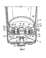
- the profile of the support members 27 is as shown in Fig. 2 . These members extend directly up from the lower wall of the cap, are parallel sided and have an inclined upper surface 28.
- the profile of the retaining members 26 is shown in Figs. 7 and 9 . Unlike the support members 27, these are not fixed to the wall of the cap. Instead, they are fixed at either end to the support members 27 by frangible members 29 as best shown in Figs. 6 and 8 .
- the retaining members 26 are parallel sided and have an inclined upper surface 35 as shown in Figs. 7 and 9 .
- the neck 22 of the bottle has an inclined outer surface 36 which is complimentary to the inclined surfaces 28 and 35 of the annular wall 25. Behind the inclined outer surface 36 is a shoulder 37 which faces the main body of the bottle 20. This inclined outer surface 36 and shoulder 37 is only present in the vicinity of the retaining members 26 and not in the vicinity of the support members 27. Adjacent to the support members 27, the neck 22 has a parallel sided configuration as shown in Fig. 2 .
- the bottle 20 In order to insert the bottle 20 into the cap 21, the bottle 20 is pushed down with its neck fitting over the annular flange 23.
- the inclined outer surface 36 of the bottle co-operates with the inclined surfaces 28, 35 to displace the retaining members 26 radially outwardly until the shoulder 37 snaps into place behind the retaining members 26 as shown in Fig. 7 .
- the shoulders 37 bear against the retaining members 26, thereby breaking frangible members 29 so that the retaining members 26 become detached from the cap 21 as shown in Figs. 9 and 10 . Once this has happened, it is no longer possible to retain the cap on a bottle, thereby preventing subsequent use of the refill 1.
- both of the retaining members 26 it is not necessary for both of the retaining members 26 to become fully detached from the lid. It is possible that only one of these becomes detached, or that one or both are simply displaced to a location at which they can no longer engage with the neck of the bottle.
- the liquid outlet from the reservoir is provided by an annular wall 30 surrounding a central opening 31.
- an inclined surface 32 (see Fig. 4 ) which provides a valve seat for outlet valve element 33.
- This is shown in the form of a U-shape cup-like member, but may equally be a solid member or a hollow ball-like member.
- the outlet valve element 33 is biased into its closed position by a plurality of biasing elements 34. These are attached at their upper end towards the top of the valve element 33 and are attached at their lower ends at a location radially outward of the annular wall 30 and below the top of the annular wall 30. They are preferably formed integrally with the valve element 33.
- the cap is provided with a pair of pressure relief valves 40. Each is formed by an annular boss 41 integral with the cap 21.
- a pressure relief valve element 42 is seated on the top of the annular boss 41 and is biased in place by a pair of biasing elements 43 (as shown, for example, in Fig. 5 ).
- the biasing force is such that, under normal conditions, the pressure relief valve element 42 forms an air tight seal on the boss 41.
- the pressure differential across the relief valve element 42 is sufficient to overcome the force exerted by biasing elements 43 and to allow air into the bottle 20. This reduces the pressure differential thereby restoring the air tight seal without leakage of fluid.
- Each pressure relief valve 40 is surrounded by an annular barrier 44 which extends axially to a level axially above the level of the top of the annular wall 30.
- annular barrier 44 which extends axially to a level axially above the level of the top of the annular wall 30.
- the assembly is a three-part structure consisting of the cap 21, a valve plate 45 and a fixing plate 46.
- the cap has a number of moulded features including the annular flange 23, annular wall 25 and annular bosses 41.
- the cap 21 has a plurality of fixing posts 47.
- the valve plate 45 is an elastomeric material and is integrally formed with the valve element 33, biasing elements 34, relief valve element 42 and biasing elements 43.
- the valve plate has a plurality of locating holes 48 which correspond to the fixing posts 47.
- the fixing plate 46 is made of a rigid plastics material and is integrally formed with the annular barrier 44. As with the.valve plate 45, the fixing plate 46 is also provided with a plurality of locating holes 49 which correspond to the fixing posts 47.
- the three components are placed on top of one another as shown in Fig. 6 with the fixing posts entering the locating holes to ensure that the components are correctly aligned. Heat or adhesive is then applied to the top of the fixing posts 47 to secure the fixing posts to the fixing plate 46.
- the elastomeric valve plate 45 is thereby sandwiched between the cap 21 and fixing plate 46 which holds the valve elements 33 and 42 in position.
- the structure of the outlet valve element 33 in the second example is essentially the same as the first example, and will not be described again in relation to the second example.
- the cap 21 is integrally molded with a number of features, such as the annular walls 25 and 30 and a conical body 50 of the pressure relief valve which will be described below.
- a resilient lip 53 (described in more detail below) for the pressure relief valve is provided integrally molded with the valve plate 45.
- the fixing plate 46 is also provided with a shield 57 for the relief valve. This is equivalent to the barrier 44 in Fig. 2 , but only extends around the side of the relief valve facing the outlet valve element 33.
- the barrier 44 and shield 57 could be used interchangeably in the two examples.
- the cap assembly is assembled in the same manner as in the first example.
- a pressure relief valve 60 not part of the present invention is illustrated in Figs. 13 and 14 .
- the valve has the conical body 50 which is an integral part of the cap 21 as mentioned above.
- the resilient lip 53 is effectively a hollow frustoconical extension of the valve plate 52 of resilient material which extends along the conical body 50 from which it diverges slightly and is a tight fit against the post 61.
- At least one air inlet 62 (also shown in Fig. 11 ) passes through the wall of the conical part 50 and is normally covered by the resilient lip 53 as shown in Fig. 11 .
- the pressure in the bottle 20 falls as liquid is emptied the pressure differential across the resilient lip 53 will eventually become sufficient to displace the lip 53 to a sufficient degree to allow air A into the bottle 20 as shown by the arrows in Fig. 8 .
- the degree to which the resilient lip 53 lifts from the conical body 50 has been exaggerated in Fig. 8 and that, in practice, this will be almost imperceptible.
- the resilient lip 53 seals against the conical body 50.
- the lip will not diverge from the conical part as shown. Instead, it would actually have an angle of incline less than the angle of the conical body 50 so as to be naturally biased onto the conical part.
Description
- The present invention is directed to a container having a relief valve.
- In particular, the invention is directed to a dispenser having a relief valve which dispenses liquid soap or the like. In such a dispenser, as the liquid is dispensed from the container, the pressure within the container drops. Once the pressure drops below a certain level, air would be drawn in through the liquid outlet, thereby interfering with the outlet flow.
- To prevent this, a separate pressure relief valve is provided to allow air into the container once the pressure within the container drops below a certain level.
- It is known to make such check valves from an elastomeric material with a slit. Such a valve is disclosed in
WO 00/27746 - The present invention aims to provide a container having a pressure relief valve that can operate well in the cap of a container when the container is in an inverted configuration with the cap lowermost. At the same time, the valve should be simple in structure and suited to mass production.
- According to the present invention, there is provided a container having a cap and a bottle, the container having an outlet in the cap and being arranged to dispense liquid from the container when in an inverted configuration; characterised in having a pressure relief valve in the cap, the pressure relief valve comprising a substantially conical body extending into the container, and tapering inwardly away from an external wall of the container, at least one air inlet passage through the substantially conical body; and a flexible diaphragm extending over the conical body, being attached at its outer periphery around the substantially conical body and having a central opening surrounding the substantially conical body above the air inlet passage so as to seal the air inlet passage until the pressure within the container falls below a predetermined level, wherein the diaphragm comprises a resilient lip that seals against the conical body.
- The substantially conical body with the air inlet passage can simply be part of the molding of the underlying container. All that is then required is the flexible diaphragm which can readily be fitted in place.
- The conical body supports the diaphragm, and the weight of the liquid in the container only serves to enhance the seal under normal circumstances. Because of the underlying support, the diaphragm material can be made very thin as the material itself does not need to support the weight of the liquid without buckling. This thin diaphragm layer is then readily displaceable by the incoming air when the pressure within the container drops.
- The diaphragm may seal against the wall of the conical body itself. In this case, if the angle of inclination of the diaphragm is less than the angle of inclination of the conical body, this creates a natural biasing force to hold the diaphragm on the body.
- In an embodiment not part of the present invention a cylindrical post is upstanding from the conical body.
- Preferably, the liquid container has an outlet valve to control the flow of liquid out of the container. In this case, the flexible diaphragm is preferably integral with the outlet valve. If the outlet valve is resiliently biased by biasing elements these are also preferably integral with the diaphragm and the outlet valve. This simplifies the structure of the relief valve as the flexible diaphragm can effectively be molded into an existing component rather than being a separate component in its own right.
- As mentioned above, the relief valve is designed to prevent air from entering through a liquid outlet, as this disrupts the liquid flow and does not dispense the desired dose. A refill unit for dispensing a liquid designed to be used in a inverted configuration, with the outlet at its lowermost end, will typically comprise a bottle forming the main body of the unit with a cap at its lowermost end. In such a unit, it is desirable to place the outlet and the relief valve in the cap.. This allows the bottle to be formed as a simple molding such as a blow molding, while the cap can be a more complex molding comprising a number of pieces. However, this brings the relief valve into close proximity to the outlet thereby reintroducing the possibility of incoming air being entrained in the outgoing liquid and disrupting the flow. This imposes limitations on the placing of the outlet and relief valve and also means that the diameter of the cap must be reasonably large in order to provide adequate separation between the outlet and the relief valve.
- The shroud prevents there being a direct path for the incoming air to the liquid outlet, thereby allowing the relief valve to be positioned closer to the outlet valve. This allows greater flexibility of the positioning of the relief valve and the outlet, and allows the cap to be reduced in size.
- There may be a single relief valve, or there may be more than one relief valve. If there is more than one relief valve, each pressure relief valve is associated with a shroud in the form of a wall surrounding at least the side of the pressure relief valve facing the outlet and extending to a location above the valve seat when the unit is in its usual orientation with the cap at the lowermost end.
- The pressure relief valve comprises a resilient component which is deformable when the internal pressure drops below the certain level, the resilient component being preferably attached to the cap by being sandwiched between the cap and a fixing plate, wherein the shroud is provided in the fixing plate.
- The resilient component is preferably integral with the outlet valve. The outlet valve may be biased by biasing elements, which may also be integral with the outlet valve and resilient component.
- A relief valve will now be described with reference to the accompanying drawings, in which:
-
Fig. 1 is a cross-section through a dispenser; -
Fig. 2 is a cut-away perspective view of the refill being introduced into the dispenser but not yet being engaged, the refill having a relief valve which is not in accordance with the present invention; -
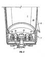
Fig. 3 is a view similar toFig. 2 showing the refill in an intermediate position; -
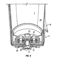
Fig. 4 is a view similar toFigs. 3 and4 showing the refill in its fully engaged position; -
Fig. 5 is a perspective view of the cap assembly prior to assembly; -
Fig. 6 is a perspective view of the cap assembly after assembly; -
Fig. 7 is a cross-section showing the engagement between the bottle neck and cap assembly; -
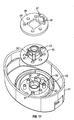
Fig. 8 is a perspective view of the cap with the frangible members intact; -
Fig. 9 is a view similar toFig. 7 after the bottle has been removed from the cap; -
Fig. 10 is a view similar toFig. 8 after the frangible members have broken off; -
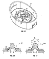
Fig. 11 is an exploded perspective view of a cap of a second refill unit having a relief valve -
Fig. 12 is a view similar toFig. 11 showing the assembled cap; -
Fig. 13 is a cross-sectional view through a pressure relief valve not part of the present invention; and -
Fig. 14 is a view similar toFig. 13 showing the pressure relief valve in an open configuration to allow the flow of air. - The dispenser is a hands-free dispenser which is generally suitable for domestic use. The dispenser is primarily intended to dispense liquid soap, but may also be used to dispense other liquid or semi-liquid products (ideally with a viscosity greater than water), such as hand cream, body lotion, moisturiser, face cream, shampoo, shower gel, foaming hand wash, shaving cream, washing up liquid, toothpaste or a sanitising agent such as alcohol gel.
- The dispenser comprises two main parts, namely a
refill 1 and abase unit 2. Therefill 1 provides a reservoir of liquid to be dispensed and is fitted to thebase unit 2 as set out below. - The base has an
interface 3 into which liquid is dispensed from the refill unit. Theinterface 3 is in fluid communication with a dispensing tube 4. Apump 5 is selectively operable to pump a metered dose of the liquid along dispensing tube 4 and out of dispensinghead 6. - The base has an
infrared transmitter 7A which transmits an infrared beam through a window 8 to areceiver 7B to sense the presence of a user's hands in the vicinity of the dispenser. Control circuitry reacts to a signal from the proximity sensor to activate the pump. The illustrated sensor is a break beam sensor, but may also be a reflective sensor. Although an infrared sensor is shown, any known proximity sensor such as a capacitive sensor may be used. The device may be mains powered or battery powered. Alternatively, it may be a manually operated pump device in which a user pushes a lever to displace the product. - The interface between the
refill 1 andbase unit 2 will now be described in greater detail with reference toFigs. 2 to 10 . - The
base unit 2 comprises acowling 10 which forms a cup-shaped housing surrounding a significant portion of the refill to protect and support it. Aspigot 11 projects through the base of thecowling 10 and is sealed to thecowling 10 by an O-ring seal 12. The spigot has a plurality ofcastellations 13 in its top surface. A second O-ring seal 14 surrounds thespigot 11 beneath thecastellations 13. - The
refill 1 comprises abottle 20 to which acap 21 is fixed. Thebottle 20 has aneck 22 which fits over and seals with anannular flange 23 within thecap 21. Thecap 21 has an upwardly depending skirt 24 (when in the inverted orientation shown in the drawings) which forms the outer surface of the cap. Working inwardly from theskirt 24, the next feature of the cap is an outerannular wall 25 which is generally co-axial with theskirt 24. - This is shown in detail in
Figs. 5 to 10 . - The outer
annular wall 25 consists of a pair of retainingmembers 26 and a pair ofsupport members 27 which alternate with one another and each extend for approximately a quarter of the circle as shown inFigs. 5 ,6 ,8 and10 . The profile of thesupport members 27 is as shown inFig. 2 . These members extend directly up from the lower wall of the cap, are parallel sided and have an inclinedupper surface 28. The profile of the retainingmembers 26 is shown inFigs. 7 and9 . Unlike thesupport members 27, these are not fixed to the wall of the cap. Instead, they are fixed at either end to thesupport members 27 byfrangible members 29 as best shown inFigs. 6 and8 . The retainingmembers 26 are parallel sided and have an inclinedupper surface 35 as shown inFigs. 7 and9 . - As shown in
Figs. 7 and9 , theneck 22 of the bottle has an inclinedouter surface 36 which is complimentary to theinclined surfaces annular wall 25. Behind the inclinedouter surface 36 is ashoulder 37 which faces the main body of thebottle 20. This inclinedouter surface 36 andshoulder 37 is only present in the vicinity of the retainingmembers 26 and not in the vicinity of thesupport members 27. Adjacent to thesupport members 27, theneck 22 has a parallel sided configuration as shown inFig. 2 . - In order to insert the
bottle 20 into thecap 21, thebottle 20 is pushed down with its neck fitting over theannular flange 23. The inclinedouter surface 36 of the bottle co-operates with theinclined surfaces members 26 radially outwardly until theshoulder 37 snaps into place behind the retainingmembers 26 as shown inFig. 7 . When thebottle 20 is pulled off of thecap 21, theshoulders 37 bear against the retainingmembers 26, thereby breakingfrangible members 29 so that the retainingmembers 26 become detached from thecap 21 as shown inFigs. 9 and 10 . Once this has happened, it is no longer possible to retain the cap on a bottle, thereby preventing subsequent use of therefill 1. - It should be noted that it is not necessary for both of the retaining
members 26 to become fully detached from the lid. It is possible that only one of these becomes detached, or that one or both are simply displaced to a location at which they can no longer engage with the neck of the bottle. - Returning now to
Figs. 2 to 4 , the liquid outlet and associated valve will now be described. - The liquid outlet from the reservoir is provided by an
annular wall 30 surrounding acentral opening 31. At the top of theannular wall 30 is an inclined surface 32 (seeFig. 4 ) which provides a valve seat foroutlet valve element 33. This is shown in the form of a U-shape cup-like member, but may equally be a solid member or a hollow ball-like member. Theoutlet valve element 33 is biased into its closed position by a plurality of biasingelements 34. These are attached at their upper end towards the top of thevalve element 33 and are attached at their lower ends at a location radially outward of theannular wall 30 and below the top of theannular wall 30. They are preferably formed integrally with thevalve element 33. - As shown in
Figs. 2 to 4 , when therefill 1 is lowered into thebase unit 2, thespigot 11 engages with the lower surface of thevalve element 33 as shown inFig. 3 . Further downward movement of the refill causes thevalve element 33 to be lifted from its seat, and also brings the O-ring 14 into sealing engagement with theannular wall 30. Thevalve element 33 is lifted to the position shown inFig. 4 . In this position, liquid in thebottle 20 can flow around the biasingelements 34, and enter the spigot via thecastellations 13 and hence flow into thebase unit 2. Liquid is prevented from escaping between thespigot 11 andannular wall 30 by the O-ring seal 14. This arrangement offers a simple and mess-free way for a consumer to insert a refill regardless of the fill level of the refill. - In order to remove a refill, the consumer lifts it out of the base whereupon the biasing
elements 34 cause thevalve element 33 to return to theseat 32. During this movement, the seal between thespigot 11 andannular wall 30 is maintained by the O-ring seal 14. A spent refill is then replaced by a new one following the above procedure. - The cap is provided with a pair of
pressure relief valves 40. Each is formed by anannular boss 41 integral with thecap 21. A pressurerelief valve element 42 is seated on the top of theannular boss 41 and is biased in place by a pair of biasing elements 43 (as shown, for example, inFig. 5 ). The biasing force is such that, under normal conditions, the pressurerelief valve element 42 forms an air tight seal on theboss 41. However, when the pressure within thebottle 20 drops below a certain level, the pressure differential across therelief valve element 42 is sufficient to overcome the force exerted by biasingelements 43 and to allow air into thebottle 20. This reduces the pressure differential thereby restoring the air tight seal without leakage of fluid. - Each
pressure relief valve 40 is surrounded by anannular barrier 44 which extends axially to a level axially above the level of the top of theannular wall 30. Thus, when thevalve element 33 is open, any air entering therelief valve 40 will not become entrained in the outgoing liquid stream. In practice, this means that the relief valve can be placed closer to the outlet, thereby resulting in a more compact cap. Although two relief valves are shown, a single valve, or more than two valves could be provided if necessary. - The manner in which the cap is assembled is illustrated in
Figs. 5 and6 . - The assembly is a three-part structure consisting of the
cap 21, avalve plate 45 and a fixingplate 46. The cap has a number of moulded features including theannular flange 23,annular wall 25 andannular bosses 41. In addition, thecap 21 has a plurality of fixing posts 47. - The
valve plate 45 is an elastomeric material and is integrally formed with thevalve element 33, biasingelements 34,relief valve element 42 and biasingelements 43. The valve plate has a plurality of locatingholes 48 which correspond to the fixing posts 47. - The fixing
plate 46 is made of a rigid plastics material and is integrally formed with theannular barrier 44. As withthe.valve plate 45, the fixingplate 46 is also provided with a plurality of locatingholes 49 which correspond to the fixing posts 47. - To assemble the cap, the three components are placed on top of one another as shown in
Fig. 6 with the fixing posts entering the locating holes to ensure that the components are correctly aligned. Heat or adhesive is then applied to the top of the fixing posts 47 to secure the fixing posts to the fixingplate 46. Theelastomeric valve plate 45 is thereby sandwiched between thecap 21 and fixingplate 46 which holds thevalve elements - A second example of a cap for a refill unit will now be described with reference to
Figs. 11 to 14 . - The structure of the
outlet valve element 33 in the second example is essentially the same as the first example, and will not be described again in relation to the second example. - As can be seen from
Fig. 11 , thecap 21 is integrally molded with a number of features, such as theannular walls conical body 50 of the pressure relief valve which will be described below. A resilient lip 53 (described in more detail below) for the pressure relief valve is provided integrally molded with thevalve plate 45. The fixingplate 46 is also provided with ashield 57 for the relief valve. This is equivalent to thebarrier 44 inFig. 2 , but only extends around the side of the relief valve facing theoutlet valve element 33. Thebarrier 44 andshield 57 could be used interchangeably in the two examples. - The cap assembly is assembled in the same manner as in the first example.
- A
pressure relief valve 60 not part of the present invention is illustrated inFigs. 13 and 14 . - The valve has the
conical body 50 which is an integral part of thecap 21 as mentioned above. At the top of theconical body 50 is acylindrical post 61. Theresilient lip 53 is effectively a hollow frustoconical extension of the valve plate 52 of resilient material which extends along theconical body 50 from which it diverges slightly and is a tight fit against thepost 61. At least one air inlet 62 (also shown inFig. 11 ) passes through the wall of theconical part 50 and is normally covered by theresilient lip 53 as shown inFig. 11 . When the pressure in thebottle 20 falls as liquid is emptied the pressure differential across theresilient lip 53 will eventually become sufficient to displace thelip 53 to a sufficient degree to allow air A into thebottle 20 as shown by the arrows inFig. 8 . It should be noted that the degree to which theresilient lip 53 lifts from theconical body 50 has been exaggerated inFig. 8 and that, in practice, this will be almost imperceptible. - The
resilient lip 53 seals against theconical body 50. In this case, the lip will not diverge from the conical part as shown. Instead, it would actually have an angle of incline less than the angle of theconical body 50 so as to be naturally biased onto the conical part.
Claims (4)
- A container for liquid soap, hand cream, body lotion, moisturiser, face cream, shampoo, shower gel, foaming hand wash, shaving cream, washing up liquid, toothpaste or a sanitising agent having a cap (21) and a bottle (20), the container having an outlet in the cap (21) and being arranged to dispense liquid from the container when in an inverted configuration; wherein the cap (21) has a pressure relief valve (40); characterised in that the pressure relief valve (40) comprises a substantially conical body (50) extending into the container, and tapering inwardly away from an external wall of the container, at least one air inlet (62) passage through the substantially conical body; and a flexible diaphragm (53) extending over the conical body (50), being attached at its outer periphery around the substantially conical body (50) and having a central opening (31) surrounding the substantially conical body (50) above the air inlet passage (62) so as to seal the air inlet passage (62) until the pressure within the container falls below a predetermined level, wherein the diaphragm (53) comprises a resilient lip that seals against the conical body (50).
- A container according to claim 1, wherein the liquid container has an outlet valve (33) to control the flow of liquid out of a container, the flexible diaphragm (53) being integral with the outlet valve (33).
- A container according to claim 2, wherein the outlet valve (33) is resiliently biased by biasing elements (34) which are integral with the diaphragm (53) and outlet valve (33).
- A container according to any of claims 1 to 3, further comprising a shroud in the form of a wall surrounding at least the side of the pressure relief valve (44) facing the outlet.
Priority Applications (1)
| Application Number | Priority Date | Filing Date | Title |
|---|---|---|---|
| EP12157280.4A EP2460737B1 (en) | 2008-11-17 | 2009-11-16 | Refill unit with relief valve |
Applications Claiming Priority (2)
| Application Number | Priority Date | Filing Date | Title |
|---|---|---|---|
| GB0820978A GB0820978D0 (en) | 2008-11-17 | 2008-11-17 | A relief valve |
| PCT/GB2009/002672 WO2010055309A1 (en) | 2008-11-17 | 2009-11-16 | A relief valve |
Related Child Applications (2)
| Application Number | Title | Priority Date | Filing Date |
|---|---|---|---|
| EP12157280.4A Division EP2460737B1 (en) | 2008-11-17 | 2009-11-16 | Refill unit with relief valve |
| EP12157280.4 Division-Into | 2012-02-28 |
Publications (2)
| Publication Number | Publication Date |
|---|---|
| EP2358607A1 EP2358607A1 (en) | 2011-08-24 |
| EP2358607B1 true EP2358607B1 (en) | 2013-11-06 |
Family
ID=40194736
Family Applications (2)
| Application Number | Title | Priority Date | Filing Date |
|---|---|---|---|
| EP09760261.9A Active EP2358607B1 (en) | 2008-11-17 | 2009-11-16 | Container for liquid soap or the like |
| EP12157280.4A Active EP2460737B1 (en) | 2008-11-17 | 2009-11-16 | Refill unit with relief valve |
Family Applications After (1)
| Application Number | Title | Priority Date | Filing Date |
|---|---|---|---|
| EP12157280.4A Active EP2460737B1 (en) | 2008-11-17 | 2009-11-16 | Refill unit with relief valve |
Country Status (15)
| Country | Link |
|---|---|
| US (1) | US8881957B2 (en) |
| EP (2) | EP2358607B1 (en) |
| JP (1) | JP5675645B2 (en) |
| KR (2) | KR101557085B1 (en) |
| CN (1) | CN102216170B (en) |
| AU (1) | AU2009315386B2 (en) |
| BR (1) | BRPI0921856B1 (en) |
| CA (1) | CA2743514A1 (en) |
| GB (1) | GB0820978D0 (en) |
| HK (1) | HK1163036A1 (en) |
| MX (1) | MX2011005087A (en) |
| MY (1) | MY156555A (en) |
| RU (1) | RU2504506C2 (en) |
| WO (1) | WO2010055309A1 (en) |
| ZA (1) | ZA201103616B (en) |
Families Citing this family (9)
| Publication number | Priority date | Publication date | Assignee | Title |
|---|---|---|---|---|
| GB2484935A (en) | 2010-10-26 | 2012-05-02 | Reckitt Benckiser Llc | Container with frangible device interface |
| GB201018005D0 (en) | 2010-10-26 | 2010-12-08 | Reckitt Benckiser Inc | Dispenser for a foaming liquid composition |
| GB201020841D0 (en) | 2010-12-09 | 2011-01-19 | Reckitt & Colman Overseas | Dispenser for a foaming liquid composition with improved foam recovery feature |
| US8616420B2 (en) | 2011-12-15 | 2013-12-31 | The Dial Corporation | Bottle closure with breakaway skirt for non-refillable bottles |
| GB201202578D0 (en) * | 2012-02-15 | 2012-03-28 | Reckitt Benckiser Llc | Dispenser and refill unit and dispensing methods |
| US9884336B2 (en) | 2014-10-10 | 2018-02-06 | The Procter & Gamble Company | Multifunctional dispensing device for dispensing fluid compositions |
| IT201800001827A1 (en) * | 2018-01-25 | 2019-07-25 | Mares Spa | Diaphragm valve and a method for its realization |
| US10988366B2 (en) * | 2018-05-07 | 2021-04-27 | Regina M. GARCIA | Liquid dispenser with proximity and positioning system |
| MX2021014590A (en) | 2019-05-30 | 2022-01-11 | Ecolab Usa Inc | Dispensing system for transferring chemical into a strainer basket assembly. |
Citations (1)
| Publication number | Priority date | Publication date | Assignee | Title |
|---|---|---|---|---|
| WO2008066906A2 (en) * | 2006-11-30 | 2008-06-05 | Thermos L.L.C. | Spill resistant lid assembly for a drink container |
Family Cites Families (10)
| Publication number | Priority date | Publication date | Assignee | Title |
|---|---|---|---|---|
| JPS4620317Y1 (en) * | 1967-12-20 | 1971-07-14 | ||
| US3527551A (en) * | 1968-08-05 | 1970-09-08 | Louis F Kutik | Valve system for pump |
| JPS4857450U (en) * | 1971-11-06 | 1973-07-21 | ||
| DE2803778A1 (en) * | 1978-01-28 | 1979-08-02 | Freudenberg Carl Fa | CHECK VALVE |
| CN2136372Y (en) * | 1992-08-29 | 1993-06-16 | 杜振兴 | Automatic reducing valve |
| JP4455761B2 (en) * | 1998-08-21 | 2010-04-21 | ノーリ、 イー. ハキン、 | Leak-free drinking cup device |
| US6206058B1 (en) | 1998-11-09 | 2001-03-27 | The Procter & Gamble Company | Integrated vent and fluid transfer fitment |
| CN2557765Y (en) * | 2002-06-18 | 2003-06-25 | 吴忠仪表股份有限公司 | Multi-purpose electric controlled valve |
| US7302962B2 (en) * | 2003-10-15 | 2007-12-04 | Trw Automotive U.S. Llc | Vehicle pressure relief valve having peripherally secured flaps and method of manufacturing the same |
| JP4898250B2 (en) * | 2006-03-10 | 2012-03-14 | 株式会社 エスト | Cold water generator and cold / hot water server using the same |
-
2008
- 2008-11-17 GB GB0820978A patent/GB0820978D0/en not_active Ceased
-
2009
- 2009-11-16 AU AU2009315386A patent/AU2009315386B2/en active Active
- 2009-11-16 CN CN2009801455660A patent/CN102216170B/en active Active
- 2009-11-16 EP EP09760261.9A patent/EP2358607B1/en active Active
- 2009-11-16 MY MYPI2011002149A patent/MY156555A/en unknown
- 2009-11-16 WO PCT/GB2009/002672 patent/WO2010055309A1/en active Application Filing
- 2009-11-16 KR KR1020117012452A patent/KR101557085B1/en active IP Right Grant
- 2009-11-16 US US13/129,165 patent/US8881957B2/en active Active
- 2009-11-16 BR BRPI0921856-4A patent/BRPI0921856B1/en not_active IP Right Cessation
- 2009-11-16 MX MX2011005087A patent/MX2011005087A/en active IP Right Grant
- 2009-11-16 KR KR1020157019690A patent/KR101613613B1/en active IP Right Grant
- 2009-11-16 JP JP2011543806A patent/JP5675645B2/en active Active
- 2009-11-16 CA CA 2743514 patent/CA2743514A1/en not_active Abandoned
- 2009-11-16 EP EP12157280.4A patent/EP2460737B1/en active Active
- 2009-11-16 RU RU2011124518/12A patent/RU2504506C2/en active
-
2011
- 2011-05-17 ZA ZA2011/03616A patent/ZA201103616B/en unknown
-
2012
- 2012-04-12 HK HK12103572A patent/HK1163036A1/en unknown
Patent Citations (1)
| Publication number | Priority date | Publication date | Assignee | Title |
|---|---|---|---|---|
| WO2008066906A2 (en) * | 2006-11-30 | 2008-06-05 | Thermos L.L.C. | Spill resistant lid assembly for a drink container |
Also Published As
| Publication number | Publication date |
|---|---|
| HK1163036A1 (en) | 2012-09-07 |
| GB0820978D0 (en) | 2008-12-24 |
| ZA201103616B (en) | 2012-07-25 |
| EP2460737A1 (en) | 2012-06-06 |
| KR20110095278A (en) | 2011-08-24 |
| EP2358607A1 (en) | 2011-08-24 |
| RU2504506C2 (en) | 2014-01-20 |
| KR101557085B1 (en) | 2015-10-02 |
| US20120118430A1 (en) | 2012-05-17 |
| AU2009315386B2 (en) | 2013-12-19 |
| KR20150091182A (en) | 2015-08-07 |
| CA2743514A1 (en) | 2010-05-20 |
| MX2011005087A (en) | 2011-07-29 |
| WO2010055309A1 (en) | 2010-05-20 |
| RU2011124518A (en) | 2012-12-27 |
| CN102216170A (en) | 2011-10-12 |
| JP2012508675A (en) | 2012-04-12 |
| US8881957B2 (en) | 2014-11-11 |
| JP5675645B2 (en) | 2015-02-25 |
| CN102216170B (en) | 2012-08-29 |
| BRPI0921856B1 (en) | 2019-09-17 |
| MY156555A (en) | 2016-02-26 |
| EP2460737B1 (en) | 2015-07-01 |
| AU2009315386A1 (en) | 2010-05-20 |
| BRPI0921856A2 (en) | 2015-12-29 |
| KR101613613B1 (en) | 2016-04-20 |
| US20120261030A2 (en) | 2012-10-18 |
Similar Documents
| Publication | Publication Date | Title |
|---|---|---|
| EP2365933B1 (en) | Dispenser with refill unit | |
| EP2358607B1 (en) | Container for liquid soap or the like | |
| EP2358608B1 (en) | A bottle with a tamper-proof cap | |
| EP3119528B1 (en) | Dispensing device | |
| WO2012123763A2 (en) | Dispenser and refill unit |
Legal Events
| Date | Code | Title | Description |
|---|---|---|---|
| PUAI | Public reference made under article 153(3) epc to a published international application that has entered the european phase |
Free format text: ORIGINAL CODE: 0009012 |
|
| 17P | Request for examination filed |
Effective date: 20110615 |
|
| AK | Designated contracting states |
Kind code of ref document: A1 Designated state(s): AT BE BG CH CY CZ DE DK EE ES FI FR GB GR HR HU IE IS IT LI LT LU LV MC MK MT NL NO PL PT RO SE SI SK SM TR |
|
| RIN1 | Information on inventor provided before grant (corrected) |
Inventor name: YOU, DONG XIAO Inventor name: XIANZHI, ZHOU |
|
| DAX | Request for extension of the european patent (deleted) | ||
| 17Q | First examination report despatched |
Effective date: 20120403 |
|
| GRAP | Despatch of communication of intention to grant a patent |
Free format text: ORIGINAL CODE: EPIDOSNIGR1 |
|
| INTG | Intention to grant announced |
Effective date: 20130828 |
|
| GRAS | Grant fee paid |
Free format text: ORIGINAL CODE: EPIDOSNIGR3 |
|
| GRAA | (expected) grant |
Free format text: ORIGINAL CODE: 0009210 |
|
| AK | Designated contracting states |
Kind code of ref document: B1 Designated state(s): AT BE BG CH CY CZ DE DK EE ES FI FR GB GR HR HU IE IS IT LI LT LU LV MC MK MT NL NO PL PT RO SE SI SK SM TR |
|
| REG | Reference to a national code |
Ref country code: GB Ref legal event code: FG4D |
|
| REG | Reference to a national code |
Ref country code: CH Ref legal event code: EP |
|
| REG | Reference to a national code |
Ref country code: AT Ref legal event code: REF Ref document number: 639290 Country of ref document: AT Kind code of ref document: T Effective date: 20131215 |
|
| REG | Reference to a national code |
Ref country code: IE Ref legal event code: FG4D |
|
| REG | Reference to a national code |
Ref country code: DE Ref legal event code: R096 Ref document number: 602009019944 Country of ref document: DE Effective date: 20140102 |
|
| REG | Reference to a national code |
Ref country code: NL Ref legal event code: VDEP Effective date: 20131106 |
|
| REG | Reference to a national code |
Ref country code: AT Ref legal event code: MK05 Ref document number: 639290 Country of ref document: AT Kind code of ref document: T Effective date: 20131106 |
|
| REG | Reference to a national code |
Ref country code: LT Ref legal event code: MG4D |
|
| PG25 | Lapsed in a contracting state [announced via postgrant information from national office to epo] |
Ref country code: HR Free format text: LAPSE BECAUSE OF FAILURE TO SUBMIT A TRANSLATION OF THE DESCRIPTION OR TO PAY THE FEE WITHIN THE PRESCRIBED TIME-LIMIT Effective date: 20131106 Ref country code: SE Free format text: LAPSE BECAUSE OF FAILURE TO SUBMIT A TRANSLATION OF THE DESCRIPTION OR TO PAY THE FEE WITHIN THE PRESCRIBED TIME-LIMIT Effective date: 20131106 Ref country code: IS Free format text: LAPSE BECAUSE OF FAILURE TO SUBMIT A TRANSLATION OF THE DESCRIPTION OR TO PAY THE FEE WITHIN THE PRESCRIBED TIME-LIMIT Effective date: 20140306 Ref country code: FI Free format text: LAPSE BECAUSE OF FAILURE TO SUBMIT A TRANSLATION OF THE DESCRIPTION OR TO PAY THE FEE WITHIN THE PRESCRIBED TIME-LIMIT Effective date: 20131106 Ref country code: NO Free format text: LAPSE BECAUSE OF FAILURE TO SUBMIT A TRANSLATION OF THE DESCRIPTION OR TO PAY THE FEE WITHIN THE PRESCRIBED TIME-LIMIT Effective date: 20140206 Ref country code: LT Free format text: LAPSE BECAUSE OF FAILURE TO SUBMIT A TRANSLATION OF THE DESCRIPTION OR TO PAY THE FEE WITHIN THE PRESCRIBED TIME-LIMIT Effective date: 20131106 Ref country code: NL Free format text: LAPSE BECAUSE OF FAILURE TO SUBMIT A TRANSLATION OF THE DESCRIPTION OR TO PAY THE FEE WITHIN THE PRESCRIBED TIME-LIMIT Effective date: 20131106 |
|
| PG25 | Lapsed in a contracting state [announced via postgrant information from national office to epo] |
Ref country code: ES Free format text: LAPSE BECAUSE OF FAILURE TO SUBMIT A TRANSLATION OF THE DESCRIPTION OR TO PAY THE FEE WITHIN THE PRESCRIBED TIME-LIMIT Effective date: 20131106 Ref country code: LV Free format text: LAPSE BECAUSE OF FAILURE TO SUBMIT A TRANSLATION OF THE DESCRIPTION OR TO PAY THE FEE WITHIN THE PRESCRIBED TIME-LIMIT Effective date: 20131106 Ref country code: BE Free format text: LAPSE BECAUSE OF FAILURE TO SUBMIT A TRANSLATION OF THE DESCRIPTION OR TO PAY THE FEE WITHIN THE PRESCRIBED TIME-LIMIT Effective date: 20131106 Ref country code: AT Free format text: LAPSE BECAUSE OF FAILURE TO SUBMIT A TRANSLATION OF THE DESCRIPTION OR TO PAY THE FEE WITHIN THE PRESCRIBED TIME-LIMIT Effective date: 20131106 |
|
| PG25 | Lapsed in a contracting state [announced via postgrant information from national office to epo] |
Ref country code: PT Free format text: LAPSE BECAUSE OF FAILURE TO SUBMIT A TRANSLATION OF THE DESCRIPTION OR TO PAY THE FEE WITHIN THE PRESCRIBED TIME-LIMIT Effective date: 20140306 |
|
| REG | Reference to a national code |
Ref country code: CH Ref legal event code: PL |
|
| PG25 | Lapsed in a contracting state [announced via postgrant information from national office to epo] |
Ref country code: CH Free format text: LAPSE BECAUSE OF NON-PAYMENT OF DUE FEES Effective date: 20131130 Ref country code: LI Free format text: LAPSE BECAUSE OF NON-PAYMENT OF DUE FEES Effective date: 20131130 Ref country code: EE Free format text: LAPSE BECAUSE OF FAILURE TO SUBMIT A TRANSLATION OF THE DESCRIPTION OR TO PAY THE FEE WITHIN THE PRESCRIBED TIME-LIMIT Effective date: 20131106 |
|
| REG | Reference to a national code |
Ref country code: DE Ref legal event code: R097 Ref document number: 602009019944 Country of ref document: DE |
|
| REG | Reference to a national code |
Ref country code: IE Ref legal event code: MM4A |
|
| PG25 | Lapsed in a contracting state [announced via postgrant information from national office to epo] |
Ref country code: RO Free format text: LAPSE BECAUSE OF FAILURE TO SUBMIT A TRANSLATION OF THE DESCRIPTION OR TO PAY THE FEE WITHIN THE PRESCRIBED TIME-LIMIT Effective date: 20131106 Ref country code: PL Free format text: LAPSE BECAUSE OF FAILURE TO SUBMIT A TRANSLATION OF THE DESCRIPTION OR TO PAY THE FEE WITHIN THE PRESCRIBED TIME-LIMIT Effective date: 20131106 Ref country code: CZ Free format text: LAPSE BECAUSE OF FAILURE TO SUBMIT A TRANSLATION OF THE DESCRIPTION OR TO PAY THE FEE WITHIN THE PRESCRIBED TIME-LIMIT Effective date: 20131106 Ref country code: SK Free format text: LAPSE BECAUSE OF FAILURE TO SUBMIT A TRANSLATION OF THE DESCRIPTION OR TO PAY THE FEE WITHIN THE PRESCRIBED TIME-LIMIT Effective date: 20131106 Ref country code: IT Free format text: LAPSE BECAUSE OF FAILURE TO SUBMIT A TRANSLATION OF THE DESCRIPTION OR TO PAY THE FEE WITHIN THE PRESCRIBED TIME-LIMIT Effective date: 20131106 |
|
| PLBE | No opposition filed within time limit |
Free format text: ORIGINAL CODE: 0009261 |
|
| STAA | Information on the status of an ep patent application or granted ep patent |
Free format text: STATUS: NO OPPOSITION FILED WITHIN TIME LIMIT |
|
| PG25 | Lapsed in a contracting state [announced via postgrant information from national office to epo] |
Ref country code: DK Free format text: LAPSE BECAUSE OF FAILURE TO SUBMIT A TRANSLATION OF THE DESCRIPTION OR TO PAY THE FEE WITHIN THE PRESCRIBED TIME-LIMIT Effective date: 20131106 |
|
| 26N | No opposition filed |
Effective date: 20140807 |
|
| PG25 | Lapsed in a contracting state [announced via postgrant information from national office to epo] |
Ref country code: IE Free format text: LAPSE BECAUSE OF NON-PAYMENT OF DUE FEES Effective date: 20131116 |
|
| REG | Reference to a national code |
Ref country code: DE Ref legal event code: R097 Ref document number: 602009019944 Country of ref document: DE Effective date: 20140807 |
|
| PG25 | Lapsed in a contracting state [announced via postgrant information from national office to epo] |
Ref country code: SI Free format text: LAPSE BECAUSE OF FAILURE TO SUBMIT A TRANSLATION OF THE DESCRIPTION OR TO PAY THE FEE WITHIN THE PRESCRIBED TIME-LIMIT Effective date: 20131106 |
|
| PG25 | Lapsed in a contracting state [announced via postgrant information from national office to epo] |
Ref country code: MC Free format text: LAPSE BECAUSE OF FAILURE TO SUBMIT A TRANSLATION OF THE DESCRIPTION OR TO PAY THE FEE WITHIN THE PRESCRIBED TIME-LIMIT Effective date: 20131106 |
|
| PG25 | Lapsed in a contracting state [announced via postgrant information from national office to epo] |
Ref country code: SM Free format text: LAPSE BECAUSE OF FAILURE TO SUBMIT A TRANSLATION OF THE DESCRIPTION OR TO PAY THE FEE WITHIN THE PRESCRIBED TIME-LIMIT Effective date: 20131106 |
|
| PG25 | Lapsed in a contracting state [announced via postgrant information from national office to epo] |
Ref country code: CY Free format text: LAPSE BECAUSE OF FAILURE TO SUBMIT A TRANSLATION OF THE DESCRIPTION OR TO PAY THE FEE WITHIN THE PRESCRIBED TIME-LIMIT Effective date: 20131106 Ref country code: TR Free format text: LAPSE BECAUSE OF FAILURE TO SUBMIT A TRANSLATION OF THE DESCRIPTION OR TO PAY THE FEE WITHIN THE PRESCRIBED TIME-LIMIT Effective date: 20131106 |
|
| PG25 | Lapsed in a contracting state [announced via postgrant information from national office to epo] |
Ref country code: HU Free format text: LAPSE BECAUSE OF FAILURE TO SUBMIT A TRANSLATION OF THE DESCRIPTION OR TO PAY THE FEE WITHIN THE PRESCRIBED TIME-LIMIT; INVALID AB INITIO Effective date: 20091116 Ref country code: MK Free format text: LAPSE BECAUSE OF FAILURE TO SUBMIT A TRANSLATION OF THE DESCRIPTION OR TO PAY THE FEE WITHIN THE PRESCRIBED TIME-LIMIT Effective date: 20131106 Ref country code: BG Free format text: LAPSE BECAUSE OF FAILURE TO SUBMIT A TRANSLATION OF THE DESCRIPTION OR TO PAY THE FEE WITHIN THE PRESCRIBED TIME-LIMIT Effective date: 20131106 Ref country code: LU Free format text: LAPSE BECAUSE OF NON-PAYMENT OF DUE FEES Effective date: 20131116 |
|
| PG25 | Lapsed in a contracting state [announced via postgrant information from national office to epo] |
Ref country code: GR Free format text: LAPSE BECAUSE OF NON-PAYMENT OF DUE FEES Effective date: 20131106 Ref country code: MT Free format text: LAPSE BECAUSE OF FAILURE TO SUBMIT A TRANSLATION OF THE DESCRIPTION OR TO PAY THE FEE WITHIN THE PRESCRIBED TIME-LIMIT Effective date: 20131106 |
|
| REG | Reference to a national code |
Ref country code: FR Ref legal event code: PLFP Year of fee payment: 7 |
|
| PG25 | Lapsed in a contracting state [announced via postgrant information from national office to epo] |
Ref country code: GR Free format text: LAPSE BECAUSE OF FAILURE TO SUBMIT A TRANSLATION OF THE DESCRIPTION OR TO PAY THE FEE WITHIN THE PRESCRIBED TIME-LIMIT Effective date: 20140207 |
|
| REG | Reference to a national code |
Ref country code: FR Ref legal event code: PLFP Year of fee payment: 8 |
|
| REG | Reference to a national code |
Ref country code: FR Ref legal event code: PLFP Year of fee payment: 9 |
|
| REG | Reference to a national code |
Ref country code: FR Ref legal event code: PLFP Year of fee payment: 10 |
|
| REG | Reference to a national code |
Ref country code: GB Ref legal event code: 732E Free format text: REGISTERED BETWEEN 20200917 AND 20200923 |
|
| REG | Reference to a national code |
Ref country code: DE Ref legal event code: R081 Ref document number: 602009019944 Country of ref document: DE Owner name: RECKITT & COLMAN (OVERSEAS) HEALTH LTD., SLOUG, GB Free format text: FORMER OWNER: RECKITT & COLMAN (OVERSEAS) LTD., SLOUGH BERKSHIRE SL1 3UH, GB |
|
| P01 | Opt-out of the competence of the unified patent court (upc) registered |
Effective date: 20230513 |
|
| PGFP | Annual fee paid to national office [announced via postgrant information from national office to epo] |
Ref country code: GB Payment date: 20230928 Year of fee payment: 15 |
|
| PGFP | Annual fee paid to national office [announced via postgrant information from national office to epo] |
Ref country code: FR Payment date: 20230911 Year of fee payment: 15 |
|
| PGFP | Annual fee paid to national office [announced via postgrant information from national office to epo] |
Ref country code: DE Payment date: 20230919 Year of fee payment: 15 |