EP2358252B1 - Steam mop - Google Patents
Steam mop Download PDFInfo
- Publication number
- EP2358252B1 EP2358252B1 EP09771128.7A EP09771128A EP2358252B1 EP 2358252 B1 EP2358252 B1 EP 2358252B1 EP 09771128 A EP09771128 A EP 09771128A EP 2358252 B1 EP2358252 B1 EP 2358252B1
- Authority
- EP
- European Patent Office
- Prior art keywords
- steam
- frame
- mop
- water
- housing
- Prior art date
- Legal status (The legal status is an assumption and is not a legal conclusion. Google has not performed a legal analysis and makes no representation as to the accuracy of the status listed.)
- Active
Links
Images







Classifications
-
- A—HUMAN NECESSITIES
- A47—FURNITURE; DOMESTIC ARTICLES OR APPLIANCES; COFFEE MILLS; SPICE MILLS; SUCTION CLEANERS IN GENERAL
- A47L—DOMESTIC WASHING OR CLEANING; SUCTION CLEANERS IN GENERAL
- A47L13/00—Implements for cleaning floors, carpets, furniture, walls, or wall coverings
- A47L13/10—Scrubbing; Scouring; Cleaning; Polishing
- A47L13/20—Mops
- A47L13/22—Mops with liquid-feeding devices
-
- A—HUMAN NECESSITIES
- A47—FURNITURE; DOMESTIC ARTICLES OR APPLIANCES; COFFEE MILLS; SPICE MILLS; SUCTION CLEANERS IN GENERAL
- A47L—DOMESTIC WASHING OR CLEANING; SUCTION CLEANERS IN GENERAL
- A47L13/00—Implements for cleaning floors, carpets, furniture, walls, or wall coverings
- A47L13/10—Scrubbing; Scouring; Cleaning; Polishing
- A47L13/20—Mops
- A47L13/22—Mops with liquid-feeding devices
- A47L13/225—Steam mops
-
- A—HUMAN NECESSITIES
- A47—FURNITURE; DOMESTIC ARTICLES OR APPLIANCES; COFFEE MILLS; SPICE MILLS; SUCTION CLEANERS IN GENERAL
- A47L—DOMESTIC WASHING OR CLEANING; SUCTION CLEANERS IN GENERAL
- A47L13/00—Implements for cleaning floors, carpets, furniture, walls, or wall coverings
- A47L13/10—Scrubbing; Scouring; Cleaning; Polishing
- A47L13/20—Mops
- A47L13/24—Frames for mops; Mop heads
- A47L13/254—Plate frames
Definitions
- the invention relates generally to a fluid mop, and more particularly to a steam mop.
- wet and dry mops have been widely used for cleaning floors.
- a type of wet mop is a steam mop, which works as a steaming device.
- Steaming devices used to apply steam to household objects are well known. The uses of the devices vary widely, and may include the application of steam to drapes or other fabrics to remove wrinkles, and the application of steam to objects to assist in cleaning various objects.
- Typical steam devices have a reservoir for storing water that is connected to an electrical water pump with an on/off switch.
- the electric water pump outlet is connected to a steam boiler with a heating element to heat the water.
- the heated water generates steam, which may be directed towards its intended destination through a nozzle which controls the application of the steam.
- An indication to the user when the water supply has depleted in the reservoir of the steam device is preferred. For instance, there may be a safety device to sense if the water is below a minimum threshold which in turn either turns on an indication light or automatically turns off the boiler in the mop. Typically, this provides an indication to the user to replenish the water supply after the water supply in the reservoir has been depleted.
- Variation of the shapes and sizes of nozzles allows for preferred distribution of generated steam to an object to be cleaned.
- the nozzles may be disconnectable from the steam generator to allow different nozzles to be utilized, based on the object to be steamed.
- the nozzle may be either closely coupled to the steam generator, or located at a distance from the steam generator, requiring tubing or other steam transfer structures to be interconnected between the steam generator and the discharge nozzle.
- a universal type of opening in the steam device is needed to connect to the various types of mop frames, nozzles and or tubing.
- an improved steam mop to improve ease of use, such as a water reservoir that shows a current indication of what the water supply a mop housing that easily disconnects from a steam frame and has an improved steam pocket and frame.
- a steam mop comprising a housing containing a water tank having a water inlet and a water outlet, and a water pump having a pump inlet and a pump outlet, the water pump being configured to pump water from the water tank to a boiler.
- a steam mop according to the present invention is characterised in that the housing includes at least one window to allow viewing of the level of water remaining in the water tank, and further including a LED positioned in the water tank to illuminate the water tank to improve the visibility of the water level in the tank.
- the housing is easily disconnected from an adapter on the steam frame.
- the invention accordingly comprises a product possessing the features, properties, and the relation of components which will be exemplified in the product hereinafter described, and the scope of the invention will be indicated in the claims.
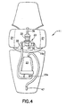
- FIG. 4 is a front elevational view of the mop housing in section showing connections for reservoir, boiler and steam mop frame in accordance with one embodiment of the invention
- FIG. 5 is an elevation view in section of the pump and boiler of FIG. 4 ;
- FIG. 6 is a plan view of a steam pocket frame for use with the steam mop of FIG. 1 ;
- FIG. 7 is a front perspective view of a fabric steam pocket suitable for use with the steam frame of FIG. 6 ;
- FIG. 8 is a plan view of a mop handle suitable for use with the steam mop of FIG. 1 ;
- FIG. 9 is an exploded perspective view showing how the steam mop frame assembly is installed on mop housing of FIGS. 1-3 in accordance with one embodiment of the invention.
- FIG. 10 is a perspective view of an upper connector piece of the connector in FIG. 9 ;
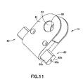
- FIG. 11 is a perspective view of a fluid distributor of the connector of FIG. 10 ;
- FIG. 12 is an elevational view in partial section of the fluid distributor of FIG. 11 ;
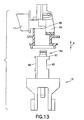
- FIG. 13 is an exploded view in section showing how the connector attaches to the housing
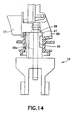
- FIG 14 is a section view of the frame connector engages by the latch of the housing
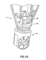
- FIG. 15 is a front perspective view of the housing in section showing how the latch engages the notch of frame connector
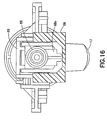
- FIG. 16 is a top perspective view of arm of release button that engages stem of connector
- FIG. 17 is a perspective view of a steam mop having a universal connector and steam frame with a central steam manifold constructed and arranged in accordance with an embodiment of the invention
- FIG. 18 is a perspective view of the steam mop frame and universal connector of FIG. 17 in accordance with the invention.
- FIG. 19 is a perspective view of the universal connecter shown in FIGS. 17 and 18 ;
- FIG. 20 is rear perspective view of the steam frame shown in FIGS. 17 and 18 .
- FIG. 1 is a perspective view of a steam mop 10 constructed and arranged in accordance with the invention.
- Mop 10 includes an elongated housing 11 with a water reservoir 21 and a boiler 23 and an upper tube 12a and a lower tube 12b connected to one end of housing 11.
- a handle 13 is attached to the end of upper tube 12a.
- a steam frame 14 with an installed steam pocket 15 is operatively connected to the other end of housing 11 by a connector 16.
- connector 16 and frame 14 may be removed from housing 11 by pressing a release button 17 at the base of housing 11.
- Water is introduced into a reservoir 21 at a water inlet or opening 18a.
- the level of water present in a reservoir 21 in housing 11 shown in FIG. 3 can be viewed through a sighting window 19.
- the specifics of fabric steam pocket 15 will be described below.
- FIGS. 2A and 2B are perspective side views of housing 11.
- Water inlet 18a has a water cap 18b that is removed for filling to exposed opening 18a.
- the region around opening 18a is shaped like a funnel 20 allows a user to fill reservoir 21 without spilling.
- Housing 11 also includes at least one sighting window 19 that allows a user to observe the water level in water container 21.
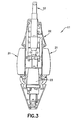
- FIG. 3 is a front plan view in section showing the location of elements in housing 11.
- Water container 21 is positioned adjacent and surrounds a boiler 23.
- a one-way pump 22 pumps water from reservoir 21 to boiler 23 in response to the push-pull movement of mop 10. This movement of handle 13 causes operation of one way valve 22 as will be described in detail below.
- water container 21 wraps around the back of housing 11.
- FIG. 4 is a detailed front view of showing how water container 21, showing the hoses connecting one-way pump 22 and boiler 23 as described in connection with FIG. 5 .
- Water pump 22 includes a pump body 33 having a pump cavity 33a.
- a pump piston 34 is connected to a push rod 36 which in turn is connected to pole 12 or handle 13.
- piston 34 creates a negative pressure in cavity 33a. This draws water from reservoir 21 into a water supply hose 27a that feeds into pump water inlet 27 through a one-way inlet valve 37 to fill cavity 33a.
- piston 34 moves downward and water in cavity 33a is expelled through a one-way outlet valve 38 into pump outlet hose 28.
- This water is then introduced into a boiler inlet 23a in boiler 23.
- Water in boiler 23 is heated by a heating element 39 in a boiler cavity 41.
- Heating element 39 is connected to electrical connectors 39a and 39b.
- Steam generated in boiler cavity 41 is fed through a steam valve 42 into a steam chamber 43. Steam is then expelled through a steam outlet 44 to a steam hose 46 and to a steam outlet fitting 47.
- One-way inlet valve 37 and one-way outlet valve 38 are duck-bill valves formed of a flexible elastomeric material, such a rubber.
- the valves are conical in shape so that when handle 13 is pulled, water is drawn through inlet valve 37 while outlet valve 38 remains closed. Similarly, when handle 13 is pushed, water is forced out through outlet valve 38 and inlet valve 37 remains closed and water is fed into boiler 23.
- a mechanical bellow pump that may be used in steam mop housing 11 to pump water from water container 21 to boiler 23.
- the pump can be a two-way piston pump that pumps water when its piston is displaced both in the forward direction and also in the return backwards motion. This type of pump is shown in co-pending application Serial No. 11/842,478 .
- Steam pocket frame 14 is substantially rectangular and includes a front wall 51, a rear wall 52, a right side wall 53, and a left side wall 54. Front wall 51 and rear wall 52 provides additional firm surface area to help dry the floor.
- baffles 56 are planar slats and extends from front wall 51 to rear wall 52 within frame 14. Baffles 56 provide structure to frame 14 but do not extend from top to bottom. Baffles 56 alternate position on the top and bottom forming an upper surface and a lower surface for supporting fabric steam pocket 15.
- baffles 56 may extend diagonally from front wall 51 to rear wall 52 within frame 14.
- Rear wall 52 of frame 14 has an opening 59 that is substantially about the middle of rear wall 52 for mounting connector 16 to connect to steam generated in boiler 23.
- Connector 16 includes an upper stem end 16a with a steam inlet 16b (as shown in FIG. 9 ) for connecting to steam outlet fitting 47 in housing 11.
- the lower section of connector 16 includes bottom end having a pair of steam nozzles 16c for connecting to steam frame 14.
- Steam nozzle 16c on the right side of connector 16 provides steam to steam chamber 57a on the right.
- Steam nozzle 16c on the left side of connector 16 provides steam to steam chamber 57 on the left.
- pocket 15 is configured to slip over frame 14 in accordance with one embodiment of the present invention.
- pocket 15 is formed of a first layer of fabric 15a and an opposed second layer of fabric 15b (not shown).
- Fabric layers 15a and 15b each have a substantially rectangular shape with two opposed long edges 15c and 15d and two opposed short sides 15e and 15f. Long edge 15c and two opposed short side 15e and 15f are stitched to form pocket 15.
- fabric steam pocket 15 is open on long edge 15d.
- the fabric along the opening on long edge 15d may be optionally closed with a hook and loop fastener, buttons or snaps.
- steam pocket 15 is cut along a line 62 to form a slot 63 around the width of connector 16 on the first layer 15a and opposed second layer 15b to fit around connector body 16.
- Slot 63 has a length a distance 62a from rear edge 15d to about the pair of nozzles 16c shown in FIG. 7 . This allows for vertical rotation of housing 11 without bending the fabric of fabric steam pocket 15 and use of both sides of steam pocket 15 for cleaning without having to remove and re-install steam pocket 15.
- steam pocket 15 is a cloth or towel.
- Steam pocket may be formed of any suitable fabric such as cotton or a synthetic fabric, such as polyester or polyolefin fiber.
- the fabric of pocket 15 is a microfiber.
- the microfiber is a synthetic polyester microfiber.
- FIG. 10 shows an upper connector piece 71 of a universal connector as shown in co-pending application Serial No. 12/118,015 .
- Upper piece 71 has a stem 16a with a steam inlet 16b for connection to steam outlet fitting 47 in housing 11
- connector 71 includes a pair of inner pivot plates 72 with pivot buttons 73 at the lower end for pivotal connection to a fluid distributor 74 as shown in FIG. 11 .
- Fluid distributor 74 includes a hollow nipple portion 76 and a pair of arms 83 that engages frame 14 as will be discussed in more detail below.
- frame 14 has a pair of receiving slots as shown in the co-pending application with a key hole piece for receiving and for engaging fluid distributor 74.
- fluid distributor 74 includes two upwardly extending distributor plates 81 with holes 82 for aligning with pivot buttons 73 of upper connector inner pivot plates 72 to provide the right and left pivot connection between upper connector piece 71 and fluid distributor 74.
- fluid distributor 74 includes hollow nipple portion 76 for connecting to the fluid source. Hollow nipple portion 76 in turn connects to upper connector piece 71 and stem 16a is connected to the fluid source of housing 11. Pivot arms 83 that fit into receiving slots 78 of frame 14 for connecting connector 16 to mop frame 14 for pivoting up and down are also hollow. Each arm 83 includes a fluid opening 83a. Distributor arms 83 have two opposed flat surfaces 83b and 83c at their respective ends for coupling to frame 14. Fluid enters hollow nipple portion 76 and is transported through opening 83a to frame 14.
- FIG. 13 is an exploded perspective view showing how steam frame 14 is installed on or removed from housing 11, by movement in a direction indicated by arrow A.
- Release button 17 may have an indentation or a rubberized surface to prevent slippage when user presses release button 17 to detach steam frame 14 from housing 11.
- Release button 17 may be a spring loaded or hinge type button so that on depressing button 17, stem 16a is released.
- FIGS. 14 and 15 show how stem 16a of connector 16 is engaged within opening 64 in housing 11.
- stem 16a is tubular shaped and opening 64 is also tubular shaped to insure that connector 16 is properly aligned when frame 14 is connected to housing 11.
- Release button 17 has an arm 68 with a u-shaped opening 68a that surrounds flange 67 on stem 16a when button 17 is biased outwardly.
- a latch 69 fits within notch 65 and secures stem 16a within housing 11.
- arm 68 urges latch 69 to and disconnect from to a notch 65 on connector 16 defined by flange 67.
- Connector 16 is installed on housing 11 by inserting stem 16a into opening 64 of housing 11.
- U-shaped opening 68a on arm 68 that was aligned with the axis of opening 64 is displayed and then latch 69 engages notch 65 on connector 16.
- a user merely presses release button 17 so arm 68 moves u-shaped opening 68a to push latch 69 away from notch 65.
- stem 16a may be key shaped and opening 64 is also key shaped to insure that connector 16 is properly attached to housing 11.
- FIG. 16 is a top perspective view of arm 68 of release button 17 that shows how arm 68 controls latch 69 of connector 16.
- FIG. 17 illustrates a steam mop 310 and a steam frame 314 constructed and arranged in accordance with the invention.
- Mop 310 includes an elongated housing 311 with a water reservoir 321 and a boiler 323.
- a pole 312 having an upper tube section 312a and a lower tube section 312b connected to one end of housing 311.
- a handle 313 is attached to the end of upper tube 312a.
- Steam frame 314 is operatively connected to the other end of housing 311 by a universal connector 316 constructed and arranged in accordance with the invention.
- connector 316 and frame 314 may be removed from housing 11 by pressing a release button 317 at the base of housing 311. Water is introduced into reservoir 321 at a water inlet or opening 318a. The level of water present in a reservoir 321 in housing 311 can be viewed through a sighting window 319.
- FIGS. 4 and 5 The details and operation of the steam mop components in housing 311 are shown and described in connection with FIGS. 4 and 5 . While a mechanical pump has been described in connection with this embodiment it is within the scope of the invention to utilize an electrical pump. Such an electrical pump can be actuated by a micro-switch or a motor switch.
- FIG. 18 is a perspective view showing the details of construction of a universal connector 416 and steam frame 414 of the type used in mop 310 of FIG. 17 .
- Frame 414 is substantially rectangular in shape, open at the top and bottom with a plurality of baffles 431.
- Universal connector 416 includes an upper connector piece 422 similar in construction to upper connector piece 22 in FIG. 10 that allows frame 414 and housing 411 to pivot side to side and up and down with respect to each other.
- Upper connection piece 422 is pivotally connected to a lower connection piece 426 having a different construction.
- lower connection piece includes two pivot arms 428a and 428b with a central opening 428c for passage of a flexible steam hose 430 to feed steam to frame 414.
- Frame 414 includes a connector receiving slot 414a for receiving arms 428a and 428b pivotally secured to there by cylindrical cavities 432 below two mounting plates 432a and 432b to allow for rotation of arms 428a and 428b. This is shown in the rear perspective in FIG. 20 .
- steam frame 414 includes a central steam passageway or manifold 433 that runs from the rear of frame 414 at receiving slot 414a to a front border 414b.
- a plurality of steam release openings 434 are formed on both sides of manifold 433 along the top and bottom thereof. These release openings 434 are positioned between each baffle 431.
- Baffles 431 are substantially orthogonal to manifold 433 in the center of frame 414 and extend sideways and curve rearward to the side edges and rear wall of frame 414.
- Steam frame 414 includes a rear wall 414a with a connector receiving opening 415 in the center of rear wall 414a, a front wall 414b and a right side wall 414c and a left side wall 414d.
- Steam hose 430 is connected to manifold 433 by a hose plate 431 mounted at the entrance to manifold 433.
- Short fins 435 extend from the sides of manifold 433 and edges 414c and 414d approximately at the mid-height of manifold 433 and side walls 414c and 414d to assist in distribution of steam to the upper and lower surfaces of a steam towel installed on frame 414 when in use.
- Universal connector 16, 216 and 416 provides many advantages for ease of use because they easily connect and disconnect to a mop handle and a mop frame while providing a user with universal pivoting and steering capability.
- the user has more control of the appliance and frame by the universal connection to clean whatever areas that need to be clean and allows use of both sides of steam frame 14, 114, 314 and 414 for cleaning.
- the mop frame may be rotated for easy steering and allows a user to use both sides of the mop steam frame to clean.
- the universal connector may attached to any variety of differently shaped mop frames.
- Steam mops 11 and 310 provide many advantages for ease of use because it eliminates the need for an electric water pump and an on/off switch to activate the electric water pump.
- the user has more control over that amount of water needed to be discharged into the boiler and consequently, how much steam is needed by moving the mop forwards and backwards.
- steam mop is designed as a low pressure or non-pressurized system so it is safer for the user to use.
- the boiler can create steam is a short amount of time.
- Steam mop also provides a water reservoir with windows and a LED light to show the water level of the reservoir.
- Steam housing easily connects and disconnects to a mop handle and a mop frame while providing a user with universal steering capability. The user has more control of the mop frame by the connection to the mop frame to clean whatever areas that need to be clean and allows use of both sides of steam frame for cleaning.
- the mop frame may be rotated so that the user may use both sides of the mop frame to clean.
- design of the steam frame may attached to any variety of differently shaped mop frames.
Landscapes
- Cleaning Implements For Floors, Carpets, Furniture, Walls, And The Like (AREA)
- Cleaning By Liquid Or Steam (AREA)
Description
- The invention relates generally to a fluid mop, and more particularly to a steam mop.
- Wet and dry mops have been widely used for cleaning floors. A type of wet mop is a steam mop, which works as a steaming device. Steaming devices used to apply steam to household objects are well known. The uses of the devices vary widely, and may include the application of steam to drapes or other fabrics to remove wrinkles, and the application of steam to objects to assist in cleaning various objects.
- Typical steam devices have a reservoir for storing water that is connected to an electrical water pump with an on/off switch. The electric water pump outlet is connected to a steam boiler with a heating element to heat the water. The heated water generates steam, which may be directed towards its intended destination through a nozzle which controls the application of the steam.
- An indication to the user when the water supply has depleted in the reservoir of the steam device is preferred. For instance, there may be a safety device to sense if the water is below a minimum threshold which in turn either turns on an indication light or automatically turns off the boiler in the mop. Typically, this provides an indication to the user to replenish the water supply after the water supply in the reservoir has been depleted.
- Variation of the shapes and sizes of nozzles allows for preferred distribution of generated steam to an object to be cleaned. The nozzles may be disconnectable from the steam generator to allow different nozzles to be utilized, based on the object to be steamed. The nozzle may be either closely coupled to the steam generator, or located at a distance from the steam generator, requiring tubing or other steam transfer structures to be interconnected between the steam generator and the discharge nozzle. Thus, a universal type of opening in the steam device is needed to connect to the various types of mop frames, nozzles and or tubing.
- Accordingly, it is desirable to provide an improved steam mop to improve ease of use, such as a water reservoir that shows a current indication of what the water supply a mop housing that easily disconnects from a steam frame and has an improved steam pocket and frame.
- It is known from
WO2008/016741 to provide a steam mop comprising a housing containing a water tank having a water inlet and a water outlet, and a water pump having a pump inlet and a pump outlet, the water pump being configured to pump water from the water tank to a boiler. - A steam mop according to the present invention is characterised in that the housing includes at least one window to allow viewing of the level of water remaining in the water tank, and further including a LED positioned in the water tank to illuminate the water tank to improve the visibility of the water level in the tank.
- In a preferred embodiment the housing is easily disconnected from an adapter on the steam frame.
- Preferred features of the invention are defined in the dependent claims numbers 2 to 10.
- The invention accordingly comprises a product possessing the features, properties, and the relation of components which will be exemplified in the product hereinafter described, and the scope of the invention will be indicated in the claims.
- For a fuller understanding of the invention, reference is made to the following description taken in connection with the accompanying drawing(s), in which:
-
Figure 1 is a perspective view of a steam mop constructed and arranged in accordance with one embodiment of the invention; -
Figures 2 A and 2B are perspective side views of the mop housing in the steam mop of -
Figure 1 showing the water inlet and funnel; -
Figure 3 is a front view of the mop housing in section showing a reservoir, a pump and a boiler ofFigure 1 ; -
FIG. 4 is a front elevational view of the mop housing in section showing connections for reservoir, boiler and steam mop frame in accordance with one embodiment of the invention; -
FIG. 5 is an elevation view in section of the pump and boiler ofFIG. 4 ; -
FIG. 6 is a plan view of a steam pocket frame for use with the steam mop ofFIG. 1 ; -
FIG. 7 is a front perspective view of a fabric steam pocket suitable for use with the steam frame ofFIG. 6 ; -
FIG. 8 is a plan view of a mop handle suitable for use with the steam mop ofFIG. 1 ; -
FIG. 9 is an exploded perspective view showing how the steam mop frame assembly is installed on mop housing ofFIGS. 1-3 in accordance with one embodiment of the invention; -
FIG. 10 is a perspective view of an upper connector piece of the connector inFIG. 9 ; -
FIG. 11 is a perspective view of a fluid distributor of the connector ofFIG. 10 ; -
FIG. 12 is an elevational view in partial section of the fluid distributor ofFIG. 11 ; -
FIG. 13 is an exploded view in section showing how the connector attaches to the housing; -
FIG 14 is a section view of the frame connector engages by the latch of the housing; -
FIG. 15 is a front perspective view of the housing in section showing how the latch engages the notch of frame connector; -
FIG. 16 is a top perspective view of arm of release button that engages stem of connector; -
FIG. 17 is a perspective view of a steam mop having a universal connector and steam frame with a central steam manifold constructed and arranged in accordance with an embodiment of the invention; -
FIG. 18 is a perspective view of the steam mop frame and universal connector ofFIG. 17 in accordance with the invention; -
FIG. 19 is a perspective view of the universal connecter shown inFIGS. 17 and18 ; and -
FIG. 20 is rear perspective view of the steam frame shown inFIGS. 17 and18 . -
FIG. 1 is a perspective view of asteam mop 10 constructed and arranged in accordance with the invention.Mop 10 includes anelongated housing 11 with awater reservoir 21 and aboiler 23 and anupper tube 12a and alower tube 12b connected to one end ofhousing 11. Ahandle 13 is attached to the end ofupper tube 12a. Asteam frame 14 with an installedsteam pocket 15 is operatively connected to the other end ofhousing 11 by aconnector 16. In this embodiment,connector 16 andframe 14 may be removed fromhousing 11 by pressing arelease button 17 at the base ofhousing 11. Water is introduced into areservoir 21 at a water inlet or opening 18a. The level of water present in areservoir 21 inhousing 11 shown inFIG. 3 can be viewed through asighting window 19. The specifics offabric steam pocket 15 will be described below. -
FIGS. 2A and 2B are perspective side views ofhousing 11.Water inlet 18a has awater cap 18b that is removed for filling to exposedopening 18a. The region around opening 18a is shaped like afunnel 20 allows a user to fillreservoir 21 without spilling.Housing 11 also includes at least onesighting window 19 that allows a user to observe the water level inwater container 21. -
FIG. 3 is a front plan view in section showing the location of elements inhousing 11.Water container 21 is positioned adjacent and surrounds aboiler 23. A one-way pump 22 pumps water fromreservoir 21 toboiler 23 in response to the push-pull movement ofmop 10. This movement ofhandle 13 causes operation of oneway valve 22 as will be described in detail below. Here,water container 21 wraps around the back ofhousing 11. -
FIG. 4 is a detailed front view of showing howwater container 21, showing the hoses connecting one-way pump 22 andboiler 23 as described in connection withFIG. 5 .Water pump 22 includes apump body 33 having apump cavity 33a. Apump piston 34 is connected to apush rod 36 which in turn is connected topole 12 or handle 13. As mop handle 13 is pulled by auser piston 34 creates a negative pressure incavity 33a. This draws water fromreservoir 21 into awater supply hose 27a that feeds intopump water inlet 27 through a one-way inlet valve 37 to fillcavity 33a. Ashandle 13 is pushed during use,piston 34 moves downward and water incavity 33a is expelled through a one-way outlet valve 38 intopump outlet hose 28. This water is then introduced into aboiler inlet 23a inboiler 23. Water inboiler 23 is heated by aheating element 39 in aboiler cavity 41.Heating element 39 is connected toelectrical connectors boiler cavity 41 is fed through asteam valve 42 into asteam chamber 43. Steam is then expelled through asteam outlet 44 to a steam hose 46 and to a steam outlet fitting 47. - One-
way inlet valve 37 and one-way outlet valve 38 are duck-bill valves formed of a flexible elastomeric material, such a rubber. The valves are conical in shape so that when handle 13 is pulled, water is drawn throughinlet valve 37 whileoutlet valve 38 remains closed. Similarly, whenhandle 13 is pushed, water is forced out throughoutlet valve 38 andinlet valve 37 remains closed and water is fed intoboiler 23. In another embodiment, a mechanical bellow pump that may be used in steam mophousing 11 to pump water fromwater container 21 toboiler 23. Alternatively, the pump can be a two-way piston pump that pumps water when its piston is displaced both in the forward direction and also in the return backwards motion. This type of pump is shown in co-pending application Serial No.11/842,478 - Referring now to
FIGS. 6 and9 , the details ofsteam pocket frame 14 are shown.Steam pocket frame 14 is substantially rectangular and includes afront wall 51, arear wall 52, aright side wall 53, and aleft side wall 54.Front wall 51 andrear wall 52 provides additional firm surface area to help dry the floor. A pair ofsteam chambers structural ribs 56 that are separated by apartition 58 that extends from the top ofsteam frame 14 to the bottom. This forms twoseparate steam chambers front wall 51 torear wall 52 withinframe 14. Baffles 56 provide structure to frame 14 but do not extend from top to bottom. Baffles 56 alternate position on the top and bottom forming an upper surface and a lower surface for supportingfabric steam pocket 15. - In another embodiment, baffles 56 may extend diagonally from
front wall 51 torear wall 52 withinframe 14.Rear wall 52 offrame 14 has anopening 59 that is substantially about the middle ofrear wall 52 for mountingconnector 16 to connect to steam generated inboiler 23.Connector 16 includes anupper stem end 16a with asteam inlet 16b (as shown inFIG. 9 ) for connecting to steam outlet fitting 47 inhousing 11. The lower section ofconnector 16 includes bottom end having a pair ofsteam nozzles 16c for connecting to steamframe 14.Steam nozzle 16c on the right side ofconnector 16 provides steam to steamchamber 57a on the right.Steam nozzle 16c on the left side ofconnector 16 provides steam to steamchamber 57 on the left. - Referring now to
FIGS. 1 and7 ,fabric steam pocket 15 is configured to slip overframe 14 in accordance with one embodiment of the present invention. In this respect,pocket 15 is formed of a first layer of fabric 15a and an opposed second layer of fabric 15b (not shown). Fabric layers 15a and 15b each have a substantially rectangular shape with two opposedlong edges short sides Long edge 15c and two opposedshort side pocket 15. Accordingly,fabric steam pocket 15 is open onlong edge 15d. The fabric along the opening onlong edge 15d may be optionally closed with a hook and loop fastener, buttons or snaps. Here,steam pocket 15 is cut along aline 62 to form aslot 63 around the width ofconnector 16 on the first layer 15a and opposed second layer 15b to fit aroundconnector body 16.Slot 63 has a length adistance 62a fromrear edge 15d to about the pair ofnozzles 16c shown inFIG. 7 . This allows for vertical rotation ofhousing 11 without bending the fabric offabric steam pocket 15 and use of both sides ofsteam pocket 15 for cleaning without having to remove and re-installsteam pocket 15. - In this illustrated embodiment,
steam pocket 15 is a cloth or towel. Steam pocket may be formed of any suitable fabric such as cotton or a synthetic fabric, such as polyester or polyolefin fiber. Preferably, the fabric ofpocket 15 is a microfiber. Most preferably, the microfiber is a synthetic polyester microfiber. -
FIG. 10 shows anupper connector piece 71 of a universal connector as shown in co-pending application Serial No.12/118,015 -
Upper piece 71 has astem 16a with asteam inlet 16b for connection to steam outlet fitting 47 inhousing 11connector 71 includes a pair ofinner pivot plates 72 withpivot buttons 73 at the lower end for pivotal connection to afluid distributor 74 as shown inFIG. 11 .Fluid distributor 74 includes ahollow nipple portion 76 and a pair ofarms 83 that engagesframe 14 as will be discussed in more detail below. To use this type of connector,frame 14 has a pair of receiving slots as shown in the co-pending application with a key hole piece for receiving and for engagingfluid distributor 74. - Referring now to
FIG. 11 ,fluid distributor 74 includes two upwardly extendingdistributor plates 81 withholes 82 for aligning withpivot buttons 73 of upper connectorinner pivot plates 72 to provide the right and left pivot connection betweenupper connector piece 71 andfluid distributor 74. - As shown in
FIG. 12 ,fluid distributor 74 includeshollow nipple portion 76 for connecting to the fluid source.Hollow nipple portion 76 in turn connects toupper connector piece 71 andstem 16a is connected to the fluid source ofhousing 11. Pivotarms 83 that fit into receiving slots 78 offrame 14 for connectingconnector 16 to mopframe 14 for pivoting up and down are also hollow. Eacharm 83 includes afluid opening 83a.Distributor arms 83 have two opposedflat surfaces hollow nipple portion 76 and is transported throughopening 83a to frame 14. -
FIG. 13 is an exploded perspective view showing howsteam frame 14 is installed on or removed fromhousing 11, by movement in a direction indicated by arrowA. Release button 17 may have an indentation or a rubberized surface to prevent slippage when user pressesrelease button 17 to detachsteam frame 14 fromhousing 11.Release button 17 may be a spring loaded or hinge type button so that on depressingbutton 17,stem 16a is released. -
FIGS. 14 and15 show howstem 16a ofconnector 16 is engaged withinopening 64 inhousing 11. Here,stem 16a is tubular shaped andopening 64 is also tubular shaped to insure thatconnector 16 is properly aligned whenframe 14 is connected tohousing 11.Release button 17 has anarm 68 with a u-shaped opening 68a that surroundsflange 67 onstem 16a whenbutton 17 is biased outwardly. At this time alatch 69 fits withinnotch 65 and securesstem 16a withinhousing 11. Whenbutton 17 is depressed,arm 68 urges latch 69 to and disconnect from to anotch 65 onconnector 16 defined byflange 67.Connector 16 is installed onhousing 11 by insertingstem 16a into opening 64 ofhousing 11. U-shaped opening 68a onarm 68 that was aligned with the axis of opening 64 is displayed and then latch 69 engagesnotch 65 onconnector 16. To detachconnector 16 fromhousing 11, a user merely pressesrelease button 17 soarm 68 moves u-shaped opening 68a to pushlatch 69 away fromnotch 65. - In another embodiment of the invention,
stem 16a may be key shaped andopening 64 is also key shaped to insure thatconnector 16 is properly attached tohousing 11. -
FIG. 16 is a top perspective view ofarm 68 ofrelease button 17 that shows howarm 68 controls latch 69 ofconnector 16. -
FIG. 17 illustrates asteam mop 310 and asteam frame 314 constructed and arranged in accordance with the invention.Mop 310 includes anelongated housing 311 with a water reservoir 321 and a boiler 323. Apole 312 having anupper tube section 312a and alower tube section 312b connected to one end ofhousing 311. Ahandle 313 is attached to the end ofupper tube 312a.Steam frame 314 is operatively connected to the other end ofhousing 311 by auniversal connector 316 constructed and arranged in accordance with the invention. In this embodiment,connector 316 andframe 314 may be removed fromhousing 11 by pressing arelease button 317 at the base ofhousing 311. Water is introduced into reservoir 321 at a water inlet or opening 318a. The level of water present in a reservoir 321 inhousing 311 can be viewed through asighting window 319. - The details and operation of the steam mop components in
housing 311 are shown and described in connection withFIGS. 4 and5 . While a mechanical pump has been described in connection with this embodiment it is within the scope of the invention to utilize an electrical pump. Such an electrical pump can be actuated by a micro-switch or a motor switch. -
FIG. 18 is a perspective view showing the details of construction of auniversal connector 416 andsteam frame 414 of the type used inmop 310 ofFIG. 17 .Frame 414 is substantially rectangular in shape, open at the top and bottom with a plurality ofbaffles 431. -
Universal connector 416 includes anupper connector piece 422 similar in construction toupper connector piece 22 inFIG. 10 that allowsframe 414 and housing 411 to pivot side to side and up and down with respect to each other.Upper connection piece 422 is pivotally connected to alower connection piece 426 having a different construction. Here, lower connection piece includes twopivot arms Frame 414 includes aconnector receiving slot 414a for receivingarms cylindrical cavities 432 below two mountingplates 432a and 432b to allow for rotation ofarms FIG. 20 . - Referring to
FIG. 18 ,steam frame 414 includes a central steam passageway ormanifold 433 that runs from the rear offrame 414 at receivingslot 414a to afront border 414b. A plurality of steam release openings 434 are formed on both sides ofmanifold 433 along the top and bottom thereof. These release openings 434 are positioned between eachbaffle 431.Baffles 431 are substantially orthogonal tomanifold 433 in the center offrame 414 and extend sideways and curve rearward to the side edges and rear wall offrame 414. -
Steam frame 414 includes arear wall 414a with aconnector receiving opening 415 in the center ofrear wall 414a, afront wall 414b and aright side wall 414c and aleft side wall 414d. Steam hose 430 is connected tomanifold 433 by ahose plate 431 mounted at the entrance tomanifold 433.Short fins 435 extend from the sides ofmanifold 433 andedges manifold 433 andside walls frame 414 when in use. -
Universal connector steam frame - Steam mops 11 and 310 provide many advantages for ease of use because it eliminates the need for an electric water pump and an on/off switch to activate the electric water pump. Here, the user has more control over that amount of water needed to be discharged into the boiler and consequently, how much steam is needed by moving the mop forwards and backwards. In addition, steam mop is designed as a low pressure or non-pressurized system so it is safer for the user to use. Further, since the amount of water is routed to the boiler is controlled, the boiler can create steam is a short amount of time.
- Steam mop also provides a water reservoir with windows and a LED light to show the water level of the reservoir. Steam housing easily connects and disconnects to a mop handle and a mop frame while providing a user with universal steering capability. The user has more control of the mop frame by the connection to the mop frame to clean whatever areas that need to be clean and allows use of both sides of steam frame for cleaning. In addition, the mop frame may be rotated so that the user may use both sides of the mop frame to clean. In addition, design of the steam frame may attached to any variety of differently shaped mop frames.
Claims (10)
- A steam mop comprising a housing (11,311,411) containing a water tank (21,321) having a water inlet (18a) and a water outlet (21a), and a water pump (22) having a pump inlet (27) and a pump outlet (28), the water pump (22) being configured to pump water from the water tank (22,321) to a boiler (23), characterised in that the housing (11,311,411) includes at least one window (19,319) to allow viewing of the level of water remaining in the water tank (21,321), and further including a LED positioned in the water tank to illuminate the water tank (21,321) to improve the visibility of the water level in the tank (21,321).
- The steam mop of claim 1, wherein the water inlet (18a) comprises an opening to the surface of the housing (11,311) and a removable inlet cap (18b) and the surface of the housing (11) about the cap (11b) indented to form a funnel (20) about the water inlet opening (18a).
- The steam mop of claims 1 or 2, wherein the housing (11,311,411) has a bottom opening (64) for connecting a steam connector (16,316,416) to the housing (11,311,411) for delivering steam to a removable steam frame (14,114,314,414).
- The steam mop of claim 3, including a release button (17) on the housing (11,311,411) to enable removal of the steam connector (16,316,416) and steam frame (14,114,314,414).
- The steam mop of claim 4, wherein the release button (17) has an arm (68) extending across the bottom opening (64) and a hole (68a) on the end of the arm (68);
the connector (16,316,416) including a stem (16a) for insertion into the bottom opening (64) to engage a steam outlet (47) and having a notch (65);
the button (17,317) biased outwardly so that the hole (68a) is aligned with the axis of the bottom opening (64) and adapted to receive the stem (16a) and engage the notch (65) on the stem (16a) to hold the connector (16,316,416) in place; and
wherein depressing the button (17,317) releases the arm (68) from the notch (65) to allow removal of the stem (16a). - The steam mop of claim 5, wherein the release button (17,317) comprises a lever (69) intersecting the opening (64) for engaging the connector (16,316,416) when inserted, and the lever (69) is displaced away from the connector (16,316,416) to release the connector (16,316,416) when the release button (17,317) is depressed.
- A steam mop according to any of claims 3 to 6, comprising:a mop handle (13) connected to the housing (11,311,411) at a first end opposite to the bottom opening (64).
- The steam mop of claims 3 to 7, comprising the steam frame (14,114,314,414) that is substantially rectangular and has a front wall (51), a rear wall (52) and two opposed sidewalls (53,54).
- The steam mop of claim 8, wherein the steam frame (14,114,314,414) includes a steam passageway for the entry of steam into the steam frame (14,114,314,414) from the steam connector (16,316,416), the steam frame (14,114,314,414) also comprising a plurality of baffles (56) within the perimeter of the frame (14) that cross the steam passageway at substantially right angles and extend toward the sidewalls (53,54) of the frame (14) and then curve toward one of the rear wall (52) and the side walls (53,54).
- The steam mop of any of claims 6 to 9, wherein the frame (14) is substantially triangular in shape.
Applications Claiming Priority (3)
| Application Number | Priority Date | Filing Date | Title |
|---|---|---|---|
| US12/163,537 US20090320231A1 (en) | 2008-06-27 | 2008-06-27 | Steam mop |
| PCT/US2009/043339 WO2009137792A2 (en) | 2008-05-09 | 2009-05-08 | Universal connector for a fluid mop |
| PCT/US2009/048822 WO2009158597A1 (en) | 2008-06-27 | 2009-06-26 | Steam mop |
Publications (2)
| Publication Number | Publication Date |
|---|---|
| EP2358252A1 EP2358252A1 (en) | 2011-08-24 |
| EP2358252B1 true EP2358252B1 (en) | 2013-08-07 |
Family
ID=40863577
Family Applications (1)
| Application Number | Title | Priority Date | Filing Date |
|---|---|---|---|
| EP09771128.7A Active EP2358252B1 (en) | 2008-06-27 | 2009-06-26 | Steam mop |
Country Status (5)
| Country | Link |
|---|---|
| US (1) | US20090320231A1 (en) |
| EP (1) | EP2358252B1 (en) |
| CN (1) | CN201481333U (en) |
| CA (1) | CA2741196C (en) |
| WO (1) | WO2009158597A1 (en) |
Families Citing this family (35)
| Publication number | Priority date | Publication date | Assignee | Title |
|---|---|---|---|---|
| US20100269282A1 (en) * | 2009-04-24 | 2010-10-28 | Euro-Pro Operating, Llc | Shaggy fabric towel steam pocket for a steam appliance |
| US7996948B2 (en) | 2009-04-24 | 2011-08-16 | Euro-Pro Operating Llc | Quilted fabric towel steam pocket for a steam appliance |
| US8597758B2 (en) * | 2010-03-12 | 2013-12-03 | Euro-Pro Operating Llc | Pad for a steam appliance |
| US8813297B2 (en) * | 2010-03-12 | 2014-08-26 | Euro-Pro Operating Llc | Floor cleaning device |
| USD646861S1 (en) * | 2011-01-03 | 2011-10-11 | Euro-Pro Operating Llc | Handheld cleaning appliance |
| CA2826402C (en) * | 2011-02-03 | 2016-06-28 | Euro-Pro Operating Llc | Steam appliance |
| AU2012201161B2 (en) | 2011-03-04 | 2014-04-17 | Bissell Inc. | Surface cleaning apparatus with pivoting manifold |
| US9615718B2 (en) | 2011-08-25 | 2017-04-11 | SharkNinja Operation LLC | Steam cleaning appliance with vibration and heating components |
| US9964299B2 (en) | 2011-09-02 | 2018-05-08 | Sharkninja Operating Llc | Steam generator |
| WO2013044196A1 (en) | 2011-09-22 | 2013-03-28 | Euro-Pro Operating Llc | Multi-functional cleaning system |
| CN102551615B (en) * | 2012-03-08 | 2013-09-18 | 宁波凯波集团有限公司 | Steam mop with function of stopping and generating steam according to postures |
| AU2013201282B2 (en) | 2012-03-09 | 2014-06-19 | Bissell Inc. | Surface cleaning apparatus |
| ITTV20120106A1 (en) | 2012-05-31 | 2013-12-01 | Pier Antonio Milanese | SYSTEM FOR HOT CLEANING OF SURFACES |
| US20140041147A1 (en) * | 2012-08-10 | 2014-02-13 | Chad Pagoria | Surface cleaner including forward-facing liquid tanks |
| US9526394B2 (en) * | 2013-03-15 | 2016-12-27 | Omachron Intellectual Property Inc. | Surface cleaning apparatus |
| US10159393B2 (en) | 2013-03-15 | 2018-12-25 | Omachron Intellectual Property Inc. | Surface cleaning apparatus |
| CN104274128A (en) * | 2013-07-02 | 2015-01-14 | 广州市拓璞电器发展有限公司 | Steam mop |
| US9549656B2 (en) | 2014-10-09 | 2017-01-24 | Pier Antonio Milanese | Hot cleaning system for surfaces |
| USD785265S1 (en) * | 2015-02-23 | 2017-04-25 | Sharkninja Operating Llc | Floor cleaner |
| CN104720694B (en) * | 2015-03-30 | 2017-01-18 | 广东佳明电器有限公司 | Improved structure of steam generator |
| USD765331S1 (en) * | 2015-04-29 | 2016-08-30 | Sharkninja Operating Llc | Floor cleaning device |
| USD764732S1 (en) * | 2015-04-29 | 2016-08-23 | Sharkninja Operating Llc | Floor cleaning device |
| AU2016268418B2 (en) * | 2015-05-26 | 2021-04-15 | Sharkninja Operating Llc | Surface treatment apparatuses and methods |
| CN107613829A (en) * | 2015-05-26 | 2018-01-19 | 尚科宁家运营有限公司 | Floor Treatment Equipment |
| WO2016191767A2 (en) * | 2015-05-28 | 2016-12-01 | Sharkninja Operating Llc | Systems for steam cleaning |
| USD765332S1 (en) * | 2015-06-16 | 2016-08-30 | Sharkninja Operating Llc | Floor cleaning device |
| USD766527S1 (en) * | 2015-06-16 | 2016-09-13 | Sharkninja Operating Llc | Floor cleaning device |
| CN106691322B (en) * | 2015-11-18 | 2019-02-26 | 科沃斯机器人股份有限公司 | Steam ground brush |
| EP3235415B1 (en) * | 2016-04-16 | 2021-11-10 | Petri Rekola | Flat mop |
| GB2555417B (en) * | 2016-10-26 | 2020-01-22 | Dyson Technology Ltd | Cleaning Appliance |
| GB2574859B (en) | 2018-06-20 | 2020-10-28 | Dyson Technology Ltd | Motorised toothbrush with fluid delivery |
| GB2575022B (en) | 2018-06-20 | 2020-09-30 | Dyson Technology Ltd | Dental treatment appliance |
| CN110876593A (en) * | 2019-12-10 | 2020-03-13 | 安徽冠东科技有限公司 | Steam mop capable of discharging steam from single side by utilizing magnetism |
| CN112790689A (en) * | 2021-02-08 | 2021-05-14 | 宁波市美斯凯电器有限公司 | Splicing mop rod of steam mop and steam mop |
| CN112971655A (en) * | 2021-02-08 | 2021-06-18 | 宁波市美斯凯电器有限公司 | Multifunctional steam cleaning device |
Family Cites Families (38)
| Publication number | Priority date | Publication date | Assignee | Title |
|---|---|---|---|---|
| US1720165A (en) * | 1927-10-31 | 1929-07-09 | Universal Steamer Corp | Apparatus for steaming fabrics and furs |
| US2053282A (en) * | 1933-12-09 | 1936-09-08 | Johnson & Son Inc S C | Fountain mop |
| US3903625A (en) * | 1974-11-29 | 1975-09-09 | Sunbeam Corp | Electric pressing iron |
| AT341992B (en) * | 1975-09-15 | 1978-03-10 | Albishausen Hartmut | DEVICE FOR CLEANING TEXTILE SURFACES |
| US4074387A (en) * | 1976-12-27 | 1978-02-21 | Centaur Floor Machines Ltd. | Vacuum cleaner attachment |
| JPS5940051B2 (en) * | 1979-07-11 | 1984-09-27 | 株式会社荏原製作所 | Electron beam irradiation exhaust gas treatment equipment |
| CH646044A5 (en) * | 1983-01-26 | 1984-11-15 | Gottfried Gremminger | SURFACE CLEANING DEVICE. |
| US4905712A (en) * | 1989-08-08 | 1990-03-06 | Ergomed, Inc. | Head restraint system |
| US5165866A (en) * | 1990-12-07 | 1992-11-24 | Iwaki Co., Ltd. | Bellows pump |
| DE9110171U1 (en) * | 1991-08-16 | 1993-03-25 | Vorwerk & Co Interholding Gmbh, 5600 Wuppertal | Steam cleaning device |
| IT1296721B1 (en) * | 1997-11-26 | 1999-07-15 | Vetrella Spa | STEAM CLEANING APPARATUS |
| NL1012895C2 (en) * | 1999-07-22 | 2001-01-23 | Innocleaning Concepts Holding | Method and device for removing dirt using steam and cleaning agent. |
| US6571421B1 (en) * | 2000-10-03 | 2003-06-03 | John Chun Kuen Sham | Vacuum cleaner and steamer apparatus |
| AU2002232422A1 (en) * | 2000-11-16 | 2002-05-27 | Shurflo Pump Manufacturing Company, Inc. | Pump and diaphragm for use therein |
| US6837771B2 (en) * | 2001-02-06 | 2005-01-04 | Playtex Apparel, Inc. | Undergarments made from multi-layered fabric laminate material |
| US6490753B1 (en) * | 2001-08-28 | 2002-12-10 | Fong Yen Electrical Co., Ltd. | Steam cleaner |
| US20030089383A1 (en) * | 2001-11-13 | 2003-05-15 | Biggs Blyth S. | Egronomic sprayer mop and method |
| US20040134016A1 (en) * | 2003-01-10 | 2004-07-15 | Royal Appliance Manufacturing Company | Suction wet jet mop |
| US20040146332A1 (en) * | 2003-01-27 | 2004-07-29 | Top Innovations, Inc. | Telescoping cleaning apparatus with refillable fluid reservoir and interchangeable heads |
| US7600401B2 (en) * | 2004-07-02 | 2009-10-13 | Euro-Pro Operating,LLC | Fabric steam pocket and attachment for use with steam cleaner |
| US7669280B2 (en) * | 2004-07-02 | 2010-03-02 | Euro-Pro Operating, LLC. | Steam nozzle attachment for use with steam cleaner |
| US7266292B1 (en) * | 2004-11-08 | 2007-09-04 | Sam Tsai | Structure of steam swab |
| CN2894596Y (en) * | 2005-12-10 | 2007-05-02 | 小田(中山)实业有限公司 | Steam floor brush |
| US7380307B2 (en) * | 2006-01-25 | 2008-06-03 | Mei-Hua Tsai | Steam cleaning device |
| US20080236635A1 (en) * | 2006-07-31 | 2008-10-02 | Maximilian Rosenzweig | Steam mop |
| CN101116603B (en) | 2006-07-31 | 2012-07-04 | 尤罗普罗操作公司 | Steam mop |
| US7650667B2 (en) * | 2006-07-31 | 2010-01-26 | Euro-Pro Operating, Llc | Actuator for steam mop |
| US7547004B2 (en) * | 2006-12-05 | 2009-06-16 | Tsang-Hung Hsu | Ergonomically operating portable humidifier |
| US8261402B2 (en) * | 2007-06-27 | 2012-09-11 | Euro-Pro Operating Llc | Fabric pad for a steam mop |
| USD591921S1 (en) * | 2007-06-29 | 2009-05-05 | Euro-Pro Operating, Llc | Steam mop |
| US7653958B2 (en) * | 2008-01-16 | 2010-02-02 | Euro-Pro Operating, Llc | Multi-directional actuator for a pump |
| US20090223540A1 (en) * | 2008-03-07 | 2009-09-10 | Maximilian Rosenzweig | Steam Mop Pad With Pocket |
| USD622921S1 (en) * | 2008-03-07 | 2010-08-31 | Euro-Pro Operating Llc | Steam pocket |
| US8245351B2 (en) * | 2008-08-04 | 2012-08-21 | Euro-Pro Operating Llc | Fabric pad for a steam mop |
| USD575918S1 (en) * | 2008-03-07 | 2008-08-26 | Euro-Pro Operating, Llc | Steam mop pad |
| US20090249570A1 (en) * | 2008-04-03 | 2009-10-08 | Maximilian Rosenzweig | Adapter for Use With a Mop |
| US8052342B2 (en) * | 2008-05-09 | 2011-11-08 | Euro-Pro Operating Llc | Universal connector for a fluid mop |
| USD597717S1 (en) * | 2008-05-23 | 2009-08-04 | Euro-Pro Operating, Llc | Steam mop |
-
2008
- 2008-06-27 US US12/163,537 patent/US20090320231A1/en not_active Abandoned
-
2009
- 2009-06-25 CN CN2009201608625U patent/CN201481333U/en not_active Expired - Lifetime
- 2009-06-26 CA CA2741196A patent/CA2741196C/en active Active
- 2009-06-26 EP EP09771128.7A patent/EP2358252B1/en active Active
- 2009-06-26 WO PCT/US2009/048822 patent/WO2009158597A1/en not_active Ceased
Also Published As
| Publication number | Publication date |
|---|---|
| CN201481333U (en) | 2010-05-26 |
| CA2741196A1 (en) | 2009-12-30 |
| WO2009158597A1 (en) | 2009-12-30 |
| US20090320231A1 (en) | 2009-12-31 |
| EP2358252A1 (en) | 2011-08-24 |
| CA2741196C (en) | 2013-04-16 |
Similar Documents
| Publication | Publication Date | Title |
|---|---|---|
| CA2741196C (en) | Steam mop | |
| EP2341810B1 (en) | Universal connector for a fluid mop | |
| AU2021107640B4 (en) | Surface cleaning apparatus | |
| EP2066216B1 (en) | Steam mop with replaceable steam fabric pocket | |
| US20080236635A1 (en) | Steam mop | |
| EP2494904B1 (en) | Surface cleaning apparatus with pivoting manifold | |
| CN203693500U (en) | Surface cleaning equipment | |
| US20090223540A1 (en) | Steam Mop Pad With Pocket | |
| EP2846673A2 (en) | Steam cleaners |
Legal Events
| Date | Code | Title | Description |
|---|---|---|---|
| PUAI | Public reference made under article 153(3) epc to a published international application that has entered the european phase |
Free format text: ORIGINAL CODE: 0009012 |
|
| 17P | Request for examination filed |
Effective date: 20110427 |
|
| AK | Designated contracting states |
Kind code of ref document: A1 Designated state(s): AT BE BG CH CY CZ DE DK EE ES FI FR GB GR HR HU IE IS IT LI LT LU LV MC MK MT NL NO PL PT RO SE SI SK TR |
|
| DAX | Request for extension of the european patent (deleted) | ||
| 17Q | First examination report despatched |
Effective date: 20120307 |
|
| GRAP | Despatch of communication of intention to grant a patent |
Free format text: ORIGINAL CODE: EPIDOSNIGR1 |
|
| GRAS | Grant fee paid |
Free format text: ORIGINAL CODE: EPIDOSNIGR3 |
|
| GRAP | Despatch of communication of intention to grant a patent |
Free format text: ORIGINAL CODE: EPIDOSNIGR1 |
|
| GRAA | (expected) grant |
Free format text: ORIGINAL CODE: 0009210 |
|
| AK | Designated contracting states |
Kind code of ref document: B1 Designated state(s): AT BE BG CH CY CZ DE DK EE ES FI FR GB GR HR HU IE IS IT LI LT LU LV MC MK MT NL NO PL PT RO SE SI SK TR |
|
| REG | Reference to a national code |
Ref country code: GB Ref legal event code: FG4D |
|
| REG | Reference to a national code |
Ref country code: AT Ref legal event code: REF Ref document number: 625346 Country of ref document: AT Kind code of ref document: T Effective date: 20130815 Ref country code: CH Ref legal event code: EP |
|
| REG | Reference to a national code |
Ref country code: IE Ref legal event code: FG4D |
|
| REG | Reference to a national code |
Ref country code: DE Ref legal event code: R096 Ref document number: 602009017845 Country of ref document: DE Effective date: 20131002 |
|
| REG | Reference to a national code |
Ref country code: AT Ref legal event code: MK05 Ref document number: 625346 Country of ref document: AT Kind code of ref document: T Effective date: 20130807 |
|
| REG | Reference to a national code |
Ref country code: NL Ref legal event code: VDEP Effective date: 20130807 |
|
| REG | Reference to a national code |
Ref country code: LT Ref legal event code: MG4D |
|
| PG25 | Lapsed in a contracting state [announced via postgrant information from national office to epo] |
Ref country code: IS Free format text: LAPSE BECAUSE OF FAILURE TO SUBMIT A TRANSLATION OF THE DESCRIPTION OR TO PAY THE FEE WITHIN THE PRESCRIBED TIME-LIMIT Effective date: 20131207 Ref country code: AT Free format text: LAPSE BECAUSE OF FAILURE TO SUBMIT A TRANSLATION OF THE DESCRIPTION OR TO PAY THE FEE WITHIN THE PRESCRIBED TIME-LIMIT Effective date: 20130807 Ref country code: NO Free format text: LAPSE BECAUSE OF FAILURE TO SUBMIT A TRANSLATION OF THE DESCRIPTION OR TO PAY THE FEE WITHIN THE PRESCRIBED TIME-LIMIT Effective date: 20131107 Ref country code: HR Free format text: LAPSE BECAUSE OF FAILURE TO SUBMIT A TRANSLATION OF THE DESCRIPTION OR TO PAY THE FEE WITHIN THE PRESCRIBED TIME-LIMIT Effective date: 20130807 Ref country code: LT Free format text: LAPSE BECAUSE OF FAILURE TO SUBMIT A TRANSLATION OF THE DESCRIPTION OR TO PAY THE FEE WITHIN THE PRESCRIBED TIME-LIMIT Effective date: 20130807 Ref country code: PT Free format text: LAPSE BECAUSE OF FAILURE TO SUBMIT A TRANSLATION OF THE DESCRIPTION OR TO PAY THE FEE WITHIN THE PRESCRIBED TIME-LIMIT Effective date: 20131209 Ref country code: SE Free format text: LAPSE BECAUSE OF FAILURE TO SUBMIT A TRANSLATION OF THE DESCRIPTION OR TO PAY THE FEE WITHIN THE PRESCRIBED TIME-LIMIT Effective date: 20130807 Ref country code: CY Free format text: LAPSE BECAUSE OF FAILURE TO SUBMIT A TRANSLATION OF THE DESCRIPTION OR TO PAY THE FEE WITHIN THE PRESCRIBED TIME-LIMIT Effective date: 20130626 |
|
| PG25 | Lapsed in a contracting state [announced via postgrant information from national office to epo] |
Ref country code: BE Free format text: LAPSE BECAUSE OF FAILURE TO SUBMIT A TRANSLATION OF THE DESCRIPTION OR TO PAY THE FEE WITHIN THE PRESCRIBED TIME-LIMIT Effective date: 20130807 Ref country code: FI Free format text: LAPSE BECAUSE OF FAILURE TO SUBMIT A TRANSLATION OF THE DESCRIPTION OR TO PAY THE FEE WITHIN THE PRESCRIBED TIME-LIMIT Effective date: 20130807 Ref country code: PL Free format text: LAPSE BECAUSE OF FAILURE TO SUBMIT A TRANSLATION OF THE DESCRIPTION OR TO PAY THE FEE WITHIN THE PRESCRIBED TIME-LIMIT Effective date: 20130807 Ref country code: GR Free format text: LAPSE BECAUSE OF FAILURE TO SUBMIT A TRANSLATION OF THE DESCRIPTION OR TO PAY THE FEE WITHIN THE PRESCRIBED TIME-LIMIT Effective date: 20131108 Ref country code: NL Free format text: LAPSE BECAUSE OF FAILURE TO SUBMIT A TRANSLATION OF THE DESCRIPTION OR TO PAY THE FEE WITHIN THE PRESCRIBED TIME-LIMIT Effective date: 20130807 Ref country code: LV Free format text: LAPSE BECAUSE OF FAILURE TO SUBMIT A TRANSLATION OF THE DESCRIPTION OR TO PAY THE FEE WITHIN THE PRESCRIBED TIME-LIMIT Effective date: 20130807 Ref country code: SI Free format text: LAPSE BECAUSE OF FAILURE TO SUBMIT A TRANSLATION OF THE DESCRIPTION OR TO PAY THE FEE WITHIN THE PRESCRIBED TIME-LIMIT Effective date: 20130807 |
|
| PG25 | Lapsed in a contracting state [announced via postgrant information from national office to epo] |
Ref country code: CY Free format text: LAPSE BECAUSE OF FAILURE TO SUBMIT A TRANSLATION OF THE DESCRIPTION OR TO PAY THE FEE WITHIN THE PRESCRIBED TIME-LIMIT Effective date: 20130807 |
|
| PG25 | Lapsed in a contracting state [announced via postgrant information from national office to epo] |
Ref country code: SK Free format text: LAPSE BECAUSE OF FAILURE TO SUBMIT A TRANSLATION OF THE DESCRIPTION OR TO PAY THE FEE WITHIN THE PRESCRIBED TIME-LIMIT Effective date: 20130807 Ref country code: CZ Free format text: LAPSE BECAUSE OF FAILURE TO SUBMIT A TRANSLATION OF THE DESCRIPTION OR TO PAY THE FEE WITHIN THE PRESCRIBED TIME-LIMIT Effective date: 20130807 Ref country code: DK Free format text: LAPSE BECAUSE OF FAILURE TO SUBMIT A TRANSLATION OF THE DESCRIPTION OR TO PAY THE FEE WITHIN THE PRESCRIBED TIME-LIMIT Effective date: 20130807 Ref country code: RO Free format text: LAPSE BECAUSE OF FAILURE TO SUBMIT A TRANSLATION OF THE DESCRIPTION OR TO PAY THE FEE WITHIN THE PRESCRIBED TIME-LIMIT Effective date: 20130807 Ref country code: EE Free format text: LAPSE BECAUSE OF FAILURE TO SUBMIT A TRANSLATION OF THE DESCRIPTION OR TO PAY THE FEE WITHIN THE PRESCRIBED TIME-LIMIT Effective date: 20130807 |
|
| PG25 | Lapsed in a contracting state [announced via postgrant information from national office to epo] |
Ref country code: ES Free format text: LAPSE BECAUSE OF FAILURE TO SUBMIT A TRANSLATION OF THE DESCRIPTION OR TO PAY THE FEE WITHIN THE PRESCRIBED TIME-LIMIT Effective date: 20130807 Ref country code: IT Free format text: LAPSE BECAUSE OF FAILURE TO SUBMIT A TRANSLATION OF THE DESCRIPTION OR TO PAY THE FEE WITHIN THE PRESCRIBED TIME-LIMIT Effective date: 20130807 |
|
| PLBE | No opposition filed within time limit |
Free format text: ORIGINAL CODE: 0009261 |
|
| STAA | Information on the status of an ep patent application or granted ep patent |
Free format text: STATUS: NO OPPOSITION FILED WITHIN TIME LIMIT |
|
| 26N | No opposition filed |
Effective date: 20140508 |
|
| REG | Reference to a national code |
Ref country code: DE Ref legal event code: R097 Ref document number: 602009017845 Country of ref document: DE Effective date: 20140508 |
|
| PG25 | Lapsed in a contracting state [announced via postgrant information from national office to epo] |
Ref country code: LU Free format text: LAPSE BECAUSE OF FAILURE TO SUBMIT A TRANSLATION OF THE DESCRIPTION OR TO PAY THE FEE WITHIN THE PRESCRIBED TIME-LIMIT Effective date: 20140626 Ref country code: MC Free format text: LAPSE BECAUSE OF FAILURE TO SUBMIT A TRANSLATION OF THE DESCRIPTION OR TO PAY THE FEE WITHIN THE PRESCRIBED TIME-LIMIT Effective date: 20130807 |
|
| REG | Reference to a national code |
Ref country code: CH Ref legal event code: PL |
|
| REG | Reference to a national code |
Ref country code: IE Ref legal event code: MM4A |
|
| REG | Reference to a national code |
Ref country code: FR Ref legal event code: ST Effective date: 20150227 |
|
| PG25 | Lapsed in a contracting state [announced via postgrant information from national office to epo] |
Ref country code: CH Free format text: LAPSE BECAUSE OF NON-PAYMENT OF DUE FEES Effective date: 20140630 Ref country code: LI Free format text: LAPSE BECAUSE OF NON-PAYMENT OF DUE FEES Effective date: 20140630 Ref country code: IE Free format text: LAPSE BECAUSE OF NON-PAYMENT OF DUE FEES Effective date: 20140626 |
|
| PG25 | Lapsed in a contracting state [announced via postgrant information from national office to epo] |
Ref country code: FR Free format text: LAPSE BECAUSE OF NON-PAYMENT OF DUE FEES Effective date: 20140630 |
|
| PG25 | Lapsed in a contracting state [announced via postgrant information from national office to epo] |
Ref country code: MT Free format text: LAPSE BECAUSE OF FAILURE TO SUBMIT A TRANSLATION OF THE DESCRIPTION OR TO PAY THE FEE WITHIN THE PRESCRIBED TIME-LIMIT Effective date: 20130807 |
|
| PG25 | Lapsed in a contracting state [announced via postgrant information from national office to epo] |
Ref country code: BG Free format text: LAPSE BECAUSE OF FAILURE TO SUBMIT A TRANSLATION OF THE DESCRIPTION OR TO PAY THE FEE WITHIN THE PRESCRIBED TIME-LIMIT Effective date: 20130807 |
|
| PG25 | Lapsed in a contracting state [announced via postgrant information from national office to epo] |
Ref country code: TR Free format text: LAPSE BECAUSE OF FAILURE TO SUBMIT A TRANSLATION OF THE DESCRIPTION OR TO PAY THE FEE WITHIN THE PRESCRIBED TIME-LIMIT Effective date: 20130807 Ref country code: HU Free format text: LAPSE BECAUSE OF FAILURE TO SUBMIT A TRANSLATION OF THE DESCRIPTION OR TO PAY THE FEE WITHIN THE PRESCRIBED TIME-LIMIT; INVALID AB INITIO Effective date: 20090626 |
|
| PG25 | Lapsed in a contracting state [announced via postgrant information from national office to epo] |
Ref country code: MK Free format text: LAPSE BECAUSE OF FAILURE TO SUBMIT A TRANSLATION OF THE DESCRIPTION OR TO PAY THE FEE WITHIN THE PRESCRIBED TIME-LIMIT Effective date: 20130807 |
|
| P01 | Opt-out of the competence of the unified patent court (upc) registered |
Effective date: 20230525 |
|
| REG | Reference to a national code |
Ref country code: DE Ref legal event code: R081 Ref document number: 602009017845 Country of ref document: DE Owner name: SHARKNINJA OPERATING LLC, NEEDHAM, US Free format text: FORMER OWNER: SHARKNINJA OPERATING LLC, WEST NEWTON, MA, US Ref country code: DE Ref legal event code: R081 Ref document number: 602009017845 Country of ref document: DE Owner name: SHARKNINJA OPERATING LLC, NEEDHAM, US Free format text: FORMER OWNER: EURO-PRO OPERATING LLC, WEST NEWTON, MA, US Ref country code: DE Ref legal event code: R081 Ref document number: 602009017845 Country of ref document: DE Owner name: SHARKNINJA OPERATING LLC, NEEDHAM, US Free format text: FORMER OWNER: EURO-PRO OPERATING LLC, NEWTON, MASS., US |
|
| PGFP | Annual fee paid to national office [announced via postgrant information from national office to epo] |
Ref country code: DE Payment date: 20250402 Year of fee payment: 17 |
|
| PGFP | Annual fee paid to national office [announced via postgrant information from national office to epo] |
Ref country code: GB Payment date: 20250401 Year of fee payment: 17 |