EP2357847A2 - Group-delay based bass management - Google Patents
Group-delay based bass management Download PDFInfo
- Publication number
- EP2357847A2 EP2357847A2 EP10194206A EP10194206A EP2357847A2 EP 2357847 A2 EP2357847 A2 EP 2357847A2 EP 10194206 A EP10194206 A EP 10194206A EP 10194206 A EP10194206 A EP 10194206A EP 2357847 A2 EP2357847 A2 EP 2357847A2
- Authority
- EP
- European Patent Office
- Prior art keywords
- group delay
- loudspeaker
- response
- phase
- filter
- Prior art date
- Legal status (The legal status is an assumption and is not a legal conclusion. Google has not performed a legal analysis and makes no representation as to the accuracy of the status listed.)
- Granted
Links
Images


Classifications
-
- H—ELECTRICITY
- H04—ELECTRIC COMMUNICATION TECHNIQUE
- H04S—STEREOPHONIC SYSTEMS
- H04S7/00—Indicating arrangements; Control arrangements, e.g. balance control
- H04S7/30—Control circuits for electronic adaptation of the sound field
- H04S7/301—Automatic calibration of stereophonic sound system, e.g. with test microphone
-
- H—ELECTRICITY
- H04—ELECTRIC COMMUNICATION TECHNIQUE
- H04R—LOUDSPEAKERS, MICROPHONES, GRAMOPHONE PICK-UPS OR LIKE ACOUSTIC ELECTROMECHANICAL TRANSDUCERS; DEAF-AID SETS; PUBLIC ADDRESS SYSTEMS
- H04R2499/00—Aspects covered by H04R or H04S not otherwise provided for in their subgroups
- H04R2499/10—General applications
- H04R2499/13—Acoustic transducers and sound field adaptation in vehicles
-
- H—ELECTRICITY
- H04—ELECTRIC COMMUNICATION TECHNIQUE
- H04S—STEREOPHONIC SYSTEMS
- H04S7/00—Indicating arrangements; Control arrangements, e.g. balance control
- H04S7/30—Control circuits for electronic adaptation of the sound field
- H04S7/307—Frequency adjustment, e.g. tone control
Definitions
- the present invention relates to a method and a system for automatically equalizing the group delay in the low audio frequency (bass) range generated by an audio system, also referred to as "bass management" method or system.
- standing waves in the interior of small highly reflective rooms can cause very different sound pressure levels (SPL) in various listening locations, such as the two front seats and the two rear passenger's seats in a motor vehicle.
- SPL sound pressure levels
- These different sound pressure levels make the audio perception of a person dependent on his/her listening location.
- the fact that it is possible to achieve a good acoustic result even with simple means has been proven by the work of professional acousticians.
- a method for improving audio reproduction within a bass frequency range in a listening room includes at least one loudspeaker and at least one listening position.
- the method includes: providing, for each loudspeaker, a group delay response to be equalized associated with one pre-defined position within the listening room; calculating filter coefficients for all-pass filter(s) each arranged upstream to one corresponding loudspeaker, the all-pass filter(s) having a transfer characteristic such that the corresponding group delay response(s) match(es) a predefined target group delay response.
- FIG. 1 illustrates this effect.
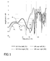
- four curves are depicted, each illustrating the sound pressure level in decibel (dB) over frequency which were measured at four different listening locations in the passenger compartment, namely near the head restraints of the two front and the two rear seats, while supplying an audio signal to the loudspeakers.
- the sound pressure level measured at listening locations in the front of the room and the sound pressure level measured at listening locations in the rear differ by up to 15 dB, depending on the applied frequency.
- the biggest gap between the SPL curves can typically be observed within a frequency range from approximately 40 to 90 Hertz which is part of the bass frequency range.
- Base frequency range is not a well-defined term but widely used in acoustics for low frequencies in the range from, for example, 0 to 80 Hertz, 0 to 100 Hertz or even 0 to 150 Hertz. Especially when using car sound systems with a subwoofer placed in the rear window shelf or in the rear trunk, an unfavourable distribution of sound pressure level within the listening room can be observed.
- the SPL maximum between 60 and 70 Hertz may likely be regarded as booming and unpleasant by rear passengers.
- the frequency range wherein a big discrepancy between the sound pressure levels in different listening locations - especially between listening locations in the front and in the rear of the car - can be observed depends on the dimensions of the listening room.
- FIG. 2 is a schematic side-view of a car.
- a half wavelength (denoted as ⁇ /2) fits lengthwise in the passenger compartment.
- FIG. 1 shows that, approximately at this frequency, there is a maximum SPL observable at the rear listening locations. This indicates that the superpositioning of several standing waves in longitudinal and lateral directions in the interior of the car (the listening room) may be responsible for the inhomogeneous SPL distribution in the listening room.
- Figure 3 illustrates a sample arrangement of listening positions FR, FL, RR, RL and loudspeakers throughout a small and reverberant listening room such as the passenger compartment of a motor vehicle.
- the present invention shall not be limited to automotive applications and is applicable to any listening room. Further, a person skilled in the art will understand that the present example can easily be adapted to consider more or less than four listening positions.
- the four listening positions FL, FR, RL, RR depicted in Fig. 3 represent the front left (FL), the front right (FR), the rear left (RL), and the rear right (RR) listening position in the passenger compartment of a motor vehicle.
- five loudspeakers LS 1 to LS 5 are arranged throughout the passenger compartment, such as a front left loudspeaker LS 1 , a front right loudspeaker LS 2 , a rear left loudspeaker LS 3 , a rear right loudspeaker LS 4 , and a rear center loudspeaker LS 5 (e.g. a sub-woofer).
- Phase filters in the audio channels supplying the loudspeakers LS 1 , LS 2 , ..., LS 5 may be employed to equalize the group delay response at a desired position within the listening room.
- a desired position may be a listening position or, in order to account for more than one listening position, a position between two or more listening positions.
- a mean group delay response which may be represented by the average of the four group delay responses observed at the four listening positions FL, FR, RL, RR, may be subjected to equalization.
- the group delay response subjected to equalization is generally denoted as ⁇ G ( ⁇ ), the corresponding transfer function (frequency response) as H( ⁇ ).
- the group delay response ⁇ G (( ⁇ ) may be the group delay response observable at a given position in the listening room or an average group delay response calculated from two or more group delay responses observable at respective (a priori known) listening positions.
- phase summands ⁇ i ( ⁇ ) as well as the group delay summands ⁇ Gi ( ⁇ ) can be easily derived from measured impulse responses defining the transfer characteristics from each loudspeaker to each considered listening position.
- the group delay ⁇ G ( ⁇ ) subjected to equalization may be the average of the group delays observable at each of the listening positions FL, FR, RL, RR which are ⁇ GFL ( ⁇ ), ⁇ GFR ( ⁇ ), ⁇ GRL ( ⁇ ), and ⁇ GRR ( ⁇ ) ; each of these group delays ⁇ GX ( ⁇ ) (X ⁇ ⁇ FL, FR, RL, RR ⁇ ) being the sum ⁇ GX-LS1 ( ⁇ ) + ⁇ GX-LS2 ( ⁇ ) + ⁇ GX-LS3 ( ⁇ ) + ⁇ GX-LS4 ( ⁇ ) + ⁇ GX-LS5 ( ⁇ ) of the group delays relating to the single loudspeakers LS 1 , LS 2 , ..., LS 5 .
- phase responses ⁇ i ( ⁇ ) in equation 6 may be the average of the phase responses ⁇ FL-LSi, ⁇ FR-LSi , ⁇ RL-LSi , and ⁇ RR-LSi observable at the respective listening positions FL, FR, RL, RR and relating to the loudspeaker LS i .
- the all-pass filters H APi ( ⁇ ) with the phase responses ⁇ API ( ⁇ ) can be regarded as group delay equalizing filters.
- of the all-pass filters is, of course,
- 1.
- H APi ( ⁇ ) cos ⁇ APi ⁇ + j ⁇ sin ⁇ APi ⁇ , wherein j is the square root of -1.
- the impulse response h A-Pi [k] has to be time-shifted and truncated when designed in the time domain.
- the transfer function H A-Pi ( ⁇ ) may be multiplied with a window function in order to achieve, in essence, the same result (see also Oppenheim, Schafer: "Design of FIR Filters by Windowing", in: Discrete-Time Signal Processing. 2nd Ed., section 7.2, Prentice Hall, 1999 ).
- the all pass filters are not designed using the mentioned classical approach but using an iterative optimization method as described below. It turned out to be beneficial if the all pass filter is designed such that the resulting group delay response is limited in accordance with a group delay constraint function defining a (frequency dependent) interval. That is, the group delay response of the resulting all pass filters (one all pass filter H APi associated with each loud speaker LS i ) stay within a range defined by constraint functions denotes as c L ( ⁇ ) and c U ( ⁇ ).
- Equation (7) The desired phase response is given by equation (7) and denoted as ⁇ APi ( ⁇ ) .
- constraint functions c U and c L are illustrates in FIG. 4 .
- shape of the constraint function e.g. for the upper group delay limit, dashed line in FIG. 4
- the FIR filter "bulk delay" illustrated in FIG. 4 corresponds to the half length of the all pass FIR filter.
- the all pass filter length K is 4096 taps and, consequently, the bulk delay is 2048 taps corresponding to 46.44 ms for a sample frequency of 44.1 kHz.
- constraint function C L ( ⁇ ) defining the lower limit is symmetrically to the function C U ( ⁇ ) with respect to the horizontal line representing the bulk delay.
- FIG. 4 The structure of the overall system is depicted in FIG. 4 .
- An all-pass filter is arranged in each audio channel (H AP1 , H AP2 , H AP3, H AP4 , and H AP5 ) upstream to each of the loudspeakers LS 1 , LS 2 , LS 3 , LS 4 , LS 5 , respectively.
- the power amplifiers have been omitted in the illustration, whereby the all-pass transfer functions H AP1 , H AP2, H AP3, H AP4, and H AP5 are designed as explained above to equalize a given group delay response associated with one or more listening positions to match a predefined target group delay response (e.g. a constant group delay).
- Additional linear (or constant) phase filters may be disposed in each audio channel for global level equalization in order to achieve a desired sound impression. These filters, of course, can be combined (i.e. convolved) with other filters already existing in the audio channel for other purposes.
- the system illustrated in Figure 4 is, as discussed above, employed for improving audio reproduction within a bass frequency range in a listening room.
- the listening room comprises at least one loudspeaker and at least one listening position.
- a group delay response to be equalized ⁇ G1 ( ⁇ ), ⁇ G2 ( ⁇ ), ⁇ G3 ( ⁇ ), ⁇ G4 ( ⁇ ), ⁇ G5 ( ⁇ )with respect to a pre-defined position in the listening room is associated with each loudspeaker LS 1 , LS 2 , LS 3 , LS 4 , LS 5 .
- This predefined listening position may be an arbitrary position in the listening room such as, for example, a position in the middle between the four listening positions (which is at equal distance to each listening position FL, FR, RL, RR).
- the predefined listening position may also be a "virtual" listening position for which the associated group delay responses to be equalized (one for each loudspeaker) is an average of the group delay responses associated with the actual listening positions FL, FR, RL, RR.
- each group delay response to be equalized ⁇ Gi ( ⁇ ) may be transformed into a respective phase response ⁇ i ( ⁇ ) .
- One group delay equalizing filter is arranged in the audio channel upstream to each loudspeaker.
- Each filter is an all-pass filter whose transfer characteristic is defined by its filter coefficients.
- the filter coefficients of each filter are set such that the resulting group delay response ⁇ Gi ( ⁇ ) matches a predefined target group delay response ⁇ GTarget ( ⁇ ).
- this equalization may be performed by setting the filter coefficients such that the phase response ⁇ i ( ⁇ ) (corresponding to the group delay response ⁇ Gi ( ⁇ ) matches a target phase response ⁇ Target ( ⁇ ) which represents the above-mentioned target group delay response ⁇ GTarget ( ⁇ ).
- the method used for improving audio reproduction within a bass frequency range in a listening room includes a step of providing, for each loudspeaker LS i , a group delay response ⁇ Gi( ⁇ ) to be equalized, whereby each group delay response ⁇ Gi ( ⁇ ) is associated with one pre-defined position within the listening room. As explained above this pre-defined position may be any real position in the listening room, as well as a "virtual" listening position when averaged group delay response (s) ⁇ Gi ( ⁇ ) are to be equalized.
- the method further includes a step of calculating filter coefficients for all-pass filter(s) H APi ( ⁇ ). One filter is arranged in a corresponding audio channel upstream of each loudspeaker LS i .
- the all-pass filter(s) H APi ( ⁇ ) each have a transfer characteristic such that the resulting group delay response(s) ⁇ Gi ( ⁇ ) match(es) a pre-defined target group delay response ⁇ GTarget ( ⁇ ) .
- the step of providing a group delay response ⁇ Gi ( ⁇ ) to be equalized may further include the step of providing, for each pair of listening position and loudspeaker X-LS i (X ⁇ ⁇ FL, FR, RL, RR ⁇ , i ⁇ ⁇ 1, 2, 3, 4,5 ⁇ ), a phase response ⁇ XLSi ( ⁇ ) that is representative of the phase transfer characteristics of an audio signal from the loudspeaker LS i to the corresponding listening position X.
- each phase response ⁇ X-LSi ( ⁇ ) is representative of a corresponding group delay response ⁇ GX-LSi ( ⁇ ).
- a group delay response ⁇ Gi ( ⁇ ) to be equalized for each loudspeaker LS i may be provided. This may include a weighted averaging as mentioned above.
- the resulting group delay equalizing filters may be convolved with a pre-defined global equalizing filter for adjusting the overall sound impression.
- the pre-defined global equalizing filter may have any desirable magnitude response and a constant or linear phase response.
Landscapes
- Physics & Mathematics (AREA)
- Engineering & Computer Science (AREA)
- Acoustics & Sound (AREA)
- Signal Processing (AREA)
- Stereophonic System (AREA)
- Circuit For Audible Band Transducer (AREA)
Abstract
Description
- The present invention relates to a method and a system for automatically equalizing the group delay in the low audio frequency (bass) range generated by an audio system, also referred to as "bass management" method or system.
- Until now it has been common practice to acoustically optimize dedicated systems, e.g. in motor vehicles, by hand. Although there have been major efforts to automate this manual process, these methods and systems have shown weaknesses in practice or are extremely complex and costly. In small, highly reflective areas, such as the interior of a car, minor improvements in the acoustics are achieved. In some cases, the results are even worse.
- Especially in the frequency range below approximately 100 to 150 Hertz, standing waves in the interior of small highly reflective rooms can cause very different sound pressure levels (SPL) in various listening locations, such as the two front seats and the two rear passenger's seats in a motor vehicle. These different sound pressure levels make the audio perception of a person dependent on his/her listening location. However, the fact that it is possible to achieve a good acoustic result even with simple means has been proven by the work of professional acousticians.
- A method is known which allows any acoustics to be modeled in virtually any area. However, this so-called wave-field synthesis requires very extensive resources such as computation power, memories, loudspeakers, amplifier channels, etc. This technique is thus not suitable for many applications for cost and feasibility reasons, especially in the automotive industry.
- Further, automatic bass management systems are known that aim to equalize and simultaneously maximize the sound pressure level in the bass frequency range at the listeners' positions within the listening room. However, the results have been assessed as insufficient in hearing tests, indicating that performing SPL equalization may be just one step in improving the quality of sound reproduction in the bass frequency level.
- There is a need for an automatic bass management that can adequately replace the previously used, complex process of manual equalizing carried out by experienced acousticians and that reliably improves the sound impression in the bass frequency range.
- A method for improving audio reproduction within a bass frequency range in a listening room is disclosed. The listening room includes at least one loudspeaker and at least one listening position. The method includes: providing, for each loudspeaker, a group delay response to be equalized associated with one pre-defined position within the listening room; calculating filter coefficients for all-pass filter(s) each arranged upstream to one corresponding loudspeaker, the all-pass filter(s) having a transfer characteristic such that the corresponding group delay response(s) match(es) a predefined target group delay response.
- The invention can be better understood referring to the following drawings and descriptions. In the figures like reference numerals designate corresponding parts. In the drawings:
- FIG. 1
- is a diagram illustrating the sound pressure level in decibel over frequency measured on four different listening locations in a passenger compartment of a car with an unmodified audio signal being supplied to the loudspeakers;
- FIG. 2
- is a schematic side view illustrating standing acoustic waves in the passenger compartment of a car which are responsible for large differences in sound pressure level (SPL) between the listening locations;
- FIG. 3
- is a schematic top view illustrating the arrangement of seating and thus listening positions as well as the arrangement of loudspeakers in a passenger compartment of a motor vehicle;
- FIG. 4
- illustrates an example of a group delay constraint function over frequency defining the fre- quency depending limits for the group delay of the sought all pass filter; and
- FIG. 5
- is a schematic top view illustrating the arrangement of the group delay equalizing filters in the audio channels upstream of the loudspeakers.
- While reproducing an audio signal by means of a loudspeaker or a set of loudspeakers in a car, measurements in the passenger compartment of the car yield considerably different results for the sound pressure level (SPL) present at different listening locations, even if the loudspeakers are symmetrically arranged throughout the car. The diagram of
FIG. 1 illustrates this effect. In the diagram, four curves are depicted, each illustrating the sound pressure level in decibel (dB) over frequency which were measured at four different listening locations in the passenger compartment, namely near the head restraints of the two front and the two rear seats, while supplying an audio signal to the loudspeakers. One can see that the sound pressure level measured at listening locations in the front of the room and the sound pressure level measured at listening locations in the rear differ by up to 15 dB, depending on the applied frequency. However, the biggest gap between the SPL curves can typically be observed within a frequency range from approximately 40 to 90 Hertz which is part of the bass frequency range. - "Bass frequency range" is not a well-defined term but widely used in acoustics for low frequencies in the range from, for example, 0 to 80 Hertz, 0 to 100 Hertz or even 0 to 150 Hertz. Especially when using car sound systems with a subwoofer placed in the rear window shelf or in the rear trunk, an unfavourable distribution of sound pressure level within the listening room can be observed. The SPL maximum between 60 and 70 Hertz (cf.
FIG. 1 ) may likely be regarded as booming and unpleasant by rear passengers. - The frequency range wherein a big discrepancy between the sound pressure levels in different listening locations - especially between listening locations in the front and in the rear of the car - can be observed depends on the dimensions of the listening room. The reason for this can be explained with reference to
FIG. 2 , which is a schematic side-view of a car. A half wavelength (denoted as λ/2) fits lengthwise in the passenger compartment. A typical length of λ/2 = 2.5 m yields a frequency of f = c/λ = 68 Hz when assuming a speed of sound of c = 340 m/s. It can be seen fromFIG. 1 that, approximately at this frequency, there is a maximum SPL observable at the rear listening locations. This indicates that the superpositioning of several standing waves in longitudinal and lateral directions in the interior of the car (the listening room) may be responsible for the inhomogeneous SPL distribution in the listening room. - Automatic bass management systems are known, for example, from the publications
EP 2 051 543 A1 andEP 2 043 384 A1 . Such systems aim to equalize and (as an option) simultaneously maximize the sound pressure level in the bass frequency range at the listeners' positions within the listening room. However, the resulting bass reproduction has been assessed as insufficient (i.e. as washed-out or flaccid) in hearing tests which indicates that performing SPL equalization may be just one step in improving the quality of sound reproduction in the bass frequency level. A novel bass management system described herein considers the group delay of reproduced audio signals in the bass frequency range. -
Figure 3 illustrates a sample arrangement of listening positions FR, FL, RR, RL and loudspeakers throughout a small and reverberant listening room such as the passenger compartment of a motor vehicle. However, the present invention shall not be limited to automotive applications and is applicable to any listening room. Further, a person skilled in the art will understand that the present example can easily be adapted to consider more or less than four listening positions. - The four listening positions FL, FR, RL, RR depicted in
Fig. 3 represent the front left (FL), the front right (FR), the rear left (RL), and the rear right (RR) listening position in the passenger compartment of a motor vehicle. In the present example five loudspeakers LS1 to LS5 are arranged throughout the passenger compartment, such as a front left loudspeaker LS1, a front right loudspeaker LS2, a rear left loudspeaker LS3, a rear right loudspeaker LS4, and a rear center loudspeaker LS5 (e.g. a sub-woofer). When supplying test signals of different frequencies (or a broad band test signal) to the loudspeakers LS1 to LS5, a resulting impulse response h[k], frequency response H((ω) (i.e. the transfer functions of magnitude |H(ω| and phase ϕ(ω)=arg{H(ω}) and group delay τG(ω) response can be observed at each listening position. Such methods of "system identification" are well known in the field of acoustics. The frequency response is the Fourier transform of the impulse response and may be approximated by the fast Fourier transform (FFT):
- Further, the group delay is defined as

- The frequency response Hx(ω) (with X ∈ {FL, FR, RL, RR}) observed at each listening position FL, FR, RL, RR is a superposition of the frequency responses resulting from each single loudspeaker LS1 to LS5, that is

wherein HX-LSi (ω) is the transfer function of a system describing the relation between an acoustic signal observable at the listening position X and a respective audio signal supplied to and radiated from loudspeaker LSi (seeFIG. 3 ). Analogously, the group delay response τGX((ω) observed at a listening position X can be regarded as the superposition of the components τ GX-LSi(ω) for i = 1, ..., 5 and X ∈ {FL, FR, RL, RR} in the present example
- From psycho-acoustical studies (see, for example, J. Blauert, P. Laws: Perceptibility of group delay distortions, in: J. Acoust. Soc. Am., Vol. 63, No. 5, 1978) it is known that group delay distortions which exceed a given frequency dependent threshold can be perceived by a human listener. Thus, by reducing group delay distortions, that is, by equalizing the group delay response within the bass frequency range, the quality of high fidelity audio reproduction may be improved.
- Phase filters (all-pass filters HAP1, HAP2, ..., HAP5, see
Fig. 5 ) in the audio channels supplying the loudspeakers LS1, LS2, ..., LS5 may be employed to equalize the group delay response at a desired position within the listening room. Such a desired position may be a listening position or, in order to account for more than one listening position, a position between two or more listening positions. Similarly, if the sound impression at more than one listening positions is to be improved a mean group delay response, which may be represented by the average of the four group delay responses observed at the four listening positions FL, FR, RL, RR, may be subjected to equalization. - For further discussion the group delay response subjected to equalization is generally denoted as τG(ω), the corresponding transfer function (frequency response) as H(ω). As mentioned above, the group delay response τ G((ω) may be the group delay response observable at a given position in the listening room or an average group delay response calculated from two or more group delay responses observable at respective (a priori known) listening positions.
- As stated in equation 4, the considered group delay response τ G(ω) may be decomposed to a number of summands

wherein the number of summands equals the number N of loudspeakers arranged in the listening room, each summand τ Gi(ω) corresponding to a defined loudspeaker LSi. The same decomposition can be done for the corresponding phase
wherein the phase response ϕ(ω) is the phase of the complex transfer function H (ω), that is ϕ (ω) =arg{H(ω)} . It should be noted that the phase summands ϕ i(ω), as well as the group delay summands τ Gi(ω), can be easily derived from measured impulse responses defining the transfer characteristics from each loudspeaker to each considered listening position. Just to give an example, the group delay τ G(ω) subjected to equalization may be the average of the group delays observable at each of the listening positions FL, FR, RL, RR which are τ GFL (ω), τ GFR (ω), τ GRL (ω), and τ GRR (ω) ; each of these group delays τ GX(ω) (X ∈ { FL, FR, RL, RR } ) being the sum τ GX-LS1 (ω) + τ GX-LS2 (ω) + τ GX-LS3 (ω) + τ GX-LS4(ω) + τ GX-LS5(ω) of the group delays relating to the single loudspeakers LS1, LS2, ..., LS5. Analogously, the phase responses ϕ i(ω) in equation 6 may be the average of the phase responses ϕ FL-LSi, ϕ FR-LSi, ϕ RL-LSi, and ϕ RR-LSi observable at the respective listening positions FL, FR, RL, RR and relating to the loudspeaker LSi. - For group delay equalization all-pass filters arranged in each audio channel supplying a loudspeaker LSi are designed to have such a phase response ϕ API (ω) that each resulting group delay responses τ Gi (ω) (with i = 1, 2, ...) in
equation 5 matches a predefined target (i.e. desired) group delay response τ TARGET (ω). Thus, the all-pass filters HAPi (ω) with the phase responses ϕ API (ω) can be regarded as group delay equalizing filters. The target group delay response τ TARGET (ω) is directly related to a target phase response ϕ TARGET (ω), and consequently the sought phase response ϕ APi(ω) of the all-pass filter arranged in the audio channel upstream to a loudspeaker LSi is
whereby N is the number of loudspeakers (N = 5 in the example ofFIG. 3 ). The magnitude response | HAPi (ω) | of the all-pass filters is, of course, | HAPi (ω) | = 1. There are many possibilities known to a person skilled in the art to calculate the corresponding all-pass impulse response (i.e. the FIR filter coefficients) hAPi [k] from the phase response ϕ API (ω) of equation 7. One example is given below. - The real and the imaginary part of the complex all-pass transfer function is set as defined below:


- The complex all-pass transfer function HAPi(ω) can thus be written as

wherein j is the square root of -1. The phase values ϕ APi(ω) for frequencies above the base frequency range (i.e. for angular frequencies ω > 2π·100 Hz or ω > 2π·150 Hz) are set to zero in order to avoid broad band phase distortions outside the bass frequency range, i.e.
- The transfer function HAPi(ω) of
equation 10 may be transformed into the (discrete) time domain by means of the inverse FFT. Before transformation into the time domain one has to ensure that ϕ APi (ω) is symmetric, i.e.

in order to obtain a real value impulse response hAPi [k]. In general, the resulting all-pass filter impulse response hA-Pi [k] will be acausal. In order to obtain a causal filter with an finite impulse response, the impulse response hA-Pi [k] has to be time-shifted and truncated when designed in the time domain. Alternatively, the transfer function HA-Pi (ω) may be multiplied with a window function in order to achieve, in essence, the same result (see also Oppenheim, Schafer: "Design of FIR Filters by Windowing", in: Discrete-Time Signal Processing. 2nd Ed., section 7.2, Prentice Hall, 1999). - However, sound tests yielded that all pass filters (i.e. phase equalizing filters) designed using classical FIR filter design approaches as mentioned above did not bring the desired improvement of audio quality. Undesired audible artifacts deteriorate high fidelity sound reproduction. This artifacts are a consequence of a significant pre-ringing the all-pass filters may exhibit when designed using standard design approaches. It has been found that an novel FIR all pass filter design method can resolve the mentioned problem and significantly enhance the quality of audio reproduction, in particular in the bass frequency range.
- In accordance with one example of the present invention the all pass filters are not designed using the mentioned classical approach but using an iterative optimization method as described below. It turned out to be beneficial if the all pass filter is designed such that the resulting group delay response is limited in accordance with a group delay constraint function defining a (frequency dependent) interval. That is, the group delay response of the resulting all pass filters (one all pass filter HAPi associated with each loud speaker LSi) stay within a range defined by constraint functions denotes as cL(ω) and cU(ω).
- The desired phase response is given by equation (7) and denoted as ϕAPi (ω) . At the beginning of the iterative filter design procedure, the respective all pass filter HAPi(ω) is initialized, for example as HAPi (ω)=exp (0) =1. Further, the following minimization task (for minimizing the error function E) is solved:

considering the side conditions

- Any common minimum search method may be used. In tests the the Nelder-Mead Simplex Method has been used as provided by the Matlab(tm) function "fminsearch", for finding the optimum all pass filter coefficients HApiOPT (ω).
- It should be noted, that the norm ∥·∥ used in eq. (14) to calculate the error to be minimized may be chosen so as to yield a quadratic error, that is

where K is the number of discrete frequency values ω k and thus the length of the FIR all pass filter, e.g. K=4096. - One example of the constraint functions cU and cL is illustrates in
FIG. 4 . Generally, the shape of the constraint function (e.g. for the upper group delay limit, dashed line inFIG. 4 ) can be described as an exponentially decaying curve, such as
whereby a, p, and b are constant parameters, parameter b defining the asymptote. The FIR filter "bulk delay" illustrated inFIG. 4 corresponds to the half length of the all pass FIR filter. In the present example the all pass filter length K is 4096 taps and, consequently, the bulk delay is 2048 taps corresponding to 46.44 ms for a sample frequency of 44.1 kHz. In the example ofFig. 4 the constraint function C(ω) defining the upper group delay limit is
- It should be noted that the constraint function CL(ω) defining the lower limit is symmetrically to the function CU(ω) with respect to the horizontal line representing the bulk delay.
- The structure of the overall system is depicted in
FIG. 4 . An all-pass filter is arranged in each audio channel (HAP1, HAP2, HAP3, HAP4, and HAP5) upstream to each of the loudspeakers LS1, LS2, LS3, LS4, LS5, respectively. For the sake of simplicity the power amplifiers have been omitted in the illustration, whereby the all-pass transfer functions HAP1, HAP2, HAP3, HAP4, and HAP5 are designed as explained above to equalize a given group delay response associated with one or more listening positions to match a predefined target group delay response (e.g. a constant group delay). Additional linear (or constant) phase filters may be disposed in each audio channel for global level equalization in order to achieve a desired sound impression. These filters, of course, can be combined (i.e. convolved) with other filters already existing in the audio channel for other purposes. - Below some important aspects of the system shown in
Fig. 5 as well as the corresponding equalizing method are summarized. The system illustrated inFigure 4 is, as discussed above, employed for improving audio reproduction within a bass frequency range in a listening room. The listening room comprises at least one loudspeaker and at least one listening position. In the present example there are four listening positions FL, FR, RL, RR and five loudspeakers LSi (i ∈ {1, 2, 3, 4, 5}) provided in a passenger compartment of a motor vehicle. A group delay response to be equalized τ G1 (ω), τ G2 (ω), τ G3(ω), τ G4(ω), τ G5 (ω)with respect to a pre-defined position in the listening room is associated with each loudspeaker LS1, LS2, LS3, LS4, LS5. This predefined listening position may be an arbitrary position in the listening room such as, for example, a position in the middle between the four listening positions (which is at equal distance to each listening position FL, FR, RL, RR). However, the predefined listening position may also be a "virtual" listening position for which the associated group delay responses to be equalized (one for each loudspeaker) is an average of the group delay responses associated with the actual listening positions FL, FR, RL, RR. For example, the group delay response to be equalized may be defined, for loudspeaker LSi, as
whereby τ GX-LSi (ω) with X ∈ {FL, FR, RL, RR} represents the group delay response associated with listening position X and loudspeaker LSi. As discussed above each group delay response to be equalized τ Gi (ω) may be transformed into a respective phase response ϕ i(ω) . - One group delay equalizing filter is arranged in the audio channel upstream to each loudspeaker. Each filter is an all-pass filter whose transfer characteristic is defined by its filter coefficients. The filter coefficients of each filter are set such that the resulting group delay response τ Gi (ω) matches a predefined target group delay response τ GTarget (ω). In practice this equalization may be performed by setting the filter coefficients such that the phase response ϕi(ω) (corresponding to the group delay response τGi (ω) matches a target phase response ϕTarget (ω) which represents the above-mentioned target group delay response τGTarget (ω).
- The method used for improving audio reproduction within a bass frequency range in a listening room includes a step of providing, for each loudspeaker LSi, a group delay response τGi(ω) to be equalized, whereby each group delay response τGi(ω) is associated with one pre-defined position within the listening room. As explained above this pre-defined position may be any real position in the listening room, as well as a "virtual" listening position when averaged group delay response (s) τ Gi(ω) are to be equalized. The method further includes a step of calculating filter coefficients for all-pass filter(s) HAPi (ω). One filter is arranged in a corresponding audio channel upstream of each loudspeaker LSi. The all-pass filter(s) HAPi (ω) each have a transfer characteristic such that the resulting group delay response(s) τ Gi(ω) match(es) a pre-defined target group delay response τ GTarget (ω) .
- As mentioned above, the equalizing may be performed by setting the phase responses ϕ APi = arg{HAPi} of the filter(s) so that the resulting phase response ϕ i (ω) (corresponding to the group delay response τ Gi(ω) ) matches a pre-defined target phase response ϕ Target (ω) (corresponding to the target group delay response τ GTarget (ω) ) .
- The step of providing a group delay response τ Gi (ω) to be equalized may further include the step of providing, for each pair of listening position and loudspeaker X-LSi (X ∈ {FL, FR, RL, RR}, i ∈ {1, 2, 3, 4,5}), a phase response ϕ XLSi(ω) that is representative of the phase transfer characteristics of an audio signal from the loudspeaker LSi to the corresponding listening position X. Thereby, each phase response ϕ X-LSi (ω) is representative of a corresponding group delay response τ GX-LSi (ω). Then, dependent on the group delay response (s) τ GX-LSi (ω), a group delay response τ Gi (ω) to be equalized for each loudspeaker LSi may be provided. This may include a weighted averaging as mentioned above.
- Finally, the above mentioned step of calculating filter coefficients may include providing a target phase response ϕ Target (ω) representative of the target group delay response τ GTarget (ω), further, calculating, for each loudspeaker, the frequency dependent phase difference ϕ Api(ω) = ϕ i (ω)-ϕ Target (ω) between a phase response representative for the group delay response to be equalized and the target phase response ϕ Target(ω), and, finally, calculating, for each loudspeaker, all-pass filter coefficients, using the calculated phase difference (s) (ϕ APi(ω)) as the desired filter phase response(s) in the filter design.
- The resulting group delay equalizing filters may be convolved with a pre-defined global equalizing filter for adjusting the overall sound impression. The pre-defined global equalizing filter may have any desirable magnitude response and a constant or linear phase response.
- Although the present invention and its advantages have been described in detail, it should be understood that various changes, substitutions, and alterations can be made herein without departing from the spirit and scope of the invention as defined by the appended claims.
- Moreover, the scope of the present application is not intended to be limited to the particular embodiments of the process, machine, manufacture, composition of matter, means, methods, and steps described in the specification. As one of ordinary skill in the art will readily appreciate from the disclosure of the present invention, processes, machines, manufacture, compositions of matter, means, methods, or steps, presently existing or later to be developed, that perform substantially the same function or achieve substantially the same result as the corresponding embodiments described herein may be utilized according to the present invention. Accordingly, the appended claims are intended to include within their scope such processes, machines, manufacture, compositions of matter, means, methods, or steps.
Claims (16)
- An all-pass filter design method for improving audio reproduction within a bass frequency range in a listening room comprising at least one loudspeaker and at least one listening position, the method comprises:providing, for each loudspeaker, a group delay response to be equalized and associated with one pre-defined position in the listening room;calculating filter coefficients for all-pass filter(s) each arranged upstream to one corresponding loudspeaker, the all-pass filter(s) having a transfer characteristic such that the corresponding group delay response(s) match(es) a predefined target group delay response.
- The method of claim 1, where the step of calculating filter coefficients comprises for each all pass filter associated with one respective loudspeaker:providing a frequency dependent group delay constraint defining a finite range which confines the group delay response of the all pass filter;iteratively calculating updated filter coefficients such that an error norm assumes a minimum while complying with the group delay constraint, the error norm representing the deviation of the group delay response of the respective all pass filter from the corresponding target group delay response.
- The method of claim 2, where the frequency dependent group delay constraint defines a frequency dependent interval exponentially decaying with increasing frequency.
- The method of claim 3, where the interval being arranged symmetrically around an all pass bulk delay corresponding to the half filter length.
- The method of claim 3 or 4, where the interval asymptotically approaches a constant interval with increasing frequencies.
- The method of one of the claims 3 to 5, where the interval is confined by an upper limit cU (ω) = a · exp (ω/p)+b and a lower limit cL(ω) = -a· exp (ω/p) +b,
thereby ω being the frequency in rad/s, b being a constant parameter representing an all pass bulk delay, and a and p being constant parameters describing the exponential narrowing of the interval. - The method of one of the claims 1 to 6, where the step of providing a group delay response to be equalized comprises:providing, for each pair of listening position and loudspeaker, a phase response that is representative of the phase transfer characteristics of an audio signal from the loudspeaker to the corresponding listening position, each phase response being representative of a corresponding group delay response;providing, dependent on the group delay response(s), a group delay response to be equalized for each loudspeaker.
- The method of one of the claims 1 to 7, where the step of providing a group delay response to be equalized for each loudspeaker further comprises:calculating, for each loudspeaker, a weighted average of the phase responses, which are associated with the considered loudspeaker, over all considered listening positions, the resulting average phase response(s) being representative for the group delay response(s) to be equalized.
- The method of one of the claims 1 to 8 where the step of calculating filter coefficients comprises:providing a target phase response being representative of the target group delay response;calculating, for each loudspeaker, the frequency dependent phase difference between a phase response being representative for the group delay response to be equalized and the target phase response,calculating, for each loudspeaker, all-pass filter coefficients, using the calculated phase difference(s) as desired filter phase response(s).
- The method of one of the claims 1 to 9 further comprising:convolving each calculated sequence of all-pass filter coefficients with a sequence of filter coefficients of an pre-defined global equalizing filter.
- The method of claim 10 wherein the pre-defined global equalizing filter is either a linear phase or a constant phase filter with a predefined magnitude response.
- A system for improving audio reproduction within a bass frequency range in a listening room comprising at least one loudspeaker and at least one listening position, a group delay response to be equalized with respect to a predefined position within the listening room being associated with each loudspeaker, the system comprises:a group delay equalizing filter arranged upstream to each loudspeaker, each filter being an all-pass filter whose transfer characteristics is defined by its filter coefficients,wherein the filter coefficients of each filter are set such that the resulting group delay response matches a predefined target group delay response.
- The system of claim 12, where the filter coefficients have a group delay response being confined by a frequency dependent group delay constraint that defines a frequency dependent interval exponentially decaying with increasing frequency
- The system of claim 11 or 12, wherein, for each loudspeaker, the group delay response to be equalized corresponds to a respective phase response which is calculated dependent on the phase characteristics associated with each pair of listening position and loudspeaker.
- The system of claim 14, wherein, for each loudspeaker, the group delay response to be equalized corresponds to a respective phase response which is a weighted average of the phase responses associated with each pair of listening position and loudspeaker.
- A system for improving audio reproduction within a bass frequency range in a listening room comprising at least one loudspeaker and at least one all pass FIR filter connected upstream to each loudspeaker, the FIR filters being designed in accordance with one of the methods of claims 1 to 10.
Priority Applications (1)
| Application Number | Priority Date | Filing Date | Title |
|---|---|---|---|
| EP10194206.8A EP2357847B1 (en) | 2009-12-22 | 2010-12-08 | Group-delay based bass management |
Applications Claiming Priority (2)
| Application Number | Priority Date | Filing Date | Title |
|---|---|---|---|
| EP09180411A EP2357846A1 (en) | 2009-12-22 | 2009-12-22 | Group-delay based bass management |
| EP10194206.8A EP2357847B1 (en) | 2009-12-22 | 2010-12-08 | Group-delay based bass management |
Publications (3)
| Publication Number | Publication Date |
|---|---|
| EP2357847A2 true EP2357847A2 (en) | 2011-08-17 |
| EP2357847A3 EP2357847A3 (en) | 2011-12-28 |
| EP2357847B1 EP2357847B1 (en) | 2016-08-10 |
Family
ID=42133680
Family Applications (2)
| Application Number | Title | Priority Date | Filing Date |
|---|---|---|---|
| EP09180411A Withdrawn EP2357846A1 (en) | 2009-12-22 | 2009-12-22 | Group-delay based bass management |
| EP10194206.8A Active EP2357847B1 (en) | 2009-12-22 | 2010-12-08 | Group-delay based bass management |
Family Applications Before (1)
| Application Number | Title | Priority Date | Filing Date |
|---|---|---|---|
| EP09180411A Withdrawn EP2357846A1 (en) | 2009-12-22 | 2009-12-22 | Group-delay based bass management |
Country Status (3)
| Country | Link |
|---|---|
| US (1) | US9191766B2 (en) |
| EP (2) | EP2357846A1 (en) |
| CN (1) | CN102104816B (en) |
Cited By (2)
| Publication number | Priority date | Publication date | Assignee | Title |
|---|---|---|---|---|
| WO2020052756A1 (en) * | 2018-09-12 | 2020-03-19 | Ask Industries Gmbh | Method for operating an in-motor-vehicle audio output device |
| WO2023088842A1 (en) | 2021-11-17 | 2023-05-25 | Rocket Science Ag | Method for eliminating room modes, and digital signal processor and loudspeaker therefor |
Families Citing this family (15)
| Publication number | Priority date | Publication date | Assignee | Title |
|---|---|---|---|---|
| EP2856645A2 (en) * | 2012-05-31 | 2015-04-08 | Dolby Laboratories Licensing Corporation | Low latency and low complexity phase shift network |
| US9467111B2 (en) * | 2012-06-29 | 2016-10-11 | Audyssey Laboratories | Operator adjustable full-bandwidth audio spectral shifting control with a simple listener interface |
| DE102013105375A1 (en) * | 2013-05-24 | 2014-11-27 | Fraunhofer-Gesellschaft zur Förderung der angewandten Forschung e.V. | A sound signal generator, method and computer program for providing a sound signal |
| GB2541639B (en) * | 2015-06-15 | 2019-06-12 | Meridian Audio Ltd | Asymmetric stereophonic bass compensation |
| CN105262503B (en) * | 2015-07-16 | 2018-04-24 | 中国电子科技集团公司第四十一研究所 | A kind of multidiameter delay generation device and method based on group delay calibration |
| WO2017074232A1 (en) * | 2015-10-30 | 2017-05-04 | Dirac Research Ab | Reducing the phase difference between audio channels at multiple spatial positions |
| US10075789B2 (en) * | 2016-10-11 | 2018-09-11 | Dts, Inc. | Gain phase equalization (GPEQ) filter and tuning methods for asymmetric transaural audio reproduction |
| US10893361B2 (en) * | 2018-01-04 | 2021-01-12 | Harman Becker Automotive Systems Gmbh | Low frequency sound field in a listening environment |
| CN109089203B (en) * | 2018-09-17 | 2020-10-02 | 中科上声(苏州)电子有限公司 | Multi-channel signal conversion method of automobile sound system and automobile sound system |
| EP3900394A1 (en) * | 2018-12-21 | 2021-10-27 | FRAUNHOFER-GESELLSCHAFT zur Förderung der angewandten Forschung e.V. | Sound reproduction/simulation system and method for simulating a sound reproduction |
| TWI866996B (en) | 2019-06-26 | 2024-12-21 | 美商杜拜研究特許公司 | Low latency audio filterbank with improved frequency resolution |
| US12289594B2 (en) | 2019-09-03 | 2025-04-29 | Dolby Laboratories Licensing Corporation | Audio filterbank with decorrelating components |
| CN111526455A (en) * | 2020-05-21 | 2020-08-11 | 菁音电子科技(上海)有限公司 | Correction enhancement method and system for vehicle-mounted sound |
| EP4322554A1 (en) * | 2022-08-11 | 2024-02-14 | Bang & Olufsen A/S | Method and system for managing the low frequency content in a loudspeaker system |
| CN117676418B (en) * | 2023-12-06 | 2024-05-24 | 广州番禺职业技术学院 | A sound field equalization method and system for hybrid phase system |
Citations (1)
| Publication number | Priority date | Publication date | Assignee | Title |
|---|---|---|---|---|
| EP2043384A1 (en) | 2007-09-27 | 2009-04-01 | Harman Becker Automotive Systems GmbH | Adaptive bass management |
Family Cites Families (15)
| Publication number | Priority date | Publication date | Assignee | Title |
|---|---|---|---|---|
| US4771466A (en) * | 1983-10-07 | 1988-09-13 | Modafferi Acoustical Systems, Ltd. | Multidriver loudspeaker apparatus with improved crossover filter circuits |
| JPH03216097A (en) * | 1990-01-22 | 1991-09-24 | Sony Corp | Speaker system |
| GB9026906D0 (en) * | 1990-12-11 | 1991-01-30 | B & W Loudspeakers | Compensating filters |
| US5325436A (en) * | 1993-06-30 | 1994-06-28 | House Ear Institute | Method of signal processing for maintaining directional hearing with hearing aids |
| US6760451B1 (en) * | 1993-08-03 | 2004-07-06 | Peter Graham Craven | Compensating filters |
| US7277554B2 (en) * | 2001-08-08 | 2007-10-02 | Gn Resound North America Corporation | Dynamic range compression using digital frequency warping |
| US7567675B2 (en) * | 2002-06-21 | 2009-07-28 | Audyssey Laboratories, Inc. | System and method for automatic multiple listener room acoustic correction with low filter orders |
| WO2004002192A1 (en) * | 2002-06-21 | 2003-12-31 | University Of Southern California | System and method for automatic room acoustic correction |
| US8280076B2 (en) * | 2003-08-04 | 2012-10-02 | Harman International Industries, Incorporated | System and method for audio system configuration |
| US7720237B2 (en) * | 2004-09-07 | 2010-05-18 | Audyssey Laboratories, Inc. | Phase equalization for multi-channel loudspeaker-room responses |
| US8355510B2 (en) * | 2004-12-30 | 2013-01-15 | Harman International Industries, Incorporated | Reduced latency low frequency equalization system |
| US9008331B2 (en) * | 2004-12-30 | 2015-04-14 | Harman International Industries, Incorporated | Equalization system to improve the quality of bass sounds within a listening area |
| JP2009530915A (en) * | 2006-03-15 | 2009-08-27 | ドルビー・ラボラトリーズ・ライセンシング・コーポレーション | 3D sound image |
| US8194885B2 (en) * | 2008-03-20 | 2012-06-05 | Dirac Research Ab | Spatially robust audio precompensation |
| JP5421376B2 (en) * | 2009-05-18 | 2014-02-19 | ハーマン インターナショナル インダストリーズ インコーポレイテッド | Audio system optimized for efficiency |
-
2009
- 2009-12-22 EP EP09180411A patent/EP2357846A1/en not_active Withdrawn
-
2010
- 2010-12-08 EP EP10194206.8A patent/EP2357847B1/en active Active
- 2010-12-21 US US12/974,933 patent/US9191766B2/en active Active
- 2010-12-22 CN CN201010601232.4A patent/CN102104816B/en active Active
Patent Citations (2)
| Publication number | Priority date | Publication date | Assignee | Title |
|---|---|---|---|---|
| EP2043384A1 (en) | 2007-09-27 | 2009-04-01 | Harman Becker Automotive Systems GmbH | Adaptive bass management |
| EP2051543A1 (en) | 2007-09-27 | 2009-04-22 | Harman/Becker Automotive Systems GmbH | Automatic bass management |
Non-Patent Citations (1)
| Title |
|---|
| J. BLAUERT, P.: "Laws: Perceptibility of group delay distortions", J. ACOUST. SOC. AM., vol. 63, no. 5, 1978 |
Cited By (4)
| Publication number | Priority date | Publication date | Assignee | Title |
|---|---|---|---|---|
| WO2020052756A1 (en) * | 2018-09-12 | 2020-03-19 | Ask Industries Gmbh | Method for operating an in-motor-vehicle audio output device |
| CN112703749A (en) * | 2018-09-12 | 2021-04-23 | Ask工业有限公司 | Method for operating an audio output device on a motor vehicle |
| CN112703749B (en) * | 2018-09-12 | 2023-08-25 | Ask工业有限公司 | Method for operating an audio output device in a motor vehicle |
| WO2023088842A1 (en) | 2021-11-17 | 2023-05-25 | Rocket Science Ag | Method for eliminating room modes, and digital signal processor and loudspeaker therefor |
Also Published As
| Publication number | Publication date |
|---|---|
| US9191766B2 (en) | 2015-11-17 |
| CN102104816A (en) | 2011-06-22 |
| US20110150241A1 (en) | 2011-06-23 |
| EP2357846A1 (en) | 2011-08-17 |
| EP2357847B1 (en) | 2016-08-10 |
| EP2357847A3 (en) | 2011-12-28 |
| CN102104816B (en) | 2016-01-13 |
Similar Documents
| Publication | Publication Date | Title |
|---|---|---|
| EP2357847B1 (en) | Group-delay based bass management | |
| CN102055425B (en) | Audio system phase equalizion | |
| EP1843635B1 (en) | Method for automatically equalizing a sound system | |
| EP2806664B1 (en) | Sound system for establishing a sound zone | |
| EP2051543B1 (en) | Automatic bass management | |
| US20100208900A1 (en) | Method for the sound processing of a stereophonic signal inside a motor vehicle and motor vehicle implementing said method | |
| EP2930957B1 (en) | Sound wave field generation | |
| EP2930954B1 (en) | Adaptive filtering | |
| EP2930953B1 (en) | Sound wave field generation | |
| EP2190221A1 (en) | Audio system | |
| EP2930956B1 (en) | Adaptive filtering | |
| EP2930955B1 (en) | Adaptive filtering | |
| EP1843636B1 (en) | Method for automatically equalizing a sound system | |
| Zhang et al. | Hybrid multi-channel system in automotive audio |
Legal Events
| Date | Code | Title | Description |
|---|---|---|---|
| PUAI | Public reference made under article 153(3) epc to a published international application that has entered the european phase |
Free format text: ORIGINAL CODE: 0009012 |
|
| AK | Designated contracting states |
Kind code of ref document: A2 Designated state(s): AL AT BE BG CH CY CZ DE DK EE ES FI FR GB GR HR HU IE IS IT LI LT LU LV MC MK MT NL NO PL PT RO RS SE SI SK SM TR |
|
| AX | Request for extension of the european patent |
Extension state: BA ME |
|
| PUAL | Search report despatched |
Free format text: ORIGINAL CODE: 0009013 |
|
| AK | Designated contracting states |
Kind code of ref document: A3 Designated state(s): AL AT BE BG CH CY CZ DE DK EE ES FI FR GB GR HR HU IE IS IT LI LT LU LV MC MK MT NL NO PL PT RO RS SE SI SK SM TR |
|
| AX | Request for extension of the european patent |
Extension state: BA ME |
|
| RIC1 | Information provided on ipc code assigned before grant |
Ipc: H04S 7/00 20060101ALI20111124BHEP Ipc: H04R 3/04 20060101AFI20111124BHEP |
|
| 17P | Request for examination filed |
Effective date: 20120627 |
|
| 17Q | First examination report despatched |
Effective date: 20150213 |
|
| GRAP | Despatch of communication of intention to grant a patent |
Free format text: ORIGINAL CODE: EPIDOSNIGR1 |
|
| INTG | Intention to grant announced |
Effective date: 20160125 |
|
| GRAS | Grant fee paid |
Free format text: ORIGINAL CODE: EPIDOSNIGR3 |
|
| GRAA | (expected) grant |
Free format text: ORIGINAL CODE: 0009210 |
|
| AK | Designated contracting states |
Kind code of ref document: B1 Designated state(s): AL AT BE BG CH CY CZ DE DK EE ES FI FR GB GR HR HU IE IS IT LI LT LU LV MC MK MT NL NO PL PT RO RS SE SI SK SM TR |
|
| REG | Reference to a national code |
Ref country code: GB Ref legal event code: FG4D |
|
| REG | Reference to a national code |
Ref country code: CH Ref legal event code: EP Ref country code: AT Ref legal event code: REF Ref document number: 820008 Country of ref document: AT Kind code of ref document: T Effective date: 20160815 |
|
| REG | Reference to a national code |
Ref country code: IE Ref legal event code: FG4D |
|
| REG | Reference to a national code |
Ref country code: DE Ref legal event code: R096 Ref document number: 602010035306 Country of ref document: DE |
|
| REG | Reference to a national code |
Ref country code: LT Ref legal event code: MG4D |
|
| REG | Reference to a national code |
Ref country code: NL Ref legal event code: MP Effective date: 20160810 |
|
| REG | Reference to a national code |
Ref country code: AT Ref legal event code: MK05 Ref document number: 820008 Country of ref document: AT Kind code of ref document: T Effective date: 20160810 |
|
| PG25 | Lapsed in a contracting state [announced via postgrant information from national office to epo] |
Ref country code: NO Free format text: LAPSE BECAUSE OF FAILURE TO SUBMIT A TRANSLATION OF THE DESCRIPTION OR TO PAY THE FEE WITHIN THE PRESCRIBED TIME-LIMIT Effective date: 20161110 Ref country code: HR Free format text: LAPSE BECAUSE OF FAILURE TO SUBMIT A TRANSLATION OF THE DESCRIPTION OR TO PAY THE FEE WITHIN THE PRESCRIBED TIME-LIMIT Effective date: 20160810 Ref country code: RS Free format text: LAPSE BECAUSE OF FAILURE TO SUBMIT A TRANSLATION OF THE DESCRIPTION OR TO PAY THE FEE WITHIN THE PRESCRIBED TIME-LIMIT Effective date: 20160810 Ref country code: LT Free format text: LAPSE BECAUSE OF FAILURE TO SUBMIT A TRANSLATION OF THE DESCRIPTION OR TO PAY THE FEE WITHIN THE PRESCRIBED TIME-LIMIT Effective date: 20160810 Ref country code: FI Free format text: LAPSE BECAUSE OF FAILURE TO SUBMIT A TRANSLATION OF THE DESCRIPTION OR TO PAY THE FEE WITHIN THE PRESCRIBED TIME-LIMIT Effective date: 20160810 Ref country code: IT Free format text: LAPSE BECAUSE OF FAILURE TO SUBMIT A TRANSLATION OF THE DESCRIPTION OR TO PAY THE FEE WITHIN THE PRESCRIBED TIME-LIMIT Effective date: 20160810 Ref country code: IS Free format text: LAPSE BECAUSE OF FAILURE TO SUBMIT A TRANSLATION OF THE DESCRIPTION OR TO PAY THE FEE WITHIN THE PRESCRIBED TIME-LIMIT Effective date: 20161210 Ref country code: NL Free format text: LAPSE BECAUSE OF FAILURE TO SUBMIT A TRANSLATION OF THE DESCRIPTION OR TO PAY THE FEE WITHIN THE PRESCRIBED TIME-LIMIT Effective date: 20160810 |
|
| PG25 | Lapsed in a contracting state [announced via postgrant information from national office to epo] |
Ref country code: SE Free format text: LAPSE BECAUSE OF FAILURE TO SUBMIT A TRANSLATION OF THE DESCRIPTION OR TO PAY THE FEE WITHIN THE PRESCRIBED TIME-LIMIT Effective date: 20160810 Ref country code: GR Free format text: LAPSE BECAUSE OF FAILURE TO SUBMIT A TRANSLATION OF THE DESCRIPTION OR TO PAY THE FEE WITHIN THE PRESCRIBED TIME-LIMIT Effective date: 20161111 Ref country code: ES Free format text: LAPSE BECAUSE OF FAILURE TO SUBMIT A TRANSLATION OF THE DESCRIPTION OR TO PAY THE FEE WITHIN THE PRESCRIBED TIME-LIMIT Effective date: 20160810 Ref country code: LV Free format text: LAPSE BECAUSE OF FAILURE TO SUBMIT A TRANSLATION OF THE DESCRIPTION OR TO PAY THE FEE WITHIN THE PRESCRIBED TIME-LIMIT Effective date: 20160810 Ref country code: PT Free format text: LAPSE BECAUSE OF FAILURE TO SUBMIT A TRANSLATION OF THE DESCRIPTION OR TO PAY THE FEE WITHIN THE PRESCRIBED TIME-LIMIT Effective date: 20161212 Ref country code: PL Free format text: LAPSE BECAUSE OF FAILURE TO SUBMIT A TRANSLATION OF THE DESCRIPTION OR TO PAY THE FEE WITHIN THE PRESCRIBED TIME-LIMIT Effective date: 20160810 Ref country code: AT Free format text: LAPSE BECAUSE OF FAILURE TO SUBMIT A TRANSLATION OF THE DESCRIPTION OR TO PAY THE FEE WITHIN THE PRESCRIBED TIME-LIMIT Effective date: 20160810 |
|
| PG25 | Lapsed in a contracting state [announced via postgrant information from national office to epo] |
Ref country code: EE Free format text: LAPSE BECAUSE OF FAILURE TO SUBMIT A TRANSLATION OF THE DESCRIPTION OR TO PAY THE FEE WITHIN THE PRESCRIBED TIME-LIMIT Effective date: 20160810 Ref country code: RO Free format text: LAPSE BECAUSE OF FAILURE TO SUBMIT A TRANSLATION OF THE DESCRIPTION OR TO PAY THE FEE WITHIN THE PRESCRIBED TIME-LIMIT Effective date: 20160810 |
|
| REG | Reference to a national code |
Ref country code: DE Ref legal event code: R097 Ref document number: 602010035306 Country of ref document: DE |
|
| PG25 | Lapsed in a contracting state [announced via postgrant information from national office to epo] |
Ref country code: SM Free format text: LAPSE BECAUSE OF FAILURE TO SUBMIT A TRANSLATION OF THE DESCRIPTION OR TO PAY THE FEE WITHIN THE PRESCRIBED TIME-LIMIT Effective date: 20160810 Ref country code: BE Free format text: LAPSE BECAUSE OF FAILURE TO SUBMIT A TRANSLATION OF THE DESCRIPTION OR TO PAY THE FEE WITHIN THE PRESCRIBED TIME-LIMIT Effective date: 20160810 Ref country code: DK Free format text: LAPSE BECAUSE OF FAILURE TO SUBMIT A TRANSLATION OF THE DESCRIPTION OR TO PAY THE FEE WITHIN THE PRESCRIBED TIME-LIMIT Effective date: 20160810 Ref country code: SK Free format text: LAPSE BECAUSE OF FAILURE TO SUBMIT A TRANSLATION OF THE DESCRIPTION OR TO PAY THE FEE WITHIN THE PRESCRIBED TIME-LIMIT Effective date: 20160810 Ref country code: CZ Free format text: LAPSE BECAUSE OF FAILURE TO SUBMIT A TRANSLATION OF THE DESCRIPTION OR TO PAY THE FEE WITHIN THE PRESCRIBED TIME-LIMIT Effective date: 20160810 Ref country code: BG Free format text: LAPSE BECAUSE OF FAILURE TO SUBMIT A TRANSLATION OF THE DESCRIPTION OR TO PAY THE FEE WITHIN THE PRESCRIBED TIME-LIMIT Effective date: 20161110 |
|
| PLBE | No opposition filed within time limit |
Free format text: ORIGINAL CODE: 0009261 |
|
| STAA | Information on the status of an ep patent application or granted ep patent |
Free format text: STATUS: NO OPPOSITION FILED WITHIN TIME LIMIT |
|
| 26N | No opposition filed |
Effective date: 20170511 |
|
| REG | Reference to a national code |
Ref country code: CH Ref legal event code: PL |
|
| PG25 | Lapsed in a contracting state [announced via postgrant information from national office to epo] |
Ref country code: SI Free format text: LAPSE BECAUSE OF FAILURE TO SUBMIT A TRANSLATION OF THE DESCRIPTION OR TO PAY THE FEE WITHIN THE PRESCRIBED TIME-LIMIT Effective date: 20160810 |
|
| PG25 | Lapsed in a contracting state [announced via postgrant information from national office to epo] |
Ref country code: MC Free format text: LAPSE BECAUSE OF FAILURE TO SUBMIT A TRANSLATION OF THE DESCRIPTION OR TO PAY THE FEE WITHIN THE PRESCRIBED TIME-LIMIT Effective date: 20160810 |
|
| REG | Reference to a national code |
Ref country code: FR Ref legal event code: ST Effective date: 20170831 |
|
| REG | Reference to a national code |
Ref country code: IE Ref legal event code: MM4A |
|
| PG25 | Lapsed in a contracting state [announced via postgrant information from national office to epo] |
Ref country code: LI Free format text: LAPSE BECAUSE OF NON-PAYMENT OF DUE FEES Effective date: 20161231 Ref country code: CH Free format text: LAPSE BECAUSE OF NON-PAYMENT OF DUE FEES Effective date: 20161231 Ref country code: LU Free format text: LAPSE BECAUSE OF NON-PAYMENT OF DUE FEES Effective date: 20161208 Ref country code: FR Free format text: LAPSE BECAUSE OF NON-PAYMENT OF DUE FEES Effective date: 20170102 |
|
| PG25 | Lapsed in a contracting state [announced via postgrant information from national office to epo] |
Ref country code: IE Free format text: LAPSE BECAUSE OF NON-PAYMENT OF DUE FEES Effective date: 20161208 |
|
| PG25 | Lapsed in a contracting state [announced via postgrant information from national office to epo] |
Ref country code: HU Free format text: LAPSE BECAUSE OF FAILURE TO SUBMIT A TRANSLATION OF THE DESCRIPTION OR TO PAY THE FEE WITHIN THE PRESCRIBED TIME-LIMIT; INVALID AB INITIO Effective date: 20101208 Ref country code: CY Free format text: LAPSE BECAUSE OF FAILURE TO SUBMIT A TRANSLATION OF THE DESCRIPTION OR TO PAY THE FEE WITHIN THE PRESCRIBED TIME-LIMIT Effective date: 20160810 |
|
| PG25 | Lapsed in a contracting state [announced via postgrant information from national office to epo] |
Ref country code: TR Free format text: LAPSE BECAUSE OF FAILURE TO SUBMIT A TRANSLATION OF THE DESCRIPTION OR TO PAY THE FEE WITHIN THE PRESCRIBED TIME-LIMIT Effective date: 20160810 Ref country code: MK Free format text: LAPSE BECAUSE OF FAILURE TO SUBMIT A TRANSLATION OF THE DESCRIPTION OR TO PAY THE FEE WITHIN THE PRESCRIBED TIME-LIMIT Effective date: 20160810 |
|
| PG25 | Lapsed in a contracting state [announced via postgrant information from national office to epo] |
Ref country code: MT Free format text: LAPSE BECAUSE OF NON-PAYMENT OF DUE FEES Effective date: 20161208 |
|
| PG25 | Lapsed in a contracting state [announced via postgrant information from national office to epo] |
Ref country code: AL Free format text: LAPSE BECAUSE OF FAILURE TO SUBMIT A TRANSLATION OF THE DESCRIPTION OR TO PAY THE FEE WITHIN THE PRESCRIBED TIME-LIMIT Effective date: 20160810 |
|
| P01 | Opt-out of the competence of the unified patent court (upc) registered |
Effective date: 20230526 |
|
| PGFP | Annual fee paid to national office [announced via postgrant information from national office to epo] |
Ref country code: DE Payment date: 20251126 Year of fee payment: 16 |
|
| PGFP | Annual fee paid to national office [announced via postgrant information from national office to epo] |
Ref country code: GB Payment date: 20251120 Year of fee payment: 16 |