EP2357321A2 - Turbine disk and blade arrangement - Google Patents
Turbine disk and blade arrangement Download PDFInfo
- Publication number
- EP2357321A2 EP2357321A2 EP11153490A EP11153490A EP2357321A2 EP 2357321 A2 EP2357321 A2 EP 2357321A2 EP 11153490 A EP11153490 A EP 11153490A EP 11153490 A EP11153490 A EP 11153490A EP 2357321 A2 EP2357321 A2 EP 2357321A2
- Authority
- EP
- European Patent Office
- Prior art keywords
- fir tree
- extending
- posts
- projections
- disk
- Prior art date
- Legal status (The legal status is an assumption and is not a legal conclusion. Google has not performed a legal analysis and makes no representation as to the accuracy of the status listed.)
- Granted
Links
- 238000001816 cooling Methods 0.000 claims abstract description 118
- 238000000576 coating method Methods 0.000 claims description 9
- 239000011248 coating agent Substances 0.000 claims description 7
- BASFCYQUMIYNBI-UHFFFAOYSA-N platinum Chemical compound [Pt] BASFCYQUMIYNBI-UHFFFAOYSA-N 0.000 claims description 4
- 230000003647 oxidation Effects 0.000 claims description 3
- 238000007254 oxidation reaction Methods 0.000 claims description 3
- 229910052697 platinum Inorganic materials 0.000 claims description 2
- 229910052751 metal Inorganic materials 0.000 description 3
- 239000002184 metal Substances 0.000 description 3
- 239000000463 material Substances 0.000 description 2
- 230000015572 biosynthetic process Effects 0.000 description 1
- 230000009977 dual effect Effects 0.000 description 1
- 238000003780 insertion Methods 0.000 description 1
- 230000037431 insertion Effects 0.000 description 1
- 238000012986 modification Methods 0.000 description 1
- 230000004048 modification Effects 0.000 description 1
- 230000009467 reduction Effects 0.000 description 1
- 230000000717 retained effect Effects 0.000 description 1
- 238000004513 sizing Methods 0.000 description 1
- 208000016261 weight loss Diseases 0.000 description 1
Images

Classifications
-
- F—MECHANICAL ENGINEERING; LIGHTING; HEATING; WEAPONS; BLASTING
- F01—MACHINES OR ENGINES IN GENERAL; ENGINE PLANTS IN GENERAL; STEAM ENGINES
- F01D—NON-POSITIVE DISPLACEMENT MACHINES OR ENGINES, e.g. STEAM TURBINES
- F01D5/00—Blades; Blade-carrying members; Heating, heat-insulating, cooling or antivibration means on the blades or the members
- F01D5/30—Fixing blades to rotors; Blade roots ; Blade spacers
- F01D5/3007—Fixing blades to rotors; Blade roots ; Blade spacers of axial insertion type
- F01D5/3015—Fixing blades to rotors; Blade roots ; Blade spacers of axial insertion type with side plates
-
- F—MECHANICAL ENGINEERING; LIGHTING; HEATING; WEAPONS; BLASTING
- F01—MACHINES OR ENGINES IN GENERAL; ENGINE PLANTS IN GENERAL; STEAM ENGINES
- F01D—NON-POSITIVE DISPLACEMENT MACHINES OR ENGINES, e.g. STEAM TURBINES
- F01D5/00—Blades; Blade-carrying members; Heating, heat-insulating, cooling or antivibration means on the blades or the members
- F01D5/02—Blade-carrying members, e.g. rotors
- F01D5/08—Heating, heat-insulating or cooling means
- F01D5/081—Cooling fluid being directed on the side of the rotor disc or at the roots of the blades
-
- Y—GENERAL TAGGING OF NEW TECHNOLOGICAL DEVELOPMENTS; GENERAL TAGGING OF CROSS-SECTIONAL TECHNOLOGIES SPANNING OVER SEVERAL SECTIONS OF THE IPC; TECHNICAL SUBJECTS COVERED BY FORMER USPC CROSS-REFERENCE ART COLLECTIONS [XRACs] AND DIGESTS
- Y02—TECHNOLOGIES OR APPLICATIONS FOR MITIGATION OR ADAPTATION AGAINST CLIMATE CHANGE
- Y02T—CLIMATE CHANGE MITIGATION TECHNOLOGIES RELATED TO TRANSPORTATION
- Y02T50/00—Aeronautics or air transport
- Y02T50/60—Efficient propulsion technologies, e.g. for aircraft
Definitions
- the present invention relates to a turbine disk and blade arrangement.
- each blade has a fir tree root which tapers inwardly in width with increasing inwards radial distance, the root being slidably insertable, along a substantially axial direction of the engine, into a respective conforming fir tree recess formed in the disk.
- the facing sides of the fir tree root and fir tree recess have respective interengaging serrations which take the form of projections and grooves extending in the direction of insertion of the root into the recess. In this way, the blades can be prevented from flying outwardly from the disk during operation of the engine.
- US 2004/0191067 proposes truncating some of the fir tree projections to form cooling air flow paths extending from the front to the rear of the disk, and to supply such flow paths with cooling air bled from the compressor.
- US 2004/0191067 proposes positioning a flange which covers the fir tree engaging features but is spaced therefrom so as to allow entry of cooling air via the space into the forward ends of the flow paths.
- a first aspect of the present invention provides a turbine disk and blade arrangement for a gas turbine engine in which a plurality of turbine blades are mounted circumferentially around a disk, each blade having a fir tree root which provides on circumferentially spaced sides thereof a series of fore-to-aft-extending projections and grooves, and the disk having a plurality of circumferentially spaced, radially extending posts which define fir tree recesses therebetween, each fir tree recess also providing on circumferentially spaced sides thereof a series of fore-to-aft-extending projections and grooves, each fir tree root being slidable into a respective fir tree recess with the projections and grooves on facing sides of the fir tree root and the fir tree recess interengaging with each other; wherein:
- cooling air can be directed specifically to the cooling passages, rather than generally to a space in front of the fir tree engaging features. This allows the cooling air to be used more efficiently. Also, by appropriate sizing of the feed channels, cooling air can be directed preferentially to certain cooling passages, e.g. cooling passages where the surrounding metal temperature is higher.
- Disk failures usually initiate at the bases of the grooves of the fir tree recess, or at the edge of the contact patch between the projections of the fir tree root and the fir tree recess.
- the turbine disk and blade arrangement of the first aspect may have any one or, to the extent that they are compatible, any combination of the following optional features.
- the arrangement further has second lock plates which cover forward surfaces of the posts and of the fir tree roots and/or cover rearward surfaces of the posts and of the fir tree roots, the second lock plates and the posts defining collection channels therebetween which collect cooling air from the cooling passages, each collection channel extending from a respective cooling passage.
- the second lock plates allow the cooling air to be used more efficiently.
- the collected cooling air can be guided by the collection channels to further locations requiring cooling, such as the tops of the posts.
- the collection channels can even redirect the cooling air back to the front of the disk, e.g. through further cooling passages formed by truncated fir tree projections.
- the first lock plates cover the forward surfaces of the posts and of the fir tree roots.
- the second lock plates can cover the rearward surfaces of the posts and of the fir tree roots.
- lock plates covering the forward surfaces of the posts and of the fir tree roots to define feed channels which feed cooling air to a first portion of the cooling passages and also to define collection channels which collect cooling air from a second portion of the cooling passages, i.e. the lock plates can have a dual function.
- lock plates covering the rearward surfaces of the posts and of the fir tree roots to define feed channels which feed cooling air to the second portion of the cooling passages and also to define collection channels which collect cooling air from the first portion of the cooling passages. In this way, cooling air can flow simultaneously front to back and back to front through respective cooling passages.
- the faces of the first lock plates, and optionally the faces of the second lock plates, facing the posts have recesses formed therein corresponding to the paths of the channels, said faces of the lock plates contacting the respective surfaces of the posts around the perimeters of the recesses so that the recesses form the channels.
- the recess can be formed e.g. by trenches in the faces of the lock plates or between raised walls on the faces of the lock plates.
- one or more projections of the fir tree root may be truncated to form respective fore-to-aft-extending first cooling passages between the facing sides, and one or more neighbouring projections of the fir tree recess may be truncated to form respective fore-to-aft-extending second cooling passages between the facing sides, the truncations being shaped so that neighbouring first and second cooling passages are connected to each other along respective fore-to-aft-extending openings.
- a further aspect of the present invention provides a turbine disk and blade arrangement for a gas turbine engine in which a plurality of turbine blades are mounted circumferentially around a disk, each blade having a fir tree root which provides on circumferentially spaced sides thereof a series of fore-to-aft-extending projections and grooves, and the disk having a plurality of circumferentially spaced, radially extending posts which define fir tree recesses therebetween, each fir tree recess also providing on circumferentially spaced sides thereof a series of fore-to-aft-extending projections and grooves, each fir tree root being slidable into a respective fir tree recess with the projections and grooves on facing sides of the fir tree root and the fir tree recess interengaging with each other; wherein:
- first and second cooling passages By connecting neighbouring first and second cooling passages to each other along the openings, further improved cooling of the fir tree roots and posts can be achieved. Also it can be possible to direct cooling air to just one of neighbouring first and second cooling passages (e.g. by an appropriate feed channel) but achieve cooling inside both of the passages.
- the truncations can produce significant weight reductions due to the reduction in metal required to form the posts and the fir tree roots.
- the turbine disk and blade arrangement of the first or second aspect may have any one or, to the extent that they are compatible, any combination of the following optional features.
- the circumferentially spaced sides of the fir tree roots and/or the fir tree recesses carry an oxidation-resistant and/or sulphidation-resistant coating.
- the coating can be a platinum or aluminised sulphidation-resistant coating.
- Such coatings can significantly extent the lifetimes of the blades and disk, but can be difficult to apply given the usually close tolerances between the facing sides of the fir tree roots and fir tree recesses.
- larger surface areas of the facing sides may not be in direct contact with each other, allowing the coatings to be applied at least in these regions.
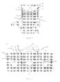
- Figure 1 shows schematically a front view of a part of a disk 2 for a turbine section of a gas turbine engine.
- a row of circumferentially spaced turbine blades is mounted to the disk, the roots 4 of three of the blades being shown in Figure 1 .
- Each root is formed as a fir tree, tapering inwardly in width with increasing inwardly radial distance between circumferentially spaced sides, and with a series of fore-to-aft extending projections 6 and grooves 8 formed by the sides.
- the disk has circumferentially spaced, radially extending posts 10 between which are formed fir tree recesses. The sides of the recesses also form a series of fore-to-aft extending projections 12 and grooves 14.
- the roots 4 slide into the recess in the direction of extension of the projections 6, 12 and grooves 8, 14, with the projections on the sides of the roots fitting into the grooves on the sides of the recesses, and the projections on the sides of the recesses fitting into the grooves on the sides of the roots.
- Spaces 16 are formed between the bases of the roots 4 and the bottoms of the recesses to receive cooling air bled from the compressor. This cooling air enters internal passages (not shown) in the roots and is conveyed radially outwardly to cool the airfoil sections of the blades.
- the projections 6, 14 are truncated so that they do not completely fill the grooves into which they are fitted. This is illustrated in the close-up of two neighbouring projections shown in Figure 1 .
- the portions of the projections in the close-up which are more darkly shaded represent material that is absent due to the truncation of the projections.
- This absence of material provides cooling passages 18a from the truncated projection 6 and cooling passages 18b from the truncated projection 14, both sets of cooling passages extending from the forward to rearward sides of the disk.
- the cooling passages also receive cooling air bled from the compressor, as discussed more fully below.
- the respective angles ⁇ 1 , ⁇ 2 of the surfaces 6a, 14a formed by the truncations can be varied, as can the respective depths t 1 , t 2 of the truncations.
- the angles and depths are such that each pair of neighbouring cooling passages 18a, b are connected to each other via a fore-to-aft-extending opening 20. This opening can help to increase the circulation and hence the effectiveness of the cooling air in the neighbouring cooling passages.
- the truncations also allow oxidation-resistant and/or sulphidation-resistant coating to be applied more easily to surfaces of the fir tree roots 4 and the recesses.
- the truncations reduce the total surface areas of the roots and recesses that are in close contact. That is, in the non-contacting areas the increased clearance between the roots and the recesses facilitates coating formation.
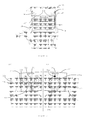
- Figure 2 shows a pattern of cooling air flow on a schematic longitudinal cross-section through the disk 2 of Figure 1 and the root 4 of a blade mounted to the disk
- Figure 3 shows the pattern of cooling air flow on (a) the front view of a part of the disk, and (b) a schematic rear view of a part of the disk.
- directions of cooling air flow are indicated by arrows.
- the blades are retained axially in position by forward 22 and rearward 24 lock plates at respectively the forward and rearward sides of the disk 2.
- Each lock plate which is approximately rectangular in shape, is centred on a respective post 10 and extends circumferentially on both sides of the post to about the midlines of the roots 4 of the neighbouring blades.
- the lock plates are held in position at their radially inward edges by forward 26 and rearward 28 disk rim cover plates, and at their radially outward edges by the blade platforms 30 of the neighbouring blades.
- Each forward lock plate 22 has recesses formed in its face directed towards the disk 2. These recesses can be formed e.g. by trenches in the face of the lock plate or between raised walls on the face of the lock plate. When the lock plate is in position, the face presses against the substantially planar surface formed by the front of the post 10 and the front of the roots 4.
- the recesses thus form channels 32a, 32b for the flow of cooling air.
- respective side channels 32a extend to each pair of neighbouring cooling passages 18a, b from a radially extending central channel 32b. This central channel receives at its inward end a flow of cooling air bled from the compressor.
- the side channels 32a then direct portions of the cooling air to their respective cooling passages.
- a further portion of the cooling air continues up the central channel and exits into a space between the top of the post and the blade platforms 30. It is there deflected on to the top surface of the post by a front deflector plate 34, and subsequently exits the space through apertures in or between the platforms.
- the portions of cooling air directed to the cooling passages 18a, b flow through the passages to cool the surrounding metal of the posts 10 and roots 4. They then exit the passages at the rear of the disk.
- the rear lock plate has recesses in its face directed towards the substantially planar surface formed by the rear of the post 10 and the rear of the roots 4. The face presses against the planar surface, whereby the recesses form side channels 36a and a radially extending central channel 36b.
- the side channels collect the air flow exiting from the cooling passages and direct it to the central channel where it too exits into the space between the top of the post and the blade platforms 30.
- the collected air is deflected on to the top surface of the post by a rear deflector plate 38, and also exits the space through the apertures in or between the platforms.
- the channels 32a, 32b, 36a, 36b from recesses in the forward 22 and rearward 24 lock plates allows the channel configuration to be modified, should that be necessary, simply by changing the plates.
- the relatively expensive disk 2 and blades do not need to be altered.
- the channels allow the cooling air to be partitioned between the cooling passages 18a, b more accurately and directed thereto more efficiently.
- cooling schemes can be implemented in which e.g. some cooling passages receive most of the cooling air flow at the expense of other passages, or cooling air is returned by the rearward lock plate through cooling passages to the front of the disk to provide an interlacing cooling flow in the cooling passages around the roots 4.
- Figure 4 shows a different pattern of cooling air flow on the schematic longitudinal cross-section through the disk 2 of Figure 1 and the root 4 of a blade mounted to the disk
- Figure 5 shows the different pattern of cooling air flow on (a) the front view of a part of the disk, and (b) the rear view of a part of the disk.
- directions of cooling air flow are indicated by arrows.
- the different pattern of cooling air flow allows the cooling air to flow simultaneously front to back and back to front through respective pairs of neighbouring cooling passages 18a, b, rather than solely front to back as in Figure 2 and 3 .
- This different pattern is achieved simply by replacing the forward 22 and rearward 24 lock plates of Figures 2 and 3 , with forward 22' and rearward 24' lock plates having altered arrangements of recesses.
- each forward lock plate has recesses defining a central, radially extending channel 32b' and side channels 32a' extending therefrom to direct portions of the cooling air to respective (first) cooling passages.
- the forward lock plate also has dog-leg-shaped recesses defining side channels 36a' which collect cooling air from other respective (second) cooling passages and send the collected cooling air into the space between the top of the post and the blade platforms 30.
- each rearward lock plate has recesses defining side channels 36a' and a radially extending central channel 36b'.
- the side channels collecting the air flow exiting from the first cooling passages and direct it to the central channel where it too exits into the space between the top of the post and the blade platforms 30.
- the rearward lock plate also has recesses defining a central, radially extending channel 32b' and side channels 32a' extending therefrom to direct portions of the cooling air to the second cooling passages.
- the cooling air flow arrives at the central, radially extending channel 32b' of the rearward lock plate via the space 16 formed between the base of the root 4 and the bottom of the corresponding recess.
Landscapes
- Engineering & Computer Science (AREA)
- Mechanical Engineering (AREA)
- General Engineering & Computer Science (AREA)
- Turbine Rotor Nozzle Sealing (AREA)
Abstract
Description
- The present invention relates to a turbine disk and blade arrangement.
- In gas turbine engines, it is well known to connect turbine blades to turbine disks using "fir tree" connections. In such connections, each blade has a fir tree root which tapers inwardly in width with increasing inwards radial distance, the root being slidably insertable, along a substantially axial direction of the engine, into a respective conforming fir tree recess formed in the disk. The facing sides of the fir tree root and fir tree recess have respective interengaging serrations which take the form of projections and grooves extending in the direction of insertion of the root into the recess. In this way, the blades can be prevented from flying outwardly from the disk during operation of the engine.
- It is also known to provide a space between the radially inward end of the blade root and the bottom of the recess so that cooling air, bled from the compressor, can be fed into the space, and from thence along interior channels in the blade, to cool the blade airfoil.
- Although, such airfoil cooling can be effective, there still remains a problem of cooling the fir tree roots and the posts which extend radially from the disk to define the fir tree recesses therebetween.
- To improve cooling in these regions,
US 2004/0191067 proposes truncating some of the fir tree projections to form cooling air flow paths extending from the front to the rear of the disk, and to supply such flow paths with cooling air bled from the compressor. In particular,US 2004/0191067 proposes positioning a flange which covers the fir tree engaging features but is spaced therefrom so as to allow entry of cooling air via the space into the forward ends of the flow paths. - However, there remains a need to further improve the cooling of the fir tree roots and the posts.
- Accordingly, a first aspect of the present invention provides a turbine disk and blade arrangement for a gas turbine engine in which a plurality of turbine blades are mounted circumferentially around a disk, each blade having a fir tree root which provides on circumferentially spaced sides thereof a series of fore-to-aft-extending projections and grooves, and the disk having a plurality of circumferentially spaced, radially extending posts which define fir tree recesses therebetween, each fir tree recess also providing on circumferentially spaced sides thereof a series of fore-to-aft-extending projections and grooves, each fir tree root being slidable into a respective fir tree recess with the projections and grooves on facing sides of the fir tree root and the fir tree recess interengaging with each other;
wherein: - on each pair of facing sides of the fir tree root and the fir tree recess, one or more of the projections of the fir tree roots and/or the fir tree recesses are truncated to form fore-to-aft-extending cooling passages between facing sides of the fir tree roots and fir tree recesses, and
- the arrangement has first lock plates which cover forward surfaces of the posts and of the fir tree roots and/or cover rearward surfaces of the posts and of the fir tree roots, the first lock plates and the posts defining feed channels therebetween which feed cooling air to the cooling passages, each cooling passage extending to a respective feed channel.
- Thus by means of the feed channels, cooling air can be directed specifically to the cooling passages, rather than generally to a space in front of the fir tree engaging features. This allows the cooling air to be used more efficiently. Also, by appropriate sizing of the feed channels, cooling air can be directed preferentially to certain cooling passages, e.g. cooling passages where the surrounding metal temperature is higher.
- Disk failures usually initiate at the bases of the grooves of the fir tree recess, or at the edge of the contact patch between the projections of the fir tree root and the fir tree recess. By deploying the cooling air more efficiently to these regions, it is possible to increase disk lifetimes.
- The turbine disk and blade arrangement of the first aspect may have any one or, to the extent that they are compatible, any combination of the following optional features.
- Preferably, the arrangement further has second lock plates which cover forward surfaces of the posts and of the fir tree roots and/or cover rearward surfaces of the posts and of the fir tree roots, the second lock plates and the posts defining collection channels therebetween which collect cooling air from the cooling passages, each collection channel extending from a respective cooling passage.
- Like the first lock plates, the second lock plates allow the cooling air to be used more efficiently. For example, the collected cooling air can be guided by the collection channels to further locations requiring cooling, such as the tops of the posts. The collection channels can even redirect the cooling air back to the front of the disk, e.g. through further cooling passages formed by truncated fir tree projections.
- Typically, the first lock plates cover the forward surfaces of the posts and of the fir tree roots. In this case, the second lock plates can cover the rearward surfaces of the posts and of the fir tree roots.
- However, it is possible for lock plates covering the forward surfaces of the posts and of the fir tree roots to define feed channels which feed cooling air to a first portion of the cooling passages and also to define collection channels which collect cooling air from a second portion of the cooling passages, i.e. the lock plates can have a dual function. Likewise, it is possible for lock plates covering the rearward surfaces of the posts and of the fir tree roots to define feed channels which feed cooling air to the second portion of the cooling passages and also to define collection channels which collect cooling air from the first portion of the cooling passages. In this way, cooling air can flow simultaneously front to back and back to front through respective cooling passages.
- Preferably, the faces of the first lock plates, and optionally the faces of the second lock plates, facing the posts have recesses formed therein corresponding to the paths of the channels, said faces of the lock plates contacting the respective surfaces of the posts around the perimeters of the recesses so that the recesses form the channels.
- In this way, it is possible to modify the flow of cooling air by changing the configuration of the recesses provided by the lock plates rather than modifying relatively expensive items such as the disk and blades.
- The recess can be formed e.g. by trenches in the faces of the lock plates or between raised walls on the faces of the lock plates.
- On each pair of facing sides of the fir tree root and the fir tree recess, one or more projections of the fir tree root may be truncated to form respective fore-to-aft-extending first cooling passages between the facing sides, and one or more neighbouring projections of the fir tree recess may be truncated to form respective fore-to-aft-extending second cooling passages between the facing sides, the truncations being shaped so that neighbouring first and second cooling passages are connected to each other along respective fore-to-aft-extending openings.
- Indeed, a further aspect of the present invention provides a turbine disk and blade arrangement for a gas turbine engine in which a plurality of turbine blades are mounted circumferentially around a disk, each blade having a fir tree root which provides on circumferentially spaced sides thereof a series of fore-to-aft-extending projections and grooves, and the disk having a plurality of circumferentially spaced, radially extending posts which define fir tree recesses therebetween, each fir tree recess also providing on circumferentially spaced sides thereof a series of fore-to-aft-extending projections and grooves, each fir tree root being slidable into a respective fir tree recess with the projections and grooves on facing sides of the fir tree root and the fir tree recess interengaging with each other;
wherein: - on each pair of facing sides of the fir tree root and the fir tree recess, one or more projections of the fir tree root are truncated to form respective fore-to-aft-extending first cooling passages between the facing sides, and one or more neighbouring projections of the fir tree recess are truncated to form respective fore-to-aft-extending second cooling passages between the facing sides, the truncations being shaped so that neighbouring first and second cooling passages are connected to each other along respective fore-to-aft-extending openings.
- By connecting neighbouring first and second cooling passages to each other along the openings, further improved cooling of the fir tree roots and posts can be achieved. Also it can be possible to direct cooling air to just one of neighbouring first and second cooling passages (e.g. by an appropriate feed channel) but achieve cooling inside both of the passages.
- Additionally, the truncations can produce significant weight reductions due to the reduction in metal required to form the posts and the fir tree roots.
- The turbine disk and blade arrangement of the first or second aspect may have any one or, to the extent that they are compatible, any combination of the following optional features.
- Preferably, the circumferentially spaced sides of the fir tree roots and/or the fir tree recesses carry an oxidation-resistant and/or sulphidation-resistant coating. For example, the coating can be a platinum or aluminised sulphidation-resistant coating.
- Such coatings can significantly extent the lifetimes of the blades and disk, but can be difficult to apply given the usually close tolerances between the facing sides of the fir tree roots and fir tree recesses. However, particularly when the truncations are sized so that neighbouring first and second cooling passages are connected to each other along respective fore-to-aft-extending openings, larger surface areas of the facing sides may not be in direct contact with each other, allowing the coatings to be applied at least in these regions.
- Embodiments of the invention will now be described by way of example with reference to the accompanying drawings in which:
-
Figure 1 shows schematically a front view of a part of a disk and the roots of three blades mounted to the disk; -
Figure 2 shows a pattern of cooling air flow on a schematic longitudinal cross-section through the disk ofFigure 1 and the root of a blade mounted to the disk; -
Figure 3 shows the pattern of cooling air flow ofFigure 2 on (a) the front view of a part of the disk ofFigure 1 , and (b) a schematic rear view of a part of the disk ofFigure 1 ; -
Figure 4 shows a further pattern of cooling air flow on the schematic longitudinal cross-section through the disk ofFigure 1 and the root of a blade mounted to the disk; and -
Figure 5 shows the pattern of cooling air flow ofFigure 4 on (a) the front view of a part of the disk ofFigure 1 , and (b) the rear view of a part of the disk ofFigure 1 . -
Figure 1 shows schematically a front view of a part of adisk 2 for a turbine section of a gas turbine engine. A row of circumferentially spaced turbine blades is mounted to the disk, theroots 4 of three of the blades being shown inFigure 1 . Each root is formed as a fir tree, tapering inwardly in width with increasing inwardly radial distance between circumferentially spaced sides, and with a series of fore-to-aft extending projections 6 and grooves 8 formed by the sides. The disk has circumferentially spaced, radially extendingposts 10 between which are formed fir tree recesses. The sides of the recesses also form a series of fore-to-aft extending projections 12 andgrooves 14. - To mount the blades to the
disk 2, theroots 4 slide into the recess in the direction of extension of theprojections 6, 12 andgrooves 8, 14, with the projections on the sides of the roots fitting into the grooves on the sides of the recesses, and the projections on the sides of the recesses fitting into the grooves on the sides of the roots. -
Spaces 16 are formed between the bases of theroots 4 and the bottoms of the recesses to receive cooling air bled from the compressor. This cooling air enters internal passages (not shown) in the roots and is conveyed radially outwardly to cool the airfoil sections of the blades. - The
projections 6, 14 are truncated so that they do not completely fill the grooves into which they are fitted. This is illustrated in the close-up of two neighbouring projections shown inFigure 1 . The portions of the projections in the close-up which are more darkly shaded represent material that is absent due to the truncation of the projections. This absence of material providescooling passages 18a from the truncated projection 6 andcooling passages 18b from thetruncated projection 14, both sets of cooling passages extending from the forward to rearward sides of the disk. Like thespaces 16, the cooling passages also receive cooling air bled from the compressor, as discussed more fully below. - The respective angles α1, α2 of the surfaces 6a, 14a formed by the truncations can be varied, as can the respective depths t1, t2 of the truncations. However, preferably, the angles and depths are such that each pair of neighbouring
cooling passages 18a, b are connected to each other via a fore-to-aft-extendingopening 20. This opening can help to increase the circulation and hence the effectiveness of the cooling air in the neighbouring cooling passages. - The truncations also allow oxidation-resistant and/or sulphidation-resistant coating to be applied more easily to surfaces of the
fir tree roots 4 and the recesses. In particular, the truncations reduce the total surface areas of the roots and recesses that are in close contact. That is, in the non-contacting areas the increased clearance between the roots and the recesses facilitates coating formation. -
Figure 2 shows a pattern of cooling air flow on a schematic longitudinal cross-section through thedisk 2 ofFigure 1 and theroot 4 of a blade mounted to the disk, andFigure 3 shows the pattern of cooling air flow on (a) the front view of a part of the disk, and (b) a schematic rear view of a part of the disk. InFigures 2 and 3 directions of cooling air flow are indicated by arrows. - As shown in
Figures 2 and 3 , the blades are retained axially in position by forward 22 and rearward 24 lock plates at respectively the forward and rearward sides of thedisk 2. Each lock plate, which is approximately rectangular in shape, is centred on arespective post 10 and extends circumferentially on both sides of the post to about the midlines of theroots 4 of the neighbouring blades. The lock plates are held in position at their radially inward edges by forward 26 and rearward 28 disk rim cover plates, and at their radially outward edges by theblade platforms 30 of the neighbouring blades. - Each
forward lock plate 22 has recesses formed in its face directed towards thedisk 2. These recesses can be formed e.g. by trenches in the face of the lock plate or between raised walls on the face of the lock plate. When the lock plate is in position, the face presses against the substantially planar surface formed by the front of thepost 10 and the front of theroots 4. The recesses thus formchannels Figure 3(a) ,respective side channels 32a extend to each pair of neighbouringcooling passages 18a, b from a radially extendingcentral channel 32b. This central channel receives at its inward end a flow of cooling air bled from the compressor. Theside channels 32a then direct portions of the cooling air to their respective cooling passages. A further portion of the cooling air continues up the central channel and exits into a space between the top of the post and theblade platforms 30. It is there deflected on to the top surface of the post by afront deflector plate 34, and subsequently exits the space through apertures in or between the platforms. - The portions of cooling air directed to the
cooling passages 18a, b flow through the passages to cool the surrounding metal of theposts 10 androots 4. They then exit the passages at the rear of the disk. The rear lock plate has recesses in its face directed towards the substantially planar surface formed by the rear of thepost 10 and the rear of theroots 4. The face presses against the planar surface, whereby the recesses formside channels 36a and a radially extendingcentral channel 36b. The side channels collect the air flow exiting from the cooling passages and direct it to the central channel where it too exits into the space between the top of the post and theblade platforms 30. The collected air is deflected on to the top surface of the post by arear deflector plate 38, and also exits the space through the apertures in or between the platforms. - Forming the
channels expensive disk 2 and blades do not need to be altered. Further, compared to the arrangement ofUS 2004/0191067 in which cooling air is simply introduced into a space infront of the fir tree roots, the channels allow the cooling air to be partitioned between thecooling passages 18a, b more accurately and directed thereto more efficiently. For example, cooling schemes can be implemented in which e.g. some cooling passages receive most of the cooling air flow at the expense of other passages, or cooling air is returned by the rearward lock plate through cooling passages to the front of the disk to provide an interlacing cooling flow in the cooling passages around theroots 4. -
Figure 4 shows a different pattern of cooling air flow on the schematic longitudinal cross-section through thedisk 2 ofFigure 1 and theroot 4 of a blade mounted to the disk, andFigure 5 shows the different pattern of cooling air flow on (a) the front view of a part of the disk, and (b) the rear view of a part of the disk. InFigures 4 and 5 directions of cooling air flow are indicated by arrows. Corresponding features having the same reference numbers inFigures 4 and 5 and they do inFigure 2 and 3 . - The different pattern of cooling air flow allows the cooling air to flow simultaneously front to back and back to front through respective pairs of neighbouring
cooling passages 18a, b, rather than solely front to back as inFigure 2 and 3 . This different pattern is achieved simply by replacing the forward 22 and rearward 24 lock plates ofFigures 2 and 3 , with forward 22' and rearward 24' lock plates having altered arrangements of recesses. - In particular, each forward lock plate has recesses defining a central, radially extending
channel 32b' andside channels 32a' extending therefrom to direct portions of the cooling air to respective (first) cooling passages. However, the forward lock plate also has dog-leg-shaped recesses definingside channels 36a' which collect cooling air from other respective (second) cooling passages and send the collected cooling air into the space between the top of the post and theblade platforms 30. - Further, each rearward lock plate has recesses defining
side channels 36a' and a radially extendingcentral channel 36b'. The side channels collecting the air flow exiting from the first cooling passages and direct it to the central channel where it too exits into the space between the top of the post and theblade platforms 30. However, the rearward lock plate also has recesses defining a central, radially extendingchannel 32b' andside channels 32a' extending therefrom to direct portions of the cooling air to the second cooling passages. The cooling air flow arrives at the central, radially extendingchannel 32b' of the rearward lock plate via thespace 16 formed between the base of theroot 4 and the bottom of the corresponding recess. - While the invention has been described in conjunction with the exemplary embodiments described above, many equivalent modifications and variations will be apparent to those skilled in the art when given this disclosure. Accordingly, the exemplary embodiments of the invention set forth above are considered to be illustrative and not limiting. Various changes to the described embodiments may be made without departing from the spirit and scope of the invention.
- All references referred to above are hereby incorporated by reference.
Claims (8)
- A turbine disk and blade arrangement for a gas turbine engine in which a plurality of turbine blades are mounted circumferentially around a disk (2), each blade having a fir tree root (4) which provides on circumferentially spaced sides thereof a series of fore-to-aft-extending projections (6) and grooves (8), and the disk having a plurality of circumferentially spaced, radially extending posts (10) which define fir tree recesses therebetween, each fir tree recess also providing on circumferentially spaced sides thereof a series of fore-to-aft-extending projections (12) and grooves (14), each fir tree root being slidable into a respective fir tree recess with the projections and grooves on facing sides of the fir tree root and the fir tree recess interengaging with each other; wherein on each pair of facing sides of the fir tree root and the fir tree recess, one or more of the projections of the fir tree roots and/or the fir tree recesses are truncated to form fore-to-aft-extending cooling passages (18a, 18b) between facing sides of the fir tree roots and fir tree recesses, and the arrangement has lock plates (22; 22', 24') which cover forward surfaces of the posts and of the fir tree roots and/or cover rearward surfaces of the posts and of the fir tree roots, the lock plates and the posts defining feed channels (32a) therebetween which feed cooling air to the cooling passages, each cooling passage extending to a respective feed channel.
- A turbine disk and blade arrangement according to claim 1, wherein the arrangement further has further lock plates (24; 22', 24') which cover forward surfaces of the posts and of the fir tree roots and/or cover rearward surfaces of the posts and of the fir tree roots, the further lock plates and the posts defining collection channels (36a) therebetween which collect cooling air from the cooling passages, each collection channel extending from a respective cooling passage.
- A turbine disk and blade arrangement according to claim 1 or 2, wherein the lock plates defining feed channels cover the forward surfaces of the posts and of the fir tree roots, and the lock plates defining collection channels cover the rearward surfaces of the posts and of the fir tree roots.
- A turbine disk and blade arrangement according to any one of the previous claims, wherein the faces of the lock plates facing the posts have recesses formed therein corresponding to the paths of the channels, said sides of the lock plates contacting the respective surfaces of the posts around the perimeters of the recesses so that the recesses form the channels.
- A turbine disk and blade arrangement according to any one of the previous claims, wherein, on each pair of facing sides of the fir tree root and the fir tree recess, one or more projections of the fir tree root are truncated to form respective fore-to-aft-extending first cooling passages between the facing sides, and one or more neighbouring projections of the fir tree recess are truncated to form respective fore-to-aft-extending second cooling passages between the facing sides, the truncations being shaped so that neighbouring first and second cooling passages are connected to each other along respective fore-to-aft-extending openings (20).
- A turbine disk and blade arrangement for a gas turbine engine in which a plurality of turbine blades are mounted circumferentially around a disk (2), each blade having a fir tree root (4) which provides on circumferentially spaced sides thereof a series of fore-to-aft-extending projections (6) and grooves (8), and the disk having a plurality of circumferentially spaced, radially extending posts (10) which define fir tree recesses therebetween, each fir tree recess also providing on circumferentially spaced sides thereof a series of fore-to-aft-extending projections (12) and grooves (14), each fir tree root being slidable into a respective fir tree recess with the projections and grooves on facing sides of the fir tree root and the fir tree recess interengaging with each other; wherein on each pair of facing sides of the fir tree root and the fir tree recess, one or more projections of the fir tree root are truncated to form respective fore-to-aft-extending first cooling passages (18a) between the facing sides, and one or more neighbouring projections of the fir tree recess are truncated to form respective fore-to-aft-extending second cooling passages (18b) between the facing sides, the truncations being shaped so that neighbouring first and second cooling passages are connected to each other along respective fore-to-aft-extending openings (20).
- A turbine disk and blade arrangement according to any one of the previous claims, wherein the circumferentially spaced sides of the fir tree roots and/or the fir tree recesses carry an oxidation-resistant and/or sulphidation-resistant coating.
- A turbine disk and blade arrangement according to claim 7, wherein the circumferentially spaced sides of the fir tree roots and/or the fir tree recesses carry a platinum or aluminised sulphidation-resistant coating.
Applications Claiming Priority (1)
| Application Number | Priority Date | Filing Date | Title |
|---|---|---|---|
| GBGB1002679.7A GB201002679D0 (en) | 2010-02-17 | 2010-02-17 | Turbine disk and blade arrangement |
Publications (3)
| Publication Number | Publication Date |
|---|---|
| EP2357321A2 true EP2357321A2 (en) | 2011-08-17 |
| EP2357321A3 EP2357321A3 (en) | 2013-08-14 |
| EP2357321B1 EP2357321B1 (en) | 2016-12-28 |
Family
ID=42113942
Family Applications (1)
| Application Number | Title | Priority Date | Filing Date |
|---|---|---|---|
| EP11153490.5A Active EP2357321B1 (en) | 2010-02-17 | 2011-02-07 | Turbine disk and blade arrangement |
Country Status (3)
| Country | Link |
|---|---|
| US (1) | US8696304B2 (en) |
| EP (1) | EP2357321B1 (en) |
| GB (1) | GB201002679D0 (en) |
Cited By (3)
| Publication number | Priority date | Publication date | Assignee | Title |
|---|---|---|---|---|
| EP3034795A1 (en) * | 2014-12-17 | 2016-06-22 | Alstom Technology Ltd | Lock plate with radial grooves |
| GB2538389A (en) * | 2015-05-12 | 2016-11-16 | Rolls Royce Plc | A bladed rotor for a gas turbine engine |
| FR3132540A1 (en) * | 2022-02-10 | 2023-08-11 | Safran Aircraft Engines | Turbine rotor comprising a blade stop ring configured to promote cooling of the blade roots. |
Families Citing this family (10)
| Publication number | Priority date | Publication date | Assignee | Title |
|---|---|---|---|---|
| US9109457B2 (en) * | 2010-09-03 | 2015-08-18 | Siemens Energy, Inc. | Axial locking seals for aft removable turbine blade |
| RU2566697C2 (en) | 2011-04-13 | 2015-10-27 | Роллс-Ройс Корпорейшн | Interfacial diffusion barrier layer including iridium on metallic substrate |
| US10822952B2 (en) | 2013-10-03 | 2020-11-03 | Raytheon Technologies Corporation | Feature to provide cooling flow to disk |
| US9938835B2 (en) * | 2013-10-31 | 2018-04-10 | General Electric Company | Method and systems for providing cooling for a turbine assembly |
| EP2918705B1 (en) * | 2014-03-12 | 2017-05-03 | Rolls-Royce Corporation | Coating including diffusion barrier layer including iridium and oxide layer and method of coating |
| US10689988B2 (en) * | 2014-06-12 | 2020-06-23 | Raytheon Technologies Corporation | Disk lug impingement for gas turbine engine airfoil |
| GB201417039D0 (en) | 2014-09-26 | 2014-11-12 | Rolls Royce Plc | A bladed rotor arrangement and a lock plate for a bladed rotor arrangement |
| EP3043024A1 (en) * | 2015-01-09 | 2016-07-13 | Siemens Aktiengesellschaft | Blade platform cooling and corresponding gas turbine |
| FR3049307B1 (en) * | 2016-03-25 | 2019-11-01 | Safran Aircraft Engines | ROTARY ASSEMBLY FOR TURBOMACHINE |
| KR20230122913A (en) * | 2022-02-15 | 2023-08-22 | 두산에너빌리티 주식회사 | Assembling structure of compressor blade seal and Gas turbine comprising the same |
Citations (1)
| Publication number | Priority date | Publication date | Assignee | Title |
|---|---|---|---|---|
| US20040191067A1 (en) | 2003-03-26 | 2004-09-30 | Rolls-Royce Plc | Method of and structure for enabling cooling of the engaging firtree features of a turbine disk and associated blades |
Family Cites Families (9)
| Publication number | Priority date | Publication date | Assignee | Title |
|---|---|---|---|---|
| BE486024A (en) | 1947-11-28 | |||
| DE1076446B (en) * | 1957-10-25 | 1960-02-25 | Siemens Ag | Device for blade cooling in gas turbines |
| US3501249A (en) | 1968-06-24 | 1970-03-17 | Westinghouse Electric Corp | Side plates for turbine blades |
| GB1605282A (en) * | 1973-10-27 | 1987-12-23 | Rolls Royce 1971 Ltd | Bladed rotor for gas turbine engine |
| US4648799A (en) * | 1981-09-22 | 1987-03-10 | Westinghouse Electric Corp. | Cooled combustion turbine blade with retrofit blade seal |
| CA1198986A (en) | 1983-12-22 | 1986-01-07 | United Technologies Corporation | Rotor with double pass blade root cooling |
| US5795659A (en) * | 1992-09-05 | 1998-08-18 | International Inc. | Aluminide-silicide coatings coated products |
| DE19950109A1 (en) * | 1999-10-18 | 2001-04-19 | Asea Brown Boveri | Rotor for a gas turbine |
| GB2409240B (en) * | 2003-12-18 | 2007-04-11 | Rolls Royce Plc | A gas turbine rotor |
-
2010
- 2010-02-17 GB GBGB1002679.7A patent/GB201002679D0/en not_active Ceased
-
2011
- 2011-02-07 US US13/022,034 patent/US8696304B2/en active Active
- 2011-02-07 EP EP11153490.5A patent/EP2357321B1/en active Active
Patent Citations (1)
| Publication number | Priority date | Publication date | Assignee | Title |
|---|---|---|---|---|
| US20040191067A1 (en) | 2003-03-26 | 2004-09-30 | Rolls-Royce Plc | Method of and structure for enabling cooling of the engaging firtree features of a turbine disk and associated blades |
Cited By (7)
| Publication number | Priority date | Publication date | Assignee | Title |
|---|---|---|---|---|
| EP3034795A1 (en) * | 2014-12-17 | 2016-06-22 | Alstom Technology Ltd | Lock plate with radial grooves |
| US10132172B2 (en) | 2014-12-17 | 2018-11-20 | Ansaldo Energia Switzerland AG | Arrangement of a rotor and at least a blade |
| GB2538389A (en) * | 2015-05-12 | 2016-11-16 | Rolls Royce Plc | A bladed rotor for a gas turbine engine |
| US10280766B2 (en) | 2015-05-12 | 2019-05-07 | Rolls-Royce Plc | Bladed rotor for a gas turbine engine |
| GB2538389B (en) * | 2015-05-12 | 2020-05-06 | Rolls Royce Plc | A bladed rotor for a gas turbine engine |
| FR3132540A1 (en) * | 2022-02-10 | 2023-08-11 | Safran Aircraft Engines | Turbine rotor comprising a blade stop ring configured to promote cooling of the blade roots. |
| WO2023152440A1 (en) | 2022-02-10 | 2023-08-17 | Safran Aircraft Engines | Turbine rotor comprising a blade stop ring configured to aid the cooling of the blade roots |
Also Published As
| Publication number | Publication date |
|---|---|
| GB201002679D0 (en) | 2010-04-07 |
| EP2357321A3 (en) | 2013-08-14 |
| EP2357321B1 (en) | 2016-12-28 |
| US20110200448A1 (en) | 2011-08-18 |
| US8696304B2 (en) | 2014-04-15 |
Similar Documents
| Publication | Publication Date | Title |
|---|---|---|
| US8696304B2 (en) | Turbine disk and blade arrangement | |
| US8814518B2 (en) | Apparatus and methods for cooling platform regions of turbine rotor blades | |
| JP5410011B2 (en) | Double feed serpentine cooling blade | |
| EP2540971B1 (en) | Method for creating a platform cooling passage in a turbine rotor blade and corresponding turbine rotor blade | |
| EP1162346B1 (en) | Cooled turbine component, shroud segment, and corresponding assemblies | |
| JP6030826B2 (en) | Apparatus and method for cooling the platform area of a turbine rotor blade | |
| US5387085A (en) | Turbine blade composite cooling circuit | |
| EP1621731B1 (en) | Common tip chamber blade | |
| EP2204538B1 (en) | Turbine blade cooling circuits | |
| US9011077B2 (en) | Cooled airfoil in a turbine engine | |
| US20120082550A1 (en) | Apparatus and methods for cooling platform regions of turbine rotor blades | |
| US20060263204A1 (en) | Sealing arrangement, in particular for the blade segments of gas turbines | |
| EP2610435B1 (en) | Turbine Rotor Blade Platform Cooling | |
| EP1473439B1 (en) | Cooled castellated turbine airfoil | |
| CN1707069B (en) | Method and apparatus for cooling gas turbine rotor blades | |
| US9238970B2 (en) | Blade outer air seal assembly leading edge core configuration | |
| US20120082564A1 (en) | Apparatus and methods for cooling platform regions of turbine rotor blades | |
| DE102013109146A1 (en) | Cooling arrangement for the platform region of a turbine blade | |
| EP2738350B1 (en) | Turbine blade airfoils including showerhead film cooling systems, and methods for forming an improved showerhead film cooled airfoil of a turbine blade | |
| DE102009059225A1 (en) | Turbine rotor blade tips obstructing a cross flow | |
| US10323520B2 (en) | Platform cooling arrangement in a turbine rotor blade | |
| US20150184537A1 (en) | Interior cooling circuits in turbine blades | |
| CN104285040A (en) | Turbine rotor blade and axial rotor blade section for a gas turbine | |
| CN103089324B (en) | Turbomachine rotor disc and cooling means thereof | |
| EP2796666B1 (en) | Turbine blade airfoils including a film cooling system, and method for forming an improved film cooled airfoil of a turbine blade |
Legal Events
| Date | Code | Title | Description |
|---|---|---|---|
| PUAI | Public reference made under article 153(3) epc to a published international application that has entered the european phase |
Free format text: ORIGINAL CODE: 0009012 |
|
| AK | Designated contracting states |
Kind code of ref document: A2 Designated state(s): AL AT BE BG CH CY CZ DE DK EE ES FI FR GB GR HR HU IE IS IT LI LT LU LV MC MK MT NL NO PL PT RO RS SE SI SK SM TR |
|
| AX | Request for extension of the european patent |
Extension state: BA ME |
|
| PUAL | Search report despatched |
Free format text: ORIGINAL CODE: 0009013 |
|
| AK | Designated contracting states |
Kind code of ref document: A3 Designated state(s): AL AT BE BG CH CY CZ DE DK EE ES FI FR GB GR HR HU IE IS IT LI LT LU LV MC MK MT NL NO PL PT RO RS SE SI SK SM TR |
|
| AX | Request for extension of the european patent |
Extension state: BA ME |
|
| RIC1 | Information provided on ipc code assigned before grant |
Ipc: F01D 5/30 20060101AFI20130708BHEP |
|
| 17P | Request for examination filed |
Effective date: 20140214 |
|
| RBV | Designated contracting states (corrected) |
Designated state(s): AL AT BE BG CH CY CZ DE DK EE ES FI FR GB GR HR HU IE IS IT LI LT LU LV MC MK MT NL NO PL PT RO RS SE SI SK SM TR |
|
| RAP1 | Party data changed (applicant data changed or rights of an application transferred) |
Owner name: ROLLS-ROYCE PLC |
|
| REG | Reference to a national code |
Ref country code: DE Ref legal event code: R079 Ref document number: 602011033763 Country of ref document: DE Free format text: PREVIOUS MAIN CLASS: F01D0005300000 Ipc: F01D0005080000 |
|
| GRAP | Despatch of communication of intention to grant a patent |
Free format text: ORIGINAL CODE: EPIDOSNIGR1 |
|
| RIC1 | Information provided on ipc code assigned before grant |
Ipc: F01D 5/08 20060101AFI20160906BHEP |
|
| INTG | Intention to grant announced |
Effective date: 20160922 |
|
| GRAS | Grant fee paid |
Free format text: ORIGINAL CODE: EPIDOSNIGR3 |
|
| STAA | Information on the status of an ep patent application or granted ep patent |
Free format text: STATUS: GRANT OF PATENT IS INTENDED |
|
| GRAA | (expected) grant |
Free format text: ORIGINAL CODE: 0009210 |
|
| STAA | Information on the status of an ep patent application or granted ep patent |
Free format text: STATUS: THE PATENT HAS BEEN GRANTED |
|
| AK | Designated contracting states |
Kind code of ref document: B1 Designated state(s): AL AT BE BG CH CY CZ DE DK EE ES FI FR GB GR HR HU IE IS IT LI LT LU LV MC MK MT NL NO PL PT RO RS SE SI SK SM TR |
|
| REG | Reference to a national code |
Ref country code: GB Ref legal event code: FG4D |
|
| REG | Reference to a national code |
Ref country code: CH Ref legal event code: EP |
|
| REG | Reference to a national code |
Ref country code: AT Ref legal event code: REF Ref document number: 857481 Country of ref document: AT Kind code of ref document: T Effective date: 20170115 |
|
| REG | Reference to a national code |
Ref country code: IE Ref legal event code: FG4D |
|
| REG | Reference to a national code |
Ref country code: DE Ref legal event code: R096 Ref document number: 602011033763 Country of ref document: DE |
|
| REG | Reference to a national code |
Ref country code: FR Ref legal event code: PLFP Year of fee payment: 7 |
|
| PG25 | Lapsed in a contracting state [announced via postgrant information from national office to epo] |
Ref country code: LV Free format text: LAPSE BECAUSE OF FAILURE TO SUBMIT A TRANSLATION OF THE DESCRIPTION OR TO PAY THE FEE WITHIN THE PRESCRIBED TIME-LIMIT Effective date: 20161228 |
|
| REG | Reference to a national code |
Ref country code: LT Ref legal event code: MG4D |
|
| PG25 | Lapsed in a contracting state [announced via postgrant information from national office to epo] |
Ref country code: SE Free format text: LAPSE BECAUSE OF FAILURE TO SUBMIT A TRANSLATION OF THE DESCRIPTION OR TO PAY THE FEE WITHIN THE PRESCRIBED TIME-LIMIT Effective date: 20161228 Ref country code: LT Free format text: LAPSE BECAUSE OF FAILURE TO SUBMIT A TRANSLATION OF THE DESCRIPTION OR TO PAY THE FEE WITHIN THE PRESCRIBED TIME-LIMIT Effective date: 20161228 Ref country code: GR Free format text: LAPSE BECAUSE OF FAILURE TO SUBMIT A TRANSLATION OF THE DESCRIPTION OR TO PAY THE FEE WITHIN THE PRESCRIBED TIME-LIMIT Effective date: 20170329 Ref country code: NO Free format text: LAPSE BECAUSE OF FAILURE TO SUBMIT A TRANSLATION OF THE DESCRIPTION OR TO PAY THE FEE WITHIN THE PRESCRIBED TIME-LIMIT Effective date: 20170328 |
|
| PGFP | Annual fee paid to national office [announced via postgrant information from national office to epo] |
Ref country code: DE Payment date: 20170227 Year of fee payment: 7 |
|
| REG | Reference to a national code |
Ref country code: NL Ref legal event code: MP Effective date: 20161228 |
|
| REG | Reference to a national code |
Ref country code: AT Ref legal event code: MK05 Ref document number: 857481 Country of ref document: AT Kind code of ref document: T Effective date: 20161228 |
|
| PG25 | Lapsed in a contracting state [announced via postgrant information from national office to epo] |
Ref country code: RS Free format text: LAPSE BECAUSE OF FAILURE TO SUBMIT A TRANSLATION OF THE DESCRIPTION OR TO PAY THE FEE WITHIN THE PRESCRIBED TIME-LIMIT Effective date: 20161228 Ref country code: FI Free format text: LAPSE BECAUSE OF FAILURE TO SUBMIT A TRANSLATION OF THE DESCRIPTION OR TO PAY THE FEE WITHIN THE PRESCRIBED TIME-LIMIT Effective date: 20161228 Ref country code: HR Free format text: LAPSE BECAUSE OF FAILURE TO SUBMIT A TRANSLATION OF THE DESCRIPTION OR TO PAY THE FEE WITHIN THE PRESCRIBED TIME-LIMIT Effective date: 20161228 Ref country code: BE Free format text: LAPSE BECAUSE OF NON-PAYMENT OF DUE FEES Effective date: 20170228 |
|
| PG25 | Lapsed in a contracting state [announced via postgrant information from national office to epo] |
Ref country code: NL Free format text: LAPSE BECAUSE OF FAILURE TO SUBMIT A TRANSLATION OF THE DESCRIPTION OR TO PAY THE FEE WITHIN THE PRESCRIBED TIME-LIMIT Effective date: 20161228 |
|
| PG25 | Lapsed in a contracting state [announced via postgrant information from national office to epo] |
Ref country code: RO Free format text: LAPSE BECAUSE OF FAILURE TO SUBMIT A TRANSLATION OF THE DESCRIPTION OR TO PAY THE FEE WITHIN THE PRESCRIBED TIME-LIMIT Effective date: 20161228 Ref country code: CZ Free format text: LAPSE BECAUSE OF FAILURE TO SUBMIT A TRANSLATION OF THE DESCRIPTION OR TO PAY THE FEE WITHIN THE PRESCRIBED TIME-LIMIT Effective date: 20161228 Ref country code: IS Free format text: LAPSE BECAUSE OF FAILURE TO SUBMIT A TRANSLATION OF THE DESCRIPTION OR TO PAY THE FEE WITHIN THE PRESCRIBED TIME-LIMIT Effective date: 20170428 Ref country code: SK Free format text: LAPSE BECAUSE OF FAILURE TO SUBMIT A TRANSLATION OF THE DESCRIPTION OR TO PAY THE FEE WITHIN THE PRESCRIBED TIME-LIMIT Effective date: 20161228 Ref country code: EE Free format text: LAPSE BECAUSE OF FAILURE TO SUBMIT A TRANSLATION OF THE DESCRIPTION OR TO PAY THE FEE WITHIN THE PRESCRIBED TIME-LIMIT Effective date: 20161228 |
|
| PG25 | Lapsed in a contracting state [announced via postgrant information from national office to epo] |
Ref country code: PL Free format text: LAPSE BECAUSE OF FAILURE TO SUBMIT A TRANSLATION OF THE DESCRIPTION OR TO PAY THE FEE WITHIN THE PRESCRIBED TIME-LIMIT Effective date: 20161228 Ref country code: AT Free format text: LAPSE BECAUSE OF FAILURE TO SUBMIT A TRANSLATION OF THE DESCRIPTION OR TO PAY THE FEE WITHIN THE PRESCRIBED TIME-LIMIT Effective date: 20161228 Ref country code: BE Free format text: LAPSE BECAUSE OF FAILURE TO SUBMIT A TRANSLATION OF THE DESCRIPTION OR TO PAY THE FEE WITHIN THE PRESCRIBED TIME-LIMIT Effective date: 20161228 Ref country code: SM Free format text: LAPSE BECAUSE OF FAILURE TO SUBMIT A TRANSLATION OF THE DESCRIPTION OR TO PAY THE FEE WITHIN THE PRESCRIBED TIME-LIMIT Effective date: 20161228 Ref country code: BG Free format text: LAPSE BECAUSE OF FAILURE TO SUBMIT A TRANSLATION OF THE DESCRIPTION OR TO PAY THE FEE WITHIN THE PRESCRIBED TIME-LIMIT Effective date: 20170328 Ref country code: PT Free format text: LAPSE BECAUSE OF FAILURE TO SUBMIT A TRANSLATION OF THE DESCRIPTION OR TO PAY THE FEE WITHIN THE PRESCRIBED TIME-LIMIT Effective date: 20170428 Ref country code: IT Free format text: LAPSE BECAUSE OF FAILURE TO SUBMIT A TRANSLATION OF THE DESCRIPTION OR TO PAY THE FEE WITHIN THE PRESCRIBED TIME-LIMIT Effective date: 20161228 Ref country code: ES Free format text: LAPSE BECAUSE OF FAILURE TO SUBMIT A TRANSLATION OF THE DESCRIPTION OR TO PAY THE FEE WITHIN THE PRESCRIBED TIME-LIMIT Effective date: 20161228 |
|
| PG25 | Lapsed in a contracting state [announced via postgrant information from national office to epo] |
Ref country code: MC Free format text: LAPSE BECAUSE OF FAILURE TO SUBMIT A TRANSLATION OF THE DESCRIPTION OR TO PAY THE FEE WITHIN THE PRESCRIBED TIME-LIMIT Effective date: 20161228 |
|
| REG | Reference to a national code |
Ref country code: CH Ref legal event code: PL Ref country code: DE Ref legal event code: R097 Ref document number: 602011033763 Country of ref document: DE |
|
| PG25 | Lapsed in a contracting state [announced via postgrant information from national office to epo] |
Ref country code: CH Free format text: LAPSE BECAUSE OF NON-PAYMENT OF DUE FEES Effective date: 20170228 Ref country code: LI Free format text: LAPSE BECAUSE OF NON-PAYMENT OF DUE FEES Effective date: 20170228 |
|
| PLBE | No opposition filed within time limit |
Free format text: ORIGINAL CODE: 0009261 |
|
| STAA | Information on the status of an ep patent application or granted ep patent |
Free format text: STATUS: NO OPPOSITION FILED WITHIN TIME LIMIT |
|
| REG | Reference to a national code |
Ref country code: IE Ref legal event code: MM4A |
|
| PG25 | Lapsed in a contracting state [announced via postgrant information from national office to epo] |
Ref country code: DK Free format text: LAPSE BECAUSE OF FAILURE TO SUBMIT A TRANSLATION OF THE DESCRIPTION OR TO PAY THE FEE WITHIN THE PRESCRIBED TIME-LIMIT Effective date: 20161228 |
|
| 26N | No opposition filed |
Effective date: 20170929 |
|
| PG25 | Lapsed in a contracting state [announced via postgrant information from national office to epo] |
Ref country code: LU Free format text: LAPSE BECAUSE OF NON-PAYMENT OF DUE FEES Effective date: 20170207 |
|
| REG | Reference to a national code |
Ref country code: FR Ref legal event code: PLFP Year of fee payment: 8 |
|
| PG25 | Lapsed in a contracting state [announced via postgrant information from national office to epo] |
Ref country code: SI Free format text: LAPSE BECAUSE OF FAILURE TO SUBMIT A TRANSLATION OF THE DESCRIPTION OR TO PAY THE FEE WITHIN THE PRESCRIBED TIME-LIMIT Effective date: 20161228 Ref country code: IE Free format text: LAPSE BECAUSE OF NON-PAYMENT OF DUE FEES Effective date: 20170207 |
|
| REG | Reference to a national code |
Ref country code: DE Ref legal event code: R119 Ref document number: 602011033763 Country of ref document: DE |
|
| PG25 | Lapsed in a contracting state [announced via postgrant information from national office to epo] |
Ref country code: MT Free format text: LAPSE BECAUSE OF NON-PAYMENT OF DUE FEES Effective date: 20170207 |
|
| PG25 | Lapsed in a contracting state [announced via postgrant information from national office to epo] |
Ref country code: DE Free format text: LAPSE BECAUSE OF NON-PAYMENT OF DUE FEES Effective date: 20180901 |
|
| PG25 | Lapsed in a contracting state [announced via postgrant information from national office to epo] |
Ref country code: HU Free format text: LAPSE BECAUSE OF FAILURE TO SUBMIT A TRANSLATION OF THE DESCRIPTION OR TO PAY THE FEE WITHIN THE PRESCRIBED TIME-LIMIT; INVALID AB INITIO Effective date: 20110207 |
|
| PG25 | Lapsed in a contracting state [announced via postgrant information from national office to epo] |
Ref country code: CY Free format text: LAPSE BECAUSE OF NON-PAYMENT OF DUE FEES Effective date: 20161228 |
|
| PG25 | Lapsed in a contracting state [announced via postgrant information from national office to epo] |
Ref country code: MK Free format text: LAPSE BECAUSE OF FAILURE TO SUBMIT A TRANSLATION OF THE DESCRIPTION OR TO PAY THE FEE WITHIN THE PRESCRIBED TIME-LIMIT Effective date: 20161228 |
|
| PG25 | Lapsed in a contracting state [announced via postgrant information from national office to epo] |
Ref country code: TR Free format text: LAPSE BECAUSE OF FAILURE TO SUBMIT A TRANSLATION OF THE DESCRIPTION OR TO PAY THE FEE WITHIN THE PRESCRIBED TIME-LIMIT Effective date: 20161228 |
|
| PG25 | Lapsed in a contracting state [announced via postgrant information from national office to epo] |
Ref country code: AL Free format text: LAPSE BECAUSE OF FAILURE TO SUBMIT A TRANSLATION OF THE DESCRIPTION OR TO PAY THE FEE WITHIN THE PRESCRIBED TIME-LIMIT Effective date: 20161228 |
|
| PGFP | Annual fee paid to national office [announced via postgrant information from national office to epo] |
Ref country code: FR Payment date: 20230223 Year of fee payment: 13 |
|
| PGFP | Annual fee paid to national office [announced via postgrant information from national office to epo] |
Ref country code: GB Payment date: 20230214 Year of fee payment: 13 |
|
| P01 | Opt-out of the competence of the unified patent court (upc) registered |
Effective date: 20230528 |