EP2357271A1 - Method for controlling electrical actuators of a shedding device - Google Patents
Method for controlling electrical actuators of a shedding device Download PDFInfo
- Publication number
- EP2357271A1 EP2357271A1 EP11154283A EP11154283A EP2357271A1 EP 2357271 A1 EP2357271 A1 EP 2357271A1 EP 11154283 A EP11154283 A EP 11154283A EP 11154283 A EP11154283 A EP 11154283A EP 2357271 A1 EP2357271 A1 EP 2357271A1
- Authority
- EP
- European Patent Office
- Prior art keywords
- pick
- acceleration
- movement
- smooth
- determined
- Prior art date
- Legal status (The legal status is an assumption and is not a legal conclusion. Google has not performed a legal analysis and makes no representation as to the accuracy of the status listed.)
- Granted
Links
- 238000000034 method Methods 0.000 title claims abstract description 21
- 230000033001 locomotion Effects 0.000 claims abstract description 109
- 230000001133 acceleration Effects 0.000 claims abstract description 84
- 230000006870 function Effects 0.000 claims description 66
- 230000007480 spreading Effects 0.000 claims description 18
- 238000003892 spreading Methods 0.000 claims description 18
- 238000006073 displacement reaction Methods 0.000 claims description 12
- 230000015654 memory Effects 0.000 claims description 8
- 238000009941 weaving Methods 0.000 claims description 8
- 238000012360 testing method Methods 0.000 claims description 3
- GNFTZDOKVXKIBK-UHFFFAOYSA-N 3-(2-methoxyethoxy)benzohydrazide Chemical compound COCCOC1=CC=CC(C(=O)NN)=C1 GNFTZDOKVXKIBK-UHFFFAOYSA-N 0.000 claims description 2
- YTAHJIFKAKIKAV-XNMGPUDCSA-N [(1R)-3-morpholin-4-yl-1-phenylpropyl] N-[(3S)-2-oxo-5-phenyl-1,3-dihydro-1,4-benzodiazepin-3-yl]carbamate Chemical compound O=C1[C@H](N=C(C2=C(N1)C=CC=C2)C1=CC=CC=C1)NC(O[C@H](CCN1CCOCC1)C1=CC=CC=C1)=O YTAHJIFKAKIKAV-XNMGPUDCSA-N 0.000 claims description 2
- 238000004364 calculation method Methods 0.000 description 10
- 239000013598 vector Substances 0.000 description 10
- 230000007704 transition Effects 0.000 description 4
- 238000013459 approach Methods 0.000 description 3
- 230000005540 biological transmission Effects 0.000 description 3
- 230000007423 decrease Effects 0.000 description 3
- 230000004048 modification Effects 0.000 description 3
- 238000012986 modification Methods 0.000 description 3
- 230000008859 change Effects 0.000 description 2
- 238000000354 decomposition reaction Methods 0.000 description 2
- 230000008569 process Effects 0.000 description 2
- 241000953555 Theama Species 0.000 description 1
- 230000015572 biosynthetic process Effects 0.000 description 1
- 230000003247 decreasing effect Effects 0.000 description 1
- 238000001514 detection method Methods 0.000 description 1
- 239000004744 fabric Substances 0.000 description 1
- 230000001965 increasing effect Effects 0.000 description 1
- 230000013011 mating Effects 0.000 description 1
- 238000005259 measurement Methods 0.000 description 1
- 230000009347 mechanical transmission Effects 0.000 description 1
- 230000000737 periodic effect Effects 0.000 description 1
- 230000010349 pulsation Effects 0.000 description 1
- 238000010223 real-time analysis Methods 0.000 description 1
- 230000002829 reductive effect Effects 0.000 description 1
- 230000000717 retained effect Effects 0.000 description 1
Images


Classifications
-
- D—TEXTILES; PAPER
- D03—WEAVING
- D03C—SHEDDING MECHANISMS; PATTERN CARDS OR CHAINS; PUNCHING OF CARDS; DESIGNING PATTERNS
- D03C13/00—Shedding mechanisms not otherwise provided for
-
- D—TEXTILES; PAPER
- D03—WEAVING
- D03C—SHEDDING MECHANISMS; PATTERN CARDS OR CHAINS; PUNCHING OF CARDS; DESIGNING PATTERNS
- D03C13/00—Shedding mechanisms not otherwise provided for
- D03C13/02—Shedding mechanisms not otherwise provided for with independent drive motors
- D03C13/025—Shedding mechanisms not otherwise provided for with independent drive motors with independent frame drives
-
- D—TEXTILES; PAPER
- D03—WEAVING
- D03C—SHEDDING MECHANISMS; PATTERN CARDS OR CHAINS; PUNCHING OF CARDS; DESIGNING PATTERNS
- D03C3/00—Jacquards
- D03C3/20—Electrically-operated jacquards
- D03C3/205—Independently actuated lifting cords
Definitions
- the invention relates to a method for controlling the electric actuators of a shedding device on a loom.
- the rails can be mounted on frames, in which case the actuator can be of the type described in EP-A-1,489,208 .
- the rails can also be connected each to an arch which winds on a pulley secured to the rotor of a rotary actuator as known from EP-A-0 926 279 .
- the invention intends to remedy more particularly by proposing a new control method that makes it possible to generate a set of setpoint data, for each pick and each actuator or group of actuators, in an optimized manner. .
- the invention taking into account the accelerations at the connection between the given pick, the previous pick and the next pick, makes it possible to determine a motion law compatible with a direct connection with the laws of movement provided for the previous pick and the next pick. Since the parameterized approximation function and the calculation operations are performed on the basis of the remarkable points corresponding to the crowd parameters, these computations can take place dynamically and take account of changes made during weaving to the parameters of the parameters. crowd.
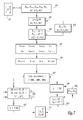
- the loom 2 shown schematically and partially to the figure 1 is equipped with stringer frames, only one of which is visible in this figure, with the reference 4.
- Each stringer frame is set in motion by an electric actuator 6 of the type electric motor, without brush ("brushless").
- Each actuator 6 is connected to a smooth frame 4 by means of a mechanical transmission comprising unrepresented gears and connecting rods including an instrumented pulling rod 8 equipped with a stress measuring cell 10.
- Each cell 10 is connected by a wire link 12 to a measurement conditioner 14.
- Each actuator 6 is controlled by an associated amplifier 16 which manages its current supply, as a function of the position of the rotor, not shown, of this actuator 6 measured by an encoder 18 and as a function of a position command which comes to it in the form of an electronic signal S 1 from a dobby controller 20 which is common for all the actuators 6.
- the dobby controller 20 is connected to the controller 22 of the loom 2 by means of a wire link 24 which allows the exchange of information relating to the operating mode of the loom 2 and the shedding device comprising, inter alia, the actuators 6 and the frames 4.
- the dobby controller 20 comprises a computer 26 which is capable of transmitting the signals S 1 and which is connected by the link 24 to the trade controller 22.
- the computer 26 is also connected to a sensor 28 which provides it with the position of the trade 2 in his cycle.
- the sensor 28 is, for example, a resolver coupled to the main shaft of the loom 2.
- the dobby controller 20 is equipped with a memory 30 in which are stored, in the form of a set of data D 1 , the crowd parameters to be used, these parameters including in particular the armor, the magnitudes of displacement of the frames, the profiles to be followed and the possible time offsets with respect to a median position.
- the controller 20 also comprises a user interface 32 which includes display means 32 1 and input means 32 2 making it possible to modify, among other things, the crowd parameters stored in the memory 30.
- the elements 30 and 32 are connected to the computer 26 by wired links 34 and 36.
- N-order picking is considered within an armor, which can include a large number of picks. This number of picks is called the armor ratio.
- the duit preceding this given cute of order N is the duity of order N-1 and the duity preceding the given duity N of two moves is the duity of order N-2.
- the pick following the given pick of order N is the pick of order N + 1, while the next pick of two moves the given pick of order N is the pick of order N + 2.
- the position setpoint for the control of an actuator 6 is transmitted in the form of a vector V N of thirty-three points which defines a succession, of thirty-two regular intervals, of angular positions of the rotor of this actuator on a business cycle.
- a vector V N is transmitted to each amplifier 16 as part of the signal S 1 transmitted by the computer 26 to this amplifier.
- Each amplifier 16 is capable of interpolating the intermediate positions of the rotor of the actuator that it supplies, between two positions given by the vector V N transmitted to it by the computer 26.
- a business cycle usually corresponds to a 360 ° rotation of the main tree of trade 2.
- the vector V N transmitted to each amplifier 16 for a pick N thus comprises a set of setpoint data which it is important to determine in the best way to obtain a harmonious weave, with optimized accelerations.
- the determination by calculation of each vector or set of reference data V N is carried out by the computer 26.
- the N pick extends over an angular range of about 360 ° of rotation of the business tree.
- ⁇ 1 the position of the business tree at the beginning of the pick N and ⁇ 2 its position at the end of the pick.
- the value of ⁇ 1 is equal to the value of ⁇ 2 , approximately 360 °.
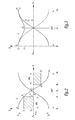
- the figure 2 represents the height y of a part of a rail, which defines the position of a warp passing through this rail, as a function of the working angle ⁇ . In the example shown in solid line at the figure 2 this height varies during the N duit to the extent that the rail passes from an initial position, in which its eyelet is located above a median plane P M of the crowd, to an end position located in below this plan.
- P 1 a point representative of the position of the smooth 1 at the beginning of the N pick, this point being defined by the abscissa ⁇ 1 and by an ordinate y 1 which is strictly positive.
- P 2 a point representative of the position of the smooth at the end of the N pick, this point being defined by the abscissa ⁇ 2 and a strictly negative ordinate y 2 .
- P 3 an intermediate point corresponding to the position of the smooth for a value of the angle ⁇ 3 corresponding to the mid-race on the N duit, that is to say equal to the half sum of the values of ⁇ 1 and ⁇ 2 .
- the intermediate position P 3 corresponds to the position of the bar at 180 °, this position normally corresponding to the swinging stroke of the loom.
- ⁇ i the vertical offset of the point P 3 relative to the plane P M , that is to say the absolute value of the abscissa y 3 of this point which, in the example, is strictly positive.
- P 4 a representative point of the necessary opening of the shed for the passage of a weft yarn in the crowd on an angular stroke starting from the initial angular position ⁇ 1 .
- P 5 a representative point of the necessary opening of the shed for the passage of a weft yarn on an angular stroke leading to the final angular position ⁇ 2 .
- the points P 4 and P 5 are defined by their abscissas ⁇ 4 and ⁇ 5 and their ordinates y 4 and y 5 which are respectively strictly positive and strictly negative.
- the value of y 4 lies between the value of ⁇ 1 and the value of y 1 .
- the curve C along which a rail moves during a pick N can be characterized by the points P 1 to P 5 which are remarkable points corresponding to specific positions of the rail, respectively at the beginning, at the end, at the middle of its displacement as well as in two positions resulting from the desired opening profile for the passage of a weft thread.
- the respective abscissae and ordinates of the remarkable points P 1 to P 5 come from the data of the set of data D 1 stored in the memory 30.
- the computer 26 accesses, in a first step 101 of the process represented in FIG. figure 7 , at the memory 30 to collect the information relating to the points P 1 to P 5 for the pick N as well as for the two previous picks N-1 and N-2 and for the two picks N + 1 and N + 2.
- the computer thus acquires in the memory 30 information relating to the points P 1k , P 2k , P 3k , P 4k and P 5k for the k equal to N-2, N-1, N, N + 1 and N + 2.
- the calculator 26 recovers from the data set D 1 certain crowd parameters such as the amplitude Amp crowd, the desired vertical offset ⁇ 1 at the intermediate point P 3 and the desired opening for the passage of the son of frame.
- the calculator 26 can calculate the ordinates y 1 , y 2 and y 3 and the abscissae and ordinates ⁇ 4 , ⁇ 5 , y 4 , y 5 of the points P 4 and P 5 . Since, by default, each pick is spread over a business cycle of 360 ° of rotation of the main shaft of the loom, the abscissae of the end points P 1 , P 2 and the intermediate point P 3 are known.
- a step 102 the computer 26 determines a parameterized function f k for approximating the curve C as a function of the angle of operation ⁇ , for each of the N-2 to N + 2 picks, taking into account the constraints represented by the points P 1k to P 3k , where k is from N-2 to N + 2.
- ⁇ is the pulsation whose value is equal to ⁇ / 360 ° when ⁇ is expressed in degrees.
- the determination of the parameterized function f k consists in calculating the coefficients a 0 , a 1 , ..., a m by solving a system whose number of equations is equal to the number of constraints to be respected, that is to say say equal to m + 1. In the present case, there are three constraints each corresponding to one of the points P 1k to P 3k .
- the Fourier theory provides tools for solving the equation system. which translates the realization of the constraints at the different points P 1 to P 3 .
- Step 102 is also applicable in the case where, during the N pick, the rail remains on the same side of the median plane of the shed P M , as shown in FIG. figure 3 .
- a first remarkable point P 1 as being representative of the starting position of the beam
- a second remarkable point P 2 being representative of the end position of the beam, each of these points being defined. by an abscissa ⁇ 1 or ⁇ 2 and an ordinate y 1 or y 2 .
- a parameterized function of approximation f N can be used in step 102 to represent the curve C of the figure 3 , this function parameterized that can be decomposed in cosine as envisaged above.
- the functions defined f N-2 , f N-1 , f N + 1 and f N + 2 are determined as explained above.
- step 102 only the points P 1 , P 2 and P 3 are considered as imposed for the determination of the parameterized functions of approximation f k .
- these functions f k have been determined for each of the picks N-2, N-1, N, N + 1 and N + 2, it is checked whether the curve constructed from each of these parameterized functions is compatible with the positions of the points P 4k and P 5k as derived from the crowd parameters for each of these picks.
- Fourier's theory provides the tools to determine the parameters a 0 to a 4 .
- This operation is performed for each of the functions f k corresponding to one of the picks N-2, N-1, N, N + 1 and N + 2.
- the acceleration ⁇ (N-1) D at the beginning of the N-1 pick corresponding to the acceleration for the abscissa ⁇ 1 for the function f N-1 used for the N-1 pick.
- the accelerations ⁇ N-2 / N-1 , ⁇ N-1 / N , ⁇ N / N + 1 and ⁇ N + 1 / N + 2 depend on the accelerations ⁇ (N-2) F , ⁇ (N-1) D ⁇ ⁇ (N + 1) D.
- the accelerations ⁇ N-2 / N-1 , ⁇ N-1 / N , ⁇ N / N + 1 and ⁇ N + 1 / N + 2 can depend on the accelerations ⁇ (N - 2) F to ⁇ ( N + 2) D in another way.
- the type of motion sequence corresponding to the succession of the three picks centered on the N pick namely the N-1, N and N + 1 picks, is determined. Indeed, it can be considered that there is a movement M during a pick if a rail passes from a position above the median plane P M to a position below, or vice versa. If the value 1 corresponds to a high position of the arm and the value 0 corresponds to a low position, we consider that there is movement if the armor goes from 1 to 0 or from 0 to 1.
- the movement sequence is of the AMM type since, at the N-1 pick, the frame remains stationary at the bottom (position 0), at the pick N, the frame moves from its low position. (0) at its high position (1) and, at the N + 1 pick, the frame returns to the lower position from the high position (1) to the low position (0).
- the types of motion sequences AMA, AMM and MMA have the particularity that the movement M which takes place at the N pick is contiguous with at least one stop, during one of the picks N-1 or N + 1.
- this motion sequence is of the AMA, AMM or MMA type, or it is of a different type.
- step 107 If the motion sequence determined in step 107 is of a type other than AMA, AMM or MMA, the computer 26 proceeds to a step 108 during which it determines a parametric motion law L which gives the abscissa y a smooth as a function of the angle ⁇ during the N duit, through the remarkable points P 1 to P 3 , respecting the opening constraints P 4 and P 5 and the transition accelerations determined at step 106.
- a parametric motion law L which gives the abscissa y a smooth as a function of the angle ⁇ during the N duit, through the remarkable points P 1 to P 3 , respecting the opening constraints P 4 and P 5 and the transition accelerations determined at step 106.
- the calculator 26 proceeds according to an approach similar to that adopted for the step 102, with additional constraints.
- a first calculation is performed to determine the parameters of an approximation law which passes through the remarkable points P 1N , P 2N and P 3N and presents the accelerations calculated in step 106.
- a new calculation of the parameters of the law of approximation is carried out by imposing the passage by the points P 1N to P 5N and the respect of the accelerations calculated in the step 106.
- the coefficients a 0 to a 6 can be determined since they are the solutions of a system of seven equations, each of which expresses the realization of a constraint.
- steps 103 'and 104' which are comparable to steps 103 and 104, except that the checks and calculations are performed only by the N pick.
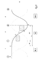
- step 107 If the type of the motion sequence determined in step 107 is AMA, AMM or MMA, it can be taken into account that a rail is stationary during N-1 and / or N + 1 picking. to spread the movement of the beam during the N duit "overflowing" on the N-1 or N + 1 pick.
- the beam is normally stopped during the N-1 pick, while it passes from position 1 to position 0 during the pick N. It is envisaged that the remarkable point P 1 corresponding to the starting position of movement for the smooth, as defined above with reference to the figure 2 , is moved within the N-1 pick to a point P ' 1 with the same ordinate y 1 as the point P 1 . This is obtained by defining a spreading parameter ⁇ of the movement of the bar from the N pick to the N-1 pick. This parameter ⁇ is determined iteratively by moving the point P ' 1 representative of the beginning of displacement with respect to the beginning of the pick N and verifying that this displacement remains compatible with the opening points P 4 and P 5 .
- the computer 26 determines a parameterized approximation function of the same type as the parameterized approximation function f N determined in the step 108 which satisfies the crossing constraints at the points P ' 1 , P 3 and P 2 and presents zero acceleration at point P ' 1 and a transition acceleration determined in step 106 at point P 2 .
- This approximation function is defined on the interval A 0 corresponding to the sum of 360 ° and of ⁇ .
- the point P ' 1 is moved to the left as long as the ordinate of the point P 4 remains compatible with the passage of a weft thread in the crowd.
- the value of the parameter ⁇ can be sought in a dichotomous manner or according to another approach, at the choice of the programmer of the computer 26.
- the value of the parameter ⁇ can initially be set at 10 °, so that the movement corresponding to the pick N is provided with an angular amplitude of 370 °.
- the computer 26 determines a parameterized approximation function according to an approach similar to that envisaged for step 108, but defined on the interval A 0 equal to 360 ° + ⁇ .
- the computer verifies the compatibility of this parameterized approximation function with the opening points P 4 and P 5 . If these conditions are met, the value of the offset parameter ⁇ is increased, for example by 10 °. In the opposite case, the value of this parameter is reduced by 50%, ie by 5 °.
- the displacement of the smooth corresponding to the N pick is thus performed on an angular amplitude A 0 equal to 360 ° + ⁇ .
- a 0 is 480 °.
- the beam In the case of an MMA type movement, the beam is moving at the N-1 and N picks, while it does not change position relative to the P M plane at the N + 1 pick.
- a first parameter ⁇ is used to spread the N pick to the N-1 pick while a second parameter ⁇ ' ⁇ is used to spread the N pick to the N + 1 pick.
- the operation is comparable to that mentioned with reference to the figure 5 and the displacement of the smooth corresponding to the pick N is performed on an angular amplitude A ⁇ equal to 360 ° + ⁇ + ⁇ ' ⁇ , ie about 515 ° in the example.
- the possibility of spreading the pick N on the previous and next picks N-1 and N + 1 makes it possible to shift the movement of the heddles on the picks during which there is no displacement planned, which is the case for the N-1 and N + 2 picks.
- the solid line corresponding to the curve C of displacement of a bar is offset with respect to the basic movement of the rails represented by the dashed lines, at the respective beginning and end of the N-1 and N + 2 picks.
- the displacements at the N-2 and N picks overflow at the N-1 pick, while the displacements at the N + 1 and N + 3 picks overflow the N + 2 pick.
- step 108 or step 110 the vector V N corresponding to the pick N is generated, in a step 111, in the form of a set of setpoint data which are supplied to the amplifier 16 of each actuator 6.
- the spreading parameter ⁇ can be determined taking into account the accelerations ⁇ N-2 / N-1 and ⁇ N + 1 / N + 2 .
- the movement of each frame of smooth is continuous and harmonious because the accelerations are relatively low and continuous.
- the calculation method used makes it possible to reduce constraints on the curves used. For example, the constraints at the opening points P 4 and P 5 are most often verified in steps 103 and 103 ', and not imposed.
- the setpoint vectors V N have been calculated for all the actuators 6, for a pick N, it is possible to calculate the same vectors for the pick N + 1.
- the transition accelerations ⁇ N-1 / N , ⁇ N + 1 / N and ⁇ N + 2 / N + 1 , between the N-1 and N, N and N + 1, N + 1 and N + 2 pickovers are already known from the calculation relating to the N pick, as well as the N and N + 1 movement sequences. It may be taken into account in steps 105 and 106.
- the knowledge of the remarkable points P 1 , P 2 , P 3 , P ' 1 and P' 2 and possibly the spreading parameter ⁇ of the pick N can be used to determine the law of this movement for the N + 1 pick.
- the calculator 26 When the calculator 26 has made these calculations for all the picks of an armor ratio, it returns to the first pick of this armor ratio and performs the same calculations again for all picks in the report. In this way, it is possible for him to take into account, during weaving, a modification of the crowd parameters since he accesses the memory 30 during these calculations. For example, if the user wishes to increase the amplitude Amp of the crowd on one of the frames 4, he can modify the set of data D 1 through the interface 32 and this value can be taken into account by the calculator 26 during the successive steps of determining the motion laws. The effective taking into account of the modification carried out by the user takes place as soon as possible, considering the delay which separates the transmission of the position instructions for the N pick at the beginning of this pick and the number of picks intervening by anticipation in the calculation of position instructions.
- the invention also makes it possible to envisage an application of the modification of the crowd parameters which does not result from the intervention of a user, such as the weaver, but from a real-time analysis based on the results.
- the amplitude Amp of the crowd can be decreased for all the picks of the armor. This decrease in amplitude is generally accompanied by a decrease in the forces in the transmission elements.
- the invention has been shown in the case of electric actuators 6 controlling smooth frames 4. It is also applicable to the case of actuators individually controlling smooth, as envisaged in EP-A-926,279 .
- the invention has been described in the case where an actuator is controlled individually according to a motion profile. Alternatively, several actuators can be controlled according to such a profile, for example if a pattern is reproduced over the width of a fabric. In this case, a set of setpoint data is generated for a group of actuators.
- the parameterized functions f k and L ( ⁇ ) are in the form of a cosine decomposition.
- Other types of functions can be envisaged.
- a parameterized function of polynomial type a parameterized function of spline type can be used. It also ensures that the amplitude of the crowd never exceeds the sum of the absolute values of the values defined at the terminals of each pick.
- the invention has been described in the case where the amplitude of the crowd remains constant from one pick to the other.
- the invention also allows the determination of positional instructions in the case where the amplitude of the crowd varies from one pick to the other.
- the computer determines the remarkable points as a function of the crowd parameters among which are the amplitudes.
- the other calculation steps can then take place as envisaged above.
- the computer 26 can transmit to the amplifiers 16 the parameters of the parameterized functions L ( ⁇ ), instead of the vectors V N , which allows the generation of the instructions at the level of the amplifiers 16 more precisely.
- a set of setpoint data is provided, for each pick and each actuator, by the amplifier 16 associated with each actuator 6.
Landscapes
- Engineering & Computer Science (AREA)
- Textile Engineering (AREA)
- Looms (AREA)
Abstract
Description
L'invention a trait à un procédé de commande des actionneurs électriques d'un dispositif de formation de la foule sur un métier à tisser.The invention relates to a method for controlling the electric actuators of a shedding device on a loom.
Dans le domaine de la formation de la foule sur métier à tisser, il est connu d'utiliser un actionneur électrique pour assurer le déplacement des lisses et former ainsi la foule dans laquelle sont insérés les fils de trame, lors de duites successives. Les lisses peuvent être montées sur des cadres, auquel cas l'actionneur peut être du type décrit dans
Ces actionneurs électriques doivent être commandés, pour chaque duite et en fonction de la ou des lisses qu'ils entraînent, avec des consignes de position qui leur permettent d'assurer le déplacement des lisses en respectant un certain nombre de paramètres, dits « paramètres de foule » et qui comprennent l'armure, l'amplitude de déplacement, un profil d'ouverture et un éventuel décalage par rapport au cycle métier ou à un plan médian de la foule.These electric actuators must be controlled, for each pick and depending on the or slats they lead, with position instructions that allow them to ensure the smooth movement of a number of parameters, called "parameters of crowd "and which include the armor, the range of motion, an aperture profile and any offset from the business cycle or a median plane of the crowd.
Il est connu de
Une alternative à cette solution connue consiste à calculer les consignes de position des différents actionneurs pour la totalité de l'armure, avant de commencer le tissage, puis de transmettre ces consignes à l'amplificateur associé à chaque actionneur, en dehors des phases de tissage. Des calculs relativement complexes peuvent être envisagés mais ceci ne permet pas de tenir compte de modifications de paramètres de foule en cours de tissage. En outre, des moyens de calcul de forte capacité doivent être utilisés.An alternative to this known solution is to calculate the position instructions of the various actuators for the entire armor, before starting the weave, then transmit these instructions to the amplifier associated with each actuator, outside the weaving phases. Relatively complex calculations can be envisaged but this does not allow to take into account changes in crowd parameters during weaving. In addition, high capacity calculation means must be used.
C'est à ces inconvénients qu'entend plus particulièrement remédier l'invention en proposant un nouveau procédé de commande qui permet de générer un ensemble de données de consigne, pour chaque duite et chaque actionneur ou groupe d'actionneurs, d'une façon optimisée.It is these drawbacks that the invention intends to remedy more particularly by proposing a new control method that makes it possible to generate a set of setpoint data, for each pick and each actuator or group of actuators, in an optimized manner. .
A cet effet, l'invention concerne un procédé de commande des actionneurs électriques d'un dispositif de formation de la foule sur un métier à tisser dans lequel un ensemble de données de consigne est généré, pour chaque duite et chaque actionneur ou groupe d'actionneurs, en tenant compte de paramètres de foule prédéterminés, caractérisé en ce qu'il comprend, pour une duite et un actionneur ou groupe d'actionneurs donnés, des étapes constituant à :
- a) déterminer, en fonction des paramètres de foule, des points remarquables d'un profil de mouvement d'une lisse entraînée par l'actionneur ou le groupe d'actionneurs, au moins pour la duite donnée, la duite précédente et la duite suivante ;
- b) déterminer une fonction paramétrée d'approximation du profil de mouvement qui passe par certains points remarquables, au moins pour la duite donnée, la duite précédente et la duite suivante ;
- c) calculer au moins quatre accélérations, à savoir :
- une première accélération de la lisse au début de son mouvement, à partir de la fonction d'approximation déterminée à l'étape b) pour la duite donnée,
- une deuxième accélération de la lisse à la fin de son mouvement, à partir de la fonction d'approximation déterminée à l'étape b) pour la duite donnée,
- une troisième accélération de la lisse à la fin de son mouvement, à partir de la fonction d'approximation déterminée à l'étape b) pour la duite précédente,
- une quatrième accélération de la lisse au début de son mouvement, à partir de la fonction d'approximation déterminée à l'étape b) pour la duite suivante,
- d) calculer une cinquième accélération, en fonction des première et troisième accélérations, et une sixième accélération, en fonction des deuxième et quatrième accélérations ;
- e) déterminer une loi de mouvement de la lisse pour la duite donnée, dont le profil passe par certains points remarquables et telle que l'accélération de la lisse au début de son mouvement est égale à la cinquième accélération et que l'accélération de la lisse à la fin de son mouvement est égale à la sixième accélération ;
- f) générer l'ensemble de données de consigne, pour la duite donnée et pour l'actionneur ou le groupe d'actionneurs, à partir de la loi de mouvement déterminée à l'étape e).
- a) determining, according to the shedding parameters, the remarkable points of a movement profile of a rail driven by the actuator or the group of actuators, at least for the given pick, the previous pick and the next pick ;
- b) determining a parameterized function of approximation of the motion profile passing through certain remarkable points, at least for the given pick, the previous pick and the next pick;
- c) calculate at least four accelerations, namely:
- a first acceleration of the bar at the beginning of its movement, from the approximation function determined in step b) for the given pick,
- a second acceleration of the smooth at the end of its movement, from the approximation function determined in step b) for the given pick,
- a third acceleration of the smooth at the end of its movement, from the approximation function determined in step b) for the previous pick,
- a fourth acceleration of the beam at the beginning of its movement, from the approximation function determined in step b) for the next pick,
- d) calculating a fifth acceleration, based on the first and third acceleration, and a sixth acceleration, based on the second and fourth acceleration;
- e) determining a law of movement of the rail for the given pick, whose profile passes through certain remarkable points and such that the acceleration of the rail at the beginning of its movement is equal to the fifth acceleration and that the acceleration of the smooth at the end of its movement is equal to the sixth acceleration;
- f) generating the set of setpoint data, for the given pick and for the actuator or the group of actuators, from the motion law determined in step e).
Grâce à l'invention, la prise en compte des accélérations au raccordement entre la duite donnée, la duite précédente et la duite suivante, permet de déterminer une loi de mouvement compatible avec un raccordement direct avec les lois de mouvement prévues pour la duite précédente et la duite suivante. Dans la mesure où la fonction paramétrée d'approximation et les opérations de calcul sont effectuées sur la base des points remarquables correspondant aux paramètres de foule, ces calculs peuvent avoir lieu de façon dynamique et tenir compte de modifications apportées en cours de tissage aux paramètres de foule.Thanks to the invention, taking into account the accelerations at the connection between the given pick, the previous pick and the next pick, makes it possible to determine a motion law compatible with a direct connection with the laws of movement provided for the previous pick and the next pick. Since the parameterized approximation function and the calculation operations are performed on the basis of the remarkable points corresponding to the crowd parameters, these computations can take place dynamically and take account of changes made during weaving to the parameters of the parameters. crowd.
Selon des aspects avantageux mais non obligatoires de l'invention, un tel procédé peut incorporer une ou plusieurs des caractéristiques suivantes, prises dans toute combinaison techniquement admissible :
- La cinquième accélération est égale à la moyenne des première et troisième accélérations et la sixième accélération est égale à la moyenne des deuxième et quatrième accélérations.
- Il est prévu des étapes antérieures à l'étape e) et consistant, g), à déterminer le type de séquence de mouvement de la lisse sur la duite précédente, la duite donnée et la duite suivante, au sein d'un groupe de huit mouvements type, h), si le type de séquence de mouvement déterminé à l'étape g) est tel que la lisse est déplacée pour la duite donnée, entre deux positions situées respectivement de part et d'autre d'un plan médian de la foule, et que la lisse n'est pas déplacée entre ces deux portions pour la duite précédente et/ou la duite suivante à déterminer au moins un paramètre d'étalement du mouvement de la lisse en tenant compte de certains au moins des points remarquables et, i), lorsque le paramètre d'étalement a été déterminé, déterminer au moins un nouveau point remarquable, en fonction des paramètres de foule et du paramètre d'étalement, alors que, lors de l'étape e), la loi de mouvement est déterminée en tenant compte du nouveau point remarquable et du paramètre d'étalement.
- Lors de l'étape h), le paramètre d'étalement est déterminé par tests successifs de l'influence de ce paramètre sur la compatibilité d'une loi de mouvement avec au moins un point remarquable.
- La compatibilité du paramètre d'étalement avec la loi de mouvement est testée avec un ou plusieurs points remarquables représentatifs d'une géométrie d'ouverture de foule, pour la duite et l'actionneur ou le groupe d'actionneurs concernés.
- Le paramètre d'étalement est représentatif de la portion supérieure à 360° de l'amplitude angulaire, par rapport à la rotation de l'arbre métier, sur laquelle a lieu le déplacement de la lisse pour la duite donnée.
- Des données représentatives des paramètres de foule sont stockées dans une mémoire dynamique à laquelle il est accédé lors de l'étape a), alors que ces données sont modifiables en cours de tissage.
- Lors de l'étape b), on détermine également une fonction paramétrée d'approximation du profil de mouvement qui passe par certains points remarquables pour une duite précédant de deux coups la duite donnée et une duite suivant de deux coups la duite donnée, alors que, lors de l'étape c), on calcule également :
- une septième accélération de la lisse au début de son mouvement à partir de la fonction d'approximation déterminée à l'étape b) pour la duite précédente,
- une huitième accélération de la lisse à la fin de son mouvement à partir de la fonction d'approximation déterminée à l'étape b) pour la duite suivante,
- une neuvième accélération de la lisse à la fin de son mouvement à partir de la fonction d'approximation déterminée à l'étape b) pour la duite précédant la duite précédente,
- une dixième accélération de la lisse au début de son mouvement à partir de la fonction d'approximation déterminée à l'étape b) pour la duite suivant la duite suivante,
alors qu'on calcule une onzième accélération, en fonction des septième et neuvième accélérations et une douzième accélération en fonction des huitième et dixième accélérations, et alors que, lors de l'étape e), on détermine la loi de mouvement pour la lisse donnée de telle sorte que l'accélération de la lisse pour la duite précédente en début de son mouvement est égale à la onzième accélération et que l'accélération de la lisse pour la duite suivante à la fin de son mouvement est égale à la douzième accélération. La onzième d'accélération est de préférence égale à la moyenne des septième et neuvième accélérations, alors que la douzième accélération est de préférence égale à la moyenne des huitième et dixième accélérations. Le paramètre d'étalement et/ou le nouveau point remarquable sont avantageusement déterminés en tenant compte des onzième et douzième accélérations. - Il est prévu des étapes j) et k) antérieures à l'étape c) et consistant, j), à vérifier la compatibilité de la fonction d'approximation avec des points remarquables représentatifs d'une géométrie d'ouverture de foule pour au moins la duite donnée, la duite précédente et la duite suivante, et, k), en cas d'incompatibilité détectée à l'étape j), à imposer ces points remarquables comme points de passage de la fonction d'approximation.
- La fonction paramétrée et/ou la loi de mouvement s'exprime sous la forme

- The fifth acceleration is equal to the average of the first and third acceleration and the sixth acceleration is equal to the average of the second and fourth acceleration.
- There are steps prior to step e) and consisting, g), to determine the type of motion sequence of the smooth on the previous pick, the given pick and the next pick, within a group of eight type movements, h), if the type of motion sequence determined in step g) is such that the beam is displaced for the given pick, between two positions located respectively on either side of a median plane of the crowd, and that the smooth is not moved between these two portions for the previous pick and / or the next pick to determine at least one spreading parameter of the movement of the rail taking into account at least some of the remarkable points and i), when the spreading parameter has been determined, determining at least one new remarkable point, depending on the crowd parameters and the spreading parameter, whereas, during step e), the motion law is determined taking into account the new remarkable point and the spreading parameter.
- During step h), the spreading parameter is determined by successive tests of the influence of this parameter on the compatibility of a motion law with at least one remarkable point.
- The compatibility of the spreading parameter with the motion law is tested with one or more remarkable points representative of a shedding geometry, for the pick and the actuator or group of actuators concerned.
- The spreading parameter is representative of the portion greater than 360 ° of the angular amplitude, relative to the rotation of the business tree, on which the displacement of the bar for the given pick takes place.
- Data representative of the crowd parameters are stored in a dynamic memory to which it is accessed during step a), while these data are modifiable during weaving.
- During step b), a parameterized function of approximation of the motion profile which passes through certain remarkable points for a pick preceding two shots at a given pick and a pick of two shots at a given pick is also determined, whereas during step c), the following are also calculated:
- a seventh acceleration of the smooth at the beginning of its movement from the approximation function determined in step b) for the previous pick,
- an eighth acceleration of the smooth at the end of its movement from the approximation function determined in step b) for the next pick,
- a ninth acceleration of the smooth at the end of its movement from the approximation function determined in step b) for the pick preceding the previous pick,
- a tenth acceleration of the stringer at the beginning of its movement from the approximation function determined in step b) for the pick following the next pick,
while calculating an eleventh acceleration, as a function of the seventh and ninth accelerations and a twelfth acceleration as a function of the eighth and tenth accelerations, and whereas, during step e), the motion law for the given smooth is determined so that the acceleration of the smooth for the previous pick at the beginning of its movement is equal to the eleventh acceleration and the acceleration of the smooth for the next pick at the end of its movement is equal to the twelfth acceleration. The eleventh acceleration is preferably equal to the seventh and ninth average accelerations, while the twelfth acceleration is preferably equal to the average of the eighth and tenth acceleration. The spread parameter and / or the new remarkable point are advantageously determined taking into account the eleventh and twelfth accelerations. - Steps j) and k) prior to step c) and consisting of j) are provided to check the compatibility of the approximation function with remarkable points representative of a crowd opening geometry for at least the given duit, the previous pick and the next pick, and, k), in case of incompatibility detected in step j), to impose these remarkable points as passing points of the approximation function.
- The parameterized function and / or the motion law is expressed in the form
L'invention sera mieux comprise et d'autres avantages de celle-ci apparaîtront plus clairement à la lumière de la description qui va suivre d'un mode de réalisation d'un procédé de commande conforme à son principe, donnée uniquement à titre d'exemple et faite en référence aux dessins annexés dans lesquels :
- la
figure 1 est une représentation schématique de principe d'un métier à tisser avec lequel peut être mise en oeuvre l'invention ; - la
figure 2 est une représentation schématique d'un profil de mouvement d'une lisse au cours d'une duite, sur le métier de lafigure 1 ; - la
figure 3 est une représentation schématique analogue à lafigure 2 , pour un autre profil de mouvement ; - la
figure 4 est un exemple de représentation des variations de positon d'une lisse au cours du temps sur plusieurs duites ; - la
figure 5 est une représentation schématique de principe, comparable à lafigure 4 montrant un mouvement de lisses sur trois duites successives ; - la
figure 6 est une vue analogue à lafigure 5 pour un autre mouvement de lisses ; et - la
figure 7 est un ordinogramme d'un procédé conforme à l'invention.
- the
figure 1 is a schematic representation of a weaving machine with which the invention can be implemented; - the
figure 2 is a schematic representation of a movement profile of a smooth during a pick, on the craft of thefigure 1 ; - the
figure 3 is a schematic representation similar to thefigure 2 , for another movement profile; - the
figure 4 is an example of representation of positron variations of a smooth over time over several picks; - the
figure 5 is a schematic representation of principle, comparable to thefigure 4 showing a movement of smooth on three successive picks; - the
figure 6 is a view similar to thefigure 5 for another movement of smooth; and - the
figure 7 is a flow chart of a method according to the invention.
Le métier à tisser 2 représenté schématiquement et de façon partielle à la
Chaque actionneur 6 est piloté par un amplificateur associé 16 qui gère son alimentation en courant, en fonction de la position du rotor non représenté de cet actionneur 6 mesurée par un codeur 18 et en fonction d'une consigne de position qui lui provient sous la forme d'un signal électronique S1 de la part d'un contrôleur de ratière 20 qui est commun pour tous les actionneurs 6.Each
Le contrôleur de ratière 20 est connecté au contrôleur 22 du métier 2 au moyen d'une liaison filaire 24 qui permet l'échange d'informations relatives au mode de fonctionnement du métier 2 et du dispositif de formation de la foule comprenant, entre autres, les actionneurs 6 et les cadres 4.The
Le contrôleur de ratière 20 comprend un calculateur 26 qui est capable d'émettre les signaux S1 et qui est relié par la liaison 24 au contrôleur de métier 22. Le calculateur 26 est également relié à un capteur 28 qui lui fournit la position du métier 2 dans son cycle. Le capteur 28 est, par exemple, un résolveur couplé à l'arbre principal du métier 2. Le contrôleur de ratière 20 est équipé d'une mémoire 30 dans laquelle sont stockés, sous la forme d'un ensemble de données D1, les paramètres de foule à utiliser, ces paramètres comprenant notamment l'armure, les amplitudes de déplacement des cadres, les profils à suivre et les éventuels décalages temporels par rapport à une position médiane.The
Le contrôleur 20 comprend également une interface utilisateur 32 qui inclut des moyens d'affichage 321 et des moyens de saisie 322 permettant de modifier, entre autres, les paramètres de foule stockés dans la mémoire 30. Les éléments 30 et 32 sont reliés au calculateur 26 par des liaisons filaires 34 et 36.The
On considère une duite d'ordre N au sein d'une armure, qui peut comprendre un grand nombre de duites. Ce nombre de duites est appelé rapport d'armure. La duite précédant cette duite donnée d'ordre N est la duite d'ordre N-1 et la duite précédant la duite donnée N de deux coups est la duite d'ordre N-2. La duite suivant la duite donnée d'ordre N est la duite d'ordre N+1, alors que la duite suivant de deux coups la duite donnée d'ordre N est la duite d'ordre N+2. Pour chaque duite donnée N, la consigne de position pour la commande d'un actionneur 6 est transmise sous la forme d'un vecteur VN de trente-trois points qui définit une succession, de trente-deux intervalles réguliers, de positions angulaires du rotor de cet actionneur sur un cycle métier. Un vecteur VN est transmis à chaque amplificateur 16 en tant que partie du signal S1 émis par le calculateur 26 vers cet amplificateur. Chaque amplificateur 16 est capable d'interpoler les positions intermédiaires du rotor de l'actionneur qu'il alimente, entre deux positions données par le vecteur VN qui lui est transmis par le calculateur 26.N-order picking is considered within an armor, which can include a large number of picks. This number of picks is called the armor ratio. The duit preceding this given duce of order N is the duity of order N-1 and the duity preceding the given duity N of two moves is the duity of order N-2. The pick following the given pick of order N is the pick of order N + 1, while the next pick of two moves the given pick of order N is the pick of order N + 2. For each given pick N, the position setpoint for the control of an
Un cycle métier correspond habituellement à une rotation de 360° de l'arbre principal du métier 2.A business cycle usually corresponds to a 360 ° rotation of the main tree of
Le vecteur VN transmis à chaque amplificateur 16 pour une duite N comprend donc un ensemble de données de consigne qu'il importe de déterminer de la meilleure façon pour obtenir un tissage harmonieux, avec des accélérations optimisées. La détermination par calcul de chaque vecteur ou ensemble de données de consigne VN est réalisé par le calculateur 26.The vector V N transmitted to each
La duite N s'étend sur une plage angulaire de l'ordre de 360° de rotation de l'arbre métier. On note θ1 la position de l'arbre métier au début de la duite N et θ2 sa position à la fin de la duite. En pratique, la valeur de θ1 est égale à la valeur de θ2, à environ 360° près. La
On note P4 un point représentatif de l'ouverture nécessaire de la foule pour le passage d'un fil de trame dans la foule sur une course angulaire partant de la position angulaire initiale θ1. On note P5 un point représentatif de l'ouverture nécessaire de la foule pour le passage d'un fil de trame sur une course angulaire aboutissant à la position angulaire finale θ2. Les points P4 et P5 sont définis par leurs abscisses θ4 et θ5 et leurs ordonnées y4 et y5 qui sont respectivement strictement positive et strictement négative. La valeur de y4 est comprise entre la valeur de Δ1 et la valeur de y1.Note P 4 a representative point of the necessary opening of the shed for the passage of a weft yarn in the crowd on an angular stroke starting from the initial angular position θ 1 . We note P 5 a representative point of the necessary opening of the shed for the passage of a weft yarn on an angular stroke leading to the final angular position θ 2 . The points P 4 and P 5 are defined by their abscissas θ 4 and θ 5 and their ordinates y 4 and y 5 which are respectively strictly positive and strictly negative. The value of y 4 lies between the value of Δ 1 and the value of y 1 .
La courbe C selon laquelle se déplace une lisse au cours d'une duite N peut être caractérisée grâce aux points P1 à P5 qui sont des points remarquables correspondant à des positions spécifiques de la lisse, respectivement au début, à la fin, au milieu de son déplacement ainsi que dans deux positions découlant du profil d'ouverture recherché pour le passage d'un fil de trame.The curve C along which a rail moves during a pick N can be characterized by the points P 1 to P 5 which are remarkable points corresponding to specific positions of the rail, respectively at the beginning, at the end, at the middle of its displacement as well as in two positions resulting from the desired opening profile for the passage of a weft thread.
Les abscisses et ordonnées respectives des points remarquables P1 à P5 sont issues des données de l'ensemble de données D1 stockées dans la mémoire 30.The respective abscissae and ordinates of the remarkable points P 1 to P 5 come from the data of the set of data D 1 stored in the
Lorsqu'il doit déterminer le vecteur VN correspondant à une duite N pour un actionneur 6, le calculateur 26 accède, dans une première étape 101 du procédé représentée à la
En pratique, le calculateur 26 récupère dans l'ensemble de données D1 certains paramètres de foule tels que l'amplitude de foule Amp, le décalage vertical souhaité Δ1 au point intermédiaire P3 et l'ouverture souhaitée pour le passage des fils de trame. Sur la base de ces données, le calculateur 26 peut calculer les ordonnées y1, y2 et y3 et les abscisses et ordonnées θ4, θ5, y4, y5 des points P4 et P5. Dans la mesure où, par défaut, chaque duite s'étale sur un cycle métier de 360° de rotation de l'arbre principal du métier, les abscisses des points extrêmes P1, P2 et du point intermédiaire P3 sont connues.In practice, the
Dans une étape 102, le calculateur 26 détermine une fonction paramétrée fk d'approximation de la courbe C en fonction de l'angle métier θ, pour chacune des duites N-2 à N+2, en tenant compte des contraintes représentées par les points P1k à P3k, k valant de N-2 à N+2.In a
A titre d'exemple, la fonction paramétrée fk peut prendre la forme d'une décomposition en cosinus telle que 
où m est un entier qui est adapté au nombre de contraintes à respecter en fonction du nombre de points remarquables, ω est la pulsation dont la valeur est égale à Π/360° lorsque θ est exprimé en degrés.where m is an integer which is adapted to the number of constraints to respect according to the number of remarkable points, ω is the pulsation whose value is equal to Π / 360 ° when θ is expressed in degrees.
La détermination de la fonction paramétrée fk consiste à calculer les coefficients a0, a1, ..., am en résolvant un système dont le nombre d'équations est égal au nombre de contraintes à respecter, c'est-à-dire égal à m + 1. Dans le cas présent, on compte trois contraintes correspondant chacune à un des points P1k à P3k.The determination of the parameterized function f k consists in calculating the coefficients a 0 , a 1 , ..., a m by solving a system whose number of equations is equal to the number of constraints to be respected, that is to say say equal to m + 1. In the present case, there are three constraints each corresponding to one of the points P 1k to P 3k .
Dans l'hypothèse ci-dessus où la fonction paramétrée fk est une fonction périodique dont la demi-période s'étend entre les deux points extrêmes P1 et P2, la théorie de Fourrier fournit des outils de résolution du système d'équation qui traduit la réalisation des contraintes aux différents points P1 à P3.In the above hypothesis, where the parameterized function f k is a periodic function whose half-period extends between the two extreme points P 1 and P 2 , the Fourier theory provides tools for solving the equation system. which translates the realization of the constraints at the different points P 1 to P 3 .
La détermination de cette fonction paramétrée y = fk(θ) a lieu pour la duite N, ainsi que pour chacune des deux duites précédentes, N-2 et N-1, et chacune des deux duites suivantes, N+1 et N+2.The determination of this parameterized function y = f k (θ) takes place for the pick N, as well as for each of the two previous picks, N-2 and N-1, and each of the two picks N + 1 and N + 2.
En variante, la fonction fk peut être une fonction polynomiale du type ![]()
où m est égal au nombre de contraintes à respecter moins une.As a variant, the function f k can be a polynomial function of the type ![]()
where m is equal to the number of constraints to respect minus one.
L'étape 102 est également applicable au cas où, au cours de la duite N, la lisse reste du même côté du plan médian de la foule PM, comme représenté à la
Comme dans le cas de la
Lors de l'étape 102, seuls les points P1, P2 et P3 sont considérés comme imposés pour la détermination des fonctions paramétrées d'approximation fk. Lorsque ces fonctions fk ont été déterminées pour chacune des duites N-2, N-1, N, N+1 et N+2, on vérifie si la courbe construite à partir de chacune de ces fonctions paramétrées est compatible avec les positions des points P4k et P5k telles qu'elles découlent des paramètres de foule, pour chacune de ces duites. En d'autres termes, on vérifie, pour chacune des valeurs de k entre N-2 et N+2, qu'à l'abscisse θ4 ou θs de chaque point d'ouverture P4 ou P5, l'ordonnée y4 ou y5 calculée grâce à la fonction paramétrée d'approximation fk est plus grande en valeur absolue que celle du point d'ouverture correspondant P4k ou P5k. Ceci a lieu lors d'une étape 103. Pour toutes les duites de N-2 à N+2 pour lesquelles le résultat de cette comparaison est négatif, on passe à une étape 104 au cours de laquelle les points P4k et P5k sont imposés comme valeurs de contrainte pour la détermination des fonctions paramétrées d'approximation fk lors de l'étape 102.In
Le nombre d'équations disponibles qui traduisent chacune une contrainte est alors de cinq. La fonction paramétrée est du type 
La théorie de Fourrier fournit les outils pour déterminer les paramètres a0 à a4.Fourier's theory provides the tools to determine the parameters a 0 to a 4 .
Après une vérification supplémentaire 103, on parvient alors dans une étape 105 au cours de laquelle le calculateur 26 calcule l'accélération d'une lisse au début de la duite N, en considérant que cette lisse suit la trajectoire déterminée par la fonction paramétrée fN. En effet, sur la base de l'équation 1) ci-dessus, il est possible de calculer la vitesse de déplacement de la lisse en un point comme étant égale à 
Sur la base de l'équation 3, il est possible de calculer l'accélération en un point de la duite N comme étant égale à 
Cette opération est effectuée pour chacune des fonctions fk correspondant à l'une des duites N-2, N-1, N, N+1 et N+2.This operation is performed for each of the functions f k corresponding to one of the picks N-2, N-1, N, N + 1 and N + 2.
Ceci permet de considérer l'accélération γ(N-2)F à la fin de la duite N-2 qui est égale à l'accélération pour l'abscisse θ2 correspondant à la fonction paramétrée fN-2 utilisée pour la duite N-2.This makes it possible to consider the acceleration γ (N-2) F at the end of the N-2 pick which is equal to the acceleration for the abscissa θ 2 corresponding to the parameterized function f N - 2 used for the pick N -2.
De la même façon, on peut déterminer l'accélération γ(N-1)D au début de la duite N-1 correspondant à l'accélération pour l'abscisse θ1 pour la fonction fN-1 utilisée pour la duite N-1, l'accélération γ(N-1)F à la fin de la duite N-1, l'accélération γND au début de la duite N à partir de la fonction fN, l'accélération γNF à la fin de la duite N, l'accélération γ(N+1)D au début de la duite N+1 à partir de la fonction fN+1, l'accélération γ(N+1)F à la fin de la duite N+1 et l'accélération γ(N+2)D au début de la duite N+2, à partir de la fonction fN+2.In the same way, it is possible to determine the acceleration γ (N-1) D at the beginning of the N-1 pick corresponding to the acceleration for the abscissa θ 1 for the function f N-1 used for the N-1 pick. 1, the acceleration γ (N-1) F at the end of the pick N-1, the acceleration γ ND at the beginning of the pick N from the function f N , the acceleration γ NF at the end of the pick N, the acceleration γ (N + 1) D at the beginning of the N + 1 pick from the function f N + 1 , the acceleration γ (N + 1) F at the end of the N +
Si l'accélération à la fin d'une duite définie ci-dessus est égale à l'accélération au début de la duite suivante, alors il y a raccordement sans à-coups entre les trajectoires obtenues par les fonctions paramétrées d'approximation fk et fk+1, ce qui est tout à fait positif. Dans le cas contraire, on peut considérer la moyenne entre l'accélération à la fin d'une duite et l'accélération au début de la duite suivante, cette moyenne étant égale à la demi-somme de ces accélérations.If the acceleration at the end of a pick defined above is equal to the acceleration at the beginning of the next pick, then there is junction smoothly between the trajectories obtained by the parameterized approximation functions f k and f k + 1 , which is quite positive. In the opposite case, we can consider the average between the acceleration at the end of a pick and the acceleration at the beginning of the next pick, this average being equal to the half-sum of these accelerations.
On définit ainsi une accélération moyenne à la fin de la duite N-2 et au début de la duite N-1 comme étant égale à γN-2/N-1 = γ(N-2)F + γ(N-1)D)/2.Thus, a mean acceleration at the end of the N-2 pick and at the beginning of the N-1 pick is defined as being equal to γ N-2 / N-1 = γ (N - 2) F + γ (N-1) ) D ) / 2.
On définit de la même façon les accélérations suivantes :
- accélération moyenne à la fin de la duite N-1 et au début de la duite N :

- accélération moyenne à la fin de la duite N et au début de la duite N+1 :

- accélération moyenne à la fin de duite N+1 et au début de la duite N+2 :

- average acceleration at the end of the N-1 pick and at the beginning of the N pick:
- average acceleration at the end of the N pick and at the beginning of the N + 1 pick:
- average acceleration at the end of the N + 1 pick and at the beginning of the N + 2 pick:
Si les accélérations dont on fait la moyenne sont nulles, alors leur moyenne est nulle. En tant que moyennes, les accélérations γN-2/N-1, γN-1/N, γN/N+1 et γN+1/N+2 dépendent des accélérations γ(N-2)F, γ(N-1)D ··· γ(N+1)D. En variante, les accélérations γN-2/N-1, γN-1/N, γN/N+1 et γN+1/N+2 peuvent dépendre des accélérations γ(N-2)F à γ(N+2)D d'une autre façon.If the accelerations averaged are zero, then their average is zero. As averages, the accelerations γ N-2 / N-1 , γ N-1 / N , γ N / N + 1 and γ N + 1 / N + 2 depend on the accelerations γ (N-2) F , γ (N-1) D ··· γ (N + 1) D. As a variant, the accelerations γ N-2 / N-1 , γ N-1 / N , γ N / N + 1 and γ N + 1 / N + 2 can depend on the accelerations γ (N - 2) F to γ ( N + 2) D in another way.
Les calculs de ces accélérations γN-2/N-1 à γN+1/N+2, à la transition entre deux duites successives sont effectués au cours d'une étape 106 par le calculateur 26.The computations of these accelerations γ N-2 / N-1 at γ N + 1 / N + 2 , at the transition between two successive picks are carried out during a
Au cours d'une étape ultérieure 107, on détermine le type de séquence de mouvement correspondant à la succession des trois duites centrées sur la duite N, à savoir les duites N-1, N et N+1. En effet, on peut considérer qu'il existe un mouvement M au cours d'une duite si une lisse passe d'une position située au-dessus du plan médian PM à une position située en-dessous, ou réciproquement. Si la valeur 1 correspond à une position haute de la lisse et la valeur 0 correspond à une position basse, on considère qu'il y a mouvement si l'armure passe de 1 à 0 ou de 0 à 1. A contrario, on considère qu'il y a arrêt A pendant cette duite si l'armure reste à 1 ou à 0, ceci pouvant correspondre à un mouvement de fermeture du pas, comme expliqué ci-dessus en référence à la
On dénombre ainsi huit types de séquence de mouvements pour trois duites successives, à savoir :
- AAA correspondant aux armures 0000 et 1111,
- AAM correspondant aux armures 0001 et 1110,
- AMA correspondant aux armures 0011 et 1100,
- AMM correspondant aux armures 0010 et 1101,
- MAA correspondant aux armures 0111 et 1000,
- MAM correspondant aux armures 0110 et 1001,
- MMA correspondant aux armures 0100 et 1011, et
- MMM correspondant aux armures 0101 et 1010.
- AAA corresponding to armor 0000 and 1111,
- AAM corresponding to the armor 0001 and 1110,
- AMA corresponding to the armor 0011 and 1100,
- AMM corresponding to the armor 0010 and 1101,
- MAA corresponding to 0111 and 1000 armor,
- MAM corresponding to armor 0110 and 1001,
- MMA corresponding to the armor 0100 and 1011, and
- MMM corresponding to 0101 and 1010 armor.
Les types de séquences de mouvement AMA, AMM et MMA présentent la particularité que le mouvement M qui a lieu à la duite N est contigu à au moins un arrêt, au cours d'une des duites N-1 ou N+1.The types of motion sequences AMA, AMM and MMA have the particularity that the movement M which takes place at the N pick is contiguous with at least one stop, during one of the picks N-1 or N + 1.
Lorsque le type de la séquence de mouvement a été déterminé à l'étape 107, deux cas sont considérés : soit cette séquence de mouvement est de type AMA, AMM ou MMA, soit elle est d'un type différent.When the type of the motion sequence has been determined in
Si la séquence de mouvement déterminée à l'étape 107 est d'un type autre que AMA, AMM ou MMA, le calculateur 26 passe à une étape 108 au cours de laquelle il détermine une loi de mouvement paramétrée L qui donne l'abscisse y d'une lisse en fonction de l'angle θ au cours de la duite N, en passant par les points remarquables P1 à P3, en respectant les contraintes d'ouverture au P4 et P5 et les accélérations de transition déterminées à l'étape 106.If the motion sequence determined in
Le calculateur 26 procède selon une approche similaire à celle adoptée pour l'étape 102, avec des contraintes supplémentaires. Un premier calcul est effectué pour déterminer les paramètres d'une loi d'approximation qui passe par les points remarquables P1N, P2N et P3N et présente les accélérations calculées à l'étape 106. Ensuite, les ordonnées calculées aux abscisses des points P4N et P5N sont comparées aux valeurs y4 et y5. Si ces coordonnées calculées sont supérieures en valeur absolue aux valeurs y4 et y5, alors la loi d'approximation paramétrée y = L(θ) convient et est retenue. Dans le cas contraire, un nouveau calcul des paramètres de la loi d'approximation est effectué en imposant le passage par les points P1N à P5N et le respect des accélérations calculées à l'étape 106.The
La loi de mouvement paramétrée L(θ) peut être de la forme 
Les coefficients a0 à a6 peuvent être déterminés puisque ils sont les solutions d'un système de sept équations dont chacune exprime la réalisation d'une contrainte.The coefficients a 0 to a 6 can be determined since they are the solutions of a system of seven equations, each of which expresses the realization of a constraint.
Cette partie ou procédé est effectuée lors d'étapes 103' et 104' qui sont comparables aux étapes 103 et 104, sauf que les vérifications et calculs sont effectués seulement par la duite N.This part or process is performed during steps 103 'and 104' which are comparable to
Si le type de la séquence de mouvement déterminée à l'étape 107 est AMA, AMM ou MMA, on peut tenir compte du fait qu'une lisse est à l'arrêt au cours de la duite N-1 et/ou N+1 pour étaler le mouvement de la lisse lors de la duite N en « débordant » sur la duite N-1 ou N+1.If the type of the motion sequence determined in
Dans le cas d'un mouvement de type AMM représenté à la
Par exemple, la valeur du paramètre Δθ peut être fixée initialement à 10°, de sorte que le mouvement correspondant à la duite N est prévu avec une amplitude angulaire de 370°. Le calculateur 26 détermine alors une fonction paramétrée d'approximation selon une approche analogue à celle envisagée pour l'étape 108, mais définie sur l'intervalle A0 égal à 360° + Δθ. Le calculateur vérifie alors la compatibilité de cette fonction paramétrée d'approximation avec les points d'ouverture P4 et P5. Si ces conditions sont respectées, on augmente la valeur du paramètre de décalage Δθ, par exemple de 10°. Dans le cas contraire, on diminue la valeur de ce paramètre de 50%, soit de 5°. On peut procéder ainsi selon plusieurs occurrences, afin de déterminer, au cours d'une étape 109, une valeur optimale du paramètre Δθ pour lesquelles il est satisfait aux conditions de passage aux points d'ouverture P4 et P5, alors que la valeur de Δθ est maximale. La loi de mouvement y = L(θ) est alors calculée, lors d'une étape ultérieure 110, en tenant compte du paramètre non nul Δθ déterminé au cours de l'étape 109.For example, the value of the parameter Δθ can initially be set at 10 °, so that the movement corresponding to the pick N is provided with an angular amplitude of 370 °. The
Le déplacement de la lisse correspondant à la duite N est ainsi effectué sur une amplitude angulaire A0 égale à 360°+ Δθ. Dans l'exemple représenté à la
Dans le cas d'un mouvement de type MMA, la lisse est en mouvement aux duites N-1 et N, alors qu'elle ne change pas de position par rapport au plan PM à la duite N+1. D'une façon analogue au cas d'un mouvement de type AMM, le calculateur 26 détermine une loi de mouvement paramétrée y = L(θ) et la valeur d'un paramètre de décalage Δθ correspondant alors à l'étalement, sur la duite N+1, du mouvement de la lisse à la duite N.In the case of an MMA type movement, the beam is moving at the N-1 and N picks, while it does not change position relative to the P M plane at the N + 1 pick. In a manner analogous to the case of a movement of the AMM type, the
Dans l'exemple de la
Dans ce cas, deux nouveaux points remarquables P'1 et P'2 sont définis, respectivement avant le début de la plage angulaire de 360° correspondant normalement à la duite N et après cette plage. Les points P'1 et P'2 sont pris en compte pour la détermination de la loi de mouvement y=L(θ) à l'étape 110.In this case, two new remarkable points P ' 1 and P' 2 are defined, respectively before the beginning of the angular range of 360 ° normally corresponding to the pick N and after this range. The points P ' 1 and P' 2 are taken into account for the determination of the motion law y = L (θ) in
Comme représenté à la
Après l'étape 108 ou l'étape 110, le vecteur VN correspondant à la duite N est généré, lors d'une étape 111, sous la forme d'un ensemble de données de consigne qui sont fournies à l'amplificateur 16 de chaque actionneur 6.After
Selon une variante non représentée de l'invention, le paramètre d'étalement Δθ peut être déterminé en tenant compte des accélérations γN-2/N-1 et γN+1/N+2.According to a not represented variant of the invention, the spreading parameter Δθ can be determined taking into account the accelerations γ N-2 / N-1 and γ N + 1 / N + 2 .
Grâce à l'invention, le mouvement de chaque cadre de lisses est continu et harmonieux car les accélérations sont relativement faibles et continues. Quel que soit la séquence de mouvement de la duite, la loi de mouvement y = L(θ) présente des accélérations continues aux bornes de la duite. En effet, en permettant l'étalement des phases de mouvement sur les duites d'arrêt, pour certains types de séquence de mouvement, les accélérations nécessaires à la mise en mouvement ou à l'arrêt de chaque cadre diminuent. En outre, le mode de calcul utilisé permet de réduire les contraintes sur les courbes utilisées. Par exemple, les contraintes aux points d'ouverture P4 et P5 sont le plus souvent vérifiées aux étapes 103 et 103', et non pas imposées.Thanks to the invention, the movement of each frame of smooth is continuous and harmonious because the accelerations are relatively low and continuous. Whatever the movement sequence of the pick, the motion law y = L (θ) has continuous accelerations across the pick. In fact, by allowing the movement phases to be spread on the stop picks, for certain types of movement sequence, the accelerations necessary for the setting in motion or the stopping of each frame decrease. In addition, the calculation method used makes it possible to reduce constraints on the curves used. For example, the constraints at the opening points P 4 and P 5 are most often verified in
Lorsque les vecteurs de consigne VN ont été calculés pour tous les actionneurs 6, pour une duite N, on peut passer au calcul des mêmes vecteurs pour la duite N+1. Dans ce cas, il peut être tenu compte des calculs déjà effectués pour les analyses de la duite N. Par exemple, les accélérations de transition γN-1/N, γN+1/N et γN+2/N+1, entre les duites N-1 et N, N et N+1, N+1 et N+2 sont déjà connues du calcul relatif à la duite N, de même que les séquences de mouvement des duites N et N+1. Il peut en être tenu compte aux étapes 105 et 106. A cette occasion, la connaissance des points remarquables P1, P2, P3, P'1 et P'2 et éventuellement du paramètre d'étalement Δθ de la duite N peut être utilisée pour déterminer la loi de ce mouvement pour la duite N+1.When the setpoint vectors V N have been calculated for all the
Lorsque le calculateur 26 a procédé à ces calculs pour toutes les duites d'un rapport d'armure, il revient à la première duite de ce rapport d'armure et effectue à nouveau les mêmes calculs pour toutes les duites du rapport. De cette façon, il lui est possible de tenir compte, en cours de tissage, d'une modification des paramètres de foule puisqu'il accède à la mémoire 30 au cours de ces calculs. Par exemple, si l'utilisateur désire augmenter l'amplitude Amp de la foule sur l'un des cadres 4, il peut modifier l'ensemble de données D1 à travers l'interface 32 et cette valeur peut être prise en compte par le calculateur 26 au cours des étapes successives de détermination des lois de mouvement. La prise en compte effective de la modification effectuée par l'utilisateur a lieu dès que possible, compte tenu du délai qui sépare la transmission des consignes de position pour la duite N au début de cette duite et du nombre de duites intervenant par anticipation dans le calcul des consignes de position.When the
L'invention permet également d'envisager une mise en application de la modification des paramètres de foule qui ne résulte pas de l'intervention d'un utilisateur, tel que le tisseur, mais d'une analyse conduite en temps réel à partir des résultats de tissage, au sein du contrôleur de métier 22 ou du contrôleur de ratière 20. Par exemple, en cas de détection d'un taux d'arrêt de trame important, le contrôleur de métier 22 peut augmenter l'ouverture aux points P4 et P5, c'est-à-dire la valeur absolue des abscisses y4 et y5, ce qui est pris en compte à un stade ultérieur, lors du prochain calcul de la loi de mouvement y=L(θ) pour la duite correspondante, sans arrêt du métier 2.The invention also makes it possible to envisage an application of the modification of the crowd parameters which does not result from the intervention of a user, such as the weaver, but from a real-time analysis based on the results. for example, in the event of detection of a large frame stop rate, the
Il est également possible au contrôleur 20 de tenir compte du niveau de contrainte dans les bielles 8, tel que détecté par des cellules 10 et transmis au conditionneur 14, pour modifier en cours de tissage les paramètres de foule de l'ensemble de données D1, de manière à générer des lois de mouvement paramétrées y=L(θ) qui entraînent un abaissement de ce niveau de contrainte. Par exemple, l'amplitude Amp de la foule peut être diminuée pour l'ensemble des duites de l'armure. Cette diminution de l'amplitude s'accompagne généralement d'une baisse des efforts dans les éléments de transmission.It is also possible for the
L'invention a été décrite dans le cas où la duite N-2 et la duite N+2 sont prises en compte, en plus des duites N-1 et N+1, pour la détermination de la loi de mouvement y=L(θ) correspondant à la duite N. Selon une version simplifiée de l'invention, seules les duites N-1, N et N+1 peuvent être prises en compte à ce stade.The invention has been described in the case where the N-2 pick and the N + 2 pick are taken into account, in addition to the N-1 and N + 1 picks, for the determination of the motion law y = L ( θ) corresponding to the N pick. According to a simplified version of the invention, only the N-1, N and N + 1 picks can be taken into account at this stage.
L'invention a été représentée dans le cas d'actionneurs électriques 6 commandant des cadres de lisses 4. Elle est également applicable au cas d'actionneurs commandant individuellement des lisses, comme envisagé dans
L'invention a été décrite dans le cas où un actionneur est commandé individuellement en fonction d'un profil de mouvement. En variante, plusieurs actionneurs peuvent être commandés en fonction d'un tel profil, par exemple si un motif se reproduit sur la largeur d'un tissu. Dans ce cas, un ensemble de données de consigne est généré pour un groupe d'actionneurs.The invention has been described in the case where an actuator is controlled individually according to a motion profile. Alternatively, several actuators can be controlled according to such a profile, for example if a pattern is reproduced over the width of a fabric. In this case, a set of setpoint data is generated for a group of actuators.
L'invention a été décrite dans le cas où, pour k entre N-2 et N+2, les fonctions paramétrée fk et L(θ) se présentent sous la forme d'une décomposition en cosinus. D'autres types de fonctions peuvent être envisagés. En plus du cas déjà évoqué d'une fonction paramétrée de type polynomial, une fonction paramétrée de type spline peut être utilisée. Elle permet en outre de garantir que l'amplitude de la foule ne dépasse jamais la somme des valeurs absolues des valeurs définies aux bornes de chaque duite.The invention has been described in the case where, for k between N-2 and N + 2, the parameterized functions f k and L (θ) are in the form of a cosine decomposition. Other types of functions can be envisaged. In addition to the case already mentioned of a parameterized function of polynomial type, a parameterized function of spline type can be used. It also ensures that the amplitude of the crowd never exceeds the sum of the absolute values of the values defined at the terminals of each pick.
L'invention a été décrite dans le cas où l'amplitude de la foule reste constante d'une duite à l'autre. L'invention permet également la détermination de consignes de position dans le cas où l'amplitude de la foule varie d'une duite à l'autre. Dans ce cas, lors de l'étape 101, le calculateur détermine les points remarquables en fonction des paramètres de foule parmi lesquels se trouvent les amplitudes. Les autres étapes de calcul peuvent alors avoir lieu comme envisagé ci-dessus.The invention has been described in the case where the amplitude of the crowd remains constant from one pick to the other. The invention also allows the determination of positional instructions in the case where the amplitude of the crowd varies from one pick to the other. In this case, during
Dans le cas où des calculateurs intégrés aux amplificateurs 16 sont assez performants, le calculateur 26 peut transmettre aux amplificateurs 16 les paramètres des fonctions paramétrées L(θ), au lieu des vecteurs VN, ce qui permet la génération des consignes au niveau des amplificateurs 16 de manière plus précise. Dans ce cas également, un ensemble de données de consignes est fourni, pour chaque duite et chaque actionneur, par l'amplificateur 16 associé à chaque actionneur 6.In the case where computers integrated with the
Claims (10)

avec θ égal à l'angle du métier dans son cycle, m entier supérieur ou égal à 1 et ai constantes, m étant de préférence inférieur ou égal à 6.Method according to one of the preceding claims, characterized in that the parameterized function (f k ) and / or the motion law (L) is expressed in the form
with θ equal to the angle of the loom in its cycle, m integer greater than or equal to 1 and i constant, m is preferably less than or equal to 6.
Applications Claiming Priority (1)
| Application Number | Priority Date | Filing Date | Title |
|---|---|---|---|
| FR1000591A FR2956414B1 (en) | 2010-02-12 | 2010-02-12 | METHOD FOR CONTROLLING ELECTRIC ACTUATORS OF A CROWN FORMATION DEVICE |
Publications (2)
| Publication Number | Publication Date |
|---|---|
| EP2357271A1 true EP2357271A1 (en) | 2011-08-17 |
| EP2357271B1 EP2357271B1 (en) | 2015-05-27 |
Family
ID=42829372
Family Applications (1)
| Application Number | Title | Priority Date | Filing Date |
|---|---|---|---|
| EP11154283.3A Active EP2357271B1 (en) | 2010-02-12 | 2011-02-14 | Method for controlling electrical actuators of a shedding device |
Country Status (3)
| Country | Link |
|---|---|
| EP (1) | EP2357271B1 (en) |
| CN (1) | CN102162160B (en) |
| FR (1) | FR2956414B1 (en) |
Cited By (1)
| Publication number | Priority date | Publication date | Assignee | Title |
|---|---|---|---|---|
| CN113201836A (en) * | 2020-02-03 | 2021-08-03 | 津田驹工业株式会社 | Weaving method of loom and shedding device for implementing the weaving method |
Citations (5)
| Publication number | Priority date | Publication date | Assignee | Title |
|---|---|---|---|---|
| EP0774538A1 (en) | 1995-10-18 | 1997-05-21 | Tsudakoma Kogyo Kabushiki Kaisha | Shedding control method and apparatus for carrying out the same |
| EP0926279A1 (en) | 1997-12-24 | 1999-06-30 | Staubli Faverges | Rotary electrical actuator for the shedding mechanism on a loom, shedding mechanism and weaving loom |
| EP1065306A2 (en) * | 1999-04-15 | 2001-01-03 | Kabushiki Kaisha Toyoda Jidoshokki Seisakusho | Shedding control method an apparatus in a weaving machine |
| EP1489208A1 (en) | 2003-06-19 | 2004-12-22 | Stäubli Faverges | Shedding mechanism for looms with shafts and loom incorporating such a mechanism |
| EP1867765A1 (en) * | 2006-06-16 | 2007-12-19 | STAUBLI Faverges | Device for forming a Jacquard-type shed, loom equipped with such a device and method of forming the shed on such a loom |
Family Cites Families (5)
| Publication number | Priority date | Publication date | Assignee | Title |
|---|---|---|---|---|
| JP2877539B2 (en) * | 1991-03-18 | 1999-03-31 | 津田駒工業株式会社 | Loom motion mechanism controller |
| JP3242123B2 (en) * | 1991-05-13 | 2001-12-25 | 津田駒工業株式会社 | Loom shedding control device |
| EP1541728A4 (en) * | 2002-08-26 | 2008-04-02 | Tsudakoma Ind Co Ltd | Method of controlling electric opening device |
| JP4008384B2 (en) * | 2003-06-13 | 2007-11-14 | 津田駒工業株式会社 | Loom opening control method and apparatus |
| FR2865741B1 (en) * | 2004-01-29 | 2006-03-17 | Staubli Sa Ets | CROWN FORMING DEVICE, WOVEN WEAVING EQUIPPED WITH SUCH A DEVICE AND METHOD IMPLEMENTED WITH SUCH A DEVICE |
-
2010
- 2010-02-12 FR FR1000591A patent/FR2956414B1/en not_active Expired - Fee Related
-
2011
- 2011-02-12 CN CN201110038292.4A patent/CN102162160B/en active Active
- 2011-02-14 EP EP11154283.3A patent/EP2357271B1/en active Active
Patent Citations (5)
| Publication number | Priority date | Publication date | Assignee | Title |
|---|---|---|---|---|
| EP0774538A1 (en) | 1995-10-18 | 1997-05-21 | Tsudakoma Kogyo Kabushiki Kaisha | Shedding control method and apparatus for carrying out the same |
| EP0926279A1 (en) | 1997-12-24 | 1999-06-30 | Staubli Faverges | Rotary electrical actuator for the shedding mechanism on a loom, shedding mechanism and weaving loom |
| EP1065306A2 (en) * | 1999-04-15 | 2001-01-03 | Kabushiki Kaisha Toyoda Jidoshokki Seisakusho | Shedding control method an apparatus in a weaving machine |
| EP1489208A1 (en) | 2003-06-19 | 2004-12-22 | Stäubli Faverges | Shedding mechanism for looms with shafts and loom incorporating such a mechanism |
| EP1867765A1 (en) * | 2006-06-16 | 2007-12-19 | STAUBLI Faverges | Device for forming a Jacquard-type shed, loom equipped with such a device and method of forming the shed on such a loom |
Cited By (3)
| Publication number | Priority date | Publication date | Assignee | Title |
|---|---|---|---|---|
| CN113201836A (en) * | 2020-02-03 | 2021-08-03 | 津田驹工业株式会社 | Weaving method of loom and shedding device for implementing the weaving method |
| EP3859065A1 (en) * | 2020-02-03 | 2021-08-04 | Tsudakoma Kogyo Kabushiki Kaisha | Weaving method in loom and shedding device for realizing weaving method |
| CN113201836B (en) * | 2020-02-03 | 2024-01-30 | 津田驹工业株式会社 | Weaving method for a weaving machine and shedding device for carrying out the weaving method |
Also Published As
| Publication number | Publication date |
|---|---|
| EP2357271B1 (en) | 2015-05-27 |
| CN102162160A (en) | 2011-08-24 |
| FR2956414B1 (en) | 2012-03-16 |
| CN102162160B (en) | 2014-10-22 |
| FR2956414A1 (en) | 2011-08-19 |
Similar Documents
| Publication | Publication Date | Title |
|---|---|---|
| EP1867765B1 (en) | Device for forming a Jacquard-type shed, loom equipped with such a device and method of forming the shed on such a loom | |
| CA2844165C (en) | System and method for reducing loads acting on a wind turbine in response to transient wind conditions | |
| EP2876302B1 (en) | Method for controlling and monitoring a wind turbine by estimating wind speed using a lidar sensor | |
| EP2904265A1 (en) | Method for controlling a wind turbine by means of an estimation of the incident wind speed | |
| EP3455494A1 (en) | Estimation of yaw misalignment for a wind turbine | |
| EP3710693B1 (en) | System and method for diagnosing a rotor unbalance of a wind turbine | |
| CN112001314A (en) | Early fault detection method for variable speed hoist | |
| EP2357271B1 (en) | Method for controlling electrical actuators of a shedding device | |
| EP3650687A1 (en) | Method for determining an induction factor for a wind turbine provided with a laser remote detection sensor | |
| WO2017182593A1 (en) | Method for estimating the play in an electromechanical actuator | |
| EP1559816B1 (en) | Shedding device, loom provided with such a device and method implemented by this device | |
| FR3051926A1 (en) | AIRCRAFT COMPONENT CONTROL SYSTEM | |
| CN111121764B (en) | Inertial navigation carrier running track correction method based on morphological filtering | |
| CN111836957B (en) | Method and system for controlling a wind turbine to manage edge blade vibrations | |
| EP0495693B1 (en) | Method to evaluate a speed, in particular an angular speed of a vehicle wheel, and a wheel slip control device | |
| FR2670705A1 (en) | METHOD AND CONTROL OF A FLEXIBLE MOTORIZED MECHANICAL SYSTEM WITH VARIABLE CONFIGURATION, SUCH AS A ROBOT ARM FOR EXAMPLE. | |
| FR3084867A1 (en) | ASSISTANCE METHOD FOR A VEHICLE WITH AUTOMATED DRIVING FOLLOWING A TRAJECTORY, BY REINFORCEMENT LEARNING OF THE CRITICAL ACTOR TYPE THRESHOLD | |
| EP3217529B1 (en) | Method and system for controlling an electric motor in the event of a failure of the rotor position signal | |
| EP3978934A1 (en) | Method for determining the average speed of the wind by means of a laser remote detection sensor | |
| BE1024844B1 (en) | METHOD AND DEVICE FOR MONITORING THE BEARINGS OF A MOWER FORMING APPARATUS OF A WEAVING MACHINE | |
| FR2920788A1 (en) | Harness movement controlling method for double turn carpet loom, involves positioning thread in upper or lower position such resulting effort exerted on upper fabric lap includes vertical components directed opposite to lower fabric lap | |
| JPH06206127A (en) | Nut runner controller | |
| CA2503148A1 (en) | Optical angular encoder | |
| CN111865172B (en) | Accurate estimation method for motor rotation speed of servo system | |
| CN109977436B (en) | Turbulence intensity estimation method and device |
Legal Events
| Date | Code | Title | Description |
|---|---|---|---|
| PUAI | Public reference made under article 153(3) epc to a published international application that has entered the european phase |
Free format text: ORIGINAL CODE: 0009012 |
|
| AK | Designated contracting states |
Kind code of ref document: A1 Designated state(s): AL AT BE BG CH CY CZ DE DK EE ES FI FR GB GR HR HU IE IS IT LI LT LU LV MC MK MT NL NO PL PT RO RS SE SI SK SM TR |
|
| AX | Request for extension of the european patent |
Extension state: BA ME |
|
| 17P | Request for examination filed |
Effective date: 20120105 |
|
| REG | Reference to a national code |
Ref country code: DE Ref legal event code: R079 Ref document number: 602011016701 Country of ref document: DE Free format text: PREVIOUS MAIN CLASS: D03C0013000000 Ipc: D03C0003200000 |
|
| GRAP | Despatch of communication of intention to grant a patent |
Free format text: ORIGINAL CODE: EPIDOSNIGR1 |
|
| RIC1 | Information provided on ipc code assigned before grant |
Ipc: D03C 13/00 20060101ALI20141216BHEP Ipc: D03C 3/20 20060101AFI20141216BHEP |
|
| INTG | Intention to grant announced |
Effective date: 20150112 |
|
| GRAS | Grant fee paid |
Free format text: ORIGINAL CODE: EPIDOSNIGR3 |
|
| GRAA | (expected) grant |
Free format text: ORIGINAL CODE: 0009210 |
|
| AK | Designated contracting states |
Kind code of ref document: B1 Designated state(s): AL AT BE BG CH CY CZ DE DK EE ES FI FR GB GR HR HU IE IS IT LI LT LU LV MC MK MT NL NO PL PT RO RS SE SI SK SM TR |
|
| REG | Reference to a national code |
Ref country code: GB Ref legal event code: FG4D Free format text: NOT ENGLISH |
|
| REG | Reference to a national code |
Ref country code: CH Ref legal event code: EP |
|
| REG | Reference to a national code |
Ref country code: AT Ref legal event code: REF Ref document number: 728932 Country of ref document: AT Kind code of ref document: T Effective date: 20150615 |
|
| REG | Reference to a national code |
Ref country code: IE Ref legal event code: FG4D Free format text: LANGUAGE OF EP DOCUMENT: FRENCH |
|
| REG | Reference to a national code |
Ref country code: DE Ref legal event code: R096 Ref document number: 602011016701 Country of ref document: DE |
|
| REG | Reference to a national code |
Ref country code: AT Ref legal event code: MK05 Ref document number: 728932 Country of ref document: AT Kind code of ref document: T Effective date: 20150527 |
|
| REG | Reference to a national code |
Ref country code: LT Ref legal event code: MG4D |
|
| PG25 | Lapsed in a contracting state [announced via postgrant information from national office to epo] |
Ref country code: LT Free format text: LAPSE BECAUSE OF FAILURE TO SUBMIT A TRANSLATION OF THE DESCRIPTION OR TO PAY THE FEE WITHIN THE PRESCRIBED TIME-LIMIT Effective date: 20150527 Ref country code: NO Free format text: LAPSE BECAUSE OF FAILURE TO SUBMIT A TRANSLATION OF THE DESCRIPTION OR TO PAY THE FEE WITHIN THE PRESCRIBED TIME-LIMIT Effective date: 20150827 Ref country code: ES Free format text: LAPSE BECAUSE OF FAILURE TO SUBMIT A TRANSLATION OF THE DESCRIPTION OR TO PAY THE FEE WITHIN THE PRESCRIBED TIME-LIMIT Effective date: 20150527 Ref country code: HR Free format text: LAPSE BECAUSE OF FAILURE TO SUBMIT A TRANSLATION OF THE DESCRIPTION OR TO PAY THE FEE WITHIN THE PRESCRIBED TIME-LIMIT Effective date: 20150527 Ref country code: FI Free format text: LAPSE BECAUSE OF FAILURE TO SUBMIT A TRANSLATION OF THE DESCRIPTION OR TO PAY THE FEE WITHIN THE PRESCRIBED TIME-LIMIT Effective date: 20150527 Ref country code: PT Free format text: LAPSE BECAUSE OF FAILURE TO SUBMIT A TRANSLATION OF THE DESCRIPTION OR TO PAY THE FEE WITHIN THE PRESCRIBED TIME-LIMIT Effective date: 20150928 |
|
| REG | Reference to a national code |
Ref country code: NL Ref legal event code: MP Effective date: 20150527 |
|
| PG25 | Lapsed in a contracting state [announced via postgrant information from national office to epo] |
Ref country code: GR Free format text: LAPSE BECAUSE OF FAILURE TO SUBMIT A TRANSLATION OF THE DESCRIPTION OR TO PAY THE FEE WITHIN THE PRESCRIBED TIME-LIMIT Effective date: 20150828 Ref country code: IS Free format text: LAPSE BECAUSE OF FAILURE TO SUBMIT A TRANSLATION OF THE DESCRIPTION OR TO PAY THE FEE WITHIN THE PRESCRIBED TIME-LIMIT Effective date: 20150927 Ref country code: LV Free format text: LAPSE BECAUSE OF FAILURE TO SUBMIT A TRANSLATION OF THE DESCRIPTION OR TO PAY THE FEE WITHIN THE PRESCRIBED TIME-LIMIT Effective date: 20150527 Ref country code: BG Free format text: LAPSE BECAUSE OF FAILURE TO SUBMIT A TRANSLATION OF THE DESCRIPTION OR TO PAY THE FEE WITHIN THE PRESCRIBED TIME-LIMIT Effective date: 20150827 Ref country code: RS Free format text: LAPSE BECAUSE OF FAILURE TO SUBMIT A TRANSLATION OF THE DESCRIPTION OR TO PAY THE FEE WITHIN THE PRESCRIBED TIME-LIMIT Effective date: 20150527 Ref country code: AT Free format text: LAPSE BECAUSE OF FAILURE TO SUBMIT A TRANSLATION OF THE DESCRIPTION OR TO PAY THE FEE WITHIN THE PRESCRIBED TIME-LIMIT Effective date: 20150527 |
|
| PG25 | Lapsed in a contracting state [announced via postgrant information from national office to epo] |
Ref country code: EE Free format text: LAPSE BECAUSE OF FAILURE TO SUBMIT A TRANSLATION OF THE DESCRIPTION OR TO PAY THE FEE WITHIN THE PRESCRIBED TIME-LIMIT Effective date: 20150527 Ref country code: DK Free format text: LAPSE BECAUSE OF FAILURE TO SUBMIT A TRANSLATION OF THE DESCRIPTION OR TO PAY THE FEE WITHIN THE PRESCRIBED TIME-LIMIT Effective date: 20150527 |
|
| REG | Reference to a national code |
Ref country code: FR Ref legal event code: PLFP Year of fee payment: 6 |
|
| PG25 | Lapsed in a contracting state [announced via postgrant information from national office to epo] |
Ref country code: SK Free format text: LAPSE BECAUSE OF FAILURE TO SUBMIT A TRANSLATION OF THE DESCRIPTION OR TO PAY THE FEE WITHIN THE PRESCRIBED TIME-LIMIT Effective date: 20150527 Ref country code: CZ Free format text: LAPSE BECAUSE OF FAILURE TO SUBMIT A TRANSLATION OF THE DESCRIPTION OR TO PAY THE FEE WITHIN THE PRESCRIBED TIME-LIMIT Effective date: 20150527 Ref country code: PL Free format text: LAPSE BECAUSE OF FAILURE TO SUBMIT A TRANSLATION OF THE DESCRIPTION OR TO PAY THE FEE WITHIN THE PRESCRIBED TIME-LIMIT Effective date: 20150527 Ref country code: RO Free format text: LAPSE BECAUSE OF NON-PAYMENT OF DUE FEES Effective date: 20150527 |
|
| REG | Reference to a national code |
Ref country code: DE Ref legal event code: R097 Ref document number: 602011016701 Country of ref document: DE |
|
| PLBE | No opposition filed within time limit |
Free format text: ORIGINAL CODE: 0009261 |
|
| STAA | Information on the status of an ep patent application or granted ep patent |
Free format text: STATUS: NO OPPOSITION FILED WITHIN TIME LIMIT |
|
| 26N | No opposition filed |
Effective date: 20160301 |
|
| PG25 | Lapsed in a contracting state [announced via postgrant information from national office to epo] |
Ref country code: SI Free format text: LAPSE BECAUSE OF FAILURE TO SUBMIT A TRANSLATION OF THE DESCRIPTION OR TO PAY THE FEE WITHIN THE PRESCRIBED TIME-LIMIT Effective date: 20150527 |
|
| PGFP | Annual fee paid to national office [announced via postgrant information from national office to epo] |
Ref country code: GB Payment date: 20160226 Year of fee payment: 6 |
|
| PG25 | Lapsed in a contracting state [announced via postgrant information from national office to epo] |
Ref country code: MC Free format text: LAPSE BECAUSE OF FAILURE TO SUBMIT A TRANSLATION OF THE DESCRIPTION OR TO PAY THE FEE WITHIN THE PRESCRIBED TIME-LIMIT Effective date: 20150527 Ref country code: LU Free format text: LAPSE BECAUSE OF FAILURE TO SUBMIT A TRANSLATION OF THE DESCRIPTION OR TO PAY THE FEE WITHIN THE PRESCRIBED TIME-LIMIT Effective date: 20160214 |
|
| REG | Reference to a national code |
Ref country code: IE Ref legal event code: MM4A |
|
| PG25 | Lapsed in a contracting state [announced via postgrant information from national office to epo] |
Ref country code: IE Free format text: LAPSE BECAUSE OF NON-PAYMENT OF DUE FEES Effective date: 20160214 |
|
| REG | Reference to a national code |
Ref country code: FR Ref legal event code: PLFP Year of fee payment: 7 |
|
| PG25 | Lapsed in a contracting state [announced via postgrant information from national office to epo] |
Ref country code: SE Free format text: LAPSE BECAUSE OF FAILURE TO SUBMIT A TRANSLATION OF THE DESCRIPTION OR TO PAY THE FEE WITHIN THE PRESCRIBED TIME-LIMIT Effective date: 20150527 Ref country code: NL Free format text: LAPSE BECAUSE OF FAILURE TO SUBMIT A TRANSLATION OF THE DESCRIPTION OR TO PAY THE FEE WITHIN THE PRESCRIBED TIME-LIMIT Effective date: 20150527 |
|
| PG25 | Lapsed in a contracting state [announced via postgrant information from national office to epo] |
Ref country code: MT Free format text: LAPSE BECAUSE OF FAILURE TO SUBMIT A TRANSLATION OF THE DESCRIPTION OR TO PAY THE FEE WITHIN THE PRESCRIBED TIME-LIMIT Effective date: 20150527 |
|
| GBPC | Gb: european patent ceased through non-payment of renewal fee |
Effective date: 20170214 |
|
| REG | Reference to a national code |
Ref country code: FR Ref legal event code: PLFP Year of fee payment: 8 |
|
| PG25 | Lapsed in a contracting state [announced via postgrant information from national office to epo] |
Ref country code: GB Free format text: LAPSE BECAUSE OF NON-PAYMENT OF DUE FEES Effective date: 20170214 |
|
| PG25 | Lapsed in a contracting state [announced via postgrant information from national office to epo] |
Ref country code: SM Free format text: LAPSE BECAUSE OF FAILURE TO SUBMIT A TRANSLATION OF THE DESCRIPTION OR TO PAY THE FEE WITHIN THE PRESCRIBED TIME-LIMIT Effective date: 20150527 Ref country code: CY Free format text: LAPSE BECAUSE OF FAILURE TO SUBMIT A TRANSLATION OF THE DESCRIPTION OR TO PAY THE FEE WITHIN THE PRESCRIBED TIME-LIMIT Effective date: 20150527 Ref country code: HU Free format text: LAPSE BECAUSE OF FAILURE TO SUBMIT A TRANSLATION OF THE DESCRIPTION OR TO PAY THE FEE WITHIN THE PRESCRIBED TIME-LIMIT; INVALID AB INITIO Effective date: 20110214 |
|
| PG25 | Lapsed in a contracting state [announced via postgrant information from national office to epo] |
Ref country code: MK Free format text: LAPSE BECAUSE OF FAILURE TO SUBMIT A TRANSLATION OF THE DESCRIPTION OR TO PAY THE FEE WITHIN THE PRESCRIBED TIME-LIMIT Effective date: 20150527 |
|
| PG25 | Lapsed in a contracting state [announced via postgrant information from national office to epo] |
Ref country code: AL Free format text: LAPSE BECAUSE OF FAILURE TO SUBMIT A TRANSLATION OF THE DESCRIPTION OR TO PAY THE FEE WITHIN THE PRESCRIBED TIME-LIMIT Effective date: 20150527 |
|
| PGFP | Annual fee paid to national office [announced via postgrant information from national office to epo] |
Ref country code: FR Payment date: 20230223 Year of fee payment: 13 |
|
| PGFP | Annual fee paid to national office [announced via postgrant information from national office to epo] |
Ref country code: TR Payment date: 20230209 Year of fee payment: 13 Ref country code: IT Payment date: 20230221 Year of fee payment: 13 Ref country code: BE Payment date: 20230227 Year of fee payment: 13 |
|
| P01 | Opt-out of the competence of the unified patent court (upc) registered |
Effective date: 20230509 |
|
| PGFP | Annual fee paid to national office [announced via postgrant information from national office to epo] |
Ref country code: DE Payment date: 20240228 Year of fee payment: 14 Ref country code: CH Payment date: 20240301 Year of fee payment: 14 |