EP2356920A1 - Pencil-shaped cosmetic container - Google Patents
Pencil-shaped cosmetic container Download PDFInfo
- Publication number
- EP2356920A1 EP2356920A1 EP09810173A EP09810173A EP2356920A1 EP 2356920 A1 EP2356920 A1 EP 2356920A1 EP 09810173 A EP09810173 A EP 09810173A EP 09810173 A EP09810173 A EP 09810173A EP 2356920 A1 EP2356920 A1 EP 2356920A1
- Authority
- EP
- European Patent Office
- Prior art keywords
- container
- cosmetic
- seal cap
- upper side
- stuff
- Prior art date
- Legal status (The legal status is an assumption and is not a legal conclusion. Google has not performed a legal analysis and makes no representation as to the accuracy of the status listed.)
- Withdrawn
Links
Images


Classifications
-
- A—HUMAN NECESSITIES
- A45—HAND OR TRAVELLING ARTICLES
- A45D—HAIRDRESSING OR SHAVING EQUIPMENT; EQUIPMENT FOR COSMETICS OR COSMETIC TREATMENTS, e.g. FOR MANICURING OR PEDICURING
- A45D34/00—Containers or accessories specially adapted for handling liquid toiletry or cosmetic substances, e.g. perfumes
- A45D34/04—Appliances specially adapted for applying liquid, e.g. using roller or ball
- A45D34/042—Appliances specially adapted for applying liquid, e.g. using roller or ball using a brush or the like
-
- B—PERFORMING OPERATIONS; TRANSPORTING
- B65—CONVEYING; PACKING; STORING; HANDLING THIN OR FILAMENTARY MATERIAL
- B65D—CONTAINERS FOR STORAGE OR TRANSPORT OF ARTICLES OR MATERIALS, e.g. BAGS, BARRELS, BOTTLES, BOXES, CANS, CARTONS, CRATES, DRUMS, JARS, TANKS, HOPPERS, FORWARDING CONTAINERS; ACCESSORIES, CLOSURES, OR FITTINGS THEREFOR; PACKAGING ELEMENTS; PACKAGES
- B65D47/00—Closures with filling and discharging, or with discharging, devices
-
- B—PERFORMING OPERATIONS; TRANSPORTING
- B65—CONVEYING; PACKING; STORING; HANDLING THIN OR FILAMENTARY MATERIAL
- B65D—CONTAINERS FOR STORAGE OR TRANSPORT OF ARTICLES OR MATERIALS, e.g. BAGS, BARRELS, BOTTLES, BOXES, CANS, CARTONS, CRATES, DRUMS, JARS, TANKS, HOPPERS, FORWARDING CONTAINERS; ACCESSORIES, CLOSURES, OR FITTINGS THEREFOR; PACKAGING ELEMENTS; PACKAGES
- B65D25/00—Details of other kinds or types of rigid or semi-rigid containers
- B65D25/38—Devices for discharging contents
-
- B—PERFORMING OPERATIONS; TRANSPORTING
- B65—CONVEYING; PACKING; STORING; HANDLING THIN OR FILAMENTARY MATERIAL
- B65D—CONTAINERS FOR STORAGE OR TRANSPORT OF ARTICLES OR MATERIALS, e.g. BAGS, BARRELS, BOTTLES, BOXES, CANS, CARTONS, CRATES, DRUMS, JARS, TANKS, HOPPERS, FORWARDING CONTAINERS; ACCESSORIES, CLOSURES, OR FITTINGS THEREFOR; PACKAGING ELEMENTS; PACKAGES
- B65D83/00—Containers or packages with special means for dispensing contents
Definitions
- the present invention relates to a pencil type cosmetic container, and in particular to a pencil type cosmetic container which is directed to discharging cosmetic stuff to the outside by pressing upwards a button installed at a side surface of a cosmetic container, which results in an easier use along with a simple construction for thereby decreasing a manufacture cost.
- a cosmetic container stores eye cream, concealer, lip gloss, eye liner, etc.
- a user who needs smooth and fine makeup tends to use a pencil type cosmetic container.
- a conventional pencil type cosmetic container is configured so that a user does a makeup directly putting part of cosmetics in a cosmetic container on a pencil, which causes a lot of inconvenience when in use, and a cosmetic container and a pencil are separately stored after use, so they might be lost.
- a conventional cosmetic container in which a cosmetics and a pencil are integral, is equipped with a pump at an inner side or is generally used by rotating a front tip of a pencil, both of which cost a lot in the course of manufacture.
- a pencil type cosmetic container which comprises a storing container for storing cosmetic stuff in the interior of the same; a housing which is inserted from an upper side to a lower side of the storing container, with a stopper, which corresponds to the size of an outer diameter of the storing container, being protruded from an outer side of the housing, with a through inlet hole being formed at a lower side of the housing, with a first check valve being installed at an upper side of the inlet hole for opening and closing the inlet hole with the aid of a pressure applied to the cosmetic stuff; a middle container which is engaged to an upper side of the storing container, with a curved part being formed at a lower side of the middle container for limiting the movement of the stopper, with a through button engaging hole being formed at one side of the middle container; a seal cap of which the center is hollow, an upper side is inserted into the interior of the middle container, and a lower side is inserted into the interior of the housing and is movable in a
- a piston which is installed at a lower side of the storing container and is contracted as much as the volume of the cosmetic stuff which was used, and moves in an upward direction of the storing container.
- the seal cap further comprises a pressing rod of which one side is extended downwards for thereby pressing an upper side of the first check valve.
- the seal cap further comprises a button engaging groove engaged with the button.
- the center of the seal cap is formed in a passing-through hole shape with above a diameter size of the inlet hole.
- the pencil type cosmetic container is directed to discharging cosmetic stuff to the outside by pressing upwards a button installed at a side surface of a cosmetic container, which results in an easier use along with a simple construction for thereby decreasing a manufacture cost.
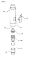
- Figure 1 is a disassembled perspective view illustrating a pencil type cosmetic container according to a preferred embodiment of the present invention
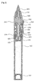
- Figure 2 is a cross sectional view illustrating a pencil type cosmetic container according to a preferred embodiment of the present invention
- Figure 3 is an enlarged view illustrating a pencil type cosmetic container according to a preferred embodiment of the present invention.
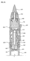
- Figure 4 is a view of an operation state when a user presses upwards a button of a pencil type cosmetic container according to a preferred embodiment of the present invention.
- Figure 5 is a view of an operation state when a button returns to its initial position with the aid of a button recovery spring of a pencil type cosmetic container according to a preferred embodiment of the present invention.
- Figure 1 is a disassembled perspective view illustrating a pencil type cosmetic container according to a preferred embodiment of the present invention
- Figure 2 is a cross sectional view illustrating a pencil type cosmetic container according to a preferred embodiment of the present invention
- Figure 3 is an enlarged view illustrating a pencil type cosmetic container according to a preferred embodiment of the present invention.
- the pencil type cosmetic container comprises a storing container 100, a housing 200, a middle container 300, a seal cap 400, a button 500, a rod part 600, a recovery spring 700 and an applicator 800.
- a piston 110, a pressing rod 420 and a button engaging groove 430 might be further provided.
- the storing container 100 is designed to store various cosmetic stuff such as eye cream, canceller concealer, lip gloss, etc.
- the storing container 100 is made from a synthetic resin material of plastic, with a piston 110 being engaged to a lower part of the storing container 100.
- the piston 110 is pressed by a certain distance depending on the volume of the cosmetics varying as a user uses cosmetic stuff and moves toward the upper side of the storing container 100. So, a user can use cosmetics until all of the remaining cosmetic stuff runs out without a user swaying the storing container upwards and downwards or storing in an opposed side of a discharge part even when a bit amount of cosmetics remains. It is preferred that the piston 110 is made of a smooth material so that an inner space of the storing container 100 can keep a vacuum state.
- the housing 200 is installed at an upper side of the storing container 100, so cosmetic stuff is inputted from the storing container 100 into the interior of the housing.
- the inner diameter of the housing 200 is the same as the outer diameter of the storing container 100, so the housing is inserted from the upper side to the lower side of the storing container 100.
- a stopper 210 is protruded from an outer side of the storing container 100 for thereby limiting the housing 200 from entering into the interior of the storing container 100.
- the stopper 210 is protruded in the same size as the outer diameter of the storing container 100.
- the upper side of the stopper 210 is blocked by means of the middle container 300, which will be described later, and is fixed.
- An inlet hole 220 is formed at a lower side of the housing 200, while passing through the same. Cosmetic stuff is inputted into the interior of the housing 200 with the aid of external pressure. It is preferred that the inlet hole 220 is formed at the center of the housing 200 so that cosmetic stuff can naturally input into the interior.
- a first check valve 230 is installed at a lower side of the housing 200 for thereby closing the inlet hole 220.
- the central portion opens upwards, and cosmetic stuff is inputted via the inlet hole 220.
- the first check valve 230 is made of a certain material which helps transform the first check valve depending on the pressure applied to the cosmetic stuff.
- the middle container 300 is installed at the upper side of the housing 200, with a curved part 310 being formed at a lower side of the middle container for thereby limiting the movement of the stopper 210.
- a button engaging hole 320 passes through the middle container 300 for engaging the button 50 to the seal cap 400 which will be described later.
- the inner diameter of the curved part 310 is the same as the outer diameter of the housing 200 for thereby preventing from escaping from the upper side of the storing container 100 when pressure is applied to the cosmetics.
- a button engaging hole 320 passes through one side of the middle container 300 for helping the button 500 engage with the seal cap 400. It is preferred that the button engaging hole 320 passes through in a vertical direction so that the button 500 can move upwards and downwards.
- the seal cap 400 is engaged with the button 500 and moves in a vertical direction upwards and downwards when an external force from a user is applied, with the center of the seal cap 400 being hollow.
- the upper and lower sides of the seal cap 400 are inserted into the middle container 300 and the housing 200.
- the seal cap 400 moves upwards, the cosmetic stuff positioned in the interior of the storing container 100 moves to the upper side of the seal cap 400 with the aid of atmospheric pressure difference to the outside.
- the center of the seal cap 400 is larger than the diameter of the inlet hole 220 for thereby making the flowing speed of the cosmetic stuff in the seal cap 400 slower, which results in reliably transmitting the cosmetic stuff to the discharge part 610 which will be described later.
- a second check valve 410 is installed at the upper side of the seal cap 400 for thereby opening and closing the central portion of the seal cap 400 with the aid of pressure applied to the cosmetic stuff.
- the center of the second check valve 410 is spaced apart upwards, so cosmetic stuff is inputted via the center of the seal cap 400.
- pressure is applied to the lower side of the second check valve 410, it comes into close contact with the center of the seal cap 400, so the cosmetic stuff is prevented from inputting into the interior of the seal cap 400.
- the second check valve 410 is made of a certain smooth material, so the second check valve 410 can transform depending on the pressure applied to the cosmetic stuff.
- the second check valve 410 had the same operational structure as the first check valve 230.
- a pressing rod 420 might be extended from a lower side of the seal cap 400 for pressing the upper side of the first check valve 230. Since the pressing rod 420 presses the upper side of the first check valve 230, it is possible to prevent the movement of the first check valve 230. Even when external pressure occurs, the pressing rod 420 prevents the movement of the first check valve 230.
- the pressing rod 420 is basically directed to preventing the cosmetic stuff from leaking by means of external pressure.
- the seal cap 400 might be equipped with a button engaging groove 430 at its one side for an easier engagement with the button 500. It is preferred that the button engaging groove 430 is installed at a lower side of the button engaging hole 320 so that the button 500 can move upwards when the button 500 is engaged.
- the button 500 is engaged at one side of the seal cap 400 for thereby moving the seal cap 400 upwards with the aid of a user's external force.
- the button 500 passes through the button engaging hole 320 from the outside of the storing container 100 and is engaged to the seal cap 400. It is preferred that the button 500 is installed at a lower side of the button engaging hole 320 and is movable upwards by means of an external force.
- the rod part 600 is installed at an upper side of the middle container 300, with its central portion being hollow for thereby receiving cosmetic stuff from the lower side and discharging the same upwards.
- a discharge part 610 is upwardly protruded from the center of the rod part 600 for thereby discharging cosmetic stuff toward the discharge part 610, and the discharge part 610 is engaged with an applicator 800 which will be described later.
- the rod part 600 is designed to discharge cosmetic stuff and provides the cosmetic stuff to the user via the applicator 800.
- the recovery spring 700 is installed between the seal cap 400 and the rod part 600 for thereby allowing the seal cap 400 to continue to ascend and descend.
- the lower side of the recovery spring 700 is mounted on the upper side of the seal cap 400, and the upper side of the same is installed at the lower side of the rod part 600.
- the lower side of the applicator 800 is engaged to the discharge part 610. Part of the same is exposed by a certain length, so cosmetic stuff can be put on a user's skin.
- the applicator 800 helps discharge the cosmetic stuff to the outside, which is discharged from the discharge part 610.
- the applicator 800 comprises a brush made of natural hair materials or a silicon tip made of a smooth material. It is preferred that it can feel smooth when touching a user's skin.
- a user holds the cosmetic container.
- the button 500 is pressed upwards using a thumb and moves upwards.
- the seal cap 400 engaged with the button 50 also ascends upwards.
- the seal cap 400 When the seal cap 400 ascends, a pressure difference occurs between the inner and outer sides of the housing 200, so the cosmetic stuff stored in the interior of the storing container 100 ascends into the interior of the housing 200 via the first check valve 230. As the cosmetic stuff stored in the interior of the storing container 100 ascends upwards, the piston 110 moves upwards by a distance corresponding to the volume of the cosmetic stuff which moves upwards. At this time, the recovery spring 700 is positioned in the state pressed by means of the seal cap 400.
- the seal cap 400 vertically descends downwards by means of an elastic recovery force of the recovery spring 700.
- the first check valve 230 is closed, and the second check valve 410 is opened.
- the cosmetic stuff stored in the interior of the housing 200 moves upwards along the center of the seal cap 400.
- the cosmetic stuff which was moved upwards along the center of the seal cap 400 is finally positioned between the seal cap 400 and the rod part 600. So, the cosmetic stuff remains like before the button 500 is pressed. Namely, the user can easily use cosmetic stuff in an easier way by simply pressing the button installed at an outer side.
Landscapes
- Engineering & Computer Science (AREA)
- Mechanical Engineering (AREA)
- Closures For Containers (AREA)
- Containers And Packaging Bodies Having A Special Means To Remove Contents (AREA)
Abstract
Description
- The present invention relates to a pencil type cosmetic container, and in particular to a pencil type cosmetic container which is directed to discharging cosmetic stuff to the outside by pressing upwards a button installed at a side surface of a cosmetic container, which results in an easier use along with a simple construction for thereby decreasing a manufacture cost.
- In addition, it is easier to use since cosmetic stuff can be discharged by pressing upwards a button installed at a side surface of a cosmetic container using one hand.
- A cosmetic container stores eye cream, concealer, lip gloss, eye liner, etc. In particular, a user who needs smooth and fine makeup tends to use a pencil type cosmetic container.
- However, a conventional pencil type cosmetic container is configured so that a user does a makeup directly putting part of cosmetics in a cosmetic container on a pencil, which causes a lot of inconvenience when in use, and a cosmetic container and a pencil are separately stored after use, so they might be lost.
- In addition, a conventional cosmetic container, in which a cosmetics and a pencil are integral, is equipped with a pump at an inner side or is generally used by rotating a front tip of a pencil, both of which cost a lot in the course of manufacture.
- Accordingly, it is an object of the present invention to provide a pencil type cosmetic container which is directed to discharging cosmetic stuff to the outside by pressing upwards a button installed at a side surface of a cosmetic container, which results in an easier use along with a simple construction for thereby decreasing a manufacture cost, while overcoming the problems encountered in a conventional art.
- In the pencil type cosmetic container, it is easier to use since cosmetic stuff can be discharged by pressing upwards a button installed at a side surface of a cosmetic container using one hand.
- To achieve the above objects, there is provided a pencil type cosmetic container which comprises a storing container for storing cosmetic stuff in the interior of the same; a housing which is inserted from an upper side to a lower side of the storing container, with a stopper, which corresponds to the size of an outer diameter of the storing container, being protruded from an outer side of the housing, with a through inlet hole being formed at a lower side of the housing, with a first check valve being installed at an upper side of the inlet hole for opening and closing the inlet hole with the aid of a pressure applied to the cosmetic stuff; a middle container which is engaged to an upper side of the storing container, with a curved part being formed at a lower side of the middle container for limiting the movement of the stopper, with a through button engaging hole being formed at one side of the middle container; a seal cap of which the center is hollow, an upper side is inserted into the interior of the middle container, and a lower side is inserted into the interior of the housing and is movable in a vertical direction, with a second check valve being installed at an upper side of the seal cap for opening and closing the center; a button which passes through the button engaging hole and is engaged to one side of the seal cap; a rod part of which the center is hollow and which is installed at an upper side of the middle container, with a discharge part being protruded upwards; a recovery spring which is installed between the seal cap and the rod part; and an applicator which is inserted into an upper side of the discharge part and absorbs the cosmetic stuff discharged from the rod part.
- There is further provided a piston which is installed at a lower side of the storing container and is contracted as much as the volume of the cosmetic stuff which was used, and moves in an upward direction of the storing container.
- The seal cap further comprises a pressing rod of which one side is extended downwards for thereby pressing an upper side of the first check valve.
- The seal cap further comprises a button engaging groove engaged with the button.
- The center of the seal cap is formed in a passing-through hole shape with above a diameter size of the inlet hole.
- In the present invention, the pencil type cosmetic container is directed to discharging cosmetic stuff to the outside by pressing upwards a button installed at a side surface of a cosmetic container, which results in an easier use along with a simple construction for thereby decreasing a manufacture cost.
- In addition, it is easier to use since cosmetic stuff can be discharged by pressing upwards a button installed at a side surface of a cosmetic container using one hand.
- The present invention will become better understood with reference to the accompanying drawings which are given only by way of illustration and thus are not limitative of the present invention, wherein;
-
Figure 1 is a disassembled perspective view illustrating a pencil type cosmetic container according to a preferred embodiment of the present invention; -
Figure 2 is a cross sectional view illustrating a pencil type cosmetic container according to a preferred embodiment of the present invention; -
Figure 3 is an enlarged view illustrating a pencil type cosmetic container according to a preferred embodiment of the present invention; -
Figure 4 is a view of an operation state when a user presses upwards a button of a pencil type cosmetic container according to a preferred embodiment of the present invention; and -
Figure 5 is a view of an operation state when a button returns to its initial position with the aid of a button recovery spring of a pencil type cosmetic container according to a preferred embodiment of the present invention. - The preferred embodiments of the present invention will be described with reference to the accompanying drawings. The same elements shown in each drawing will be given the same reference numerals.
-
Figure 1 is a disassembled perspective view illustrating a pencil type cosmetic container according to a preferred embodiment of the present invention, andFigure 2 is a cross sectional view illustrating a pencil type cosmetic container according to a preferred embodiment of the present invention, andFigure 3 is an enlarged view illustrating a pencil type cosmetic container according to a preferred embodiment of the present invention. - As shown in
Figures 1 to 3 , the pencil type cosmetic container according to the present invention comprises astoring container 100, ahousing 200, amiddle container 300, aseal cap 400, abutton 500, arod part 600, arecovery spring 700 and anapplicator 800. Apiston 110, apressing rod 420 and abutton engaging groove 430 might be further provided. - The storing
container 100 is designed to store various cosmetic stuff such as eye cream, canceller concealer, lip gloss, etc. The storingcontainer 100 is made from a synthetic resin material of plastic, with apiston 110 being engaged to a lower part of the storingcontainer 100. - The
piston 110 is pressed by a certain distance depending on the volume of the cosmetics varying as a user uses cosmetic stuff and moves toward the upper side of the storingcontainer 100. So, a user can use cosmetics until all of the remaining cosmetic stuff runs out without a user swaying the storing container upwards and downwards or storing in an opposed side of a discharge part even when a bit amount of cosmetics remains. It is preferred that thepiston 110 is made of a smooth material so that an inner space of the storingcontainer 100 can keep a vacuum state. - The
housing 200 is installed at an upper side of thestoring container 100, so cosmetic stuff is inputted from the storingcontainer 100 into the interior of the housing. The inner diameter of thehousing 200 is the same as the outer diameter of thestoring container 100, so the housing is inserted from the upper side to the lower side of thestoring container 100. At this time, astopper 210 is protruded from an outer side of the storingcontainer 100 for thereby limiting thehousing 200 from entering into the interior of the storingcontainer 100. - It is preferred that the
stopper 210 is protruded in the same size as the outer diameter of thestoring container 100. The upper side of thestopper 210 is blocked by means of themiddle container 300, which will be described later, and is fixed. - An
inlet hole 220 is formed at a lower side of thehousing 200, while passing through the same. Cosmetic stuff is inputted into the interior of thehousing 200 with the aid of external pressure. It is preferred that theinlet hole 220 is formed at the center of thehousing 200 so that cosmetic stuff can naturally input into the interior. - A
first check valve 230 is installed at a lower side of thehousing 200 for thereby closing theinlet hole 220. As shown inFigure 4 , when pressure is applied to the upper side of thefirst check valve 230, the central portion opens upwards, and cosmetic stuff is inputted via theinlet hole 220. As shown inFigure 5 , when pressure is applied to the lower side of thefirst check valve 230, it comes into close contact with theinlet hole 220, so the cosmetic stuff is prevented from inputting into the interior of thehousing 200. It is preferred that thefirst check valve 230 is made of a certain material which helps transform the first check valve depending on the pressure applied to the cosmetic stuff. - The
middle container 300 is installed at the upper side of thehousing 200, with acurved part 310 being formed at a lower side of the middle container for thereby limiting the movement of thestopper 210. Abutton engaging hole 320 passes through themiddle container 300 for engaging the button 50 to theseal cap 400 which will be described later. - The inner diameter of the
curved part 310 is the same as the outer diameter of thehousing 200 for thereby preventing from escaping from the upper side of the storingcontainer 100 when pressure is applied to the cosmetics. - A
button engaging hole 320 passes through one side of themiddle container 300 for helping thebutton 500 engage with theseal cap 400. It is preferred that thebutton engaging hole 320 passes through in a vertical direction so that thebutton 500 can move upwards and downwards. - The
seal cap 400 is engaged with thebutton 500 and moves in a vertical direction upwards and downwards when an external force from a user is applied, with the center of theseal cap 400 being hollow. The upper and lower sides of theseal cap 400 are inserted into themiddle container 300 and thehousing 200. When theseal cap 400 moves upwards, the cosmetic stuff positioned in the interior of the storingcontainer 100 moves to the upper side of theseal cap 400 with the aid of atmospheric pressure difference to the outside. At this time, it is preferred that the center of theseal cap 400 is larger than the diameter of theinlet hole 220 for thereby making the flowing speed of the cosmetic stuff in theseal cap 400 slower, which results in reliably transmitting the cosmetic stuff to thedischarge part 610 which will be described later. - A
second check valve 410 is installed at the upper side of theseal cap 400 for thereby opening and closing the central portion of theseal cap 400 with the aid of pressure applied to the cosmetic stuff. When pressure is applied to the upper side, the center of thesecond check valve 410 is spaced apart upwards, so cosmetic stuff is inputted via the center of theseal cap 400. When pressure is applied to the lower side of thesecond check valve 410, it comes into close contact with the center of theseal cap 400, so the cosmetic stuff is prevented from inputting into the interior of theseal cap 400. It is preferred that thesecond check valve 410 is made of a certain smooth material, so thesecond check valve 410 can transform depending on the pressure applied to the cosmetic stuff. Thesecond check valve 410 had the same operational structure as thefirst check valve 230. - A
pressing rod 420 might be extended from a lower side of theseal cap 400 for pressing the upper side of thefirst check valve 230. Since thepressing rod 420 presses the upper side of thefirst check valve 230, it is possible to prevent the movement of thefirst check valve 230. Even when external pressure occurs, thepressing rod 420 prevents the movement of thefirst check valve 230. Thepressing rod 420 is basically directed to preventing the cosmetic stuff from leaking by means of external pressure. - In addition, the
seal cap 400 might be equipped with abutton engaging groove 430 at its one side for an easier engagement with thebutton 500. It is preferred that thebutton engaging groove 430 is installed at a lower side of thebutton engaging hole 320 so that thebutton 500 can move upwards when thebutton 500 is engaged. - The
button 500 is engaged at one side of theseal cap 400 for thereby moving theseal cap 400 upwards with the aid of a user's external force. Thebutton 500 passes through thebutton engaging hole 320 from the outside of the storingcontainer 100 and is engaged to theseal cap 400. It is preferred that thebutton 500 is installed at a lower side of thebutton engaging hole 320 and is movable upwards by means of an external force. - The
rod part 600 is installed at an upper side of themiddle container 300, with its central portion being hollow for thereby receiving cosmetic stuff from the lower side and discharging the same upwards. Adischarge part 610 is upwardly protruded from the center of therod part 600 for thereby discharging cosmetic stuff toward thedischarge part 610, and thedischarge part 610 is engaged with anapplicator 800 which will be described later. Therod part 600 is designed to discharge cosmetic stuff and provides the cosmetic stuff to the user via theapplicator 800. - The
recovery spring 700 is installed between theseal cap 400 and therod part 600 for thereby allowing theseal cap 400 to continue to ascend and descend. The lower side of therecovery spring 700 is mounted on the upper side of theseal cap 400, and the upper side of the same is installed at the lower side of therod part 600. When a user presses the upper side of thebutton 500, theseal cap 400 vertically ascends at the same time. At this time, theseal cap 400 vertically descends downwards with the aid of the elastic recovery force of therecovery spring 700. Namely, therecovery spring 700 allows theseal cap 400 to continuously ascend and descend by using an elastic recovery force. - The lower side of the
applicator 800 is engaged to thedischarge part 610. Part of the same is exposed by a certain length, so cosmetic stuff can be put on a user's skin. Theapplicator 800 helps discharge the cosmetic stuff to the outside, which is discharged from thedischarge part 610. Theapplicator 800 comprises a brush made of natural hair materials or a silicon tip made of a smooth material. It is preferred that it can feel smooth when touching a user's skin. - The operation procedures of a side-processed type cosmetic container according to a preferred embodiment of the present invention will be described with reference to
Figures 4 and5 . - As shown in
Figure 4 , a user holds the cosmetic container. Thebutton 500 is pressed upwards using a thumb and moves upwards. At this time, as thebutton 500 ascends, theseal cap 400 engaged with the button 50 also ascends upwards. - When the
seal cap 400 moves upwards, the space between theseal cap 400 and therod part 600 decreases. At this time, since thesecond check valve 410 blocks the center of theseal cap 400, the cosmetic stuff stored between theseal cap 400 and therod part 600 is discharged upwards via thedischarge part 610. So, the user can use cosmetic stuff by simply pressing thebutton 500 upwards, which is one of the key features of the present invention. - When the
seal cap 400 ascends, a pressure difference occurs between the inner and outer sides of thehousing 200, so the cosmetic stuff stored in the interior of the storingcontainer 100 ascends into the interior of thehousing 200 via thefirst check valve 230. As the cosmetic stuff stored in the interior of the storingcontainer 100 ascends upwards, thepiston 110 moves upwards by a distance corresponding to the volume of the cosmetic stuff which moves upwards. At this time, therecovery spring 700 is positioned in the state pressed by means of theseal cap 400. - As shown in
Figure 5 , when a user separates a thumb from thebutton 500, theseal cap 400 vertically descends downwards by means of an elastic recovery force of therecovery spring 700. As theseal cap 700 descends, thefirst check valve 230 is closed, and thesecond check valve 410 is opened. The cosmetic stuff stored in the interior of thehousing 200 moves upwards along the center of theseal cap 400. The cosmetic stuff which was moved upwards along the center of theseal cap 400 is finally positioned between theseal cap 400 and therod part 600. So, the cosmetic stuff remains like before thebutton 500 is pressed. Namely, the user can easily use cosmetic stuff in an easier way by simply pressing the button installed at an outer side. - As the present invention may be embodied in several forms without departing from the spirit or essential characteristics thereof, it should also be understood that the above-described examples are not limited by any of the details of the foregoing description, unless otherwise specified, but rather should be construed broadly within its spirit and scope as defined in the appended claims, and therefore all changes and modifications that fall within the meets and bounds of the claims, or equivalences of such meets and bounds are therefore intended to be embraced by the appended claims.
Claims (5)
- A pencil type cosmetic container, comprising:a storing container for storing cosmetic stuff in the interior of the same;a housing which is inserted from an upper side to a lower side of the storing container, with a stopper, which corresponds to the size of an outer diameter of the storing container, being protruded from an outer side of the housing, with a through inlet hole being formed at a lower side of the housing, with a first check valve being installed at an upper side of the inlet hole for opening and closing the inlet hole with the aid of a pressure applied to the cosmetic stuff;a middle container which is engaged to an upper side of the storing container, with a curved part being formed at a lower side of the middle container for limiting the movement of the stopper, with a through button engaging hole being formed at one side of the middle container;a seal cap of which the center is hollow, an upper side is inserted into the interior of the middle container, and a lower side is inserted into the interior of the housing and is movable in a vertical direction, with a second check valve being installed at an upper side of the seal cap for opening and closing the center;a button which passes through the button engaging hole and is engaged to one side of the seal cap;a rod part of which the center is hollow and which is installed at an upper side of the middle container, with a discharge part being protruded upwards;a recovery spring which is installed between the seal cap and the rod part; andan applicator which is inserted into an upper side of the discharge part and absorbs the cosmetic stuff discharged from the rod part.
- A pencil type cosmetic container according to claim 1, further comprising:a piston which is installed at a lower side of the storing container and is contracted as much as the volume of the cosmetic stuff which was used, and moves in an upward direction of the storing container.
- A pencil type cosmetic container according to claim 1, wherein said seal cap further comprises:a pressing rod of which one side is extended downwards for thereby pressing an upper side of the first check valve.
- A pencil type cosmetic container according to claim 1, wherein said seal cap further comprises a button engaging groove engaged with the button.
- A pencil type cosmetic container according to claim 1, wherein the center of the seal cap is formed in a passing-through hole shape with above a diameter size of the inlet hole.
Applications Claiming Priority (2)
| Application Number | Priority Date | Filing Date | Title |
|---|---|---|---|
| KR2020080011398U KR200450995Y1 (en) | 2008-08-26 | 2008-08-26 | Pencil type cosmetic container |
| PCT/KR2009/004711 WO2010024568A1 (en) | 2008-08-26 | 2009-08-24 | Pencil-shaped cosmetic container |
Publications (2)
| Publication Number | Publication Date |
|---|---|
| EP2356920A1 true EP2356920A1 (en) | 2011-08-17 |
| EP2356920A4 EP2356920A4 (en) | 2012-04-25 |
Family
ID=41721664
Family Applications (1)
| Application Number | Title | Priority Date | Filing Date |
|---|---|---|---|
| EP09810173A Withdrawn EP2356920A4 (en) | 2008-08-26 | 2009-08-24 | Pencil-shaped cosmetic container |
Country Status (6)
| Country | Link |
|---|---|
| US (1) | US8308386B2 (en) |
| EP (1) | EP2356920A4 (en) |
| JP (1) | JP2012501204A (en) |
| KR (1) | KR200450995Y1 (en) |
| CN (1) | CN102131421A (en) |
| WO (1) | WO2010024568A1 (en) |
Families Citing this family (17)
| Publication number | Priority date | Publication date | Assignee | Title |
|---|---|---|---|---|
| KR200456236Y1 (en) * | 2008-12-16 | 2011-10-20 | 주식회사 하나 | A standard capacity discharge case of liquid content |
| US9770736B2 (en) * | 2013-07-09 | 2017-09-26 | Gerhard Brugger | Metering dispenser for discharging an in particular pasty or viscous material, such as cosmetic cream, adhesive, and the like |
| GB2526886B (en) * | 2014-07-01 | 2016-05-11 | Easy-Do Products Ltd | Improvements to fluid-dispensing apparatus |
| KR200479431Y1 (en) * | 2014-12-16 | 2016-01-27 | 강성일 | An applicator for discharging gel type contents having a pressure button |
| US10206484B2 (en) * | 2016-03-16 | 2019-02-19 | HCT Group Holdings Limited | Airless cosmetics dispenser |
| KR101682855B1 (en) | 2016-04-18 | 2016-12-05 | 김진우 | Airtight type pencil cosmetic case |
| JP6612839B2 (en) * | 2017-03-10 | 2019-11-27 | テヤン レナー カンパニー、リミテッド | Cosmetic container |
| KR101912114B1 (en) * | 2017-08-28 | 2018-10-29 | (주)아모레퍼시픽 | cosmetic tool |
| KR101971920B1 (en) * | 2017-08-31 | 2019-04-24 | (주)아모레퍼시픽 | Cosmetic container being able to use two kind of cosmetics |
| JP6956588B2 (en) * | 2017-10-25 | 2021-11-02 | 佐藤製薬株式会社 | Coating stopper |
| KR101987650B1 (en) * | 2017-10-31 | 2019-06-12 | 주식회사 코스메카코리아 | Cosmetic case for two-type cosmetics |
| KR102015622B1 (en) * | 2018-02-05 | 2019-08-28 | (주)연우 | fluid vessel |
| CN113347904B (en) * | 2020-05-25 | 2022-04-26 | 韩国科玛株式会社 | Contents container |
| JP2022134868A (en) * | 2021-03-04 | 2022-09-15 | ロレアル | Applicator with foaming body introduced |
| CN112957604B (en) * | 2021-03-29 | 2022-07-05 | 聊城市人民医院 | A self-priming wax supplementing positive pressure bone crayon |
| US11910904B2 (en) * | 2022-01-21 | 2024-02-27 | Elc Management Llc | Pen applicator system for applying a cosmetic product |
| CN117652766A (en) * | 2022-08-26 | 2024-03-08 | 洽兴包装工业(中国)有限公司 | Side push makeup pen |
Family Cites Families (25)
| Publication number | Priority date | Publication date | Assignee | Title |
|---|---|---|---|---|
| US2987743A (en) * | 1958-04-28 | 1961-06-13 | Richard D Martin | Toothbrush |
| EP0123518B1 (en) * | 1983-04-20 | 1987-11-25 | Sasuke Endo | Toothbrush |
| US4692047A (en) * | 1983-04-20 | 1987-09-08 | Sasuke Endo | Brush for applying material in liquid or emulsion form |
| US4624413A (en) * | 1985-01-23 | 1986-11-25 | Corsette Douglas Frank | Trigger type sprayer |
| DE3641390C1 (en) * | 1986-12-04 | 1988-02-11 | Schwan Stabilo Schwanhaeusser | Application device |
| US4963046A (en) * | 1987-05-13 | 1990-10-16 | Kao Corporation | Toothbrush |
| US4991749A (en) * | 1988-05-17 | 1991-02-12 | Photofinish Cosmetics, Inc. | Manually-operated fluid dispenser and associated closure cap |
| FR2660878B1 (en) * | 1990-04-12 | 1993-06-18 | Lvmh Rech | DEVICE FOR SEALING ANY APPLICATOR APPARATUS OF ANY LIQUID PRODUCT AND APPLICATOR APPARATUS FOR USE WITH SUCH DEVICE. |
| JPH11206453A (en) * | 1998-01-20 | 1999-08-03 | Ikeda Bussan Kk | Side knock type container |
| KR200238108Y1 (en) | 1998-09-11 | 2001-11-22 | 강성일 | A liquid type lipstick dispenser |
| US6200055B1 (en) * | 1999-06-18 | 2001-03-13 | Stephen Gould Corporation | Dispenser device for dispensing metered doses of viscous material |
| GB2363977B (en) * | 2000-06-20 | 2003-07-02 | London Oil Refining Company Lt | A toilet cleaning apparatus |
| KR200230104Y1 (en) | 2000-12-06 | 2001-07-03 | 강성일 | Gel-Form Lipstick Dispenser |
| JP2002262932A (en) * | 2001-03-09 | 2002-09-17 | Shiseido Co Ltd | One drop container |
| KR20030078221A (en) * | 2002-03-28 | 2003-10-08 | 박설 | Paste contained toothbrush |
| KR200338799Y1 (en) * | 2003-09-08 | 2004-01-24 | 변영광 | Make-up apparatus for cosmetics of liquid type |
| US7427004B2 (en) * | 2003-10-20 | 2008-09-23 | Meadwestvaco Calmar, Inc. | Hand held pressurized sprayer |
| JP4468002B2 (en) * | 2004-02-02 | 2010-05-26 | 壽印刷紙工株式会社 | Side knock type feeding mechanism |
| KR100553830B1 (en) * | 2004-08-16 | 2006-02-22 | 장양설 | Device for tooth brush |
| BRPI0516150A (en) * | 2004-09-27 | 2008-08-26 | Medical Instill Tech Inc | dispenser to release a substance |
| KR200408260Y1 (en) * | 2005-11-30 | 2006-02-07 | 강성일 | A standard capacity discharge case of liquid content |
| KR200417200Y1 (en) | 2006-02-28 | 2006-05-24 | (주)연우 | dispenser |
| KR200439672Y1 (en) * | 2006-12-15 | 2008-04-25 | 강성일 | Dispensing Tip Replaceable Content Dispensing Container |
| KR100938440B1 (en) * | 2007-12-06 | 2010-01-25 | 주식회사 태성산업 | Cosmetic Container |
| KR200456236Y1 (en) * | 2008-12-16 | 2011-10-20 | 주식회사 하나 | A standard capacity discharge case of liquid content |
-
2008
- 2008-08-26 KR KR2020080011398U patent/KR200450995Y1/en not_active Expired - Fee Related
-
2009
- 2009-08-24 CN CN2009801332942A patent/CN102131421A/en active Pending
- 2009-08-24 US US13/060,472 patent/US8308386B2/en not_active Expired - Fee Related
- 2009-08-24 WO PCT/KR2009/004711 patent/WO2010024568A1/en not_active Ceased
- 2009-08-24 EP EP09810173A patent/EP2356920A4/en not_active Withdrawn
- 2009-08-24 JP JP2011524894A patent/JP2012501204A/en not_active Ceased
Also Published As
| Publication number | Publication date |
|---|---|
| US20110158737A1 (en) | 2011-06-30 |
| KR200450995Y1 (en) | 2010-11-16 |
| CN102131421A (en) | 2011-07-20 |
| JP2012501204A (en) | 2012-01-19 |
| US8308386B2 (en) | 2012-11-13 |
| WO2010024568A1 (en) | 2010-03-04 |
| EP2356920A4 (en) | 2012-04-25 |
| KR20100002400U (en) | 2010-03-08 |
Similar Documents
| Publication | Publication Date | Title |
|---|---|---|
| US8308386B2 (en) | Pencil-shaped cosmetic container | |
| US8608029B2 (en) | Cosmetic container for mixing and using heterogeneous contents | |
| JP6909723B2 (en) | Powder discharge container | |
| US7377296B2 (en) | Device for packaging and dispensing a cosmetic or another care product | |
| KR101631827B1 (en) | Pump type Compact case | |
| EP2995571A1 (en) | Pumping-type cosmetic container comprising side button | |
| JP6886941B2 (en) | Liquid discharge container | |
| US20230117210A1 (en) | Cosmetic case having refill structure | |
| EP3420843A1 (en) | Pump-type cosmetic container having side button | |
| US20170354232A1 (en) | Pumping type of cosmetic container equipped with side button | |
| JP2020512152A (en) | Cosmetic container for different cosmetics | |
| KR101048412B1 (en) | Cosmetic container | |
| US7878374B2 (en) | Fluid product dispenser | |
| KR101151002B1 (en) | case for cosmetic | |
| KR101071101B1 (en) | The cosmetic case | |
| KR102604248B1 (en) | Cosmetic container with replacement structure of refill container | |
| EP3811814A1 (en) | Powder-discharging container | |
| KR102795074B1 (en) | Cosmetic container having airless pump and cap for the cosmetic container | |
| KR20170138094A (en) | Cosmetic case | |
| KR102604247B1 (en) | Cosmetic container with replacement structure of refill container | |
| KR101673396B1 (en) | Container having a changeable body frame | |
| JP2004276974A (en) | Dispenser container |
Legal Events
| Date | Code | Title | Description |
|---|---|---|---|
| PUAI | Public reference made under article 153(3) epc to a published international application that has entered the european phase |
Free format text: ORIGINAL CODE: 0009012 |
|
| 17P | Request for examination filed |
Effective date: 20110324 |
|
| AK | Designated contracting states |
Kind code of ref document: A1 Designated state(s): AT BE BG CH CY CZ DE DK EE ES FI FR GB GR HR HU IE IS IT LI LT LU LV MC MK MT NL NO PL PT RO SE SI SK SM TR |
|
| DAX | Request for extension of the european patent (deleted) | ||
| A4 | Supplementary search report drawn up and despatched |
Effective date: 20120322 |
|
| RIC1 | Information provided on ipc code assigned before grant |
Ipc: A45D 34/04 20060101AFI20120316BHEP |
|
| 17Q | First examination report despatched |
Effective date: 20130409 |
|
| GRAP | Despatch of communication of intention to grant a patent |
Free format text: ORIGINAL CODE: EPIDOSNIGR1 |
|
| INTG | Intention to grant announced |
Effective date: 20131114 |
|
| STAA | Information on the status of an ep patent application or granted ep patent |
Free format text: STATUS: THE APPLICATION IS DEEMED TO BE WITHDRAWN |
|
| 18D | Application deemed to be withdrawn |
Effective date: 20140325 |