EP2356753B1 - Link data transmission method, node and system - Google Patents
Link data transmission method, node and system Download PDFInfo
- Publication number
- EP2356753B1 EP2356753B1 EP09829470.5A EP09829470A EP2356753B1 EP 2356753 B1 EP2356753 B1 EP 2356753B1 EP 09829470 A EP09829470 A EP 09829470A EP 2356753 B1 EP2356753 B1 EP 2356753B1
- Authority
- EP
- European Patent Office
- Prior art keywords
- node
- data
- transmitted
- sending
- current
- Prior art date
- Legal status (The legal status is an assumption and is not a legal conclusion. Google has not performed a legal analysis and makes no representation as to the accuracy of the status listed.)
- Active
Links
- 230000005540 biological transmission Effects 0.000 title claims description 71
- 238000000034 method Methods 0.000 title claims description 31
- 230000007246 mechanism Effects 0.000 description 11
- 238000010586 diagram Methods 0.000 description 7
- 230000008569 process Effects 0.000 description 6
- 238000005516 engineering process Methods 0.000 description 5
- 230000008859 change Effects 0.000 description 3
- 230000006870 function Effects 0.000 description 3
- 238000012986 modification Methods 0.000 description 3
- 230000004048 modification Effects 0.000 description 3
- 238000012545 processing Methods 0.000 description 3
- 230000004075 alteration Effects 0.000 description 2
- 238000004590 computer program Methods 0.000 description 2
- 230000003287 optical effect Effects 0.000 description 2
- 230000008901 benefit Effects 0.000 description 1
- 238000004891 communication Methods 0.000 description 1
- 238000011161 development Methods 0.000 description 1
- 238000005457 optimization Methods 0.000 description 1
- 238000011084 recovery Methods 0.000 description 1
- 239000004557 technical material Substances 0.000 description 1
Images
Classifications
-
- H—ELECTRICITY
- H04—ELECTRIC COMMUNICATION TECHNIQUE
- H04L—TRANSMISSION OF DIGITAL INFORMATION, e.g. TELEGRAPHIC COMMUNICATION
- H04L41/00—Arrangements for maintenance, administration or management of data switching networks, e.g. of packet switching networks
- H04L41/12—Discovery or management of network topologies
-
- H—ELECTRICITY
- H04—ELECTRIC COMMUNICATION TECHNIQUE
- H04L—TRANSMISSION OF DIGITAL INFORMATION, e.g. TELEGRAPHIC COMMUNICATION
- H04L12/00—Data switching networks
- H04L12/02—Details
- H04L12/16—Arrangements for providing special services to substations
- H04L12/18—Arrangements for providing special services to substations for broadcast or conference, e.g. multicast
- H04L12/1854—Arrangements for providing special services to substations for broadcast or conference, e.g. multicast with non-centralised forwarding system, e.g. chaincast
-
- H—ELECTRICITY
- H04—ELECTRIC COMMUNICATION TECHNIQUE
- H04L—TRANSMISSION OF DIGITAL INFORMATION, e.g. TELEGRAPHIC COMMUNICATION
- H04L45/00—Routing or path finding of packets in data switching networks
- H04L45/48—Routing tree calculation
-
- H—ELECTRICITY
- H04—ELECTRIC COMMUNICATION TECHNIQUE
- H04L—TRANSMISSION OF DIGITAL INFORMATION, e.g. TELEGRAPHIC COMMUNICATION
- H04L67/00—Network arrangements or protocols for supporting network services or applications
- H04L67/01—Protocols
- H04L67/10—Protocols in which an application is distributed across nodes in the network
- H04L67/104—Peer-to-peer [P2P] networks
- H04L67/1044—Group management mechanisms
- H04L67/1053—Group management mechanisms with pre-configuration of logical or physical connections with a determined number of other peers
-
- H—ELECTRICITY
- H04—ELECTRIC COMMUNICATION TECHNIQUE
- H04L—TRANSMISSION OF DIGITAL INFORMATION, e.g. TELEGRAPHIC COMMUNICATION
- H04L67/00—Network arrangements or protocols for supporting network services or applications
- H04L67/01—Protocols
- H04L67/10—Protocols in which an application is distributed across nodes in the network
- H04L67/104—Peer-to-peer [P2P] networks
- H04L67/1087—Peer-to-peer [P2P] networks using cross-functional networking aspects
- H04L67/1089—Hierarchical topologies
Definitions
- the present invention relates to the field of data transmission technology, and in particular to a method, node and system for link data transmission.
- a link copy (LCP) technique is provided herein.
- LCP link copy
- the system includes a data source node and at least one data destination node.
- a tree connection is established between the data source node and the data destination node.
- the data destination node is a child node of the data source node.
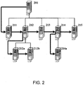
- Fig. 2 is a schematic diagram of another system for link data transmission in accordance with some embodiments.
- the system of Fig. 2 differs from that of Fig. 1 in that the system shown in Fig. 2 includes a three-level tree structure.
- the source node 201 is a parent node in the tree structure and each of the destination nodes 211-215 is a child node of node 201.
- Nodes 211-215 are sibling nodes of one another.
- Each of the nodes 212a and 212b is a child node of the node 212.
- Nodes 212a and 212b are sibling nodes of each other.
- Node 214a is a child node of node 214.
- the current node continues to send the data to two nodes. If the two nodes meeting the above conditions cannot be found, no data is sent correspondingly. According to such a transmission mechanism, after being sent out from the source node, data may be sent to all the destination nodes in a traversed way, and no repeated data transmission will occur between the destination nodes.
- node 201 may delete the information of node 211 from its child node list.
- node 212 becomes the first child node that registers with node 201.
- node 201 may delete the information of node 212 from its child node list and inform such status to node 211 that registers prior to node 212.
- node 213 becomes the succeeding sibling node of node 211.
- data is transmitted between computers in the form of files. Transmission of each file is handled by a separate thread, which is termed as FileTask.
- a FileTask is divided into four phases: OpenFile (starting transmission of file), Blocks (transmitting contents of file), EndFile (ending transmission of file) and RecovFile (recovering lost blocks).
- OpenFile starting transmission of file
- Blocks transmitting contents of file
- EndFile ending transmission of file
- RecovFile recovery lost blocks.
- a file is transmitted in the form of file blocks. The receiver node performs a check when receiving a file block. If a data error occurs, recovery of the erroneous data blocks may be requested separately during the RecovFile phase, and there is no need to retransmit the whole file.
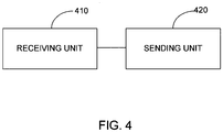
- an example node includes a receiving unit 410 configured to obtain data to be transmitted.
- the receiving unit 410 is configured to obtain original data to be transmitted, and for a destination node, the receiving unit 410 is configured to receive the data to be transmitted that is sent from another node.
Description
- The present invention relates to the field of data transmission technology, and in particular to a method, node and system for link data transmission.
- With the development of the Internet technologies, two devices in a network can share resources through data transmission. In certain applications, data may need to be copied from a source device to multiple destination devices. In a commonly used method, a source device where the source data is located copies the source data to a plurality of destination devices one by one. Such a method is inconvenient to implement, and may also occupy the bandwidth between a source device and a destination device during a copy operation between the two. Particularly in situations where the destination devices and the source device are located in different network sections and the destination devices are located in the same network section, such a copy method apparently wastes valuable inter-network bandwidth resources between different network sections.
- Presently, the peer-to-peer (P2P) or node-to-node technology is a popular data transmission technique. In P2P, at the same time of receiving data a device may also transmit the received data to other devices. The bandwidth available between the destination devices that are otherwise idle can thus be used. When P2P is employed in the above scenario, the intra-network bandwidth available between the destination devices can be used effectively, potentially reducing the amount of data transmission on the inter-network bandwidth between different network sections and saving the inter-network bandwidth resources.Document D: MARC SCHIELY ET AL: "Peer-to-Peer Distribution Architectures Providing Uniform Download Rates", 1 January 2005 (2005-01-01), ON THE MOVE TO MEANINGFUL INTERNET SYSTEMS 2005: COOPIS, DOA, AND ODBA SE LECTURE NOTES IN COMPUTER SCIENCE;;LNCS, SPRINGER, BERLIN, DE, PAGE(S) 1083 - 1096,ISBN: 978-3-540-29738-3 discloses methods to send data between nodes in a P2P fashion in order to take advantage of bandwidth otherwise unused.
- A number of issues remain in existing P2P technology. In the currently P2P applications, each device typically can only control sending from and receiving data to itself (e.g., controlling the sending rate and the receiving rate, and the number of destination devices, etc.), and a unitary control for data transmission of an entire network typically cannot be achieved at a single device using the transmission mechanism of P2P. When the amount of data transmission is too large, it may overwhelm and paralyze the network.
- In the above-described application scenario where a source device needs to copy data to multiple destination devices and the data transmission is initiated by the source device, when a change occurs in the amount of the data transmission and/or the number of the destination devices, the current P2P technology typically cannot implement a unitary control on a single source device (or on a certain destination device) for the data transmission of the whole network, since the destination devices may only receive data passively.
- According to one aspect of the invention there is provided a method for link data transmission to a plurality of nodes, comprising: establishing a tree connection among the plurality of nodes; receiving data to be transmitted at a current node; in the event that the current node receiving the data to be transmitted has at least one child node, sending by the current node the data to be transmitted to one of the at least one child node; and in the event that the current node receiving the data to be transmitted has at least one sibling node that has not obtained the data to be transmitted, sending by the current node the data to be transmitted to one of the at least one sibling node; wherein sending by the current node the data to be transmitted to one of the at least one child node comprises sending the data to be transmitted to a first child node that establishes a connection with the current node; and sending the data to be transmitted to one of the at least one sibling node comprises sending the data to be transmitted to a node that is the first node, subsequent to the current node, to establish a connection with a parent node of the current node.
- A corresponding link data transmission node and a system for link data transmission are also provided.
- Various embodiments of the invention are disclosed in the following detailed description and the accompanying drawings.
-
Fig. 1 is a schematic diagram of a system for link data transmission in accordance with some embodiments. -
Fig. 2 is a schematic diagram of another system for link data transmission in accordance with some embodiments. -
Fig. 3 is a flowchart of implementing a method in accordance with some embodiments. -
Fig. 4 is a schematic diagram of a node for link data transmission in accordance with some embodiments. -
Fig. 5 is a schematic diagram of another node for link data transmission in accordance with some embodiments. -
Fig. 6 is a schematic diagram of still another node for link data transmission in accordance with some embodiments. - The invention can be implemented in numerous ways, including as a process; an apparatus; a system; a composition of matter; a computer program product embodied on a computer readable storage medium; and/or a processor, such as a processor configured to execute instructions stored on and/or provided by a memory coupled to the processor. In this specification, these implementations, or any other form that the invention may take, may be referred to as techniques. In general, the order of the steps of disclosed processes may be altered within the scope of the invention. Unless stated otherwise, a component such as a processor or a memory described as being configured to perform a task may be implemented as a general component that is temporarily configured to perform the task at a given time or a specific component that is manufactured to perform the task. As used herein, the term 'processor' refers to one or more devices, circuits, and/or processing cores configured to process data, such as computer program instructions.
- A detailed description of one or more embodiments of the invention is provided below along with accompanying figures that illustrate the principles of the invention. The invention is described in connection with such embodiments, but the invention is not limited to any embodiment. The scope of the invention is limited only by the claims and the invention encompasses numerous alternatives, modifications and equivalents. Numerous specific details are set forth in the following description in order to provide a thorough understanding of the invention. These details are provided for the purpose of example and the invention may be practiced according to the claims without some or all of these specific details. For the purpose of clarity, technical material that is known in the technical fields related to the invention has not been described in detail so that the invention is not unnecessarily obscured.
- A link copy (LCP) technique is provided herein. First, a system for link data transmission in accordance with some embodiments is provided herein. In some embodiments, the system includes a data source node and at least one data destination node. A tree connection is established between the data source node and the data destination node. The data destination node is a child node of the data source node.
-
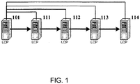
Fig. 1 is a schematic diagram of a system for link data transmission in accordance with some embodiments. In this example, 101 denotes a data source node, 111-114 denote data destination nodes, and the lines between the nodes denote connections established between the nodes. As used here, a node refers to a computing device capable of transmitting and receiving data. It can be seen that the system is of a two-level tree structure, thesource node 101 is a parent node in the tree structure and each of the destination nodes 111-114 is a child node of thenode 101. The nodes 111-114 have thesame parent node 101 and are thus sibling nodes of one another. - In
Fig. 1 , the arrows between the nodes indicate the data transmission occurring in the system. It can be seen that thedata source node 101 sends data to a child node (denoted by 111 inFig. 1 ) of itself; upon receiving the data, one of the data destination nodes 111-114 sends the received data to a sibling node of itself. To avoid repeated data transmission, the sibling node should be selected as a node that has not obtained the data to be transmitted. The data transmission path indicated in the figure is 111→112→113→114. When thenode 114 receives the data, all the sibling nodes of it have already received the data to be transmitted. Therefore, thenode 114 does not send data to another node and the data transmission is terminated. -
Fig. 2 is a schematic diagram of another system for link data transmission in accordance with some embodiments. The system ofFig. 2 differs from that ofFig. 1 in that the system shown inFig. 2 includes a three-level tree structure. Thesource node 201 is a parent node in the tree structure and each of the destination nodes 211-215 is a child node ofnode 201. Nodes 211-215 are sibling nodes of one another. Each of thenodes node 212. Nodes 212a and 212b are sibling nodes of each other. Node 214a is a child node ofnode 214. - From the arrows in
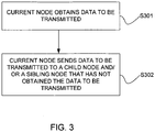
Fig. 2 , it can be seen that a destination node with a child node may send the received data to a child node in addition to a sibling node. For example,node 212 sends the data to 213 of its sibling nodes and 212a of its child nodes, andnode 214 sends the data to 215 of its sibling nodes and 214a of its child nodes. - A data transmission mechanism implemented by each node in a link data transmission system in accordance with some embodiments may be summarized as a flow shown in
Fig. 3 , which includes the following steps. - S301, a current node obtains data to be transmitted. If the current node is a data source node, the obtained data is the original data to be transmitted. If the current node is a data destination node, it receives the data to be transmitted that is sent from another node.
- S302, the current node sends the data to be transmitted to one of its child nodes, and one of its sibling nodes that has not obtained the data to be transmitted.
- Therefore, after receiving data, the current node continues to send the data to two nodes. If the two nodes meeting the above conditions cannot be found, no data is sent correspondingly. According to such a transmission mechanism, after being sent out from the source node, data may be sent to all the destination nodes in a traversed way, and no repeated data transmission will occur between the destination nodes.
- It is to be noted that although a two-level and a three-level structure having been mentioned with respect to Embodiments 1 and 2 described above, it readily occurs to those skilled in the art that other forms of systems with a tree structure employing the data transmission mechanism provided herein fall into the scope of the present invention.
- To establish a tree connection, in some embodiments the destination nodes in the same network or subnet is connected with a parent node. In
Fig. 2 for example, nodes 211-215 are located in the same network A,nodes node 214a is located in the network C. In this case, data may occupy only one data path when being transmitted between network sections, and most of the data is transmitted between sibling nodes in a unidirectional way, thus effectively taking use of the intra-network bandwidth for data transmission. - Because there is only one data path between the parent node and the child nodes, a unitary control for the data transmission of the whole network may be achieved simply by controlling this data path. For example, with respect to the data path between the
source node 201 and thedestination node 211, the data transmission rate may be controlled atnode - Since the parent node needs to manage the relevant information of the child nodes, it often has a relatively high workload. Therefore, in some embodiments it is selected to control the transmission rate at a child node. For example, the rate at which
node 211 receives data fromnode 201 may be controlled atnode 211. Becausenode 211 is the first and only destination node that obtains data from the source node, the rate of the subsequent data transmission between sibling nodes or between a parent node and a sibling node apparently cannot exceed the limited rate, thereby achieving a unitary control for the data transmission of the whole network. - It readily occurs to those skilled in the art that the rate at which
node 211 sends data tonode 212 may also be controlled at node 211 (ifnode 211 has a child node, the rate in whichnode 211 sends data to the child node may also be controlled at node 211). Further, the data receiving rate, the data sending rate to a succeeding sibling node and the data sending rate to a child node may be controlled at each destination node, thereby achieving a more precise management to the network. - In various embodiments, to ensure that a destination node sends data to one sibling node of it which has not obtained any data, the above data transmission mechanism may be modified as follows.
- The source node sends the data to be transmitted to the first child node that is connected with it. In some embodiments the first child node that is connected with the source node is the first child node that establishes a connection with the source node.
- A destination node receives the data to be transmitted and sends the received data to be transmitted to the first child node that is connected with it and to the first succeeding node that is connected with the parent node of it. In some embodiments, the first succeeding node that is connected with the parent node of the source node is the sibling node that establishes a connection with the parent node of the source node. Such a node succeeding is hereinafter referred to as a succeeding sibling node.
- In some embodiments, during the process of establishing a tree connection, a node x may establish a connection with a node y and thus become a child node of node y by registering with node y. Then, node x may send registration information to node y at a certain time interval (e.g., 1 second time interval) so as to keep the connection with node y. A parent node may obtain the connection status of a child node in a timely way by detecting the registration information of the child node periodically. Therefore, when the parent node needs to send or forward data, the parent node may know about which child node will receive the data. On the other hand, when detecting that a child node fails to register successively for a certain number of times, the parent node may remove the child node from its child node list and adjust the transmission strategy.
- Taking the system shown in
Fig. 2 as an example, and assuming that nodes 211-215 register withnode 201 in a numerical order andnodes node 212 in an alphabetical order, the following can be derived according to the above modified transmission mechanism. Thesource node 201 sends data to be transmitted to thefirst child node 211 that registers with it. Thedestination node 211 receives the data to be transmitted that is sent fromnode 201, and sends the received data to be transmitted to the succeedingsibling node 212 of it (becausenode 211 has no child node, no sending to a child node takes place). In some embodiments, the succeedingsibling node 212 is a first sibling node that establishes a connection with the parent node of the source node, for example by registering with the parent node. Thedestination node 212 receives the data to be transmitted that is sent fromnode 211, and sends the received data to be transmitted to the succeedingsibling node 213 of it, and to thefirst child node 212a that registers with it. The sending rules for other destination nodes can be derived similarly and are not described here. - If a node fails, the parent node of it may be aware of this status by detecting registration information of the child node periodically and make a corresponding adjustment. If
node 211 fails,node 201 may delete the information ofnode 211 from its child node list. Here,node 212 becomes the first child node that registers withnode 201. Ifnode 212 fails,node 201 may delete the information ofnode 212 from its child node list and inform such status tonode 211 that registers prior tonode 212. Here,node 213 becomes the succeeding sibling node ofnode 211. - The failures of other nodes can be treated similarly. In some embodiments, from the point of view of the whole network, a failure of a node is substantially equivalent to establishment of a new tree connection (this is also the case if a new node is added into the network). Each node remains to receive and send data according to the original transmission mechanism. The only change lies in the objects referred to by "the first child node that is connected with it" and "the succeeding sibling node".
- In the modified transmission mechanism, data is transferred to a second node from a first node, where the first node is at the same tree level as the second node and the first node registers with a common parent prior to the second node. This reflects the rule that a destination node sends data to a sibling node of it which has not obtained any data. Also, to determine the direction of data transmission according to the order in which the nodes register facilitate the management to the data transmission.
- In a process of data transmission between two nodes, to avoid a failure of the data transmission due to a network fault, data to be transmitted may be divided into a number of data blocks for transmission at the sender node. When receiving the data, the receiver node (e.g., the destination node) checks whether all the data blocks have been received and if not, only needs to request the sender node to resend the lost data blocks.
- In some embodiments, data is transmitted between computers in the form of files. Transmission of each file is handled by a separate thread, which is termed as FileTask. A FileTask is divided into four phases: OpenFile (starting transmission of file), Blocks (transmitting contents of file), EndFile (ending transmission of file) and RecovFile (recovering lost blocks). A file is transmitted in the form of file blocks. The receiver node performs a check when receiving a file block. If a data error occurs, recovery of the erroneous data blocks may be requested separately during the RecovFile phase, and there is no need to retransmit the whole file.
- In some embodiments, a FileTask is established first at the sender node, including a task child node list (FileClients) and a task succeeding sibling node list (FileNexts) of the sender node. Once established, the FileClients and FileNexts do not change within the duration of the task. This is to ensure that the sending of the current file is not affected when the structure of the network is updated.
- After receiving the OpenFile message, the receiver node may also establish a new FileTask, also including a FileClients and a FileNexts of the receiver node. In the FileTask, all the control messages, including OpenFile and EndFile messages, may be sent to all the nodes that are recorded in the FileClients, and the data message Block may be sent to the first node that is recorded in the FileClients and FileNexts. In some embodiments, the control messages and data message arrive in an order of OpenFile→Block→EndFile. However, each node can also handle such status as wrong order, or error in or lose of some data blocks.
- If a file data block Block is received before the OpenFile, a FileTask is still established, but a temporary file is opened for writing file data. If the OpenFile is lost, necessary file information may also be obtained from the EndFile. The name of the temporary file may be changed after the file information (for example path of file) is obtained from the OpenFile or EndFile.
- The path of file is updated after the EndFile is received (the receipt will check the path of file if the OpenFile has already been received), the number of Blocks in the FileTask is updated, the reception of the Blocks is checked, and the message RecovBlock is issued to recover blocks. Afterwards, the FileTask still can receive a data block: for the OpenFile, the path of file is checked; for the Block, there is no difference between a normally sent Block and RecovBlock, and the Block is disregarded directly if having been received successfully and is otherwise written into the file. The EndFile message contains the number of Blocks. If all the Blocks are received successfully, the FileTask exits the cycle of processing the data blocks.
- Before the FileTask ends, if the check fails or the file information is not complete (both OpenFile and EndFile are lost, or some Blocks are lost), the file is deleted directly. After the FileTask starts, if no data block is received after a certain period of time, it may be determined that the FileTask can be finished. Such a mechanism can ensure release of file information resources.
- In the present embodiment, an error processing mechanism of a data transmission solution according to some embodiments is further introduced. In some embodiments, data is transmitted between nodes in the form of data blocks, and only erroneous data blocks need to be retransmitted when an error in transmission occurs, thereby effectively saving the transmission time and network bandwidth.
- It is to be understood by those skilled in the art that all or part of the steps for implementing the above method embodiments may be performed through hardware related to program instructions, which may be stored on a computer-accessible storage medium and which, when being executed, perform the steps for the above method embodiments. The storage medium includes an ROM, an RAM, a magnetic disk, an optical disk and other mediums that can store program codes thereon.
- A node for link data transmission in accordance with some embodiments is provided herein. The node is configured to perform the processes described above. As shown in
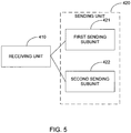
Fig. 4 , an example node includes a receivingunit 410 configured to obtain data to be transmitted. For a data source node, the receivingunit 410 is configured to obtain original data to be transmitted, and for a destination node, the receivingunit 410 is configured to receive the data to be transmitted that is sent from another node. The node additionally includes a sendingunit 420 configured to send, when the node for link data transmission has at least one child node, the data to be transmitted that is received by the receivingunit 410 to one of the at least one child node, and send when the node for link data transmission has at least one sibling node that has not obtained the data to be transmitted the data to be transmitted that is received by the receivingunit 410, to one of the at least one sibling node. - Referring to
Fig. 5 , the sendingunit 420 may include a first sendingsubunit 421 configured to send the data to be transmitted that is received by the receiving unit to the first child node that is connected with the node for link data transmission; and asecond sending subunit 422 configured to send the data to be transmitted that is received by the receiving unit to a node that succeeds the node for link data transmission and is the first node connected with the parent node of the node for link data transmission. - The above two sending subunits substantially represent a further optimization of the sending
unit 420. In the optimized mechanism, data is transferred to a node from the node at the same level that registers previously to it. This reflects the rule that a destination node sends data to a sibling node of it which has not obtained any data. Also, to determine the direction of data transmission according to the order in which the nodes register facilitates the management to the data transmission. - Referring to
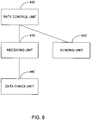
Fig. 6 , the node for link data transmission may further include: arate control unit 430 configured to control the data receiving rate of the receivingunit 410 and/or the data sending rate of the sendingunit 420. If the receiving unit receives the data to be transmitted that is sent from another node, the node for link data transmission may further include adata check unit 440 configured to check whether the data to be transmitted that is received by the receivingunit 410 is complete and if not, request the data sending node to resend the lost parts of the data. - The units described above can be implemented as software components executing on one or more general purpose processors, as hardware such as programmable logic devices and/or Application Specific Integrated Circuits designed to perform certain functions or a combination thereof. For example, in some embodiments, the sending unit and the receiving unit are implemented as communication interface hardware that execute supporting software and firmware. In some embodiments, the units can be embodied by a form of software products which can be stored in a nonvolatile storage medium (such as optical disk, flash storage device, mobile hard disk, etc.), including a number of instructions for making a computer device (such as personal computers, servers, network equipments, etc.) implement the methods described in the embodiments of the present invention. The units may be implemented on a single device or distributed across multiple devices. The functions of the units may be merged into one another or further split into multiple sub-units.
- The description of the device embodiments that substantially correspond to the method embodiments is relatively brief and reference may be made to the passages for the method embodiments for the details. The device embodiments described above are merely illustrative, where the units that are described as separate components may be or may not be physically separate from each other, and the components indicated as units may be or may not be physical units, and may be disposed at the same site, or distributed over multiple network elements. Parts or all of the modules may be selected as required to achieve the objects of the embodiments according to the present invention, which can be understood and implemented by those skilled in the art without inventive effort. In some embodiments, the device includes one or more processors and one or more memory for providing the processors) with instructions. The processors) are configured to perform the functions of the one or more units described above.
- The above are merely some specific embodiments of the present invention. Those skilled in the art can make various alterations and modifications without departing from the scope of the invention. Such alterations and modifications are intended to fall into the scope of the present invention.
- Although the foregoing embodiments have been described in some detail for purposes of clarity of understanding, the invention is not limited to the details provided. There are many alternative ways of implementing the invention. The disclosed embodiments are illustrative and not restrictive.
Claims (10)
- A method for link data transmission to a plurality of nodes, comprising:establishing a tree connection among the plurality of nodes;receiving data to be transmitted at a current node;in the event that the current node receiving the data to be transmitted has at least one child node, sending by the current node the data to be transmitted to one of the at least one child node; andin the event that the current node receiving the data to be transmitted has at least one sibling node that has not obtained the data to be transmitted, sending by the current node the data to be transmitted to one of the at least one sibling node; whereinsending by the current node the data to be transmitted to one of the at least one child node comprises sending the data to be transmitted to a first child node that establishes a connection with the current node; andsending the data to be transmitted to one of the at least one sibling node comprises sending the data to be transmitted to a node that is the first node, subsequent to the current node, to establish a connection with a parent node of the current node.
- The method of claim 1, further comprising controlling by the current node a data receiving rate.
- The method of claim 1, further comprising controlling by the current node a data sending rate to the at least one child node.
- The method of claim 1, further comprising controlling by the current node a data sending rate to the at least one sibling node.
- The method of claim 1, further comprising setting a destination node to which the current node sends the data to be transmitted as a current node, and receiving the data to be transmitted at the current node.
- The method of claim 1, wherein establishing a tree connection between nodes comprises connecting the nodes located in a single network with a single parent node.
- The method of claim 1, wherein a child node maintains a connection with a parent node by sending registration information to the parent node periodically.
- The method of claim 1, wherein receiving data to be transmitted by a current node comprises receiving by the current node the data to be transmitted that is sent from a data sending node, and the method further comprises: checking by the current node whether the received data to be transmitted is complete, and if not requesting the data sending node to resend lost parts of the data.
- A link data transmission node comprising:an interface configured to:receive data transmitted from a source node;a processor coupled to the interface, configured to determine whether the link data transmission node has at least one child node, and whether the link data transmission node has at least one sibling node that has not obtained the data to be transmitted; whereinin the event that the link data transmission node has at least one child node, the interface is further configured to send the data to one of the at least one child node; andin the event that the link data transmission node has at least one sibling node that has not obtained the data to be transmitted, the interface is further configured to send by the current node the data to be transmitted to one of the at least one sibling node; andsending by the current node the data to be transmitted to one of the at least one child node comprises sending the data to be transmitted to a first child node that establishes a connection with the current node; andsending the data to be transmitted to one of the at least one sibling node comprises sending the data to be transmitted to a node that is the first node, subsequent to the current node, to establish a connection with a parent node of the current node.
- A system for link data transmission, comprising
a data source node; and
a plurality of destination nodes; wherein:a tree connection is established between the data source node and the plurality of destination nodes;at least one data destination node is a child node of the data source node;the data source node is configured to send data to be transmitted to a child node of the data source node; andeach of the at least one data destination node is configured to:receive the data to be transmitted;in the event that the at least one data destination node has at least one child node of its own, send the received data to one of the at least one child node of its own; andin the event that the at least one data destination node has at least one sibling node that has not obtained the data to be transmitted, send the received data to the at least one of the at least one sibling node; andsending by the current node the data to be transmitted to one of the at least one child node comprises sending the data to be transmitted to a first child node that establishes a connection with the current node; andsending the data to be transmitted to one of the at least one sibling node comprises sending the data to be transmitted to a node that is the first node, subsequent to the current node, to establish a connection with a parent node of the current node.
Applications Claiming Priority (3)
| Application Number | Priority Date | Filing Date | Title |
|---|---|---|---|
| CN200810180167.5A CN101414949B (en) | 2008-11-28 | 2008-11-28 | Chain data transmission method, node and system |
| US12/592,342 US8379645B2 (en) | 2008-11-28 | 2009-11-23 | Link data transmission method, node and system |
| PCT/US2009/006264 WO2010062384A1 (en) | 2008-11-28 | 2009-11-24 | Link data transmission method, node and system |
Publications (3)
| Publication Number | Publication Date |
|---|---|
| EP2356753A1 EP2356753A1 (en) | 2011-08-17 |
| EP2356753A4 EP2356753A4 (en) | 2012-06-20 |
| EP2356753B1 true EP2356753B1 (en) | 2017-05-10 |
Family
ID=40595274
Family Applications (1)
| Application Number | Title | Priority Date | Filing Date |
|---|---|---|---|
| EP09829470.5A Active EP2356753B1 (en) | 2008-11-28 | 2009-11-24 | Link data transmission method, node and system |
Country Status (6)
| Country | Link |
|---|---|
| US (2) | US8379645B2 (en) |
| EP (1) | EP2356753B1 (en) |
| JP (1) | JP5274669B2 (en) |
| CN (1) | CN101414949B (en) |
| HK (1) | HK1129506A1 (en) |
| WO (1) | WO2010062384A1 (en) |
Families Citing this family (16)
| Publication number | Priority date | Publication date | Assignee | Title |
|---|---|---|---|---|
| CN101582826B (en) * | 2009-06-25 | 2011-05-04 | 北京洲洋伟业信息技术有限公司 | Data transmission method based on dynamic binary tree child-nephew two-channel in internet classroom |
| CN102201965A (en) * | 2010-03-24 | 2011-09-28 | 北京创世网赢高科技有限公司 | Data transmission method |
| US8909950B1 (en) | 2010-04-18 | 2014-12-09 | Aptima, Inc. | Systems and methods of power management |
| CN102201911B (en) * | 2011-05-18 | 2013-10-30 | 山东中创软件商用中间件股份有限公司 | Method and system for synchronously transmitting data |
| US9910904B2 (en) | 2011-08-30 | 2018-03-06 | International Business Machines Corporation | Replication of data objects from a source server to a target server |
| US9917739B2 (en) | 2012-02-20 | 2018-03-13 | Aptima, Inc. | Systems and methods for network pattern matching |
| CN102724121A (en) * | 2012-06-20 | 2012-10-10 | 上海琥智数码科技有限公司 | Distributed network data transmission method for LAN |
| CN104468483B (en) * | 2013-09-22 | 2019-01-22 | 腾讯科技(深圳)有限公司 | Data transmission method and system, control device and node apparatus |
| US10277512B1 (en) | 2015-02-03 | 2019-04-30 | State Farm Mutual Automobile Insurance Company | Method, device, and computer-readable medium for automatic network traffic engineering |
| US10725708B2 (en) | 2015-07-31 | 2020-07-28 | International Business Machines Corporation | Replication of versions of an object from a source storage to a target storage |
| WO2017035789A1 (en) * | 2015-09-01 | 2017-03-09 | 深圳好视网络科技有限公司 | Data transmission method and system |
| CN105337830B (en) * | 2015-10-15 | 2019-06-11 | 中国石油天然气集团公司 | Data transmission network and data transmission method |
| CN106530103A (en) * | 2016-10-11 | 2017-03-22 | 北京农业智能装备技术研究中心 | Aviation plant protection operation real-time supervision system |
| CN108268289B (en) * | 2016-12-30 | 2022-01-28 | 阿里巴巴集团控股有限公司 | Parameter configuration method, device and system for web application |
| CN112751885A (en) * | 2019-10-29 | 2021-05-04 | 贵州白山云科技股份有限公司 | Data transmission system and method |
| CN115242839B (en) * | 2022-07-20 | 2023-11-10 | 北京天融信网络安全技术有限公司 | Method and device for cascade data transmission of Internet of things, electronic equipment and storage medium |
Family Cites Families (17)
| Publication number | Priority date | Publication date | Assignee | Title |
|---|---|---|---|---|
| JPH08130551A (en) | 1994-11-02 | 1996-05-21 | Ekushingu:Kk | Hierarchical network for data communication |
| JP3222086B2 (en) * | 1997-04-07 | 2001-10-22 | 矢崎総業株式会社 | Tree structure address setting method and system |
| US6735633B1 (en) * | 1999-06-01 | 2004-05-11 | Fast Forward Networks | System for bandwidth allocation in a computer network |
| EP1371180B1 (en) * | 2001-03-09 | 2006-12-06 | Koninklijke Philips Electronics N.V. | System of apparatuses that communicate via a bus structure |
| AU2002363148A1 (en) * | 2001-10-31 | 2003-05-12 | Blue Falcon Networks, Inc. | Data transmission process and system |
| US7577750B2 (en) * | 2003-05-23 | 2009-08-18 | Microsoft Corporation | Systems and methods for peer-to-peer collaboration to enhance multimedia streaming |
| US20050007964A1 (en) * | 2003-07-01 | 2005-01-13 | Vincent Falco | Peer-to-peer network heartbeat server and associated methods |
| US20050108356A1 (en) * | 2003-10-31 | 2005-05-19 | Marcel-Catalin Rosu | Method and apparatus for bandwidth efficient distribution of content |
| KR20050047570A (en) | 2003-11-18 | 2005-05-23 | 현대자동차주식회사 | System for operating ventilation devices of vehicle |
| CN100346617C (en) * | 2004-01-14 | 2007-10-31 | 电子科技大学 | Nucleus tree self-organizing dynamic route algorithm |
| KR100667318B1 (en) * | 2004-02-12 | 2007-01-12 | 삼성전자주식회사 | Method of multicast in ZigBee network |
| US20060146875A1 (en) * | 2005-01-04 | 2006-07-06 | Yang Luiyang L | Media access controller and methods for distributed hop-by-hop flow control in wireless mesh networks |
| JP4517885B2 (en) * | 2005-02-23 | 2010-08-04 | 日本電気株式会社 | Network reconfiguration method, program, information recording medium, node, base station, multi-hop network system |
| CN100493085C (en) * | 2005-07-08 | 2009-05-27 | 清华大学 | P2P worm defending system |
| US7457257B2 (en) * | 2005-11-17 | 2008-11-25 | International Business Machines Corporation | Apparatus, system, and method for reliable, fast, and scalable multicast message delivery in service overlay networks |
| KR100733987B1 (en) * | 2005-11-21 | 2007-06-29 | 한국전자통신연구원 | Multiple-Forwarder based File Distribution Schemes using Join Time Interval |
| US7657648B2 (en) * | 2007-06-21 | 2010-02-02 | Microsoft Corporation | Hybrid tree/mesh overlay for data delivery |
-
2008
- 2008-11-28 CN CN200810180167.5A patent/CN101414949B/en not_active Expired - Fee Related
-
2009
- 2009-09-29 HK HK09109022.4A patent/HK1129506A1/en unknown
- 2009-11-23 US US12/592,342 patent/US8379645B2/en active Active
- 2009-11-24 JP JP2011538600A patent/JP5274669B2/en active Active
- 2009-11-24 WO PCT/US2009/006264 patent/WO2010062384A1/en active Application Filing
- 2009-11-24 EP EP09829470.5A patent/EP2356753B1/en active Active
-
2013
- 2013-01-14 US US13/740,750 patent/US8743881B2/en active Active
Also Published As
| Publication number | Publication date |
|---|---|
| JP2012510759A (en) | 2012-05-10 |
| US20130128775A1 (en) | 2013-05-23 |
| HK1129506A1 (en) | 2009-11-27 |
| JP5274669B2 (en) | 2013-08-28 |
| EP2356753A4 (en) | 2012-06-20 |
| US20100142547A1 (en) | 2010-06-10 |
| US8743881B2 (en) | 2014-06-03 |
| EP2356753A1 (en) | 2011-08-17 |
| CN101414949A (en) | 2009-04-22 |
| WO2010062384A1 (en) | 2010-06-03 |
| US8379645B2 (en) | 2013-02-19 |
| CN101414949B (en) | 2011-05-18 |
Similar Documents
| Publication | Publication Date | Title |
|---|---|---|
| EP2356753B1 (en) | Link data transmission method, node and system | |
| US8537660B2 (en) | High availability transport protocol method and apparatus | |
| US8149691B1 (en) | Push-based hierarchical state propagation within a multi-chassis network device | |
| US7804769B1 (en) | Non-stop forwarding in a multi-chassis router | |
| CN106656784B (en) | Data stream propagation system and method for block chain network | |
| CN101573940B (en) | System and method for TCP high availability | |
| JP6164747B2 (en) | Method for flow control in a collaborative environment and for reliable communication | |
| CN104811459A (en) | Processing method, processing device and system for message services and message service system | |
| CN110708175B (en) | Method for synchronizing messages in a distributed network | |
| US7020717B1 (en) | System and method for resynchronizing interprocess communications connection between consumer and publisher applications by using a shared state memory among message topic server and message routers | |
| CN105229975A (en) | Based on the Internet Transmission adjustment of applying the transmission unit data provided | |
| CN106059936A (en) | Method and device for multicasting files in cloud system | |
| JP6899837B2 (en) | Data transmission across regions | |
| US7428589B2 (en) | Network system, network control method, and signal sender/receiver | |
| CN102427474B (en) | Data transmission system in cloud storage | |
| CN112019599A (en) | Method and device for synchronizing processing messages during block chain consensus processing | |
| TWI477112B (en) | Chain data transmission method, node and system | |
| JP2004157753A (en) | Firmware download system | |
| JP5331897B2 (en) | COMMUNICATION METHOD, INFORMATION PROCESSING DEVICE, AND PROGRAM | |
| Bhuvana Suganth et al. | Fault tolerance communication in mobile distributed networks | |
| JP2010251911A (en) | Internode data response system | |
| Fang et al. | EDTS: An Extensible Data Transmission Service for the Internet |
Legal Events
| Date | Code | Title | Description |
|---|---|---|---|
| PUAI | Public reference made under article 153(3) epc to a published international application that has entered the european phase |
Free format text: ORIGINAL CODE: 0009012 |
|
| 17P | Request for examination filed |
Effective date: 20110613 |
|
| AK | Designated contracting states |
Kind code of ref document: A1 Designated state(s): AT BE BG CH CY CZ DE DK EE ES FI FR GB GR HR HU IE IS IT LI LT LU LV MC MK MT NL NO PL PT RO SE SI SK SM TR |
|
| DAX | Request for extension of the european patent (deleted) | ||
| A4 | Supplementary search report drawn up and despatched |
Effective date: 20120522 |
|
| RIC1 | Information provided on ipc code assigned before grant |
Ipc: H04B 7/00 20060101AFI20120515BHEP |
|
| GRAP | Despatch of communication of intention to grant a patent |
Free format text: ORIGINAL CODE: EPIDOSNIGR1 |
|
| INTG | Intention to grant announced |
Effective date: 20161215 |
|
| GRAS | Grant fee paid |
Free format text: ORIGINAL CODE: EPIDOSNIGR3 |
|
| GRAA | (expected) grant |
Free format text: ORIGINAL CODE: 0009210 |
|
| AK | Designated contracting states |
Kind code of ref document: B1 Designated state(s): AT BE BG CH CY CZ DE DK EE ES FI FR GB GR HR HU IE IS IT LI LT LU LV MC MK MT NL NO PL PT RO SE SI SK SM TR |
|
| REG | Reference to a national code |
Ref country code: GB Ref legal event code: FG4D |
|
| REG | Reference to a national code |
Ref country code: AT Ref legal event code: REF Ref document number: 893316 Country of ref document: AT Kind code of ref document: T Effective date: 20170515 Ref country code: CH Ref legal event code: EP |
|
| REG | Reference to a national code |
Ref country code: IE Ref legal event code: FG4D |
|
| REG | Reference to a national code |
Ref country code: DE Ref legal event code: R096 Ref document number: 602009046073 Country of ref document: DE |
|
| REG | Reference to a national code |
Ref country code: NL Ref legal event code: MP Effective date: 20170510 |
|
| REG | Reference to a national code |
Ref country code: LT Ref legal event code: MG4D |
|
| REG | Reference to a national code |
Ref country code: AT Ref legal event code: MK05 Ref document number: 893316 Country of ref document: AT Kind code of ref document: T Effective date: 20170510 |
|
| PG25 | Lapsed in a contracting state [announced via postgrant information from national office to epo] |
Ref country code: FI Free format text: LAPSE BECAUSE OF FAILURE TO SUBMIT A TRANSLATION OF THE DESCRIPTION OR TO PAY THE FEE WITHIN THE PRESCRIBED TIME-LIMIT Effective date: 20170510 Ref country code: ES Free format text: LAPSE BECAUSE OF FAILURE TO SUBMIT A TRANSLATION OF THE DESCRIPTION OR TO PAY THE FEE WITHIN THE PRESCRIBED TIME-LIMIT Effective date: 20170510 Ref country code: LT Free format text: LAPSE BECAUSE OF FAILURE TO SUBMIT A TRANSLATION OF THE DESCRIPTION OR TO PAY THE FEE WITHIN THE PRESCRIBED TIME-LIMIT Effective date: 20170510 Ref country code: HR Free format text: LAPSE BECAUSE OF FAILURE TO SUBMIT A TRANSLATION OF THE DESCRIPTION OR TO PAY THE FEE WITHIN THE PRESCRIBED TIME-LIMIT Effective date: 20170510 Ref country code: AT Free format text: LAPSE BECAUSE OF FAILURE TO SUBMIT A TRANSLATION OF THE DESCRIPTION OR TO PAY THE FEE WITHIN THE PRESCRIBED TIME-LIMIT Effective date: 20170510 Ref country code: GR Free format text: LAPSE BECAUSE OF FAILURE TO SUBMIT A TRANSLATION OF THE DESCRIPTION OR TO PAY THE FEE WITHIN THE PRESCRIBED TIME-LIMIT Effective date: 20170811 Ref country code: NO Free format text: LAPSE BECAUSE OF FAILURE TO SUBMIT A TRANSLATION OF THE DESCRIPTION OR TO PAY THE FEE WITHIN THE PRESCRIBED TIME-LIMIT Effective date: 20170810 |
|
| REG | Reference to a national code |
Ref country code: FR Ref legal event code: PLFP Year of fee payment: 9 |
|
| PG25 | Lapsed in a contracting state [announced via postgrant information from national office to epo] |
Ref country code: SE Free format text: LAPSE BECAUSE OF FAILURE TO SUBMIT A TRANSLATION OF THE DESCRIPTION OR TO PAY THE FEE WITHIN THE PRESCRIBED TIME-LIMIT Effective date: 20170510 Ref country code: BG Free format text: LAPSE BECAUSE OF FAILURE TO SUBMIT A TRANSLATION OF THE DESCRIPTION OR TO PAY THE FEE WITHIN THE PRESCRIBED TIME-LIMIT Effective date: 20170810 Ref country code: PL Free format text: LAPSE BECAUSE OF FAILURE TO SUBMIT A TRANSLATION OF THE DESCRIPTION OR TO PAY THE FEE WITHIN THE PRESCRIBED TIME-LIMIT Effective date: 20170510 Ref country code: LV Free format text: LAPSE BECAUSE OF FAILURE TO SUBMIT A TRANSLATION OF THE DESCRIPTION OR TO PAY THE FEE WITHIN THE PRESCRIBED TIME-LIMIT Effective date: 20170510 Ref country code: IS Free format text: LAPSE BECAUSE OF FAILURE TO SUBMIT A TRANSLATION OF THE DESCRIPTION OR TO PAY THE FEE WITHIN THE PRESCRIBED TIME-LIMIT Effective date: 20170910 Ref country code: NL Free format text: LAPSE BECAUSE OF FAILURE TO SUBMIT A TRANSLATION OF THE DESCRIPTION OR TO PAY THE FEE WITHIN THE PRESCRIBED TIME-LIMIT Effective date: 20170510 |
|
| PG25 | Lapsed in a contracting state [announced via postgrant information from national office to epo] |
Ref country code: EE Free format text: LAPSE BECAUSE OF FAILURE TO SUBMIT A TRANSLATION OF THE DESCRIPTION OR TO PAY THE FEE WITHIN THE PRESCRIBED TIME-LIMIT Effective date: 20170510 Ref country code: RO Free format text: LAPSE BECAUSE OF FAILURE TO SUBMIT A TRANSLATION OF THE DESCRIPTION OR TO PAY THE FEE WITHIN THE PRESCRIBED TIME-LIMIT Effective date: 20170510 Ref country code: CZ Free format text: LAPSE BECAUSE OF FAILURE TO SUBMIT A TRANSLATION OF THE DESCRIPTION OR TO PAY THE FEE WITHIN THE PRESCRIBED TIME-LIMIT Effective date: 20170510 Ref country code: DK Free format text: LAPSE BECAUSE OF FAILURE TO SUBMIT A TRANSLATION OF THE DESCRIPTION OR TO PAY THE FEE WITHIN THE PRESCRIBED TIME-LIMIT Effective date: 20170510 Ref country code: SK Free format text: LAPSE BECAUSE OF FAILURE TO SUBMIT A TRANSLATION OF THE DESCRIPTION OR TO PAY THE FEE WITHIN THE PRESCRIBED TIME-LIMIT Effective date: 20170510 |
|
| REG | Reference to a national code |
Ref country code: DE Ref legal event code: R097 Ref document number: 602009046073 Country of ref document: DE |
|
| PG25 | Lapsed in a contracting state [announced via postgrant information from national office to epo] |
Ref country code: SM Free format text: LAPSE BECAUSE OF FAILURE TO SUBMIT A TRANSLATION OF THE DESCRIPTION OR TO PAY THE FEE WITHIN THE PRESCRIBED TIME-LIMIT Effective date: 20170510 Ref country code: IT Free format text: LAPSE BECAUSE OF FAILURE TO SUBMIT A TRANSLATION OF THE DESCRIPTION OR TO PAY THE FEE WITHIN THE PRESCRIBED TIME-LIMIT Effective date: 20170510 |
|
| PLBE | No opposition filed within time limit |
Free format text: ORIGINAL CODE: 0009261 |
|
| STAA | Information on the status of an ep patent application or granted ep patent |
Free format text: STATUS: NO OPPOSITION FILED WITHIN TIME LIMIT |
|
| 26N | No opposition filed |
Effective date: 20180213 |
|
| PG25 | Lapsed in a contracting state [announced via postgrant information from national office to epo] |
Ref country code: SI Free format text: LAPSE BECAUSE OF FAILURE TO SUBMIT A TRANSLATION OF THE DESCRIPTION OR TO PAY THE FEE WITHIN THE PRESCRIBED TIME-LIMIT Effective date: 20170510 |
|
| PG25 | Lapsed in a contracting state [announced via postgrant information from national office to epo] |
Ref country code: MC Free format text: LAPSE BECAUSE OF FAILURE TO SUBMIT A TRANSLATION OF THE DESCRIPTION OR TO PAY THE FEE WITHIN THE PRESCRIBED TIME-LIMIT Effective date: 20170510 |
|
| PG25 | Lapsed in a contracting state [announced via postgrant information from national office to epo] |
Ref country code: LI Free format text: LAPSE BECAUSE OF NON-PAYMENT OF DUE FEES Effective date: 20171130 Ref country code: CH Free format text: LAPSE BECAUSE OF NON-PAYMENT OF DUE FEES Effective date: 20171130 |
|
| PG25 | Lapsed in a contracting state [announced via postgrant information from national office to epo] |
Ref country code: LU Free format text: LAPSE BECAUSE OF NON-PAYMENT OF DUE FEES Effective date: 20171124 |
|
| REG | Reference to a national code |
Ref country code: BE Ref legal event code: MM Effective date: 20171130 |
|
| REG | Reference to a national code |
Ref country code: IE Ref legal event code: MM4A |
|
| PG25 | Lapsed in a contracting state [announced via postgrant information from national office to epo] |
Ref country code: MT Free format text: LAPSE BECAUSE OF NON-PAYMENT OF DUE FEES Effective date: 20171124 |
|
| PG25 | Lapsed in a contracting state [announced via postgrant information from national office to epo] |
Ref country code: IE Free format text: LAPSE BECAUSE OF NON-PAYMENT OF DUE FEES Effective date: 20171124 |
|
| PG25 | Lapsed in a contracting state [announced via postgrant information from national office to epo] |
Ref country code: BE Free format text: LAPSE BECAUSE OF NON-PAYMENT OF DUE FEES Effective date: 20171130 |
|
| PG25 | Lapsed in a contracting state [announced via postgrant information from national office to epo] |
Ref country code: HU Free format text: LAPSE BECAUSE OF FAILURE TO SUBMIT A TRANSLATION OF THE DESCRIPTION OR TO PAY THE FEE WITHIN THE PRESCRIBED TIME-LIMIT; INVALID AB INITIO Effective date: 20091124 |
|
| PG25 | Lapsed in a contracting state [announced via postgrant information from national office to epo] |
Ref country code: CY Free format text: LAPSE BECAUSE OF NON-PAYMENT OF DUE FEES Effective date: 20170510 |
|
| PG25 | Lapsed in a contracting state [announced via postgrant information from national office to epo] |
Ref country code: MK Free format text: LAPSE BECAUSE OF FAILURE TO SUBMIT A TRANSLATION OF THE DESCRIPTION OR TO PAY THE FEE WITHIN THE PRESCRIBED TIME-LIMIT Effective date: 20170510 |
|
| PG25 | Lapsed in a contracting state [announced via postgrant information from national office to epo] |
Ref country code: TR Free format text: LAPSE BECAUSE OF FAILURE TO SUBMIT A TRANSLATION OF THE DESCRIPTION OR TO PAY THE FEE WITHIN THE PRESCRIBED TIME-LIMIT Effective date: 20170510 |
|
| PG25 | Lapsed in a contracting state [announced via postgrant information from national office to epo] |
Ref country code: PT Free format text: LAPSE BECAUSE OF FAILURE TO SUBMIT A TRANSLATION OF THE DESCRIPTION OR TO PAY THE FEE WITHIN THE PRESCRIBED TIME-LIMIT Effective date: 20170510 |
|
| P01 | Opt-out of the competence of the unified patent court (upc) registered |
Effective date: 20230418 |
|
| PGFP | Annual fee paid to national office [announced via postgrant information from national office to epo] |
Ref country code: GB Payment date: 20231127 Year of fee payment: 15 |
|
| PGFP | Annual fee paid to national office [announced via postgrant information from national office to epo] |
Ref country code: FR Payment date: 20231127 Year of fee payment: 15 Ref country code: DE Payment date: 20231129 Year of fee payment: 15 |