EP2356362B1 - Apparatus for use in laying pipe on the sea floor - Google Patents
Apparatus for use in laying pipe on the sea floor Download PDFInfo
- Publication number
- EP2356362B1 EP2356362B1 EP09781750.6A EP09781750A EP2356362B1 EP 2356362 B1 EP2356362 B1 EP 2356362B1 EP 09781750 A EP09781750 A EP 09781750A EP 2356362 B1 EP2356362 B1 EP 2356362B1
- Authority
- EP
- European Patent Office
- Prior art keywords
- pipe
- clamping device
- clamp
- pipelay vessel
- hold
- Prior art date
- Legal status (The legal status is an assumption and is not a legal conclusion. Google has not performed a legal analysis and makes no representation as to the accuracy of the status listed.)
- Not-in-force
Links
- 241001589086 Bellapiscis medius Species 0.000 claims description 26
- 238000000034 method Methods 0.000 claims description 16
- 238000010276 construction Methods 0.000 claims description 12
- 238000013016 damping Methods 0.000 claims description 7
- 238000005304 joining Methods 0.000 claims description 4
- 238000005520 cutting process Methods 0.000 claims description 2
- 238000007667 floating Methods 0.000 claims description 2
- 238000012544 monitoring process Methods 0.000 claims description 2
- 230000000284 resting effect Effects 0.000 claims 1
- 230000007246 mechanism Effects 0.000 description 4
- 238000013461 design Methods 0.000 description 3
- 238000012360 testing method Methods 0.000 description 3
- XLYOFNOQVPJJNP-UHFFFAOYSA-N water Substances O XLYOFNOQVPJJNP-UHFFFAOYSA-N 0.000 description 3
- 230000008878 coupling Effects 0.000 description 2
- 238000010168 coupling process Methods 0.000 description 2
- 238000005859 coupling reaction Methods 0.000 description 2
- 239000004033 plastic Substances 0.000 description 2
- 230000008569 process Effects 0.000 description 2
- 238000003466 welding Methods 0.000 description 2
- IJGRMHOSHXDMSA-UHFFFAOYSA-N Atomic nitrogen Chemical compound N#N IJGRMHOSHXDMSA-UHFFFAOYSA-N 0.000 description 1
- 230000002411 adverse Effects 0.000 description 1
- 238000013459 approach Methods 0.000 description 1
- 230000008859 change Effects 0.000 description 1
- 229910001873 dinitrogen Inorganic materials 0.000 description 1
- 230000000694 effects Effects 0.000 description 1
- 230000007613 environmental effect Effects 0.000 description 1
- 239000012530 fluid Substances 0.000 description 1
- 238000003780 insertion Methods 0.000 description 1
- 230000037431 insertion Effects 0.000 description 1
- 238000009434 installation Methods 0.000 description 1
- 238000004519 manufacturing process Methods 0.000 description 1
- 230000010355 oscillation Effects 0.000 description 1
- 238000011084 recovery Methods 0.000 description 1
- 230000008439 repair process Effects 0.000 description 1
- 230000000717 retained effect Effects 0.000 description 1
- 230000035939 shock Effects 0.000 description 1
Images


Classifications
-
- F—MECHANICAL ENGINEERING; LIGHTING; HEATING; WEAPONS; BLASTING
- F16—ENGINEERING ELEMENTS AND UNITS; GENERAL MEASURES FOR PRODUCING AND MAINTAINING EFFECTIVE FUNCTIONING OF MACHINES OR INSTALLATIONS; THERMAL INSULATION IN GENERAL
- F16L—PIPES; JOINTS OR FITTINGS FOR PIPES; SUPPORTS FOR PIPES, CABLES OR PROTECTIVE TUBING; MEANS FOR THERMAL INSULATION IN GENERAL
- F16L1/00—Laying or reclaiming pipes; Repairing or joining pipes on or under water
- F16L1/12—Laying or reclaiming pipes on or under water
- F16L1/20—Accessories therefor, e.g. floats or weights
- F16L1/23—Pipe tensioning apparatus
-
- F—MECHANICAL ENGINEERING; LIGHTING; HEATING; WEAPONS; BLASTING
- F16—ENGINEERING ELEMENTS AND UNITS; GENERAL MEASURES FOR PRODUCING AND MAINTAINING EFFECTIVE FUNCTIONING OF MACHINES OR INSTALLATIONS; THERMAL INSULATION IN GENERAL
- F16L—PIPES; JOINTS OR FITTINGS FOR PIPES; SUPPORTS FOR PIPES, CABLES OR PROTECTIVE TUBING; MEANS FOR THERMAL INSULATION IN GENERAL
- F16L1/00—Laying or reclaiming pipes; Repairing or joining pipes on or under water
- F16L1/12—Laying or reclaiming pipes on or under water
- F16L1/16—Laying or reclaiming pipes on or under water on the bottom
- F16L1/18—Laying or reclaiming pipes on or under water on the bottom the pipes being S- or J-shaped and under tension during laying
- F16L1/19—Laying or reclaiming pipes on or under water on the bottom the pipes being S- or J-shaped and under tension during laying the pipes being J-shaped
-
- F—MECHANICAL ENGINEERING; LIGHTING; HEATING; WEAPONS; BLASTING
- F16—ENGINEERING ELEMENTS AND UNITS; GENERAL MEASURES FOR PRODUCING AND MAINTAINING EFFECTIVE FUNCTIONING OF MACHINES OR INSTALLATIONS; THERMAL INSULATION IN GENERAL
- F16L—PIPES; JOINTS OR FITTINGS FOR PIPES; SUPPORTS FOR PIPES, CABLES OR PROTECTIVE TUBING; MEANS FOR THERMAL INSULATION IN GENERAL
- F16L1/00—Laying or reclaiming pipes; Repairing or joining pipes on or under water
- F16L1/12—Laying or reclaiming pipes on or under water
- F16L1/20—Accessories therefor, e.g. floats or weights
- F16L1/202—Accessories therefor, e.g. floats or weights fixed on or to vessels
-
- F—MECHANICAL ENGINEERING; LIGHTING; HEATING; WEAPONS; BLASTING
- F16—ENGINEERING ELEMENTS AND UNITS; GENERAL MEASURES FOR PRODUCING AND MAINTAINING EFFECTIVE FUNCTIONING OF MACHINES OR INSTALLATIONS; THERMAL INSULATION IN GENERAL
- F16L—PIPES; JOINTS OR FITTINGS FOR PIPES; SUPPORTS FOR PIPES, CABLES OR PROTECTIVE TUBING; MEANS FOR THERMAL INSULATION IN GENERAL
- F16L1/00—Laying or reclaiming pipes; Repairing or joining pipes on or under water
- F16L1/12—Laying or reclaiming pipes on or under water
- F16L1/20—Accessories therefor, e.g. floats or weights
- F16L1/235—Apparatus for controlling the pipe during laying
Definitions
- This torque needs to be released before undertaking a pipe joining operation, and/or the attachment of in-line and/or end modules etc. This is particularly the case for in-line modules, which are launched in a preferred orientation relative to the sea floor, as any residual torque in the pipes can adversely affect their alignment for the final lay down process on the sea floor.
- a current torque release technique involves attaching an Abandonment and Recovery (A&R) winch line via a swivel to the pipe end whilst the latter is retained by clamps in the HOC. The load is then taken up on the A&R winch, the HOC clamps are retracted, and the twist is taken out by the swivel.
- A&R Abandonment and Recovery
- This approach involves fixing an A&R attachment head to the pipe end by means of high quality welds. This task can take several hours of valuable vessel time and it is not possible to load test this joint prior to use.
- Weather vaning of the pipelay vessel is not specifically addressed by either the A&R based system, or by the twister system, but both are capable of it.
- the present invention is concerned with providing an alternative to the A&R and twister systems, and in particular to avoid the need to rig and use the A&R winch system, and thus to decrease the timescales involved.
- GB 2019976 discloses an arrangement designed to keep a pipeline position stable even if a ship on which the pipeline end is located moves.
- a trolley secures the top end of a pipeline with securing wedges - lower parts of the pipeline rest on a slide.
- the trolley is movable on circular rails on the vessel by rollers.
- the slide is held on three further sets of rollers on circular rails below platform level, with the slide progressively inclined.
- the middle set of rollers has a drivable crown gear and gear train attached.
- US 5181798 teaches an arrangement designed for use in pipeline repair, allowing ship to change direction while the pipe is being supported.
- a rotatable turntable on the ship is adapted to hold pipes of different diameter and to rotate them into position for support against the inner diameter of a stinger.
- a pipelay vessel comprising a hold off clamp for disposal on the pipelay vessel and comprising a clamping device for securement to a pipe under lay at a position along a lay path, wherein the hold off clamp is adapted for controllable relative rotation with the lay path as a rotation axis while supporting a weight of a pipe being laid on the sea floor from the pipelay vessel, the hold off clamp comprising: a clamping device adapted to clamp and to support the weight of the laid pipe, a housing secured to the pipelay vessel, and an arrangement for providing controllable relative rotation of a clamped pipe relative to the pipelay vessel with the lay path as a rotation axis, the arrangement comprising a drive motor capable of providing predetermined rotation and torsional damping and a brake assembly capable of preventing said relative rotation comprising a brake actuator and disc pads mounted to the housing and co-operable with a projection of the clamping device comprising a brake disc.
- the means adapted to provide controllable relative rotation of the clamping means within the housing may comprise thrust bearings via which the clamping means is mounted on the housing.
- the drive means may comprise means mounted to the housing and co-operable with means of the clamping means.
- the clamping means may be hydraulically operable.
- the hold off clamp may include means for releasably connecting the clamping means to a hydraulic supply of the pipelay vessel.
- Means may be mounted to the clamping means for co-rotation therewith, for maintaining the clamping means secured to the pipe when the releasable connecting means are disconnected.
- the clamping means may comprise a plurality of clamping jaws disposed around the circumference of the pipe in use thereof and operable by clamping cylinders orthogonal to the pipe to grip the pipe.
- the clamping means may comprise a plurality of clamping jaws disposed around the circumference of the pipe in use thereof and operable by radius arms pivotably mounted to the clamping jaws and the body of the clamping means, initial grip of the pipe being achieved by pivoting of the radius arms caused by respective operating cylinders, and subsequent grip being maintained by the weight of the pipe.
- clamping means Mounted to the clamping means and co-rotational therewith may be telemetry means for monitoring the clamping means holding pressure and/or adjusting the drive means.
- the clamping means and the housing may be in the form of a split structure to facilitate disposal around the pipe.
- one said hold off clamp may be adapted to secure the outer pipe and another said hold off clamp may be adapted to support the inner pipe.
- the hold off clamp may be adapted to secure the outer pipe and a twister arrangement may be provided and employed to secure the inner pipe and adapted to support the weight of the inner pipe.
- a method for use in connection with the laying of pipe on the sea floor from a floating pipelay vessel wherein the pipelay vessel comprises a hold off clamp for disposal on the pipelay vessel and comprising a clamping device for securement to a pipe under lay at a position along a lay path, wherein the hold off clamp further comprises a housing secured to the pipelay vessel, wherein the clamping device is adapted to clamp and to support the weight of the laid pipe, the hold off clamp further comprising an arrangement for providing controllable relative rotation of a clamped pipe relative to the pipelay vessel with the lay path as a rotation axis, the method comprising: clamping the pipe in the clamping device; cutting the pipe above the clamping device so that the laid pipe is supported by the clamping device; and controlling relative rotation of the clamping device with respect to the pipelay vessel with the lay path as a rotation axis.
- Relative rotation may be performed and controlled in order to relieve residual torsion in the pipe.
- Relative rotation may serve to permit weather vaning of the pipelay vessel about the pipe.
- the outer pipe may be secured by the housing means and the clamping means, and the method may include the steps of mounting a further device to the pipelay vessel, which further device serves to secure the inner pipe and support its weight.
- the further device may comprise a respective housing means and clamping means.
- the further device may comprise a twister arrangement.
- the pipe end is first gripped at approximately deck level of the pipe laying vessel by a hold off clamp. This retains it against the load of the pipe suspended between it and the sea floor. The latter is a force of the order of two to three hundred tonnes.
- a pipe 1 can be held by a rotatable hold off clamp 2 which comprises a hold off clamp clamping means 3 mounted on thrust bearings 4, all supported by a housing or chassis 5.
- the chassis is mounted to the structure of the vessel, illustrated schematically at 6, which may comprise part of a deploying/stowing mechanism described further in connection with Figure 3 .
- the rotatable hold off clamp of the present invention has a hinged/split structure so that it can be opened to accept a pipe 1, closed around it, and then locked shut.
- Such an openable structure will also allow the through passage of smaller items attached to the pipe 1, for example anodes.
- hinged/split structure can be appreciated from Figure 2a or 2b which show the closed configuration in solid lines, and the opened configuration in dashed lines, in a plan view.
- the hold off clamp comprises two sections 7 with a clamp hinge 8 so that the sections 7 are openable, and is mounted to the vessel structure 6.
- Hydraulic operating cylinders 9 are illustrated as comprising means for controlling the opening and closing operation of the hold off clamp sections 7.
- the clamping means 3, the chassis 5 and the thrust bearings 4 will be of a suitably split design.
- a conventional hold off clamp may also have a split design but does not include the thrust bearings.
- FIG. 2a there are three clamping jaws 10 disposed around the circumference of the pipe to be clamped, and as illustrated in Figure 1 there may be three such sets of clamping jaws disposed along the length of the pipe.
- the clamping jaws are operated by hydraulic clamping cylinders 11 in the embodiment illustrated in Figure 1 , and the clamping jaws 10 are positioned orthogonally to and around the pipe. In the case of a set of three clamping jaws around the pipe, one clamp will be of a split construction and this is adjacent to the hinge 8 and provides the base against which the pipe is pushed by the other two clamping jaws.
- the set of clamping jaws comprises four clamping jaws 10, as illustrated in Figure 2b , in which case no clamping jaw which is split is required, thus facilitating manufacture and operation.
- the clamping jaws may be plastic/rubber lined or have teeth as illustrated in Figures 4b and 4c in connection with an alternative type of structure.
- the clamping means 3 is mounted on the chassis 5 via thrust bearings 4.
- the thrust bearings 4 mean that the clamping means 3 is free to rotate relative to the chassis 5 and the vessel 6 on which it is mounted, in order to remove the residual twist in the pipe and allow the vessel to "weather vane" about the pipe.
- the torque relief operation will be controlled by a brake assembly 12, and/or a rotary damper and drive motor 13, so that stored energy in the pipe can be relieved in a controllable manner.
- An annular projection 14 of the clamping means 3 may form a brake disc in the illustrated case of a disc brake assembly.
- the rotation characteristics of the clamping means 3 during pipe torque release can be controlled by the rotary damper 13 which engages with a toothed annular section 15 of the clamping means 3, which can alternatively be driven by the drive motor incorporated in the rotary damper. This also allows the pipe 1 to be twisted if required.
- Such a drive facility permits the alignment of pipe joint faces for welding, for example.
- the rotatable hold off clamp 2 may be mounted so that it can be swung clear of the line (lay path) adopted by a pipe during laying, in order to allow the passage of large items that may be attached to the pipe, for example in-line modules, pipeline end terminations (PLETs) etc.
- line lay path
- PLETs pipeline end terminations
- Figure 3 shows a deploying/stowing mechanism for the rotatable hold off clamp 2.
- the solid lines of the drawings illustrate the deployed position and the dashed lines indicate the stowed position.
- the rotatable hold off clamp 2 is illustrated as fixed directly to the vessel structure 6, in Figure 3 there is illustrated an intermediate deploying/stowing mechanism 16 comprising swinging arms 17 attached to the chassis 5 and the vessel structure 6 and positions of which are controlled by operating cylinders 18 which cause the rotatable hold off clamp to be moved between the deployed and stowed positions.
- Three or four sets of jaws may be set around the pipe 1 as was described for the orthogonal clamps, but in this case the jaws are connected to radius arms 19 which are pivotably mounted at one end to the jaw per se 10 and at the other end to body 20 of the clamping means.
- the jaws 10 are pulled onto the pipe 1 by operating cylinders 21 to create an initial grip.
- the jaws 10 then work in combination with the radius arms 19 so that the weight of the pipe 1 acting on the jaws increases the grip in the correct proportion to prevent slip, but at the same time over-stressing of the pipe wall is avoided. Consequently having generated the initial grip, further input from the operating cylinders 21 is not required.
- the jaws 10 may be plastic/rubber lined as illustrated schematically in Figure 4b , or have teeth as illustrated schematically in Figure 4c .
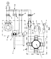
- the rotatable hold off clamp 2 may be driven by hydraulic power supplied over an hydraulic circuit 46 from the lay vessel, as illustrated schematically in Figure 5 .
- An orthogonal clamp arrangement is illustrated in Figure 5 , but the arrangement for the self gripping jaws of Figure 4a will be similar, except that the hydraulic fluid will be directed to the radius arm operating cylinders 21, rather than the clamping cylinders 11, from a clamping control valve 22 whose operating position determines whether the pipe is gripped or released, the clamping control valve 22 additionally having an off position.
- the telemetry module may be connected to the rotary damper 13 by a control line 28 in order to control the torsion damping and rotation as required.
- This control line may be hydraulic or electrical.
- FIG. 5 The schematic illustration in Figure 5 indicates within box 29 those elements which are mounted on the hold off clamp rotatable assembly 30, and within box 31 those elements mounted on the hold off clamp chassis 5, in particular the brake assembly 12 and the rotary damper and drive motor 13.
- the vessel's (ship's) hydraulic supply (not shown) is connected to the operating cylinders 9 via hold off clamp open/shut control valve 32, the brake assembly 12 via a brake control on/release/off valve 33, and to the rotary damper and drive motor 13 via a drive control left/right/off valve 34.
- the rotation of the rotatable assembly can be controlled by the brake and rotary damper.
- the brake enables locking/releasing of the rotatable assembly as and when required, and the rotary damper can provide a controlled rate of rotation and minimise post release oscillations (bounce).
- the rotary damper can incorporate the drive motor, or it can be a separate unit, which drive motor can be used for positioning the rotary assembly in azimuth as required.
- the outer pipe 1 may be secured in a rotatable hold off clamp 2, whilst the inner pipe may be secured by a twister 35, as illustrated in Figure 6 in which a twister is located on a support structure 40 mounted to the pipelay vessel and secured to an inner pipe 45.
- the twister 35 comprises a pair of "bear grips" 36, constituting a securing means, in particular a clamping means which is disposed on the pipelay vessel and clamped to the inner pipe 45.
- the clamping means 36 is such as to be able to support the weight of the inner pipe suspended between it and the sea floor.
- These bear grips or clamping means 36 rest on a turntable 37 which is supported on a thrust bearing 38 rated to carry the weight of the inner pipe.
- the thrust bearing 38 is supported on pipe tensioning cylinders 39 whose lower ends are fixed to a top surface of the support structure 40 on which all of the twister components are mounted.
- the turntable 37 is connected to the clamping means 36, and thence to the inner pipe 45, by drive pins 41, and is rotationally lockable by a brake assembly 42 for which it forms a brake disc.
- the rotation characteristics of the turntable during pipe torque release can be controlled by a torsional damper 43. Whilst a disc brake arrangement is particularly described, other brake types (non-disc) could be employed.
- the turntable 37 also serves as a drive wheel which can be rotated by a drive motor incorporated in the torsional damping unit 43. This allows the inner pipe 45 to be twisted, thus facilitating, for instance, the alignment of pipe joint faces for welding.
- the pipe-tensioning cylinders 39 below the thrust bearing 38 provide a means whereby the latter can be jacked up and thus pre-loaded to the pipe weight and thus protect the bearing 38 from shock loads. It should be noted that the majority of the components of the twister will be in two inter-connecting halves so that the unit can be installed around a continuous pipe, and opened to allow the passage of large items.
- Brake assembly guide rods 44 serve to allow the brake assembly 42 to move up and down with the pipe 45 and the turntable 37 as the axial load is applied/removed via the cylinders 39.
- the elements of the twister other than the clamping means 36 comprise a mounting means for the clamping means adapted to provide controlled relative rotation of the clamping means with respect to the pipe lay vessel and around the lay path, in particular these elements are the turntable 37, the thrust bearing 38, the support structure 40, the brake assembly 42 and the drive means 43, which acts as a drive motor or a torsional damping unit.
- the inner pipe has also acquired a residual torsion, and this may or may not match the outer pipe. It may be more, less or even of the opposite rotation, in which case the slip elements are not required.
- the rotatable hold off clamp is then ready for use, the hydraulic supply to the clamping means 3 remaining connected/being disconnected depending on the intended use.
- the procedure for pipe laying setup is as follows. If necessary the rotary hold off clamp 2 is deployed into the line of lay (lay path), the clamping means is rotated as necessary, the brake applied and the clamps retracted (released). Then the rotatable hold off clamp is hinged open, the pipe fed in between the two halves 7, which are then powered shut by the operating cylinders 9, and the halves locked together. The rotatable hold off clamp 2 is then ready for use, the hydraulic supply to the rotatable assembly 3 remaining connected/being disconnected depending on the intended use.
- a number of pipelay operations for example the insertion of a mid line module, a pipeline end termination etc., require that the pipe be cut so that a joint can be made with the item being inserted or attached. This cannot safely be done without first relieving the residual torque locked up in the pipe.
- the pipe 1 is disposed in the rotatable hold off clamp 2 as described above and held therein by application of hydraulic pressure to the clamping cylinders 11 to cause the clamping jaws to grip the pipe 1 and the brake assembly 12 applied.
- the pipe held in the rotatable hold off clamp the pipe is cut above it, and then the upper part retracted to give a clear working space above the pipe end in the clamping jaws.
- the rotary damper 13 set to a predetermined figure commensurate with the pipe type, depth of operation, length of lay etc.
- the brake assembly 12 is then released, and the pipe 1 untwists under the control of the rotary damper 13.
- the brake assembly 12 can be used to augment the rotary damper function by remaining partially applied.
- twister 35 It will be necessary to deploy the twister 35 in a position above the rotatable hold off clamp 2, and open the twister structure if no free end of the pipe-in-pipe is available.
- the inner pipe will be clamped by the bear grips 36 and depending on the depth of water, slip wedges and operation of the twister will be involved in order to allow the inner pipe to untwist if necessary.
- the twister 35 In deep water the twister 35 will relieve the torsion on the inner pipe 48, whilst the rotary hold off clamp 2 will relieve the torsion in the outer pipe. Once this has been achieved the necessary jointing operations can be carried out and the twister and the hold off clamp moved to a stowed position as necessary.
- twister Whilst a twister has been described for use with the inner pipe of a pipe-in-pipe construction, this is not the only possibility, for example another rotatable hold off clamp could be disposed above clamp 2 in a position occupied in Figure 6 by the twister 35.
- the hydraulics arrangement would need to be duplicated, with various functions on each clamp capable of control individually and/or simultaneously as appropriate.
- the brakes In the case of a rotatable hold off clamp and a twister, in order for the vessel to weather vane, the brakes would have to be released simultaneously on the rotatable hold off clamp and the twister, and the drive motors/dampers of both would have to be in the minimal damping/non driving mode.
- the torque release elements are inbuilt, and so no additional equipment is required for a single piep 1, such as is the case with the twister in addition to the standard HOC as described above.
- the hold off clamp provides the functions of clamping and torsion release. This results in a more compact unit, and the number of operational steps is reduced, thus making for a quicker de-twisting operation as well as facilitating installation on the lay vessel.
- the clamping force on the pipe 1 can be maintained whilst the vessel weather vanes around the pipe as a result of the rotation permitted by the thrust bearings 4 within the chassis 5 which is mounted to the vessel.
- the amount of weather vaning permitted will actually be limited to a few degrees, for example ⁇ 5 degrees. This is because if the lay vessel should end up at, say, 90 degrees to the pipe, then in order to stay in position, and maintain the pipe tension, the thrusters would have to be powerful enough to balance the environmental forces (wind, waves, current etc.) acting broadside on. Any other angle down to zero degrees would of course involve forces in proportion.
Landscapes
- Engineering & Computer Science (AREA)
- General Engineering & Computer Science (AREA)
- Mechanical Engineering (AREA)
- Earth Drilling (AREA)
- Placing Or Removing Of Piles Or Sheet Piles, Or Accessories Thereof (AREA)
Description
- In laying pipe from a pipelay vessel it is well known that the pipe is subject to torsion and that this induces a residual unrelieved torque in the pipe.
- This torque needs to be released before undertaking a pipe joining operation, and/or the attachment of in-line and/or end modules etc. This is particularly the case for in-line modules, which are launched in a preferred orientation relative to the sea floor, as any residual torque in the pipes can adversely affect their alignment for the final lay down process on the sea floor.
- Thus there is a need for means which permit the torque to be relieved.
- There is also a need for the pipelay vessel to be able to "weather vane" about the pipe without twisting it. This can only be achieved when a pipe end is held in a hold off clamp (HOC), in other words when there is no pipe running up a pipelay system above the HOC.
- A current torque release technique involves attaching an Abandonment and Recovery (A&R) winch line via a swivel to the pipe end whilst the latter is retained by clamps in the HOC. The load is then taken up on the A&R winch, the HOC clamps are retracted, and the twist is taken out by the swivel. This approach involves fixing an A&R attachment head to the pipe end by means of high quality welds. This task can take several hours of valuable vessel time and it is not possible to load test this joint prior to use.
- An alternative technique is proposed in
WO 2009/147168 , in which an arrangement, referred to hereinafter as a twister, grips the pipe above the HOC with "bear grips" that rest on a thrust bearing. The HOC can then be released and the twist taken out by rotation of the "bear grips" on the thrust bearing. Prior to releasing the HOC, the thrust bearing can be pre-loaded by a jacking system. This process can also be used to test the load holding power of the "bear grips" which rest on it. - Weather vaning of the pipelay vessel is not specifically addressed by either the A&R based system, or by the twister system, but both are capable of it.
- The present invention is concerned with providing an alternative to the A&R and twister systems, and in particular to avoid the need to rig and use the A&R winch system, and thus to decrease the timescales involved.
-
GB 2019976 -
US 5181798 teaches an arrangement designed for use in pipeline repair, allowing ship to change direction while the pipe is being supported. A rotatable turntable on the ship is adapted to hold pipes of different diameter and to rotate them into position for support against the inner diameter of a stinger. - According to one aspect of the present invention there is provided a pipelay vessel comprising a hold off clamp for disposal on the pipelay vessel and comprising a clamping device for securement to a pipe under lay at a position along a lay path, wherein the hold off clamp is adapted for controllable relative rotation with the lay path as a rotation axis while supporting a weight of a pipe being laid on the sea floor from the pipelay vessel, the hold off clamp comprising: a clamping device adapted to clamp and to support the weight of the laid pipe, a housing secured to the pipelay vessel, and an arrangement for providing controllable relative rotation of a clamped pipe relative to the pipelay vessel with the lay path as a rotation axis, the arrangement comprising a drive motor capable of providing predetermined rotation and torsional damping and a brake assembly capable of preventing said relative rotation comprising a brake actuator and disc pads mounted to the housing and co-operable with a projection of the clamping device comprising a brake disc.
- The means adapted to provide controllable relative rotation of the clamping means within the housing may comprise thrust bearings via which the clamping means is mounted on the housing.
- The drive means may comprise means mounted to the housing and co-operable with means of the clamping means.
- The clamping means may be hydraulically operable.
- The hold off clamp may include means for releasably connecting the clamping means to a hydraulic supply of the pipelay vessel.
- Means may be mounted to the clamping means for co-rotation therewith, for maintaining the clamping means secured to the pipe when the releasable connecting means are disconnected.
- The clamping means may comprise a plurality of clamping jaws disposed around the circumference of the pipe in use thereof and operable by clamping cylinders orthogonal to the pipe to grip the pipe.
- The clamping means may comprise a plurality of clamping jaws disposed around the circumference of the pipe in use thereof and operable by radius arms pivotably mounted to the clamping jaws and the body of the clamping means, initial grip of the pipe being achieved by pivoting of the radius arms caused by respective operating cylinders, and subsequent grip being maintained by the weight of the pipe.
- Mounted to the clamping means and co-rotational therewith may be telemetry means for monitoring the clamping means holding pressure and/or adjusting the drive means.
- The clamping means and the housing may be in the form of a split structure to facilitate disposal around the pipe.
- In the case of use with a pipe of a pipe-in-pipe construction having an inner pipe and an outer pipe, one said hold off clamp may be adapted to secure the outer pipe and another said hold off clamp may be adapted to support the inner pipe. Alternatively, the hold off clamp may be adapted to secure the outer pipe and a twister arrangement may be provided and employed to secure the inner pipe and adapted to support the weight of the inner pipe.
- According to another aspect of the present invention there is provided a method for use in connection with the laying of pipe on the sea floor from a floating pipelay vessel, wherein the pipelay vessel comprises a hold off clamp for disposal on the pipelay vessel and comprising a clamping device for securement to a pipe under lay at a position along a lay path, wherein the hold off clamp further comprises a housing secured to the pipelay vessel, wherein the clamping device is adapted to clamp and to support the weight of the laid pipe, the hold off clamp further comprising an arrangement for providing controllable relative rotation of a clamped pipe relative to the pipelay vessel with the lay path as a rotation axis, the method comprising: clamping the pipe in the clamping device; cutting the pipe above the clamping device so that the laid pipe is supported by the clamping device; and controlling relative rotation of the clamping device with respect to the pipelay vessel with the lay path as a rotation axis.
- Relative rotation may be performed and controlled in order to relieve residual torsion in the pipe.
- Relative rotation may serve to permit weather vaning of the pipelay vessel about the pipe.
- In the case of a pipe-in-pipe construction of pipe having an inner and an outer pipe, the outer pipe may be secured by the housing means and the clamping means, and the method may include the steps of mounting a further device to the pipelay vessel, which further device serves to secure the inner pipe and support its weight.
- The further device may comprise a respective housing means and clamping means. Alternatively, the further device may comprise a twister arrangement.
- For a better understanding of the invention and to show how the same may be carried into effect, reference will now be made, by way of example, to the accompanying drawings, in which:-
-
Figure 1 shows schematically the structure of an apparatus (rotatable hold off clamp), in a sectional side view and attached to the pipelay vessel, which is adapted to achieve controlled relative rotation between a pipe and the pipelay vessel, particularly but not exclusively for relieving torque in the pipe, and which is for use in connection with a single pipe; -
Figures 2a and 2b show plan views of a rotatable hold off clamp, attached to the pipelay vessel, which has a split structure and indicating by solid lines the structure when closed and by dashed lines the structure when opened,Figure 2a representing a three clamp version andFigure 2b representing a four clamp version; -
Figure 3 shows schematically the rotatable hold off clamp ofFigure 1 together with a deploying/stowing mechanism, in both the deployed (solid lines) and stowed (dashed lines) positions; - Figure 4a shows an alternative construction of the rotatable hold off clamp which employs self-gripping clamps, and
Figures 4b and 4c show respectively specific forms of the jaws of the clamps; -
Figure 5 shows schematically elements of the rotatable hold off clamp, with a four clamp arrangement, and the system power and controls, in particular the hydraulic connections; -
Figure 6 shows a construction suitable for use with pipe-in-pipe, which employs a twister for the inner pipe, disposed adjacent to a rotatable hold off clamp with the structure illustrated inFigure 1 . - During pipe laying operations, in the event that a pipe has to be cut, the pipe end is first gripped at approximately deck level of the pipe laying vessel by a hold off clamp. This retains it against the load of the pipe suspended between it and the sea floor. The latter is a force of the order of two to three hundred tonnes.
- Referring to
Figure 1 , apipe 1 can be held by a rotatable hold offclamp 2 which comprises a hold off clamp clamping means 3 mounted on thrust bearings 4, all supported by a housing or chassis 5. The chassis is mounted to the structure of the vessel, illustrated schematically at 6, which may comprise part of a deploying/stowing mechanism described further in connection withFigure 3 . - When setting up a pipelay system, it is not always possible to feed the pipe end through the hold off clamp, and thus the rotatable hold off clamp of the present invention has a hinged/split structure so that it can be opened to accept a
pipe 1, closed around it, and then locked shut. Such an openable structure will also allow the through passage of smaller items attached to thepipe 1, for example anodes. - Further details of the hinged/split structure can be appreciated from
Figure 2a or 2b which show the closed configuration in solid lines, and the opened configuration in dashed lines, in a plan view. - The hold off clamp comprises two
sections 7 with aclamp hinge 8 so that thesections 7 are openable, and is mounted to thevessel structure 6.Hydraulic operating cylinders 9 are illustrated as comprising means for controlling the opening and closing operation of the hold offclamp sections 7. - In order to enable the opening and closing of the hold off clamp, the clamping means 3, the chassis 5 and the thrust bearings 4 will be of a suitably split design. A conventional hold off clamp may also have a split design but does not include the thrust bearings.
- Various pipe gripping systems may be employed. In the arrangement illustrated schematically in
Figure 2a there are threeclamping jaws 10 disposed around the circumference of the pipe to be clamped, and as illustrated inFigure 1 there may be three such sets of clamping jaws disposed along the length of the pipe. - The solid line drawing of
Figure 2a shows the clamping jaws in contact with a pipe, whereas the dashed line indicates the clamping jaws retracted. - The clamping jaws are operated by
hydraulic clamping cylinders 11 in the embodiment illustrated inFigure 1 , and theclamping jaws 10 are positioned orthogonally to and around the pipe. In the case of a set of three clamping jaws around the pipe, one clamp will be of a split construction and this is adjacent to thehinge 8 and provides the base against which the pipe is pushed by the other two clamping jaws. - In an alternative arrangement the set of clamping jaws comprises four clamping
jaws 10, as illustrated inFigure 2b , in which case no clamping jaw which is split is required, thus facilitating manufacture and operation. - The clamping jaws may be plastic/rubber lined or have teeth as illustrated in
Figures 4b and 4c in connection with an alternative type of structure. - As discussed above, the clamping means 3 is mounted on the chassis 5 via thrust bearings 4. The thrust bearings 4 mean that the clamping means 3 is free to rotate relative to the chassis 5 and the
vessel 6 on which it is mounted, in order to remove the residual twist in the pipe and allow the vessel to "weather vane" about the pipe. - The torque relief operation will be controlled by a
brake assembly 12, and/or a rotary damper and drivemotor 13, so that stored energy in the pipe can be relieved in a controllable manner. - An
annular projection 14 of the clamping means 3 may form a brake disc in the illustrated case of a disc brake assembly. The rotation characteristics of the clamping means 3 during pipe torque release can be controlled by therotary damper 13 which engages with a toothedannular section 15 of the clamping means 3, which can alternatively be driven by the drive motor incorporated in the rotary damper. This also allows thepipe 1 to be twisted if required. Such a drive facility permits the alignment of pipe joint faces for welding, for example. - The rotatable hold off
clamp 2 may be mounted so that it can be swung clear of the line (lay path) adopted by a pipe during laying, in order to allow the passage of large items that may be attached to the pipe, for example in-line modules, pipeline end terminations (PLETs) etc. -
Figure 3 shows a deploying/stowing mechanism for the rotatable hold offclamp 2. The solid lines of the drawings illustrate the deployed position and the dashed lines indicate the stowed position. Whereas inFigure 1 the rotatable hold offclamp 2 is illustrated as fixed directly to thevessel structure 6, inFigure 3 there is illustrated an intermediate deploying/stowing mechanism 16 comprising swingingarms 17 attached to the chassis 5 and thevessel structure 6 and positions of which are controlled by operatingcylinders 18 which cause the rotatable hold off clamp to be moved between the deployed and stowed positions. - In Figure 4a there is shown an alternative clamping arrangement to the orthogonal arrangements illustrated in
Figures 2a and 2b . - Three or four sets of jaws may be set around the
pipe 1 as was described for the orthogonal clamps, but in this case the jaws are connected to radius arms 19 which are pivotably mounted at one end to the jaw per se 10 and at the other end to body 20 of the clamping means. Thejaws 10 are pulled onto thepipe 1 by operatingcylinders 21 to create an initial grip. Thejaws 10 then work in combination with the radius arms 19 so that the weight of thepipe 1 acting on the jaws increases the grip in the correct proportion to prevent slip, but at the same time over-stressing of the pipe wall is avoided. Consequently having generated the initial grip, further input from the operatingcylinders 21 is not required. Thejaws 10 may be plastic/rubber lined as illustrated schematically inFigure 4b , or have teeth as illustrated schematically inFigure 4c . - The rotatable hold off
clamp 2 may be driven by hydraulic power supplied over anhydraulic circuit 46 from the lay vessel, as illustrated schematically inFigure 5 . An orthogonal clamp arrangement is illustrated inFigure 5 , but the arrangement for the self gripping jaws of Figure 4a will be similar, except that the hydraulic fluid will be directed to the radiusarm operating cylinders 21, rather than the clampingcylinders 11, from a clampingcontrol valve 22 whose operating position determines whether the pipe is gripped or released, the clampingcontrol valve 22 additionally having an off position. - Since it may be necessary for "weather vaning" for the relative rotation between the pipe and the vessel to be 360° degrees or more, rather than having hydraulic slip rings for a
rotatable assembly 30 including the clamping means 3, it can be equipped with "quick connect"hydraulic couplings 23. These can be "connected" when necessary to operate the damping functions, and then "broken" so that the rotatable clamping means 3 is free to rotate 360 degrees or more. At this time the clamping force may be maintained by ahydraulic accumulator 24 pressurised by a pressurisingcylinder 25, for example using nitrogen gas, both of which will also be mounted on the rotatable assembly. Thehydraulic circuit 46 is connected to aninstrumentation module 26 so that the clamp holding pressure can be monitored via telemetry using, for example, an aerial 27, particularly in the case where the quick connect hydraulic couplings are employed and the clamping means 3 is required to rotate independently. - As indicated in
Figure 5 , the telemetry module may be connected to therotary damper 13 by acontrol line 28 in order to control the torsion damping and rotation as required. This control line may be hydraulic or electrical. - The schematic illustration in
Figure 5 indicates withinbox 29 those elements which are mounted on the hold off clamprotatable assembly 30, and withinbox 31 those elements mounted on the hold off clamp chassis 5, in particular thebrake assembly 12 and the rotary damper and drivemotor 13. - The vessel's (ship's) hydraulic supply (not shown) is connected to the
operating cylinders 9 via hold off clamp open/shutcontrol valve 32, thebrake assembly 12 via a brake control on/release/offvalve 33, and to the rotary damper and drivemotor 13 via a drive control left/right/offvalve 34. The rotation of the rotatable assembly can be controlled by the brake and rotary damper. The brake enables locking/releasing of the rotatable assembly as and when required, and the rotary damper can provide a controlled rate of rotation and minimise post release oscillations (bounce). The rotary damper can incorporate the drive motor, or it can be a separate unit, which drive motor can be used for positioning the rotary assembly in azimuth as required. - In the case of a pipe-in-pipe construction of pipe having an inner pipe and an outer pipe, the
outer pipe 1 may be secured in a rotatable hold offclamp 2, whilst the inner pipe may be secured by atwister 35, as illustrated inFigure 6 in which a twister is located on asupport structure 40 mounted to the pipelay vessel and secured to aninner pipe 45. - The
twister 35 comprises a pair of "bear grips" 36, constituting a securing means, in particular a clamping means which is disposed on the pipelay vessel and clamped to theinner pipe 45. The clamping means 36 is such as to be able to support the weight of the inner pipe suspended between it and the sea floor. These bear grips or clamping means 36 rest on aturntable 37 which is supported on athrust bearing 38 rated to carry the weight of the inner pipe. Thethrust bearing 38 is supported onpipe tensioning cylinders 39 whose lower ends are fixed to a top surface of thesupport structure 40 on which all of the twister components are mounted. - The
turntable 37 is connected to the clamping means 36, and thence to theinner pipe 45, by drive pins 41, and is rotationally lockable by abrake assembly 42 for which it forms a brake disc. The rotation characteristics of the turntable during pipe torque release can be controlled by atorsional damper 43. Whilst a disc brake arrangement is particularly described, other brake types (non-disc) could be employed. - The
turntable 37 also serves as a drive wheel which can be rotated by a drive motor incorporated in the torsional dampingunit 43. This allows theinner pipe 45 to be twisted, thus facilitating, for instance, the alignment of pipe joint faces for welding. - The pipe-tensioning
cylinders 39 below thethrust bearing 38 provide a means whereby the latter can be jacked up and thus pre-loaded to the pipe weight and thus protect the bearing 38 from shock loads. It should be noted that the majority of the components of the twister will be in two inter-connecting halves so that the unit can be installed around a continuous pipe, and opened to allow the passage of large items. - Brake assembly guide
rods 44 serve to allow thebrake assembly 42 to move up and down with thepipe 45 and theturntable 37 as the axial load is applied/removed via thecylinders 39. - The elements of the twister other than the clamping means 36 comprise a mounting means for the clamping means adapted to provide controlled relative rotation of the clamping means with respect to the pipe lay vessel and around the lay path, in particular these elements are the
turntable 37, thethrust bearing 38, thesupport structure 40, thebrake assembly 42 and the drive means 43, which acts as a drive motor or a torsional damping unit. - When working with the pipe-in-pipe construction it is necessary to be able to fix the
inner pipe 45 to theouter pipe 1, so that when the inner pipe is cut, it is prevented from falling irretrievably down inside the outer pipe. - In general, it is considered that, unlike the outer pipe, inner pipe torsion very often does not manifest itself, due to friction with the outer pipe, so that independent torsion release is less necessary, with the result that in this case, once the torque has been released from the outer pipe, the two pipes can be locked together using a pair of slip wedge elements, as discussed in further detail in the above-mentioned co-pending application.
- Particularly when the pipelay moves into ever deeper water, it may be found that the inner pipe has also acquired a residual torsion, and this may or may not match the outer pipe. It may be more, less or even of the opposite rotation, in which case the slip elements are not required.
- Various methods of operation using the rotary hold off clamp described above will now be described.
- In the case of pipe laying setup, for a
single pipe 1 and the pipe free end being available, if necessary the rotatable hold offclamp 2 will be deployed into the line of lay (lay path), as discussed above with reference toFigure 3 . The rotatable assembly 3 is then rotated as necessary and thebrake assembly 12 applied by appropriate control of thebrake valve 33. The clampingcylinders 11 are then connected to the hydraulic supply via the quick connects 23, and the clamps are released by appropriate control of the clampingcontrol valve 22, so that thepipe 1 can be led up/down through the rotary hold offclamp 2. - The rotatable hold off clamp is then ready for use, the hydraulic supply to the clamping means 3 remaining connected/being disconnected depending on the intended use.
- If no free end of the pipe is available, then the procedure for pipe laying setup is as follows. If necessary the rotary hold off
clamp 2 is deployed into the line of lay (lay path), the clamping means is rotated as necessary, the brake applied and the clamps retracted (released). Then the rotatable hold off clamp is hinged open, the pipe fed in between the twohalves 7, which are then powered shut by the operatingcylinders 9, and the halves locked together. The rotatable hold offclamp 2 is then ready for use, the hydraulic supply to the rotatable assembly 3 remaining connected/being disconnected depending on the intended use. - A number of pipelay operations, for example the insertion of a mid line module, a pipeline end termination etc., require that the pipe be cut so that a joint can be made with the item being inserted or attached. This cannot safely be done without first relieving the residual torque locked up in the pipe.
- To do this, the
pipe 1 is disposed in the rotatable hold offclamp 2 as described above and held therein by application of hydraulic pressure to the clampingcylinders 11 to cause the clamping jaws to grip thepipe 1 and thebrake assembly 12 applied. With the pipe held in the rotatable hold off clamp, the pipe is cut above it, and then the upper part retracted to give a clear working space above the pipe end in the clamping jaws. - To remove the residual torque, the
rotary damper 13 set to a predetermined figure commensurate with the pipe type, depth of operation, length of lay etc. - The
brake assembly 12 is then released, and thepipe 1 untwists under the control of therotary damper 13. Thebrake assembly 12 can be used to augment the rotary damper function by remaining partially applied. - With the pipe end remaining gripped in the rotatable hold off clamp, the appropriate joining operation is carried out.
- Subsequently the clamping jaws are released, by appropriate control of the
valve 22, theclamp sections 7 unlocked and swung apart, and if necessary the rotatable hold off clamp moved to its stowed position, the dotted line position shown inFigure 3 . Laying of the pipe to the sea bed then recommences. - In the case of a pipe-in-pipe construction the operation of the rotatable hold off
clamp 2 for gripping thepipe 1 will correspond with that described above, and thetwister 35 will be employed in connection with theinner pipe 45. - It will be necessary to deploy the
twister 35 in a position above the rotatable hold offclamp 2, and open the twister structure if no free end of the pipe-in-pipe is available. The inner pipe will be clamped by the bear grips 36 and depending on the depth of water, slip wedges and operation of the twister will be involved in order to allow the inner pipe to untwist if necessary. In deep water thetwister 35 will relieve the torsion on the inner pipe 48, whilst the rotary hold offclamp 2 will relieve the torsion in the outer pipe. Once this has been achieved the necessary jointing operations can be carried out and the twister and the hold off clamp moved to a stowed position as necessary. - Whilst a twister has been described for use with the inner pipe of a pipe-in-pipe construction, this is not the only possibility, for example another rotatable hold off clamp could be disposed above
clamp 2 in a position occupied inFigure 6 by thetwister 35. In the case of use of two rotatable hold off clamps, the hydraulics arrangement would need to be duplicated, with various functions on each clamp capable of control individually and/or simultaneously as appropriate. In the case of a rotatable hold off clamp and a twister, in order for the vessel to weather vane, the brakes would have to be released simultaneously on the rotatable hold off clamp and the twister, and the drive motors/dampers of both would have to be in the minimal damping/non driving mode. - As will be apparent from the above description, in the proposed rotatable hold off
clamp 2, the torque release elements are inbuilt, and so no additional equipment is required for asingle piep 1, such as is the case with the twister in addition to the standard HOC as described above. The hold off clamp provides the functions of clamping and torsion release. This results in a more compact unit, and the number of operational steps is reduced, thus making for a quicker de-twisting operation as well as facilitating installation on the lay vessel. - Having adequate pipe holding power is intrinsic to the design of the rotatable hold off clamp, and so pre-use load testing which is necessary for a twister arrangement, for example, at every joining operation is not required.
- The need to rig and use the A&R system is avoided, together with the need to make high quality welds for attaching the A&R pad eye.
- By virtue of the provision of the
hydraulic accumulator 24 and itspressurising cylinder 25 which are mounted on therotatable assembly 30, the clamping force on thepipe 1 can be maintained whilst the vessel weather vanes around the pipe as a result of the rotation permitted by the thrust bearings 4 within the chassis 5 which is mounted to the vessel. In practice, because of the limited thruster power on the lay vessel, the amount of weather vaning permitted will actually be limited to a few degrees, for example ± 5 degrees. This is because if the lay vessel should end up at, say, 90 degrees to the pipe, then in order to stay in position, and maintain the pipe tension, the thrusters would have to be powerful enough to balance the environmental forces (wind, waves, current etc.) acting broadside on. Any other angle down to zero degrees would of course involve forces in proportion.
Claims (17)
- A pipelay vessel comprising a hold off clamp for disposal on the pipelay vessel and comprising a clamping device for securement to a pipe under lay at a position along a lay path, wherein the hold off clamp is adapted for controllable relative rotation with the lay path as a rotation axis while supporting a weight of a pipe (1) being laid on the sea floor from the pipelay vessel (6), the hold off clamp comprising:a clamping device (3) adapted to clamp and to support the weight of the laid pipe (1),a housing (5) secured to the pipelay vessel, andan arrangement (4, 12, 13) for providing controllable relative rotation of a clamped pipe (1) relative to the pipelay vessel with the lay path as a rotation axis, the arrangement comprising a drive motor (13) capable of providing predetermined rotation and torsional damping; characterised in thatthe arrangement further comprises a brake assembly (12) capable of preventing said relative rotation, wherein the brake assembly (12) comprises a brake actuator and disc pads mounted to the housing and co-operable with a projection (14) of the clamping device comprising a brake disc.
- A pipelay vessel as claimed in Claim 1, wherein the arrangement to provide controllable relative rotation of the clamping device (3) within the housing (5) further comprises thrust bearings (4) via which the clamping device is mounted on the housing (5).
- A pipelay vessel as claimed in any one of the preceding claims, wherein the clamping device is hydraulically operable.
- A pipelay vessel as claimed in Claim 3, wherein the hold off clamp includes connecting elements (23) for releasably connecting the clamping device (3) to a hydraulic supply of the pipelay vessel.
- A pipelay vessel as claimed in Claim 4, further including a hydraulic accumulator (24) mounted to the clamping device for co-rotation therewith, for maintaining the clamping device secured to the pipe when the releasable connecting elements are disconnected.
- A pipelay vessel as claimed in any one of Claims 3 to 5, wherein the clamping device comprises a plurality of clamping jaws (10) disposed around the circumference of the pipe in use thereof and operable by clamping cylinders (11) orthogonal to the pipe to grip the pipe.
- A pipelay vessel as claimed in Claim 3 or Claim 4, wherein the clamping device comprises a plurality of clamping jaws (10) disposed around the circumference of the pipe in use thereof and operable by radius arms (19) pivotably mounted to the clamping jaws and a body (20) of the clamping device, adapted such that initial grip of the pipe is achieved by pivoting of the radius arms on operataion of respective operating cylinders (21), and such that subsequent grip is maintained in proportion to the weight of the pipe.
- A pipelay vessel as claimed in Claim 3, wherein a telemetry device (26, 27) for monitoring the clamping device holding pressure and/or for adjusting the drive motor (13) is mounted to the clamping means to be co-rotational therewith.
- A pipelay vessel as claimed in any one of the preceding claims, wherein the clamping device (3) and the housing (5) are both formed in a split structure to facilitate disposal around the pipe.
- A pipelay vessel as claimed in any one of the preceding claims and for use with a pipe of a pipe-in-pipe construction having an inner pipe and an outer pipe, wherein the hold off clamp is adapted to secure the outer pipe and a second hold off clamp is adapted to support the inner pipe.
- A pipelay vessel as claimed in any one of Claims 1 to 9 and for use with a pipe of a pipe-in-pipe construction having an inner pipe and an outer pipe, wherein the hold off clamp is adapted to secure the outer pipe and a twister arrangement is provided and employed to secure the inner pipe and adapted to support the weight of the inner pipe wherein the twister arrangement comprises clamping means resting on a turntable supported by a thrust bearing.
- A method for use in connection with the laying of pipe (1) on the sea floor from a floating pipelay vessel (6), wherein the pipelay vessel (6) comprises a hold off clamp for disposal on the pipelay vessel and comprising a clamping device for securement to a pipe under lay at a position along a lay path, wherein the hold off clamp further comprises a housing secured to the pipelay vessel, wherein the clamping device is adapted to clamp and to support the weight of the laid pipe, the hold off clamp further comprising an arrangement for providing controllable relative rotation of a clamped pipe relative to the pipelay vessel with the lay path as a rotation axis, the method comprising:clamping the pipe (1) in the clamping device (3);cutting the pipe (1) above the clamping device so that the laid pipe is supported by the clamping device; andcontrolling relative rotation of the clamping device with respect to the pipelay vessel with the lay path as a rotation axis.
- A method as claimed in Claim 12, wherein relative rotation is performed and controlled in order to relieve residual torsion in the pipe.
- A method as claimed in Claim 12, wherein the relative rotation serves to permit weather vaning of the pipelay vessel about the pipe.
- A method as claimed in Claim 12 and for use with a pipe-in-pipe construction of pipe having an inner pipe and an outer pipe, wherein the outer pipe is secured by the housing and the clamping device, and including the steps of mounting a further device to the pipelay vessel, which further device serves to secure the inner pipe and support its weight.
- A method as claimed in Claim 12 or Claim 13, further comprising after controlling relative rotation of the clamping device with respect to the pipelay vessel, joining a module to the laid pipe supported by the clamping device.
- A method as claimed in Claim 16, further comprising supporting the weight of the laid pipe and the accessory from pipelaying apparatus of the pipelaying vessel, releasing the clamping means and resuming pipelay.
Applications Claiming Priority (2)
| Application Number | Priority Date | Filing Date | Title |
|---|---|---|---|
| GB0814979.1A GB2462656B (en) | 2008-08-15 | 2008-08-15 | Apparatus for use in laying pipe on the sea floor |
| PCT/EP2009/060437 WO2010018193A1 (en) | 2008-08-15 | 2009-08-12 | Apparatus for use in laying pipe on the sea floor |
Publications (2)
| Publication Number | Publication Date |
|---|---|
| EP2356362A1 EP2356362A1 (en) | 2011-08-17 |
| EP2356362B1 true EP2356362B1 (en) | 2013-10-09 |
Family
ID=39812127
Family Applications (1)
| Application Number | Title | Priority Date | Filing Date |
|---|---|---|---|
| EP09781750.6A Not-in-force EP2356362B1 (en) | 2008-08-15 | 2009-08-12 | Apparatus for use in laying pipe on the sea floor |
Country Status (8)
| Country | Link |
|---|---|
| US (1) | US20110188941A1 (en) |
| EP (1) | EP2356362B1 (en) |
| AU (1) | AU2009281172B2 (en) |
| BR (1) | BRPI0917657A2 (en) |
| GB (1) | GB2462656B (en) |
| NO (1) | NO20110319A1 (en) |
| RU (1) | RU2011109549A (en) |
| WO (1) | WO2010018193A1 (en) |
Families Citing this family (10)
| Publication number | Priority date | Publication date | Assignee | Title |
|---|---|---|---|---|
| GB2460671B (en) * | 2008-06-04 | 2012-11-21 | Subsea 7 Ltd | Apparatus and method for use in laying pipe on the sea floor |
| ITMI20082120A1 (en) * | 2008-11-28 | 2010-05-29 | Saipem Spa | TIGHTENING GROUP OF A LAUNCHING TOWER OF EXTENDED AND CONTINUOUS ELEMENTS IN A BODY OF WATER AND LAUNCHING METHOD OF A STRETCHED AND CONTINUOUS ELEMENT |
| CA2824185C (en) * | 2011-01-28 | 2017-02-28 | Heerema Marine Contractors Nederland Se | Stinger for a pipeline laying vessel |
| NL2006548C2 (en) * | 2011-04-05 | 2012-10-08 | Heerema Marine Contractors Nl | Pipeline laying vessel for laying a pipeline on a seabed. |
| GB2492402B (en) | 2011-07-01 | 2013-10-09 | Technip France | Marine pipeline-installation tower and tensioning assembly |
| EP3123066B1 (en) | 2014-03-25 | 2019-05-01 | SAIPEM S.p.A. | Laying device and method for laying a pipeline on the bed of a body of water |
| FR3020662B1 (en) | 2014-05-02 | 2016-04-29 | Reel | TENSIONER TYPE DEVICE FOR TIGHTENING AND ADVANCING CONTROLS OF AN EXTENDED MEMBER |
| IT201800009414A1 (en) * | 2018-10-12 | 2020-04-12 | Flli Righini Srl | SOCKET DEVICE |
| GB2591771B (en) * | 2020-02-05 | 2022-08-24 | Acergy France SAS | Tensioner Pads for laying subsea pipelines and the like |
| GB2600171B (en) * | 2020-10-26 | 2023-03-08 | Subsea 7 Ltd | Fabricating pipe-in-pipe (PiP) pipelines |
Family Cites Families (24)
| Publication number | Priority date | Publication date | Assignee | Title |
|---|---|---|---|---|
| US3390532A (en) * | 1965-05-21 | 1968-07-02 | Brown & Root | Apparatus for laying pipelines |
| US3487648A (en) * | 1965-05-21 | 1970-01-06 | Brown & Root | Methods for laying pipelines |
| US3961399A (en) * | 1975-02-18 | 1976-06-08 | Varco International, Inc. | Power slip unit |
| IT1055932B (en) * | 1976-01-29 | 1982-01-11 | Saipem Spa | APPARATUS PARTICULARLY SUITABLE FOR THE RECOVERY OF PIPES PLACED ON HIGH BOTTOMS AND A RECOVERY METHOD USING THE EQUIPMENT FROM A NAVEPOSATUBI |
| FR2424464A1 (en) * | 1978-04-28 | 1979-11-23 | Petroles Cie Francaise | AZIMUT HOLDING DEVICE OF THE END OF SUBMERSIBLE TUBES BY MEANS OF A SURFACE SUPPORT |
| FR2529941A1 (en) * | 1982-07-06 | 1984-01-13 | Elf Aquitaine | DEVICE AND METHOD FOR DESCENDING AND CONNECTING A SUSPENDED CONNECTOR TO A GUIDE LINE ON A GUIDE COLUMN INSTALLED ON AN UNDERWATER STATION |
| NL184234C (en) * | 1983-10-10 | 1989-05-16 | Rsv Gusto Eng Bv | DEVICE FOR LOWERING AND INSTALLING A PIPELINE ON THE SEA SOIL |
| US5181798A (en) * | 1991-09-13 | 1993-01-26 | Shell Oil Company | Double pipe turntable and stinger |
| NL194836C (en) * | 1995-03-10 | 2003-04-03 | Allseas Group Sa | Device for laying a pipeline on a submerged soil. |
| NL1005992C2 (en) * | 1997-05-06 | 1998-11-09 | Itrec Bv | Tensioner. |
| US6213686B1 (en) * | 1998-05-01 | 2001-04-10 | Benton F. Baugh | Gimbal for J-Lay pipe laying system |
| US6273643B1 (en) * | 1998-05-01 | 2001-08-14 | Oil States Industries | Apparatus for deploying an underwater pipe string |
| US6910848B1 (en) * | 1998-05-01 | 2005-06-28 | Benton F. Baugh | Erector for J-Lay pipe laying system |
| NZ516399A (en) * | 1999-07-21 | 2003-08-29 | Saipem S | Improvements in and relating to underwater pipe-laying |
| NL1014998C2 (en) * | 2000-04-20 | 2001-10-24 | Heerema Marine Contractors Nl | Alignment of pipes or pipe components. |
| EG22602A (en) * | 2000-06-05 | 2003-04-30 | Stolt Offshore Ltd | Clamp and pipe handling apparatus |
| US6733208B2 (en) * | 2001-07-03 | 2004-05-11 | Torch Offshore, Inc. | Reel type pipeline laying ship and method |
| FR2861156B1 (en) * | 2003-10-17 | 2007-04-27 | Technip France | GUIDE TUBE FOR FLEXIBLE HYDROCARBON TRANSPORT CONDUIT. |
| US7255515B2 (en) * | 2004-03-22 | 2007-08-14 | Itrec B.V. | Marine pipelay system and method |
| BRPI0519880B1 (en) * | 2005-02-08 | 2018-02-27 | Itrec B.V. | MARINE PIPE SEATING SYSTEM FOR INSTALLING AN OFF COAST PIPE |
| CN101484739B (en) * | 2006-07-12 | 2013-10-30 | Itrec有限责任公司 | Submarine pipeline installation tensioning device and submarine pipeline installation vessel |
| US20100104370A1 (en) * | 2006-10-04 | 2010-04-29 | Heerema Marine Contractors Nederland B.V. | Inner Pipe Fixation Device |
| GB0702161D0 (en) * | 2007-02-05 | 2007-03-14 | Technip France | Method and apparatus for laying a marine pipeline |
| GB2460671B (en) | 2008-06-04 | 2012-11-21 | Subsea 7 Ltd | Apparatus and method for use in laying pipe on the sea floor |
-
2008
- 2008-08-15 GB GB0814979.1A patent/GB2462656B/en not_active Expired - Fee Related
-
2009
- 2009-08-12 WO PCT/EP2009/060437 patent/WO2010018193A1/en not_active Ceased
- 2009-08-12 BR BRPI0917657A patent/BRPI0917657A2/en active Search and Examination
- 2009-08-12 US US13/059,220 patent/US20110188941A1/en not_active Abandoned
- 2009-08-12 EP EP09781750.6A patent/EP2356362B1/en not_active Not-in-force
- 2009-08-12 RU RU2011109549/06A patent/RU2011109549A/en not_active Application Discontinuation
- 2009-08-12 AU AU2009281172A patent/AU2009281172B2/en not_active Ceased
-
2011
- 2011-03-01 NO NO20110319A patent/NO20110319A1/en not_active Application Discontinuation
Also Published As
| Publication number | Publication date |
|---|---|
| EP2356362A1 (en) | 2011-08-17 |
| WO2010018193A1 (en) | 2010-02-18 |
| RU2011109549A (en) | 2012-09-20 |
| GB2462656A (en) | 2010-02-17 |
| US20110188941A1 (en) | 2011-08-04 |
| AU2009281172A1 (en) | 2010-02-18 |
| AU2009281172B2 (en) | 2015-01-22 |
| GB0814979D0 (en) | 2008-09-24 |
| BRPI0917657A2 (en) | 2015-12-01 |
| NO20110319A1 (en) | 2011-03-01 |
| GB2462656B (en) | 2012-10-03 |
Similar Documents
| Publication | Publication Date | Title |
|---|---|---|
| AU2009281172B2 (en) | Apparatus for use in laying pipe on the sea floor | |
| US8827595B2 (en) | Apparatus and method for use in laying pipe on the sea floor | |
| EP2631520B1 (en) | Pipe-laying vessel and method of laying a pipeline | |
| US9511430B2 (en) | Apparatus and method for cutting tubular parts subsea | |
| AU2008215818B2 (en) | System usable with a pipe laying vessel | |
| CN104956133B (en) | Marine pipeline installation system and method | |
| US9028173B2 (en) | Sub-sea apparatus and operating method | |
| US20010033773A1 (en) | Pipe weld alignment system | |
| RU2606540C2 (en) | Pipe laying ship (versions) and method of pipeline laying (versions) | |
| AU2008288209B2 (en) | Pipe laying apparatus and method | |
| US6796742B1 (en) | Apparatus for the connection and laying of the successive parts of an offshore supply line from a vessel and applications thereof | |
| EP2668428B1 (en) | Clamp assembly for pipe-laying vessel and method of laying a pipeline | |
| AU649443B2 (en) | Device for laying tubular conduits comprising a submerged mobile clamp and process using said device | |
| US12565945B2 (en) | Manipulator device to apply modules around a pipeline, laying vessel comprising said device and method to operate said laying vessel | |
| EP3844428B1 (en) | Abandonment and recovery of pipelines | |
| US20010041095A1 (en) | Split double collar for deployment of pipe string | |
| CN101346528A (en) | wedge device |
Legal Events
| Date | Code | Title | Description |
|---|---|---|---|
| PUAI | Public reference made under article 153(3) epc to a published international application that has entered the european phase |
Free format text: ORIGINAL CODE: 0009012 |
|
| 17P | Request for examination filed |
Effective date: 20110616 |
|
| AK | Designated contracting states |
Kind code of ref document: A1 Designated state(s): AT BE BG CH CY CZ DE DK EE ES FI FR GB GR HR HU IE IS IT LI LT LU LV MC MK MT NL NO PL PT RO SE SI SK SM TR |
|
| DAX | Request for extension of the european patent (deleted) | ||
| 17Q | First examination report despatched |
Effective date: 20120427 |
|
| RAP1 | Party data changed (applicant data changed or rights of an application transferred) |
Owner name: SUBSEA 7 LIMITED |
|
| RAP1 | Party data changed (applicant data changed or rights of an application transferred) |
Owner name: SUBSEA 7 LIMITED |
|
| GRAP | Despatch of communication of intention to grant a patent |
Free format text: ORIGINAL CODE: EPIDOSNIGR1 |
|
| INTG | Intention to grant announced |
Effective date: 20130409 |
|
| GRAS | Grant fee paid |
Free format text: ORIGINAL CODE: EPIDOSNIGR3 |
|
| RAP1 | Party data changed (applicant data changed or rights of an application transferred) |
Owner name: SUBSEA 7 LIMITED |
|
| GRAA | (expected) grant |
Free format text: ORIGINAL CODE: 0009210 |
|
| AK | Designated contracting states |
Kind code of ref document: B1 Designated state(s): AT BE BG CH CY CZ DE DK EE ES FI FR GB GR HR HU IE IS IT LI LT LU LV MC MK MT NL NO PL PT RO SE SI SK SM TR |
|
| REG | Reference to a national code |
Ref country code: GB Ref legal event code: FG4D |
|
| REG | Reference to a national code |
Ref country code: CH Ref legal event code: EP Ref country code: AT Ref legal event code: REF Ref document number: 635717 Country of ref document: AT Kind code of ref document: T Effective date: 20131015 |
|
| REG | Reference to a national code |
Ref country code: IE Ref legal event code: FG4D |
|
| REG | Reference to a national code |
Ref country code: DE Ref legal event code: R096 Ref document number: 602009019369 Country of ref document: DE Effective date: 20131205 |
|
| RAP2 | Party data changed (patent owner data changed or rights of a patent transferred) |
Owner name: SUBSEA 7 LIMITED |
|
| REG | Reference to a national code |
Ref country code: NL Ref legal event code: T3 |
|
| REG | Reference to a national code |
Ref country code: AT Ref legal event code: MK05 Ref document number: 635717 Country of ref document: AT Kind code of ref document: T Effective date: 20131009 |
|
| REG | Reference to a national code |
Ref country code: NO Ref legal event code: T2 Effective date: 20131009 |
|
| PG25 | Lapsed in a contracting state [announced via postgrant information from national office to epo] |
Ref country code: SI Free format text: LAPSE BECAUSE OF FAILURE TO SUBMIT A TRANSLATION OF THE DESCRIPTION OR TO PAY THE FEE WITHIN THE PRESCRIBED TIME-LIMIT Effective date: 20131009 |
|
| REG | Reference to a national code |
Ref country code: LT Ref legal event code: MG4D |
|
| REG | Reference to a national code |
Ref country code: FR Ref legal event code: CA Effective date: 20140227 |
|
| PG25 | Lapsed in a contracting state [announced via postgrant information from national office to epo] |
Ref country code: SE Free format text: LAPSE BECAUSE OF FAILURE TO SUBMIT A TRANSLATION OF THE DESCRIPTION OR TO PAY THE FEE WITHIN THE PRESCRIBED TIME-LIMIT Effective date: 20131009 Ref country code: LT Free format text: LAPSE BECAUSE OF FAILURE TO SUBMIT A TRANSLATION OF THE DESCRIPTION OR TO PAY THE FEE WITHIN THE PRESCRIBED TIME-LIMIT Effective date: 20131009 Ref country code: HR Free format text: LAPSE BECAUSE OF FAILURE TO SUBMIT A TRANSLATION OF THE DESCRIPTION OR TO PAY THE FEE WITHIN THE PRESCRIBED TIME-LIMIT Effective date: 20131009 Ref country code: IS Free format text: LAPSE BECAUSE OF FAILURE TO SUBMIT A TRANSLATION OF THE DESCRIPTION OR TO PAY THE FEE WITHIN THE PRESCRIBED TIME-LIMIT Effective date: 20140209 Ref country code: FI Free format text: LAPSE BECAUSE OF FAILURE TO SUBMIT A TRANSLATION OF THE DESCRIPTION OR TO PAY THE FEE WITHIN THE PRESCRIBED TIME-LIMIT Effective date: 20131009 Ref country code: BE Free format text: LAPSE BECAUSE OF FAILURE TO SUBMIT A TRANSLATION OF THE DESCRIPTION OR TO PAY THE FEE WITHIN THE PRESCRIBED TIME-LIMIT Effective date: 20131009 |
|
| PG25 | Lapsed in a contracting state [announced via postgrant information from national office to epo] |
Ref country code: CY Free format text: LAPSE BECAUSE OF FAILURE TO SUBMIT A TRANSLATION OF THE DESCRIPTION OR TO PAY THE FEE WITHIN THE PRESCRIBED TIME-LIMIT Effective date: 20131009 Ref country code: ES Free format text: LAPSE BECAUSE OF FAILURE TO SUBMIT A TRANSLATION OF THE DESCRIPTION OR TO PAY THE FEE WITHIN THE PRESCRIBED TIME-LIMIT Effective date: 20131009 Ref country code: PL Free format text: LAPSE BECAUSE OF FAILURE TO SUBMIT A TRANSLATION OF THE DESCRIPTION OR TO PAY THE FEE WITHIN THE PRESCRIBED TIME-LIMIT Effective date: 20131009 Ref country code: AT Free format text: LAPSE BECAUSE OF FAILURE TO SUBMIT A TRANSLATION OF THE DESCRIPTION OR TO PAY THE FEE WITHIN THE PRESCRIBED TIME-LIMIT Effective date: 20131009 Ref country code: LV Free format text: LAPSE BECAUSE OF FAILURE TO SUBMIT A TRANSLATION OF THE DESCRIPTION OR TO PAY THE FEE WITHIN THE PRESCRIBED TIME-LIMIT Effective date: 20131009 |
|
| PG25 | Lapsed in a contracting state [announced via postgrant information from national office to epo] |
Ref country code: PT Free format text: LAPSE BECAUSE OF FAILURE TO SUBMIT A TRANSLATION OF THE DESCRIPTION OR TO PAY THE FEE WITHIN THE PRESCRIBED TIME-LIMIT Effective date: 20140210 |
|
| REG | Reference to a national code |
Ref country code: DE Ref legal event code: R097 Ref document number: 602009019369 Country of ref document: DE |
|
| PG25 | Lapsed in a contracting state [announced via postgrant information from national office to epo] |
Ref country code: EE Free format text: LAPSE BECAUSE OF FAILURE TO SUBMIT A TRANSLATION OF THE DESCRIPTION OR TO PAY THE FEE WITHIN THE PRESCRIBED TIME-LIMIT Effective date: 20131009 |
|
| PLBE | No opposition filed within time limit |
Free format text: ORIGINAL CODE: 0009261 |
|
| STAA | Information on the status of an ep patent application or granted ep patent |
Free format text: STATUS: NO OPPOSITION FILED WITHIN TIME LIMIT |
|
| PG25 | Lapsed in a contracting state [announced via postgrant information from national office to epo] |
Ref country code: CZ Free format text: LAPSE BECAUSE OF FAILURE TO SUBMIT A TRANSLATION OF THE DESCRIPTION OR TO PAY THE FEE WITHIN THE PRESCRIBED TIME-LIMIT Effective date: 20131009 Ref country code: RO Free format text: LAPSE BECAUSE OF FAILURE TO SUBMIT A TRANSLATION OF THE DESCRIPTION OR TO PAY THE FEE WITHIN THE PRESCRIBED TIME-LIMIT Effective date: 20131009 Ref country code: SK Free format text: LAPSE BECAUSE OF FAILURE TO SUBMIT A TRANSLATION OF THE DESCRIPTION OR TO PAY THE FEE WITHIN THE PRESCRIBED TIME-LIMIT Effective date: 20131009 |
|
| 26N | No opposition filed |
Effective date: 20140710 |
|
| PG25 | Lapsed in a contracting state [announced via postgrant information from national office to epo] |
Ref country code: DK Free format text: LAPSE BECAUSE OF FAILURE TO SUBMIT A TRANSLATION OF THE DESCRIPTION OR TO PAY THE FEE WITHIN THE PRESCRIBED TIME-LIMIT Effective date: 20131009 |
|
| REG | Reference to a national code |
Ref country code: DE Ref legal event code: R097 Ref document number: 602009019369 Country of ref document: DE Effective date: 20140710 |
|
| REG | Reference to a national code |
Ref country code: DE Ref legal event code: R119 Ref document number: 602009019369 Country of ref document: DE |
|
| PG25 | Lapsed in a contracting state [announced via postgrant information from national office to epo] |
Ref country code: MC Free format text: LAPSE BECAUSE OF FAILURE TO SUBMIT A TRANSLATION OF THE DESCRIPTION OR TO PAY THE FEE WITHIN THE PRESCRIBED TIME-LIMIT Effective date: 20131009 Ref country code: LU Free format text: LAPSE BECAUSE OF FAILURE TO SUBMIT A TRANSLATION OF THE DESCRIPTION OR TO PAY THE FEE WITHIN THE PRESCRIBED TIME-LIMIT Effective date: 20140812 |
|
| REG | Reference to a national code |
Ref country code: CH Ref legal event code: PL |
|
| GBPC | Gb: european patent ceased through non-payment of renewal fee |
Effective date: 20140812 |
|
| PG25 | Lapsed in a contracting state [announced via postgrant information from national office to epo] |
Ref country code: CH Free format text: LAPSE BECAUSE OF NON-PAYMENT OF DUE FEES Effective date: 20140831 Ref country code: LI Free format text: LAPSE BECAUSE OF NON-PAYMENT OF DUE FEES Effective date: 20140831 |
|
| REG | Reference to a national code |
Ref country code: IE Ref legal event code: MM4A |
|
| REG | Reference to a national code |
Ref country code: DE Ref legal event code: R119 Ref document number: 602009019369 Country of ref document: DE Effective date: 20150303 |
|
| PG25 | Lapsed in a contracting state [announced via postgrant information from national office to epo] |
Ref country code: DE Free format text: LAPSE BECAUSE OF NON-PAYMENT OF DUE FEES Effective date: 20150303 Ref country code: GB Free format text: LAPSE BECAUSE OF NON-PAYMENT OF DUE FEES Effective date: 20140812 |
|
| PG25 | Lapsed in a contracting state [announced via postgrant information from national office to epo] |
Ref country code: IE Free format text: LAPSE BECAUSE OF NON-PAYMENT OF DUE FEES Effective date: 20140812 |
|
| PG25 | Lapsed in a contracting state [announced via postgrant information from national office to epo] |
Ref country code: SM Free format text: LAPSE BECAUSE OF FAILURE TO SUBMIT A TRANSLATION OF THE DESCRIPTION OR TO PAY THE FEE WITHIN THE PRESCRIBED TIME-LIMIT Effective date: 20131009 |
|
| PG25 | Lapsed in a contracting state [announced via postgrant information from national office to epo] |
Ref country code: GR Free format text: LAPSE BECAUSE OF FAILURE TO SUBMIT A TRANSLATION OF THE DESCRIPTION OR TO PAY THE FEE WITHIN THE PRESCRIBED TIME-LIMIT Effective date: 20140110 Ref country code: MT Free format text: LAPSE BECAUSE OF FAILURE TO SUBMIT A TRANSLATION OF THE DESCRIPTION OR TO PAY THE FEE WITHIN THE PRESCRIBED TIME-LIMIT Effective date: 20131009 Ref country code: BG Free format text: LAPSE BECAUSE OF FAILURE TO SUBMIT A TRANSLATION OF THE DESCRIPTION OR TO PAY THE FEE WITHIN THE PRESCRIBED TIME-LIMIT Effective date: 20131009 |
|
| PG25 | Lapsed in a contracting state [announced via postgrant information from national office to epo] |
Ref country code: HU Free format text: LAPSE BECAUSE OF FAILURE TO SUBMIT A TRANSLATION OF THE DESCRIPTION OR TO PAY THE FEE WITHIN THE PRESCRIBED TIME-LIMIT; INVALID AB INITIO Effective date: 20090812 Ref country code: TR Free format text: LAPSE BECAUSE OF FAILURE TO SUBMIT A TRANSLATION OF THE DESCRIPTION OR TO PAY THE FEE WITHIN THE PRESCRIBED TIME-LIMIT Effective date: 20131009 |
|
| REG | Reference to a national code |
Ref country code: FR Ref legal event code: PLFP Year of fee payment: 8 |
|
| REG | Reference to a national code |
Ref country code: NO Ref legal event code: CHAD Owner name: SUBSEA 7 LIMITED, GB |
|
| REG | Reference to a national code |
Ref country code: FR Ref legal event code: PLFP Year of fee payment: 9 |
|
| REG | Reference to a national code |
Ref country code: FR Ref legal event code: CA Effective date: 20180221 |
|
| PG25 | Lapsed in a contracting state [announced via postgrant information from national office to epo] |
Ref country code: MK Free format text: LAPSE BECAUSE OF FAILURE TO SUBMIT A TRANSLATION OF THE DESCRIPTION OR TO PAY THE FEE WITHIN THE PRESCRIBED TIME-LIMIT Effective date: 20131009 |
|
| REG | Reference to a national code |
Ref country code: FR Ref legal event code: PLFP Year of fee payment: 10 |
|
| PGFP | Annual fee paid to national office [announced via postgrant information from national office to epo] |
Ref country code: NL Payment date: 20190821 Year of fee payment: 11 |
|
| PGFP | Annual fee paid to national office [announced via postgrant information from national office to epo] |
Ref country code: NO Payment date: 20190822 Year of fee payment: 11 Ref country code: IT Payment date: 20190821 Year of fee payment: 11 Ref country code: FR Payment date: 20190822 Year of fee payment: 11 |
|
| REG | Reference to a national code |
Ref country code: NO Ref legal event code: MMEP |
|
| REG | Reference to a national code |
Ref country code: NL Ref legal event code: MM Effective date: 20200901 |
|
| PG25 | Lapsed in a contracting state [announced via postgrant information from national office to epo] |
Ref country code: NO Free format text: LAPSE BECAUSE OF NON-PAYMENT OF DUE FEES Effective date: 20200831 |
|
| PG25 | Lapsed in a contracting state [announced via postgrant information from national office to epo] |
Ref country code: FR Free format text: LAPSE BECAUSE OF NON-PAYMENT OF DUE FEES Effective date: 20200831 Ref country code: IT Free format text: LAPSE BECAUSE OF NON-PAYMENT OF DUE FEES Effective date: 20200812 |
|
| PG25 | Lapsed in a contracting state [announced via postgrant information from national office to epo] |
Ref country code: NL Free format text: LAPSE BECAUSE OF NON-PAYMENT OF DUE FEES Effective date: 20200901 |