EP2356332B1 - Wave energy converter - Google Patents
Wave energy converter Download PDFInfo
- Publication number
- EP2356332B1 EP2356332B1 EP09826812.1A EP09826812A EP2356332B1 EP 2356332 B1 EP2356332 B1 EP 2356332B1 EP 09826812 A EP09826812 A EP 09826812A EP 2356332 B1 EP2356332 B1 EP 2356332B1
- Authority
- EP
- European Patent Office
- Prior art keywords
- pendulum
- energy converter
- wave energy
- shell
- wave
- Prior art date
- Legal status (The legal status is an assumption and is not a legal conclusion. Google has not performed a legal analysis and makes no representation as to the accuracy of the status listed.)
- Not-in-force
Links
Images


Classifications
-
- F—MECHANICAL ENGINEERING; LIGHTING; HEATING; WEAPONS; BLASTING
- F03—MACHINES OR ENGINES FOR LIQUIDS; WIND, SPRING, OR WEIGHT MOTORS; PRODUCING MECHANICAL POWER OR A REACTIVE PROPULSIVE THRUST, NOT OTHERWISE PROVIDED FOR
- F03B—MACHINES OR ENGINES FOR LIQUIDS
- F03B13/00—Adaptations of machines or engines for special use; Combinations of machines or engines with driving or driven apparatus; Power stations or aggregates
- F03B13/12—Adaptations of machines or engines for special use; Combinations of machines or engines with driving or driven apparatus; Power stations or aggregates characterised by using wave or tide energy
- F03B13/14—Adaptations of machines or engines for special use; Combinations of machines or engines with driving or driven apparatus; Power stations or aggregates characterised by using wave or tide energy using wave energy
- F03B13/16—Adaptations of machines or engines for special use; Combinations of machines or engines with driving or driven apparatus; Power stations or aggregates characterised by using wave or tide energy using wave energy using the relative movement between a wave-operated member, i.e. a "wom" and another member, i.e. a reaction member or "rem"
- F03B13/20—Adaptations of machines or engines for special use; Combinations of machines or engines with driving or driven apparatus; Power stations or aggregates characterised by using wave or tide energy using wave energy using the relative movement between a wave-operated member, i.e. a "wom" and another member, i.e. a reaction member or "rem" wherein both members, i.e. wom and rem are movable relative to the sea bed or shore
-
- F—MECHANICAL ENGINEERING; LIGHTING; HEATING; WEAPONS; BLASTING
- F03—MACHINES OR ENGINES FOR LIQUIDS; WIND, SPRING, OR WEIGHT MOTORS; PRODUCING MECHANICAL POWER OR A REACTIVE PROPULSIVE THRUST, NOT OTHERWISE PROVIDED FOR
- F03G—SPRING, WEIGHT, INERTIA OR LIKE MOTORS; MECHANICAL-POWER PRODUCING DEVICES OR MECHANISMS, NOT OTHERWISE PROVIDED FOR OR USING ENERGY SOURCES NOT OTHERWISE PROVIDED FOR
- F03G7/00—Mechanical-power-producing mechanisms, not otherwise provided for or using energy sources not otherwise provided for
- F03G7/08—Mechanical-power-producing mechanisms, not otherwise provided for or using energy sources not otherwise provided for recovering energy derived from swinging, rolling, pitching or like movements, e.g. from the vibrations of a machine
-
- H—ELECTRICITY
- H02—GENERATION; CONVERSION OR DISTRIBUTION OF ELECTRIC POWER
- H02K—DYNAMO-ELECTRIC MACHINES
- H02K35/00—Generators with reciprocating, oscillating or vibrating coil system, magnet, armature or other part of the magnetic circuit
- H02K35/02—Generators with reciprocating, oscillating or vibrating coil system, magnet, armature or other part of the magnetic circuit with moving magnets and stationary coil systems
-
- H—ELECTRICITY
- H02—GENERATION; CONVERSION OR DISTRIBUTION OF ELECTRIC POWER
- H02K—DYNAMO-ELECTRIC MACHINES
- H02K7/00—Arrangements for handling mechanical energy structurally associated with dynamo-electric machines, e.g. structural association with mechanical driving motors or auxiliary dynamo-electric machines
- H02K7/18—Structural association of electric generators with mechanical driving motors, e.g. with turbines
- H02K7/1892—Generators with parts oscillating or vibrating about an axis
-
- F—MECHANICAL ENGINEERING; LIGHTING; HEATING; WEAPONS; BLASTING
- F05—INDEXING SCHEMES RELATING TO ENGINES OR PUMPS IN VARIOUS SUBCLASSES OF CLASSES F01-F04
- F05B—INDEXING SCHEME RELATING TO WIND, SPRING, WEIGHT, INERTIA OR LIKE MOTORS, TO MACHINES OR ENGINES FOR LIQUIDS COVERED BY SUBCLASSES F03B, F03D AND F03G
- F05B2220/00—Application
- F05B2220/70—Application in combination with
- F05B2220/708—Photoelectric means, i.e. photovoltaic or solar cells
-
- F—MECHANICAL ENGINEERING; LIGHTING; HEATING; WEAPONS; BLASTING
- F05—INDEXING SCHEMES RELATING TO ENGINES OR PUMPS IN VARIOUS SUBCLASSES OF CLASSES F01-F04
- F05B—INDEXING SCHEME RELATING TO WIND, SPRING, WEIGHT, INERTIA OR LIKE MOTORS, TO MACHINES OR ENGINES FOR LIQUIDS COVERED BY SUBCLASSES F03B, F03D AND F03G
- F05B2250/00—Geometry
- F05B2250/40—Movement of component
- F05B2250/44—Movement of component one element moving inside another one, e.g. wave-operated member (wom) moving inside another member (rem)
-
- F—MECHANICAL ENGINEERING; LIGHTING; HEATING; WEAPONS; BLASTING
- F05—INDEXING SCHEMES RELATING TO ENGINES OR PUMPS IN VARIOUS SUBCLASSES OF CLASSES F01-F04
- F05B—INDEXING SCHEME RELATING TO WIND, SPRING, WEIGHT, INERTIA OR LIKE MOTORS, TO MACHINES OR ENGINES FOR LIQUIDS COVERED BY SUBCLASSES F03B, F03D AND F03G
- F05B2260/00—Function
- F05B2260/40—Transmission of power
- F05B2260/406—Transmission of power through hydraulic systems
-
- Y—GENERAL TAGGING OF NEW TECHNOLOGICAL DEVELOPMENTS; GENERAL TAGGING OF CROSS-SECTIONAL TECHNOLOGIES SPANNING OVER SEVERAL SECTIONS OF THE IPC; TECHNICAL SUBJECTS COVERED BY FORMER USPC CROSS-REFERENCE ART COLLECTIONS [XRACs] AND DIGESTS
- Y02—TECHNOLOGIES OR APPLICATIONS FOR MITIGATION OR ADAPTATION AGAINST CLIMATE CHANGE
- Y02E—REDUCTION OF GREENHOUSE GAS [GHG] EMISSIONS, RELATED TO ENERGY GENERATION, TRANSMISSION OR DISTRIBUTION
- Y02E10/00—Energy generation through renewable energy sources
- Y02E10/30—Energy from the sea, e.g. using wave energy or salinity gradient
Definitions
- the present invention relates to the conversion of mechanical energy to electrical energy. More particularly, the present invention the relates to apparatus that convert energy provided by waves in a body of water into electricity. More particularly, the present invention relates to apparatuses utilizing magnetic induction.
- Alternative energy sources include biomass (such as biodiesel), geothermal energy, solar energy, wind energy, and wave power.
- Wave power is a form of renewable energy. Therefore, wave power is a very desirable alternative to non-renewable sources, such as oil and coal.
- the apparatus that harness the energy of waves are commonly referred to as wave energy converters (WECs).
- WECs wave energy converters
- the technology for wave power energy conversion is in the early stages in that much research and development is going into technology relating to the conversion of wave energy to electricity.
- a WEC is device that converts the mechanical energy of the waves of a body of water, such as the ocean, into electrical energy.
- the electrical energy is typically in the form of electricity.
- the obvious benefit of utilizing the motion of waves for the production of electrical energy is the abundance of ocean waves, the low cost of converting wave energy into electrical energy, extremely low emissions in such conversion, and very little environmental impact of devices that perform such a conversion.
- a WEC In order to fully maximize the use of wave power, a WEC must adapt to the prevailing wave environment. That is, the apparatus must adapt to the transient amplitude, frequency, and phase of the waves of a body of water.
- One problem associated with WECs is that to adapt to the transient nature of waves, the apparatus of the WEC must change a mass, stiffness or damping characteristic. Many WECs are not equipped to respond to the changes in waves. The ability of a WEC to respond to transient waves requires additional components and complexity, which further compounds the potential maintenance and reliability issues of a WEC.
- U.S. Patent No. 7,305,823, issued on December 11, 2007 to Stewart et al. discloses a wave energy converter having two elements intended to be placed in a body of water. The two elements are able to move relative to each other in response to forces applied to the wave energy converter by the body of water. At least one of the two elements is a wave energy absorber. A mechanism is connected between the two elements so as to extract energy from the wave energy converter for producing output electric energy as a function of the movement between the two elements. Another mechanism is connected between a source of energy and one of the two elements. The mechanism senses and determines the displacement, velocity, and acceleration of one of the two elements relative to the other for selectively and actively supplying energy to one of the two elements so as to cause an increase in the displacement and velocity of one of the two elements relative to the other.
- U.S. Patent No. 6,291,904 issued on September 18, 2001 to Carroll , discloses an open-ended tube that is mounted in a fixed, vertical orientation within a body of water.
- the top and bottom ends of the tube are positioned at preselected depths relative to an average water level.
- the tube-top open end is disposed at a first depth approximately equal to, but not less than, the maximum preselected wave amplitude so that the top end is always submerged.
- the tube-bottom open end is disposed at a depth where the energy level associated with preselected waves of maximum wavelength is small. Water flows into and out of the tube in response to pressure variations caused by passing waves.
- a piston is disposed within the tube for converting the water flow to useful energy.
- U.S. Patent No. 7,352,073, issued on April 1, 2008 to Ames discloses an ocean wave energy converter that has a generator with a rotating inner rotor surrounded by a counter-rotating outer rotor for generating electricity.
- a reciprocating drive rod drives the inner rotor on the downstroke of the drive rod and the outer rotor on the upstroke of the drive rod through a gear-driven driveshaft with clutches.
- a buoy is attached to an end of the drive rod whereby the undulation of the ocean waves relative to the buoy reciprocates the drive rod between the upstroke and the downstroke positions.
- U.S. Patent No. 7,298,054 issued on November 20, 2007 to Hirsch , discloses a wave energy conversion system that includes a base substantially connected to a wave-medium floor, a tidal platform connected to the base, and a tidal float connected to the tidal platform.
- An axle is connected to the tidal platform with an inductive coil positioned within the axle such that an axis of the inductive coil is parallel to the axle.
- a magnetic sleeve includes a magnetic sleeve opening such that the axle passes through the magnetic sleeve opening.
- a float member is connected to the magnetic sleeve.
- a moving wave causes displacement of the float member. The float member causes the magnetic sleeve to move relative to the inductive coil and to generate electrical energy within the inductive coil.
- U.S. Patent No. 5,512,795, issued on April 30, 1996 to Epstein et al. discloses an electrical energy generator that has a cylindrical stator, a cylindrical liner of a piezoelectric material in concentric contact with the stator, and an armature rotatable about the liner.
- the armature squeezes successive portions of the liner against the stator for alternately compressing and decompressing the liner portions for causing them to generate electrical energy.
- the armature causes alternating stretching and destretching of successive portions of the liner between spaced-apart portions of the stator for causing the liner portions to generate electricity.
- U.S. Patent No. 4,748,338, issued on May 31, 1988 to Boyce discloses an apparatus for extracting energy from the waves on a body of water that includes an assembly having a buoyancy sufficient for maintaining the assembly afloat in the water.
- the apparatus has a series of structures mounted on the assembly that have generally upwardly-oriented beams that have upper ends connected at least indirectly to one another.
- a pendulum drive shaft is suspended by a cable from the upper end of the beams.
- Each structure has a pulley at the upper ends of the beams through which a continuous loop of the cable passes so as to suspend the pendulum drive shaft and permit the pendulum drive shaft to rotate.
- a ratcheted pulley mounted at the lower end of each of the beams has a second continuous loop of cable passing therethrough.
- the second continuous loop of cable also loops around the pendulum drive shaft causing the pendulum drive shaft to rotate as it swings by rolling within the loop of the second cable which is anchored by the ratcheted pulley.
- the second cable is prevented from turning by the rachet during the forward swing of the pendulum.
- U.S. Patent No. 4,492,875 issued on January 8, 1985 to Rowe , discloses a buoy generator that has a hollow buoy having inner and outer surfaces, a winding mounted to the buoy parallel to the inner and outer surfaces, a magnetized member freely disposed in all dimensions within the hollow buoy for unrestricted rolling on the inside surface of the hollow buoy whenever the hollow buoy has any rolling movement, and a mechanism connected to an end of the windings for rectifying current flow therefrom.
- the flux lines of the magnetized roller cut the winding when there is water motion. Electrical current is provided by the winding to the rectifying mechanism.
- U.S. Patent No. 4,423,334, issued on December 27, 1983 to Jacobi et al. discloses a wave motion powered electrical generator configured for installation in a buoy.
- the generator has an inverted pendulum with two windings formed at the free end thereof. The windings are aligned to articulate between two end stops. Each stop is provided with a magnetic circuit. As the loops thus pass through the magnetic circuit, electrical current is induced which may be rectified through a full-way rectifier to charge a battery.
- the buoy itself may be ballasted to have its fundamental resonance at more than double the wave frequency with the result that during each passing of a wave at least two induction cycles occur.
- U.S. Patent No. 4,352,023, issued on September 28, 1982 to Sachs et al. discloses a mechanism for generating power from wave motion on a body of water.
- the mechanism includes a buoyant body which is adapted to float on a body of water and to roll and pitch in response to the wave motion of the water.
- a gyro-wave energy transducer is mounted on the buoyant body for translating the pendulum-like motions of the buoyant body into rotational motion.
- the gyro-wave energy transducer includes a gimbal that has first and second frames. The first frame is pivotally mounted to the second frame. The second frame is pivotally mounted to the buoyant body.
- a gyroscope is mounted to the first frame for rotation about an axis perpendicular to the axes of rotation of the first and second frames.
- a generator is coupled to the gyroscope for maintaining a controlled rotational velocity for the gyroscope.
- Transferring members are associated with one of the first and second frames for transferring torque of one of the first and second frames to the gyroscope.
- U.S. Patent No. 4,317,047 discloses an apparatus for harnessing the energy derived from the undulatory motion of a body of water that includes an assembly having a buoyancy sufficient for maintaining it afloat in the water, a first structure substantially following multidirectional undulatory motions of the water, and a second structure mounted in the assembly for free movement in a plurality of planes with respect to the first structure.
- the second structure is displaceable by gravity and by forces derived from the motions of the first structure.
- a device is connected to the first and second structures for generating a pressure output in response to the force derived from the relative motions between the first and second structures.
- An arrangement is coupled to the pressure output of the device for utilizing, at least indirectly, the energy derived from the pressure output.
- U.S. Patent No. 4,266,143 discloses an energy conversion device which utilizes the natural movements of ocean waves to produce electrical energy.
- the apparatus is contained in a tank which is adapted to float near the surface of the water and tilt from side-to-side about a pivot point located below the tank, thereby simulating a pendulum-like movement.
- a sinker weight is employed to produce the appropriate movement of the tank and maintain the floating tank in balance at the ocean surface.
- the pendulum motion of the tank is used to roll gravity wheels in the tank in such manner that shafts associated with the gravity wheels are caused to rotate.
- Electrical generators are operatively connected to the rotating shafts for producing electrical energy from the mechanical rotational energy of the shafts as the tank tilts from side to side with the wave motion.
- U.S. Patent No. 4,260,901 issued on April 7, 1981 to Woodbridge , discloses a system for converting the mechanical energy in the wave motion of a body of water into electrical energy.
- a frame is fixed with respect to the wave motion of the water.
- a flotation element is buoyantly supported by the water and constrained to follow only the vertical component of the wave motion.
- the motion of the flotation element is transferred to an electrical generating device which includes a device for producing electromagnetic flux and electrical coils.
- the motion of the flotation element causes relative motion between the flux-producing device and the electrical coils thereby generating an electromotive force.
- a positioning subsystem is provided for moving the electrical generating device relative to the flotation element when the average depth of the body of water changes so as to maintain a symmetrical relative motion between the flux-producing device and the electrical coils.
- U.S. Patent No. 4,251,991 issued on February 24, 1981 to Wood , discloses an apparatus for generating power from the motion of a wave on a body of water that utilizes a spine formed by buoyant sections that are joined end-to-end and are ballasted so as to cause the sections to assume a predetermined position in calm water. Adjacent sections are joined in a manner enabling the sections to pivot more easily about at least one non-vertical axis when the sections are in the predetermined position.
- the surge component of the wave motion is converted to vertical motion of the spine.
- Prime movers are mounted on the spine so as to rock relative to the spine under the heave component of wave motion, and under the vertical motion of the spine. The rocking motion of the prime movers is utilized to produce energy.
- U.S. Patent No. 4,110,630 issued on August 29, 1978 to Hendel , discloses a wave-powered electric generator.
- the generator includes a buoyant envelope tethered to a fixed point relative to the sea bottom.
- the buoyant envelope is water and air-tight.
- One or more stators and one or more elements moveable by the force of inertia are positioned within the stator.
- the buoyant envelope is a rectifier for rectifying the electric energy generated by the moveable element.
- a power transmission mechanism supplies the generated and rectified electric energy to a power station.
- a conductive fluid is employed as a moveable element. The fluid is passed through a concentrated magnetic field.
- U.S. Patent No. 3,696,251 issued on October 3, 1972 to Last et al. discloses an electric generator for deriving electrical energy from oscillatory motion such as that of buoys, vehicles and animals.
- the generator has a stator and an armature coupled together by a spring mechanism. The coupling generates current when bodily movement of the generator causes, by inertia effects, relative movement of the armature and stator.
- the present invention is a wave energy converter comprising a shell, a pendulum pivotally positioned in the shell, a variable inductance means for varying an inductive capacity positioned in the shell, and a pendulum adjusting means for changing a position of a center of gravity of the pendulum.
- the pendulum has a magnet thereon.
- the variable inductance means has at least one wire coil. The magnet of the pendulum oscillates adjacent the wire coil.
- the wave energy converter further comprises a motion sensor positioned in the shell, a position sensor connected to the pendulum, a rotation sensor connected to the pendulum, and a controller connected to the motion sensor and to the position sensor and to the rotation sensor.
- the wave energy converter also has a conditioner means for conditioning an electrical energy produced by the variable inductance means.
- the conditioner means is connected to the variable inductance means.
- At least one battery can be connected to the controller, the motion sensor, the position sensor, the rotation sensor, and the pendulum adjusting means.
- a charger is connected to the battery.
- a solar panel is connected to the charger.
- a mounting assembly is positioned in the shell. The mounting assembly has at least one bearing connected to the pendulum.
- the magnet can be an electromagnet.
- the pendulum comprises an elongate member, a shaft connected to the elongate member and positioned perpendicular to a longitudinal axis of the elongate member, and a disk is positioned on the shaft.
- the shaft is positioned perpendicular to a longitudinal axis of the elongate member.
- the shaft extends through a center of the disk.
- the magnet is positioned on the disk. The disk oscillates the magnet adjacent the wire coil.
- the pendulum comprises an elongate member, a linkage pivotally connected to the elongate member, and a rod pivotally connected to the linkage.
- the magnet is positioned on the rod.
- the rod oscillates the magnet adjacent the wire coil.
- the shell is impermeable to moisture and contaminants.
- a wave energy converter comprises a shell, a pendulum pivotally positioned in the shell, a link pivotally connected to the pendulum, an actuator having a piston and a cylinder, a hydraulic rectifier connected to the actuator, a motor connected to the hydraulic rectifier, a generator connected to the motor, and a pendulum adjusting means for changing a center of gravity of the pendulum.
- the pendulum has a magnet thereon.
- the piston is pivotally connected to the link.
- the motor is driven by a hydraulic fluid pumped by the actuator through the hydraulic rectifier.
- the motor turns the generator so as to produce electrical energy.
- the shell is impermeable to moisture and contaminants.
- the wave energy generator further comprises a motion sensor positioned in the shell, a position sensor connected to the pendulum, and a controller connected to the motion sensor.
- the controller activates the pendulum adjusting means upon receiving a signal from the motion sensor and a signal from the position sensor.
- an apparatus for converting a mechanical energy to an electrical energy comprises a shell receiving the mechanical energy, a pendulum pivotally positioned in the shell, a variable inductance means for varying an inductive capacity positioned in the shell, and a pendulum adjusting means for changing a center of gravity of the pendulum.
- the pendulum has a magnet.
- the shell transmits the mechanical energy to the pendulum so as to cause the pendulum to oscillate back-and-forth.
- the magnet of the pendulum oscillates adjacent the variable inductance means so as to generate the electrical energy.
- the apparatus further comprises a motion sensor positioned adjacent the shell, a position sensor connected to the pendulum, a rotation sensor connected to the pendulum, and a controller connected to the motion sensor and to the position sensor and to the rotation sensor.
- a conditioner means conditions the electrical energy produced by the variable inductance means.
- the conditioner means is connected to the variable inductance means.
- At least one battery is connected to the controller, the motion sensor, the position sensor, the rotation sensor, and the pendulum adjusting means.
- a charger is connected to the battery.
- a solar panel is connected to the charger.
- the shell is impermeable to moisture and contaminants.
- the pendulum comprises an elongate member, a shaft connected to the elongate member, and a disk positioned on the shaft.
- the shaft is positioned perpendicular to a longitudinal axis of the elongate member.
- the shaft extends through a center of the disk.
- the magnet is positioned on the disk.
- the disk oscillates the magnet adjacent the variable inductance means.
- the pendulum can also comprise an elongate member, a linkage pivotally connected to the elongate member, and a rod pivotally connected to the linkage.
- the magnet is positioned on the rod.
- the rod oscillates the magnet adjacent the variable inductance means.
- FIGURE 1 there is shown a side-elevational view of the preferred embodiment of the wave energy converter 100 of the present invention.
- the wave energy converter 100 has a shell 1, a pendulum 15 pivotally positioned in the shell 1, and a variable inductance means 12 positioned in the shell 1.
- the pendulum 15 has a magnet 18 placed thereon.
- the pendulum 15 has a center of gravity 16.
- the pendulum 15 oscillates about a longitudinal axis of a rod 14.
- the rod 14 is connected to the shell 1 by bearings (not shown).
- the variable inductance means 12 shown in FIGURE 1 has wire coils 20.
- the magnet 18 of the pendulum 15 oscillates adjacent the wire coils 20 so as to produce electricity through electromagnetic induction.
- the variable inductance means 12 can vary the inductive capacity of the wave energy converter 100. That is, the variable inductance means 12 can increase or decrease selectively the number of wire coils 20 that are active so as to generate more or less electricity by electromagnetic induction.
- the wire coils 19 of the variable inductance means 12 are similar to the stator of a typical generator.
- the magnet 18 of the pendulum 15 is similar to the rotor of a typical generator. The path of the oscillating magnet 18 is shown by double-arrowed line 19.
- a mechanical energy such as a wave 2 is imparted upon the shell 1. Because the pendulum 15 is connected to the shell 1, any energy imparted onto the shell 1 is transferred to the pendulum 15. Although mechanical energy can be exerted upon the shell 1 in any three-dimensional direction, for the purpose of mathematical simplicity, only the applied horizontal motion of the wave 2 against the shell 1 demonstrates the efficiency of the wave energy converter 100 of the present invention.
- I is the moment of inertia the pendulum 15.
- the symbol "c” is the damping coefficient.
- the symbol “m” is the mass of the pendulum 15.
- the symbol “g” is the gravitational constant.
- the symbol “d” is the distance between the center of gravity 16 of the pendulum 15 and the pivot axis 14 of the pendulum 15.
- the symbol “x”” is the acceleration of the pendulum 15 as a function of the mechanical energy, i.e. wave, acting upon the wave energy converter 100.
- x and ⁇ are considered sinusoidal-varying functions expressed in terms of a single circular frequency, ⁇ , and time, t.
- the pendulum 15 of the present invention has a pendulum adjust means 9 that adjusts the distance between the center of gravity 16 of the pendulum 15 and the pivot axis 14 of the pendulum 15.
- the pendulum adjusting means 9 move the pendulum up and down relative to the mounting assembly 13 so as to change the distance of the center of gravity 16 and the pivot axis 14.
- a greater distance between center of gravity 14 and the pivot axis 14 of the pendulum 15 causes the pendulum 15 to oscillate more slowly.
- a small distance between the center of gravity 16 and the pivot axis 14 of the pendulum 15 causes the pendulum 15 to oscillate more quickly.
- the pendulum adjusting means 9 adjusts the distance between the center of gravity 16 and the pivot axis 14 so that the pendulum will swing quicker so as to achieve a harmonic resonance with the frequency of the wave 2 and thus optimize the amount of electricity generated between the magnet 18 and the wire coils 19 of the variable inductance means 12. If the frequency of the wave 2 is low, then the pendulum adjusting means 9 increases the distance between the center of gravity 16 and the pivot axis 14 so that the pendulum 15 swings, or oscillates, more slowly so as to match the harmonic resonance of the waves 2 and optimize the generation of electricity between the magnet 18 and the wire coils 20.
- d is the distance between the center of gravity 16 of the pendulum 15 and the pivot axis 14 of the pendulum 15.
- the symbol “L” is the length of the pendulum 15, which is constant because the length of the pendulum 15 is always the same.
- the above equation is used by a controller 7 positioned in the shell 1.
- a motion sensor 6 is positioned in the shell 1 senses the frequency of the wave 2. This frequency is then used in the above equation as the circular natural frequency of the pendulum 15, and the controller 7 then calculates the distance d that is needed between the center of gravity 16 of the pendulum 15 and the pivot axis 14 of the pendulum 15 so as to have the pendulum 15 match the frequency of the wave 2. Manipulation of the symbol "d" effects both the inertial and gravitational terms of the second equation above.
- the pendulum adjusting means 9 is activated by the controller 7 so as to change the distance between the center of gravity 16 and the pivot axis 14.
- the position sensor 10 communicates the position of pendulum 15 to the controller 7.
- the damping term, c ⁇ , of second equation is a mathematical expression for the rate of energy removal from the WEC 100. Varying this term controls the rate at which energy is converted from mechanical energy to electrical energy.
- the rate as which energy is converted from mechanical energy to electrical energy in the WEC 100 of the present invention can be varied by controlling the amplitude of the motion of the pendulum 15 along path 19.
- the amplitude of the pendulum 15 can be controlled with a brake disk and caliper operatively connected to the pivot axis 14 of the pendulum 15. Controlling the amplitude of the motion of the pendulum 15 allows the wave energy converter 100 to be designed to operate over a defined range of motion which is useful in determining the overall dimensions of the pendulum 15.
- the magnet 18 is located on pendulum 15 so that the magnet 18 passes adjacent the wire coils 20. Electricity is generated by the oscillation of the magnet 18 past the wire coils 20 by magnetic or electromagnetic induction. Induction occurs when a magnetic field moves relative to a conductor. In the present invention, the magnetic field is provided by the magnet 18.
- the conductor is the wire coils 20 of the variable inductance means 12.
- the magnet 18 is also referred to as the rotor.
- the wire coils 20 are also referred to as the stator 20. If the pendulum 15 is still, then the magnet 18 does not move and no induction occurs. Thus, it is important for the magnet 18 to oscillate as much as possible so as to generate maximum amount of electricity.
- the point at which the magnet 18 and wire coils 20 generate the maximum amount of electricity is when the frequency of the pendulum 15 is in harmonic resonance with the frequency of the waves 2.
- the configurations of the pendulum 15, the pendulum adjusting means 9, the controller 7, and position sensor 10 allow the wave energy converter 100 of the present invention to maximize the electricity generated by achieving a harmonic frequency for any given wave 2.
- the electrical energy generated in the wire coils 20 of the variable inductance means 12 is conditioned in the conditioner means 8 and then sent as electricity for use by a load 5, such as a typical electrical power grid. Electricity can travel to and from the wave energy converter 100 by way of the connection between the conditioner means 8 and the load 5.
- any electrical energy needed by the components of the wave energy converter 100, such as the controller 7, can be provided by the load 5 if the pendulum 15 and wire coils 20 are not generating enough electrical energy.
- the controller 7 is connected to the variable inductance means 12 so as to control the inductive capacity of the variable inductance means 12.
- FIGURE 2 there is shown a cross-sectional view of the pendulum 15 of the wave energy converter 100 of the present invention, taken along sight line 2-2 of FIGURE 1 .
- the pendulum 15 moves up and down through the mounting assembly 13 by the motion of the pendulum adjusting means 9.
- the pendulum adjusting means 9 has a cog wheel 87 that is rotated by a motor 91.
- the motor 91 is activated by the controller (not shown).
- Teeth 86 are formed in the side of the pendulum 15 so as to operatively cooperate with the cog wheel 87 of the pendulum adjusting means 9.
- the pendulum adjusting means 9 shown in FIGURE 1 includes a motor 91, cog wheel 87, and teeth 86
- the pendulum adjusting means 9 can include any mechanism suitable for moving the pendulum 15 up and down such as a lever assembly, a hydraulic assembly, a magnetic assembly, an electrical assembly, or any other assembly.
- the position sensor 10 communicates with the controller (not shown) regarding the distance between the center of gravity 16 and the pivot axis of the pendulum 15. As the pendulum 15 moves up and down, the rod 88 of the position sensor 10 moves into and out of the housing 89 of the position sensor 10. The rod is secured to the pendulum 15 by anchor 90. The housing 89 is secured to the mounting assembly 13.
- the position sensor 10 sends a signal to the controller concerning the height of the pendulum 15 that is determined by the extent to which the rod 88 extends from the housing 89 of the position sensor 10.
- FIGURE 3 there is shown a side elevational view of the preferred embodiment of the wave energy converter 100 of present invention, with batteries 22 and a solar panel 24.
- the batteries 22 provide electrical energy for components of the wave energy converter 100, such as the controller 7 and the pendulum adjusting means 9.
- the batteries 22 can be charged by charger 23.
- the charger receives electrical energy so as to charge the batteries 22.
- Electrical energy for the charger 23 can be provided by the solar panel 24 or by the load 5.
- the solar panel 24 can be mounted to the shell 1 of the wave energy converter 100.
- the arrangement of the wave energy converter 100 in FIGURE 3 is the same as that in FIGURE 1 , except that a battery 22, a charger 23, and solar panel 24 have been added to the wave energy converter 100.
- the solar panel 24 can be a photovoltaic cell.
- FIGURE 4 there is shown an isolated side-elevational view of the rotor and stator a second embodiment of the present invention.
- the rotor is the pendulum 39 with magnets 40 thereon.
- the pendulum 39 has an elongate member 101, a linkage 43 pivotally connected to the elongate member 101, and a rod 91 pivotally connected to the linkage 43.
- the linkage 43 is pivotally connected to the pendulum 39 and to the rod 91.
- a number of magnets 40 are placed on the rod 91.
- the rod 91 moves horizontally through mounts 92.
- the mounts 92 are attached to the shell 34.
- the pendulum 39 oscillates along path 41 so as to move the magnets 40 on rod 91 horizontally through the wire coils 42 of the variable inductance means 37.
- the distance between the center of gravity and the pivot axis of the pendulum 39 is adjusted by the communications among the pendulum adjusting means 35, the position sensor 36, and the controller (not shown).
- the stator of the second embodiment is the wire coils 42 of the variable inductance means 37.
- FIGURE 5 there is shown an isolated cross-sectional of the rotor and stator of a third embodiment of the present invention.
- the rotor is the pendulum 51.
- the pendulum 51 has an elongate member 102, a shaft 93, and disks 55 having magnets 52 thereon.
- the shaft 93 is connected to the elongate member 102.
- the shaft 93 is perpendicular to a longitudinal axis of the elongate member 102.
- the disks 55 and their respective magnets 52 rotate through wire coils 53 of the variable inductance means 49 as the pendulum 51 oscillates. That is, as the elongate member 102 oscillates the shaft 93, the shaft 93 oscillates the disks 55.
- the disks 55 have a small thickness, and the magnets 52 rotate between wire coils 53.
- the stator of the third embodiment is the wire coils 53 of the variable inductance means 49.
- the electrical energy generated by the variable inductance means 49 is sent to the conditioner means 46 where electricity is conditioned for transmission to the load 45.
- the pendulum 51 is connected to the housing 44 by the mounting assembly 50.
- the mounting assembly 50 has bearings 54 that allow for easy oscillation of the pendulum 51 within the shell 44.
- the pendulum adjusting means 47 is mounted to the mounting assembly 50.
- the pendulum adjusting means 47 has a motor 94 that drives a cog wheel 95.
- the motor 94 is mounted to the mounting assembly 50.
- the cog wheel 95 engages the teeth 96 formed in the side of the pendulum 51.
- the motor 94 rotates the cog wheel 95 so as to raise the pendulum 51 up and down.
- the bearing 54 of the mounting assembly 50 can be a bushing.
- a rotation sensor 48 is placed adjacent the mounting assembly 50. The rotation sensor 48 measures the angular position and the angular velocity of the pendulum 51.
- FIGURE 6 there is shown a cross-sectional view of the disk 55 and wire coil 53, taken along site line 6-6 of FIGURE 5 .
- the disk 55 is mounted on the shaft 93.
- the shaft 93 extends through a center of the disk 55.
- Magnets 52 are positioned on the periphery of the disk 55.
- the magnets 52 oscillate past the wire coils 53 as the pendulum 51 oscillates.
- the pendulum 51 turns the shaft 93 which turns the disk 55.
- the disk 55 causes the magnet fields provided by the magnets 52 to move relative to the coils 53.
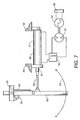
- FIGURE 7 there is shown an isolated side-elevational view of a rotor and stator of an arrangement. Electrical energy is generated in this arrangement by turning the rotor with respect to stator in the electrical energy converter 57.
- the rotor of the electrical energy converter 57 is moved by a motor means 3 3 that is driven by the motion of the pendulum 62.
- a link 64 is pivotally connected to the pendulum 62.
- An actuator 31 is pivotally connected to the link 64.
- the actuator 31 is a hydraulic actuator and has a piston 97 and cylinder 98.
- the piston 97 is pivotally connected to the link 64.
- the piston 97 moves in and out of the cylinder 98 as the pendulum 62 oscillates along path 63.
- Hydraulic fluid is pumped from the cylinder 98 to the hydraulic rectifier 32.
- the hydraulic rectifier 32 concentrates the mechanical energy of the actuator 31 and sends the mechanical energy 32 to the motor means 33.
- the motor means 33 is a hydraulic motor that is driven by hydraulic fluid from the hydraulic rectifier 32.
- the hydraulic motor 33 turns the rotor relative to the stator in the electrical energy converter 57. Electrical energy, i.e., electricity, is sent to the load 58.
- the pendulum 63 has a mounting assembly 61.
- the position sensor 60 is mounted to the mounting assembly 61 and senses the position the pendulum 62.
- the pendulum adjusting means 59 adjusts the position of the pendulum 62.
- FIGURE 8 there is shown an isolated side-elevational view of rotor and stator of a fourth embodiment of the present invention.
- the pendulum 71 is moved up and down by the pendulum adjusting means 68.
- the pendulum 71 is held within the mounting assembly 66.
- the pendulum adjusting means 68 adjusts the pendulum 71 up and down within the mounting assembly 66.
- Bearing 72 connects the mounting assembly 66 to the shell 65.
- the pendulum 71 imparts oscillatory motion upon the rod 70.
- the rod 70 oscillates a rotor in the electrical energy converter 67 relative to the stator located in the electrical energy converter 67.
- a rotation sensor 69 is located adjacent the bearings 72.
- the amplitude of the motion of the pendulum 71 is controlled by a caliper 27 and brake disk 28 arrangement. Free movement of the pendulum 71 is allowed by the calipers 27 when the calipers 27 do not touch the brake disk 28. If the amplitude of the pendulum 71 needs to be decreased, the calipers 27 press against the brake disk 28 so as to dampen the movement of the pendulum 71.
- FIGURE 9 there is shown a isolated side-elevational view of the fourth embodiment of the present invention, with a clutch 29.
- the clutch 29 allows the rod 70 to engage and disengage from the electrical energy converter 67.
- the brake 28 and calipers 27 operate similarly to those in FIGURE 8 .
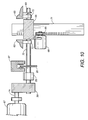
- FIGURE 10 there is shown an isolated side-elevational view of the fourth embodiment of the present invention, with a clutch 29 and gear box 30.
- the configuration in FIGURE 10 is similar to that of FIGURE 9 , except that a gear box 30 has been added.
- the pendulum 71 turns the rod 70, which turns gears in the gear box 30.
- a mechanical energy is imparted by the gear box 30 on axle 74 which turns a rotor relative to the stator in the electrical energy converter 67.
- the fourth embodiment of the present invention has a transmission with a clutch 29 and gear box 30.
- the brake system consisting of the caliper 27 and brake disk 28 dampens the movement of the pendulum 71.
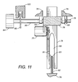
- FIGURE 11 there is shown an isolated side-elevational view of the rotor and stator of the fifth embodiment of the present invention.
- the pendulum 75 has a split 99 formed therein. Magnets 81 are placed on the walls of the split 99. Magnets 81 pass around the magnets of the variable inductance means 82.
- the variable inductance means 82 is connected to the shell 76.
- the pendulum 76 turns rod 80 which turns the rotor relative to the stator in the electrical energy converter 84.
- a caliber can dampen the motion of the brake disk 85 so as to control the motion of the pendulum 75.
- the pendulum adjusting means 77 adjusts the height of the pendulum 75.
- the pendulum adjusting means 77 is mounted to the mounting assembly 79.
- the bearings 83 are adjacent the mounting assembly 79. Rotation sensor 78 is placed adjacent the bearing 83.
- the bearings 83 are mounted to the shell 76.
- the rod 80 oscillates with the pendu
Description
- The present invention relates to the conversion of mechanical energy to electrical energy. More particularly, the present invention the relates to apparatus that convert energy provided by waves in a body of water into electricity. More particularly, the present invention relates to apparatuses utilizing magnetic induction.
- With rising oil prices, more and more efforts are being made to find alternative energy sources. Alternative energy sources include biomass (such as biodiesel), geothermal energy, solar energy, wind energy, and wave power. Wave power is a form of renewable energy. Therefore, wave power is a very desirable alternative to non-renewable sources, such as oil and coal. The apparatus that harness the energy of waves are commonly referred to as wave energy converters (WECs). The technology for wave power energy conversion is in the early stages in that much research and development is going into technology relating to the conversion of wave energy to electricity.
- A WEC is device that converts the mechanical energy of the waves of a body of water, such as the ocean, into electrical energy. The electrical energy is typically in the form of electricity. The obvious benefit of utilizing the motion of waves for the production of electrical energy is the abundance of ocean waves, the low cost of converting wave energy into electrical energy, extremely low emissions in such conversion, and very little environmental impact of devices that perform such a conversion.
- Many attempts to harness wave energy have yielded varying degrees of success. For example, several foreign companies have engineered and fielded new WEC concepts. Most of the companies involved in bringing these various concepts to market are located in Europe where mandates for sustainable renewable energy supplies follow the Kyoto Accord for reduction in carbon emissions. Several European nations are signatories to the Kyoto Accord and therefor have set forth various goals for implementing new power generating technologies, including onshore and offshore wind farms, WECs, and subsea turbine devices utilizing stable ocean and river currents. European nations lead the United States in the pursuit of alternative energies. For example, the Norwegian classification authority (Det Norske Veritas) has guidelines for the design and construction of WECs. Therefore, there is a need for the development of WECs in the United States.
- In order to fully maximize the use of wave power, a WEC must adapt to the prevailing wave environment. That is, the apparatus must adapt to the transient amplitude, frequency, and phase of the waves of a body of water. One problem associated with WECs is that to adapt to the transient nature of waves, the apparatus of the WEC must change a mass, stiffness or damping characteristic. Many WECs are not equipped to respond to the changes in waves. The ability of a WEC to respond to transient waves requires additional components and complexity, which further compounds the potential maintenance and reliability issues of a WEC.
- Another problem associated with current WECs is that the parts that convert wave energy to electrical energy are exposed directly to the environment. Therefore, these parts are subject to corrosion and disrepair. Thus, there is a need for a WEC that protects the energy-converting parts from the environment.
- Various patents have been issued relating to WECs. For example,
U.S. Patent No. 7,305,823, issued on December 11, 2007 to Stewart et al. , discloses a wave energy converter having two elements intended to be placed in a body of water. The two elements are able to move relative to each other in response to forces applied to the wave energy converter by the body of water. At least one of the two elements is a wave energy absorber. A mechanism is connected between the two elements so as to extract energy from the wave energy converter for producing output electric energy as a function of the movement between the two elements. Another mechanism is connected between a source of energy and one of the two elements. The mechanism senses and determines the displacement, velocity, and acceleration of one of the two elements relative to the other for selectively and actively supplying energy to one of the two elements so as to cause an increase in the displacement and velocity of one of the two elements relative to the other. -
U.S. Patent No. 6,291,904, issued on September 18, 2001 to Carroll , discloses an open-ended tube that is mounted in a fixed, vertical orientation within a body of water. The top and bottom ends of the tube are positioned at preselected depths relative to an average water level. The tube-top open end is disposed at a first depth approximately equal to, but not less than, the maximum preselected wave amplitude so that the top end is always submerged. The tube-bottom open end is disposed at a depth where the energy level associated with preselected waves of maximum wavelength is small. Water flows into and out of the tube in response to pressure variations caused by passing waves. A piston is disposed within the tube for converting the water flow to useful energy. -
U.S. Patent No. 7,352,073, issued on April 1, 2008 to Ames , discloses an ocean wave energy converter that has a generator with a rotating inner rotor surrounded by a counter-rotating outer rotor for generating electricity. A reciprocating drive rod drives the inner rotor on the downstroke of the drive rod and the outer rotor on the upstroke of the drive rod through a gear-driven driveshaft with clutches. A buoy is attached to an end of the drive rod whereby the undulation of the ocean waves relative to the buoy reciprocates the drive rod between the upstroke and the downstroke positions. -
U.S. Patent No. 7,298,054, issued on November 20, 2007 to Hirsch , discloses a wave energy conversion system that includes a base substantially connected to a wave-medium floor, a tidal platform connected to the base, and a tidal float connected to the tidal platform. An axle is connected to the tidal platform with an inductive coil positioned within the axle such that an axis of the inductive coil is parallel to the axle. A magnetic sleeve includes a magnetic sleeve opening such that the axle passes through the magnetic sleeve opening. A float member is connected to the magnetic sleeve. A moving wave causes displacement of the float member. The float member causes the magnetic sleeve to move relative to the inductive coil and to generate electrical energy within the inductive coil. -
U.S. Patent No. 5,512,795, issued on April 30, 1996 to Epstein et al. , discloses an electrical energy generator that has a cylindrical stator, a cylindrical liner of a piezoelectric material in concentric contact with the stator, and an armature rotatable about the liner. In one embodiment, as the armature rotates, the armature squeezes successive portions of the liner against the stator for alternately compressing and decompressing the liner portions for causing them to generate electrical energy. In another embodiment, the armature causes alternating stretching and destretching of successive portions of the liner between spaced-apart portions of the stator for causing the liner portions to generate electricity. -
U.S. Patent No. 4,748,338, issued on May 31, 1988 to Boyce , discloses an apparatus for extracting energy from the waves on a body of water that includes an assembly having a buoyancy sufficient for maintaining the assembly afloat in the water. The apparatus has a series of structures mounted on the assembly that have generally upwardly-oriented beams that have upper ends connected at least indirectly to one another. A pendulum drive shaft is suspended by a cable from the upper end of the beams. Each structure has a pulley at the upper ends of the beams through which a continuous loop of the cable passes so as to suspend the pendulum drive shaft and permit the pendulum drive shaft to rotate. A ratcheted pulley mounted at the lower end of each of the beams has a second continuous loop of cable passing therethrough. The second continuous loop of cable also loops around the pendulum drive shaft causing the pendulum drive shaft to rotate as it swings by rolling within the loop of the second cable which is anchored by the ratcheted pulley. The second cable is prevented from turning by the rachet during the forward swing of the pendulum. -
U.S. Patent No. 4,492,875, issued on January 8, 1985 to Rowe , discloses a buoy generator that has a hollow buoy having inner and outer surfaces, a winding mounted to the buoy parallel to the inner and outer surfaces, a magnetized member freely disposed in all dimensions within the hollow buoy for unrestricted rolling on the inside surface of the hollow buoy whenever the hollow buoy has any rolling movement, and a mechanism connected to an end of the windings for rectifying current flow therefrom. Upon mooring the buoy in the water, the flux lines of the magnetized roller cut the winding when there is water motion. Electrical current is provided by the winding to the rectifying mechanism. -
U.S. Patent No. 4,423,334, issued on December 27, 1983 to Jacobi et al. , discloses a wave motion powered electrical generator configured for installation in a buoy. The generator has an inverted pendulum with two windings formed at the free end thereof. The windings are aligned to articulate between two end stops. Each stop is provided with a magnetic circuit. As the loops thus pass through the magnetic circuit, electrical current is induced which may be rectified through a full-way rectifier to charge a battery. The buoy itself may be ballasted to have its fundamental resonance at more than double the wave frequency with the result that during each passing of a wave at least two induction cycles occur. -
U.S. Patent No. 4,352,023, issued on September 28, 1982 to Sachs et al. , discloses a mechanism for generating power from wave motion on a body of water. The mechanism includes a buoyant body which is adapted to float on a body of water and to roll and pitch in response to the wave motion of the water. A gyro-wave energy transducer is mounted on the buoyant body for translating the pendulum-like motions of the buoyant body into rotational motion. The gyro-wave energy transducer includes a gimbal that has first and second frames. The first frame is pivotally mounted to the second frame. The second frame is pivotally mounted to the buoyant body. A gyroscope is mounted to the first frame for rotation about an axis perpendicular to the axes of rotation of the first and second frames. A generator is coupled to the gyroscope for maintaining a controlled rotational velocity for the gyroscope. Transferring members are associated with one of the first and second frames for transferring torque of one of the first and second frames to the gyroscope. -
U.S. Patent No. 4,317,047, issued on February 23, 1982 to de Almada , discloses an apparatus for harnessing the energy derived from the undulatory motion of a body of water that includes an assembly having a buoyancy sufficient for maintaining it afloat in the water, a first structure substantially following multidirectional undulatory motions of the water, and a second structure mounted in the assembly for free movement in a plurality of planes with respect to the first structure. The second structure is displaceable by gravity and by forces derived from the motions of the first structure. A device is connected to the first and second structures for generating a pressure output in response to the force derived from the relative motions between the first and second structures. An arrangement is coupled to the pressure output of the device for utilizing, at least indirectly, the energy derived from the pressure output. -
U.S. Patent No. 4,266,143, issued on May 5, 1981 to Ng , discloses an energy conversion device which utilizes the natural movements of ocean waves to produce electrical energy. The apparatus is contained in a tank which is adapted to float near the surface of the water and tilt from side-to-side about a pivot point located below the tank, thereby simulating a pendulum-like movement. A sinker weight is employed to produce the appropriate movement of the tank and maintain the floating tank in balance at the ocean surface. The pendulum motion of the tank is used to roll gravity wheels in the tank in such manner that shafts associated with the gravity wheels are caused to rotate. Electrical generators are operatively connected to the rotating shafts for producing electrical energy from the mechanical rotational energy of the shafts as the tank tilts from side to side with the wave motion. -
U.S. Patent No. 4,260,901, issued on April 7, 1981 to Woodbridge , discloses a system for converting the mechanical energy in the wave motion of a body of water into electrical energy. A frame is fixed with respect to the wave motion of the water. A flotation element is buoyantly supported by the water and constrained to follow only the vertical component of the wave motion. The motion of the flotation element is transferred to an electrical generating device which includes a device for producing electromagnetic flux and electrical coils. The motion of the flotation element causes relative motion between the flux-producing device and the electrical coils thereby generating an electromotive force. A positioning subsystem is provided for moving the electrical generating device relative to the flotation element when the average depth of the body of water changes so as to maintain a symmetrical relative motion between the flux-producing device and the electrical coils. -
U.S. Patent No. 4,251,991, issued on February 24, 1981 to Wood , discloses an apparatus for generating power from the motion of a wave on a body of water that utilizes a spine formed by buoyant sections that are joined end-to-end and are ballasted so as to cause the sections to assume a predetermined position in calm water. Adjacent sections are joined in a manner enabling the sections to pivot more easily about at least one non-vertical axis when the sections are in the predetermined position. When the apparatus is subjected to wave motion the surge component of the wave motion is converted to vertical motion of the spine. Prime movers are mounted on the spine so as to rock relative to the spine under the heave component of wave motion, and under the vertical motion of the spine. The rocking motion of the prime movers is utilized to produce energy. -
U.S. Patent No. 4,110,630, issued on August 29, 1978 to Hendel , discloses a wave-powered electric generator. The generator includes a buoyant envelope tethered to a fixed point relative to the sea bottom. The buoyant envelope is water and air-tight. One or more stators and one or more elements moveable by the force of inertia are positioned within the stator. The buoyant envelope is a rectifier for rectifying the electric energy generated by the moveable element. A power transmission mechanism supplies the generated and rectified electric energy to a power station. In a preferred embodiment, a conductive fluid is employed as a moveable element. The fluid is passed through a concentrated magnetic field. -
U.S. Patent No. 3,696,251 issued on October 3, 1972 to Last et al. , discloses an electric generator for deriving electrical energy from oscillatory motion such as that of buoys, vehicles and animals. The generator has a stator and an armature coupled together by a spring mechanism. The coupling generates current when bodily movement of the generator causes, by inertia effects, relative movement of the armature and stator. - It is an object of the present invention to provide a wave energy converter that improves power generation.
- It is another object of the present invention to provide a wave energy converter that protects critical system components from direct contact with the ocean and its surrounding environment.
- It is another object of the present invention to provide a wave energy converter that reduces long term maintenance costs.
- It is still another object of the present invention to provide a wave energy converter that reduces inactivity due to adverse environmental conditions.
- It is another object of the present invention to provide a wave energy converter that utilizes a permanent magnet.
- It is still another object of the present invention to provide a wave energy converter that can be placed in any body of water having waves.
- It is another object of the present invention to provide a wave energy converter that utilizes magnetic induction to convert wave energy into electrical energy.
- It is still another object of the present invention to provide a wave energy converter that maximizes energy conversion for various wave frequencies.
- It is another object of the present invention to provide a wave energy converter that maximizes energy conversion for various wave sizes.
- It is another object of the present invention to provide a wave energy converter that varies inductive capacity.
- These and other objects and advantages of the present invention will become apparent from a reading of the attached specification and appended claims.
- The present invention is a wave energy converter comprising a shell, a pendulum pivotally positioned in the shell, a variable inductance means for varying an inductive capacity positioned in the shell, and a pendulum adjusting means for changing a position of a center of gravity of the pendulum. The pendulum has a magnet thereon. The variable inductance means has at least one wire coil. The magnet of the pendulum oscillates adjacent the wire coil. The wave energy converter further comprises a motion sensor positioned in the shell, a position sensor connected to the pendulum, a rotation sensor connected to the pendulum, and a controller connected to the motion sensor and to the position sensor and to the rotation sensor. The wave energy converter also has a conditioner means for conditioning an electrical energy produced by the variable inductance means. The conditioner means is connected to the variable inductance means.
- At least one battery can be connected to the controller, the motion sensor, the position sensor, the rotation sensor, and the pendulum adjusting means. A charger is connected to the battery. A solar panel is connected to the charger. A mounting assembly is positioned in the shell. The mounting assembly has at least one bearing connected to the pendulum. The magnet can be an electromagnet.
- In one embodiment, the pendulum comprises an elongate member, a shaft connected to the elongate member and positioned perpendicular to a longitudinal axis of the elongate member, and a disk is positioned on the shaft. The shaft is positioned perpendicular to a longitudinal axis of the elongate member. The shaft extends through a center of the disk. The magnet is positioned on the disk. The disk oscillates the magnet adjacent the wire coil.
- In another embodiment, the pendulum comprises an elongate member, a linkage pivotally connected to the elongate member, and a rod pivotally connected to the linkage. The magnet is positioned on the rod. The rod oscillates the magnet adjacent the wire coil. The shell is impermeable to moisture and contaminants.
- In an arrangement, a wave energy converter comprises a shell, a pendulum pivotally positioned in the shell, a link pivotally connected to the pendulum, an actuator having a piston and a cylinder, a hydraulic rectifier connected to the actuator, a motor connected to the hydraulic rectifier, a generator connected to the motor, and a pendulum adjusting means for changing a center of gravity of the pendulum. The pendulum has a magnet thereon. The piston is pivotally connected to the link. The motor is driven by a hydraulic fluid pumped by the actuator through the hydraulic rectifier. The motor turns the generator so as to produce electrical energy. The shell is impermeable to moisture and contaminants. The wave energy generator further comprises a motion sensor positioned in the shell, a position sensor connected to the pendulum, and a controller connected to the motion sensor. The controller activates the pendulum adjusting means upon receiving a signal from the motion sensor and a signal from the position sensor.
- In a further arrangement, an apparatus for converting a mechanical energy to an electrical energy comprises a shell receiving the mechanical energy, a pendulum pivotally positioned in the shell, a variable inductance means for varying an inductive capacity positioned in the shell, and a pendulum adjusting means for changing a center of gravity of the pendulum. The pendulum has a magnet. The shell transmits the mechanical energy to the pendulum so as to cause the pendulum to oscillate back-and-forth. The magnet of the pendulum oscillates adjacent the variable inductance means so as to generate the electrical energy. The apparatus further comprises a motion sensor positioned adjacent the shell, a position sensor connected to the pendulum, a rotation sensor connected to the pendulum, and a controller connected to the motion sensor and to the position sensor and to the rotation sensor. A conditioner means conditions the electrical energy produced by the variable inductance means. The conditioner means is connected to the variable inductance means. At least one battery is connected to the controller, the motion sensor, the position sensor, the rotation sensor, and the pendulum adjusting means. A charger is connected to the battery. A solar panel is connected to the charger. The shell is impermeable to moisture and contaminants.
- In still a further embodiment of the present invention, the pendulum comprises an elongate member, a shaft connected to the elongate member, and a disk positioned on the shaft. The shaft is positioned perpendicular to a longitudinal axis of the elongate member. The shaft extends through a center of the disk. The magnet is positioned on the disk. The disk oscillates the magnet adjacent the variable inductance means. The pendulum can also comprise an elongate member, a linkage pivotally connected to the elongate member, and a rod pivotally connected to the linkage. The magnet is positioned on the rod. The rod oscillates the magnet adjacent the variable inductance means.
-
-
FIGURE 1 shows a side elevational view of a preferred embodiment of the wave energy converter of the present invention. -
FIGURE 2 shows a cross-sectional view of the pendulum of the preferred embodiment of the present invention, taken along sight line 2-2 inFIGURE 1 . -
FIGURE 3 shows a side elevational view of the preferred embodiment of the wave energy converter of present invention, with batteries and a solar panel. -
FIGURE 4 shows an isolated side-elevational view of a second embodiment of the rotor and stator of the wave energy converter of the present invention. -
FIGURE 5 shows an isolated side-elevational view of a third embodiment of the rotor and stator of the wave energy converter of the present invention. -
FIGURE 6 shows a cross-sectional view of the rotor and stator of the third embodiment of the wave energy converter of the present invention, taken along sight line 6-6 inFIGURE 5 . -
FIGURE 7 shows an isolated side-elevational view of an arrangement of a rotor and stator of a wave energy converter. -
FIGURE 8 shows an isolated side-elevational view of a fourth embodiment of the rotor and stator of the wave energy converter of the present invention. -
FIGURE 9 shows a side-elevational view of the fourth embodiment, with a clutch attached thereto. -
FIGURE 10 shows a side-elevational view of the fourth embodiment, with a clutch and gear box attached thereto. -
FIGURE 11 shows an isolated side-elevational view of a fifth embodiment of the rotor and stator of the wave energy converter of the present invention. - Referring to
FIGURE 1 , there is shown a side-elevational view of the preferred embodiment of thewave energy converter 100 of the present invention. Thewave energy converter 100 has a shell 1, apendulum 15 pivotally positioned in the shell 1, and a variable inductance means 12 positioned in the shell 1. Thependulum 15 has amagnet 18 placed thereon. Thependulum 15 has a center ofgravity 16. Thependulum 15 oscillates about a longitudinal axis of arod 14. Therod 14 is connected to the shell 1 by bearings (not shown). The variable inductance means 12 shown inFIGURE 1 has wire coils 20. Themagnet 18 of thependulum 15 oscillates adjacent the wire coils 20 so as to produce electricity through electromagnetic induction. The variable inductance means 12 can vary the inductive capacity of thewave energy converter 100. That is, the variable inductance means 12 can increase or decrease selectively the number of wire coils 20 that are active so as to generate more or less electricity by electromagnetic induction. The wire coils 19 of the variable inductance means 12 are similar to the stator of a typical generator. Themagnet 18 of thependulum 15 is similar to the rotor of a typical generator. The path of theoscillating magnet 18 is shown by double-arrowedline 19. - In the present invention, a mechanical energy, such as a wave 2, is imparted upon the shell 1. Because the
pendulum 15 is connected to the shell 1, any energy imparted onto the shell 1 is transferred to thependulum 15. Although mechanical energy can be exerted upon the shell 1 in any three-dimensional direction, for the purpose of mathematical simplicity, only the applied horizontal motion of the wave 2 against the shell 1 demonstrates the efficiency of thewave energy converter 100 of the present invention. The following equation is the basic differential equation of motion for apendulum 15 that is acted upon by an external force at its pivot along with a damping force:
pendulum 15. The symbol "c" is the damping coefficient. The symbol "m" is the mass of thependulum 15. The symbol "g" is the gravitational constant. The symbol "d" is the distance between the center ofgravity 16 of thependulum 15 and thepivot axis 14 of thependulum 15. The symbol "x"" is the acceleration of thependulum 15 as a function of the mechanical energy, i.e. wave, acting upon thewave energy converter 100. For simplicity purposes, x" and θ are considered sinusoidal-varying functions expressed in terms of a single circular frequency, ω, and time, t. Applying the sinusoidal functions and rewriting the equation produces the following equation:
- Thus, the
pendulum 15 of the present invention has a pendulum adjust means 9 that adjusts the distance between the center ofgravity 16 of thependulum 15 and thepivot axis 14 of thependulum 15. The pendulum adjusting means 9 move the pendulum up and down relative to the mountingassembly 13 so as to change the distance of the center ofgravity 16 and thepivot axis 14. A greater distance between center ofgravity 14 and thepivot axis 14 of thependulum 15 causes thependulum 15 to oscillate more slowly. A small distance between the center ofgravity 16 and thepivot axis 14 of thependulum 15 causes thependulum 15 to oscillate more quickly. Thus, if wave 2 has a high frequency of recurrence, the pendulum adjusting means 9 adjusts the distance between the center ofgravity 16 and thepivot axis 14 so that the pendulum will swing quicker so as to achieve a harmonic resonance with the frequency of the wave 2 and thus optimize the amount of electricity generated between themagnet 18 and the wire coils 19 of the variable inductance means 12. If the frequency of the wave 2 is low, then the pendulum adjusting means 9 increases the distance between the center ofgravity 16 and thepivot axis 14 so that thependulum 15 swings, or oscillates, more slowly so as to match the harmonic resonance of the waves 2 and optimize the generation of electricity between themagnet 18 and the wire coils 20. - The circular natural frequency of the pendulum is expressed as a function of the distance between the center of
gravity 16 of thependulum 15 and thepivot axis 14 of thependulum 15 by the following equation:
gravity 16 of thependulum 15 and thepivot axis 14 of thependulum 15. The symbol "L" is the length of thependulum 15, which is constant because the length of thependulum 15 is always the same. "ω" and "g" were defined above. - The above equation is used by a controller 7 positioned in the shell 1. A
motion sensor 6 is positioned in the shell 1 senses the frequency of the wave 2. This frequency is then used in the above equation as the circular natural frequency of thependulum 15, and the controller 7 then calculates the distance d that is needed between the center ofgravity 16 of thependulum 15 and thepivot axis 14 of thependulum 15 so as to have thependulum 15 match the frequency of the wave 2. Manipulation of the symbol "d" effects both the inertial and gravitational terms of the second equation above. Once the controller 7 knows the distance needed for thependulum 15, the pendulum adjusting means 9 is activated by the controller 7 so as to change the distance between the center ofgravity 16 and thepivot axis 14. Theposition sensor 10 communicates the position ofpendulum 15 to the controller 7. - The damping term, cΘω, of second equation is a mathematical expression for the rate of energy removal from the
WEC 100. Varying this term controls the rate at which energy is converted from mechanical energy to electrical energy. The rate as which energy is converted from mechanical energy to electrical energy in theWEC 100 of the present invention can be varied by controlling the amplitude of the motion of thependulum 15 alongpath 19. The amplitude of thependulum 15 can be controlled with a brake disk and caliper operatively connected to thepivot axis 14 of thependulum 15. Controlling the amplitude of the motion of thependulum 15 allows thewave energy converter 100 to be designed to operate over a defined range of motion which is useful in determining the overall dimensions of thependulum 15. - Referring still to
FIGURE 1 , themagnet 18 is located onpendulum 15 so that themagnet 18 passes adjacent the wire coils 20. Electricity is generated by the oscillation of themagnet 18 past the wire coils 20 by magnetic or electromagnetic induction. Induction occurs when a magnetic field moves relative to a conductor. In the present invention, the magnetic field is provided by themagnet 18. The conductor is the wire coils 20 of the variable inductance means 12. Themagnet 18 is also referred to as the rotor. The wire coils 20 are also referred to as thestator 20. If thependulum 15 is still, then themagnet 18 does not move and no induction occurs. Thus, it is important for themagnet 18 to oscillate as much as possible so as to generate maximum amount of electricity. The point at which themagnet 18 and wire coils 20 generate the maximum amount of electricity is when the frequency of thependulum 15 is in harmonic resonance with the frequency of the waves 2. The configurations of thependulum 15, the pendulum adjusting means 9, the controller 7, andposition sensor 10 allow thewave energy converter 100 of the present invention to maximize the electricity generated by achieving a harmonic frequency for any given wave 2. The electrical energy generated in the wire coils 20 of the variable inductance means 12 is conditioned in the conditioner means 8 and then sent as electricity for use by aload 5, such as a typical electrical power grid. Electricity can travel to and from thewave energy converter 100 by way of the connection between the conditioner means 8 and theload 5. Thus, any electrical energy needed by the components of thewave energy converter 100, such as the controller 7, can be provided by theload 5 if thependulum 15 and wire coils 20 are not generating enough electrical energy. The controller 7 is connected to the variable inductance means 12 so as to control the inductive capacity of the variable inductance means 12. - Referring to
FIGURE 2 , there is shown a cross-sectional view of thependulum 15 of thewave energy converter 100 of the present invention, taken along sight line 2-2 ofFIGURE 1 . Thependulum 15 moves up and down through the mountingassembly 13 by the motion of the pendulum adjusting means 9. The pendulum adjusting means 9 has acog wheel 87 that is rotated by amotor 91. Themotor 91 is activated by the controller (not shown).Teeth 86 are formed in the side of thependulum 15 so as to operatively cooperate with thecog wheel 87 of the pendulum adjusting means 9. Although the embodiment of the pendulum adjusting means 9 shown inFIGURE 1 includes amotor 91,cog wheel 87, andteeth 86, the pendulum adjusting means 9 can include any mechanism suitable for moving thependulum 15 up and down such as a lever assembly, a hydraulic assembly, a magnetic assembly, an electrical assembly, or any other assembly. Theposition sensor 10 communicates with the controller (not shown) regarding the distance between the center ofgravity 16 and the pivot axis of thependulum 15. As thependulum 15 moves up and down, therod 88 of theposition sensor 10 moves into and out of thehousing 89 of theposition sensor 10. The rod is secured to thependulum 15 byanchor 90. Thehousing 89 is secured to the mountingassembly 13. Theposition sensor 10 sends a signal to the controller concerning the height of thependulum 15 that is determined by the extent to which therod 88 extends from thehousing 89 of theposition sensor 10. - Referring to
FIGURE 3 , there is shown a side elevational view of the preferred embodiment of thewave energy converter 100 of present invention, withbatteries 22 and asolar panel 24. Thebatteries 22 provide electrical energy for components of thewave energy converter 100, such as the controller 7 and the pendulum adjusting means 9. Thebatteries 22 can be charged bycharger 23. The charger receives electrical energy so as to charge thebatteries 22. Electrical energy for thecharger 23 can be provided by thesolar panel 24 or by theload 5. Thesolar panel 24 can be mounted to the shell 1 of thewave energy converter 100. The arrangement of thewave energy converter 100 inFIGURE 3 is the same as that inFIGURE 1 , except that abattery 22, acharger 23, andsolar panel 24 have been added to thewave energy converter 100. Thesolar panel 24 can be a photovoltaic cell. - Referring to
FIGURE 4 , there is shown an isolated side-elevational view of the rotor and stator a second embodiment of the present invention. The rotor is thependulum 39 withmagnets 40 thereon. Thependulum 39 has anelongate member 101, alinkage 43 pivotally connected to theelongate member 101, and arod 91 pivotally connected to thelinkage 43. Thelinkage 43 is pivotally connected to thependulum 39 and to therod 91. A number ofmagnets 40 are placed on therod 91. As theelongate member 101 of thependulum 39 swings alongpath 41, therod 91 moves horizontally through mounts 92. Themounts 92 are attached to theshell 34. Thus, as waves or mechanical energy hit theshell 34, thependulum 39 oscillates alongpath 41 so as to move themagnets 40 onrod 91 horizontally through the wire coils 42 of the variable inductance means 37. The distance between the center of gravity and the pivot axis of thependulum 39 is adjusted by the communications among the pendulum adjusting means 35, theposition sensor 36, and the controller (not shown). The stator of the second embodiment is the wire coils 42 of the variable inductance means 37. - Referring to
FIGURE 5 , there is shown an isolated cross-sectional of the rotor and stator of a third embodiment of the present invention. The rotor is thependulum 51. Thependulum 51 has anelongate member 102, ashaft 93, anddisks 55 havingmagnets 52 thereon. Theshaft 93 is connected to theelongate member 102. Theshaft 93 is perpendicular to a longitudinal axis of theelongate member 102. Thedisks 55 and theirrespective magnets 52 rotate through wire coils 53 of the variable inductance means 49 as thependulum 51 oscillates. That is, as theelongate member 102 oscillates theshaft 93, theshaft 93 oscillates thedisks 55. Thedisks 55 have a small thickness, and themagnets 52 rotate between wire coils 53. The stator of the third embodiment is the wire coils 53 of the variable inductance means 49. The electrical energy generated by the variable inductance means 49 is sent to the conditioner means 46 where electricity is conditioned for transmission to theload 45. Thependulum 51 is connected to thehousing 44 by the mountingassembly 50. The mountingassembly 50 hasbearings 54 that allow for easy oscillation of thependulum 51 within theshell 44. The pendulum adjusting means 47 is mounted to the mountingassembly 50. The pendulum adjusting means 47 has amotor 94 that drives acog wheel 95. Themotor 94 is mounted to the mountingassembly 50. Thecog wheel 95 engages theteeth 96 formed in the side of thependulum 51. Themotor 94 rotates thecog wheel 95 so as to raise thependulum 51 up and down. The bearing 54 of the mountingassembly 50 can be a bushing. Arotation sensor 48 is placed adjacent the mountingassembly 50. Therotation sensor 48 measures the angular position and the angular velocity of thependulum 51. - Referring to
FIGURE 6 , there is shown a cross-sectional view of thedisk 55 andwire coil 53, taken along site line 6-6 ofFIGURE 5 . Thedisk 55 is mounted on theshaft 93. Theshaft 93 extends through a center of thedisk 55.Magnets 52 are positioned on the periphery of thedisk 55. Themagnets 52 oscillate past the wire coils 53 as thependulum 51 oscillates. Thependulum 51 turns theshaft 93 which turns thedisk 55. Thus, thedisk 55 causes the magnet fields provided by themagnets 52 to move relative to thecoils 53. - Referring to
FIGURE 7 , there is shown an isolated side-elevational view of a rotor and stator of an arrangement. Electrical energy is generated in this arrangement by turning the rotor with respect to stator in theelectrical energy converter 57. The rotor of theelectrical energy converter 57 is moved by a motor means 3 3 that is driven by the motion of thependulum 62. As a wave imparts mechanical energy on the shell of the wave energy converter, thependulum 62 oscillates alongpath 63. Alink 64 is pivotally connected to thependulum 62. Anactuator 31 is pivotally connected to thelink 64. Theactuator 31 is a hydraulic actuator and has apiston 97 andcylinder 98. Thepiston 97 is pivotally connected to thelink 64. Thepiston 97 moves in and out of thecylinder 98 as thependulum 62 oscillates alongpath 63. Hydraulic fluid is pumped from thecylinder 98 to thehydraulic rectifier 32. Thehydraulic rectifier 32 concentrates the mechanical energy of theactuator 31 and sends themechanical energy 32 to the motor means 33. In this embodiment, the motor means 33 is a hydraulic motor that is driven by hydraulic fluid from thehydraulic rectifier 32. Thehydraulic motor 33 turns the rotor relative to the stator in theelectrical energy converter 57. Electrical energy, i.e., electricity, is sent to theload 58. Thependulum 63 has a mountingassembly 61. Theposition sensor 60 is mounted to the mountingassembly 61 and senses the position thependulum 62. The pendulum adjusting means 59 adjusts the position of thependulum 62. - Referring to
FIGURE 8 , there is shown an isolated side-elevational view of rotor and stator of a fourth embodiment of the present invention. Thependulum 71 is moved up and down by the pendulum adjusting means 68. Thependulum 71 is held within the mountingassembly 66. The pendulum adjusting means 68 adjusts thependulum 71 up and down within the mountingassembly 66.Bearing 72 connects the mountingassembly 66 to theshell 65. Thependulum 71 imparts oscillatory motion upon therod 70. Therod 70 oscillates a rotor in theelectrical energy converter 67 relative to the stator located in theelectrical energy converter 67. Arotation sensor 69 is located adjacent thebearings 72. The amplitude of the motion of thependulum 71 is controlled by acaliper 27 andbrake disk 28 arrangement. Free movement of thependulum 71 is allowed by thecalipers 27 when thecalipers 27 do not touch thebrake disk 28. If the amplitude of thependulum 71 needs to be decreased, thecalipers 27 press against thebrake disk 28 so as to dampen the movement of thependulum 71. - Referring to
FIGURE 9 , there is shown a isolated side-elevational view of the fourth embodiment of the present invention, with a clutch 29. The clutch 29 allows therod 70 to engage and disengage from theelectrical energy converter 67. Thebrake 28 andcalipers 27 operate similarly to those inFIGURE 8 . - Referring to
FIGURE 10 , there is shown an isolated side-elevational view of the fourth embodiment of the present invention, with a clutch 29 andgear box 30. The configuration inFIGURE 10 is similar to that ofFIGURE 9 , except that agear box 30 has been added. Thependulum 71 turns therod 70, which turns gears in thegear box 30. A mechanical energy is imparted by thegear box 30 onaxle 74 which turns a rotor relative to the stator in theelectrical energy converter 67. Thus, the fourth embodiment of the present invention has a transmission with a clutch 29 andgear box 30. The brake system consisting of thecaliper 27 andbrake disk 28 dampens the movement of thependulum 71. - Referring to
FIGURE 11 , there is shown an isolated side-elevational view of the rotor and stator of the fifth embodiment of the present invention. Thependulum 75 has asplit 99 formed therein.Magnets 81 are placed on the walls of thesplit 99.Magnets 81 pass around the magnets of the variable inductance means 82. The variable inductance means 82 is connected to theshell 76. Thependulum 76 turnsrod 80 which turns the rotor relative to the stator in theelectrical energy converter 84. A caliber can dampen the motion of thebrake disk 85 so as to control the motion of thependulum 75. The pendulum adjusting means 77 adjusts the height of thependulum 75. The pendulum adjusting means 77 is mounted to the mountingassembly 79. Thebearings 83 are adjacent the mountingassembly 79.Rotation sensor 78 is placed adjacent thebearing 83. Thebearings 83 are mounted to theshell 76. Therod 80 oscillates with thependulum 75 within thebearings 83.
Claims (11)
- A wave energy converter (100) comprising:a shell (1)a pendulum (15) pivotally positioned in said shell (1), said pendulum (15) having a magnet (18) thereon;characterized by the provision ofa variable inductance means (12) for varying an inductive capacity, said variable inductance means (12) being positioned in said shell (1), said variable inductance means (12) having at least one wire coil (20), said magnet (18) of said pendulum (15) oscillating relative to the wire coil (20); anda pendulum adjusting means (9) operatively connected to said pendulum for changing a center of gravity (16) of said pendulum.
- The wave energy converter of Claim 1, further comprising:a motion sensor positioned in said shell;a position sensor connected to said pendulum;a rotation sensor connected to said pendulum; anda controller connected to said motion sensor and said position sensor and said rotation sensor.
- The wave energy converter of Claim 2, further comprising:a conditioner means for conditioning an electrical energy produced by said variable inductance means, said conditioner means being connected to said variable inductance means.
- The wave energy converter of Claim 3, further comprising:a rod connected to said pendulum along a pivot axis of said pendulum;a brake disk mounted on said rod; anda caliper mounted on said brake disk, said caliper pressing against said brake disk so as to dampen a motion of said disk and said rod and said pendulum.
- The wave energy converter of Claim 2, further comprising:at least one battery connected to said controller and to said motion sensor and to said position sensor and to said rotation sensor and to said pendulum adjusting means;a charger connected to the battery; anda solar panel connected to said charger.
- The wave energy converter of Claim 1, said magnet being an electromagnet.
- The wave energy converter of Claim 1, further comprising:a mounting assembly positioned in said shell, said mounting assembly having at least one bearing connected to said pendulum.
- The wave energy converter of Claim 7, said pendulum adjusting means comprising:a motor mounted to said mounting assembly;a cog wheel rotatably connected to said motor; anda plurality of teeth formed on a side of said pendulum, said cog wheel suitable for engaging said plurality of teeth.
- The wave energy converter of Claim 1, said pendulum comprising:an elongate member;a shaft connected to said elongate member, said shaft extending transverse to a longitudinal axis of said elongate member; anda disk positioned on said shaft, said magnet being positioned on said disk.
- The wave energy converter of Claim 1, said pendulum comprising:an elongate member;a linkage pivotally connected to said elongate member; anda rod pivotally connected to said linkage, said magnet being positioned on said rod.
- The wave energy converter of Claim 1, said shell being impermeable to moisture.
Applications Claiming Priority (2)
| Application Number | Priority Date | Filing Date | Title |
|---|---|---|---|
| US12/271,743 US8026620B2 (en) | 2008-11-14 | 2008-11-14 | Wave energy converter |
| PCT/US2009/064335 WO2010056956A2 (en) | 2008-11-14 | 2009-11-13 | Wave energy converter |
Publications (3)
| Publication Number | Publication Date |
|---|---|
| EP2356332A2 EP2356332A2 (en) | 2011-08-17 |
| EP2356332A4 EP2356332A4 (en) | 2013-07-03 |
| EP2356332B1 true EP2356332B1 (en) | 2015-03-18 |
Family
ID=42170720
Family Applications (1)
| Application Number | Title | Priority Date | Filing Date |
|---|---|---|---|
| EP09826812.1A Not-in-force EP2356332B1 (en) | 2008-11-14 | 2009-11-13 | Wave energy converter |
Country Status (3)
| Country | Link |
|---|---|
| US (2) | US8026620B2 (en) |
| EP (1) | EP2356332B1 (en) |
| WO (1) | WO2010056956A2 (en) |
Families Citing this family (62)
| Publication number | Priority date | Publication date | Assignee | Title |
|---|---|---|---|---|
| FR2876751B1 (en) | 2004-10-15 | 2007-01-19 | Centre Nat Rech Scient Cnrse | APPARATUS FOR CONVERTING WAVE ENERGY INTO ELECTRICAL ENERGY |
| US8519557B2 (en) * | 2005-11-07 | 2013-08-27 | Gwave Llc | System for producing energy through the action of waves |
| US9976535B2 (en) | 2005-11-07 | 2018-05-22 | Gwave Llc | System for producing energy through the action of waves |
| US7737569B2 (en) * | 2006-10-24 | 2010-06-15 | Seadyne Energy Systems, Llc | System and method for converting ocean wave energy into electricity |
| US7453165B2 (en) * | 2006-10-24 | 2008-11-18 | Seadyne Energy Systems, Llc | Method and apparatus for converting ocean wave energy into electricity |
| US20090179432A1 (en) * | 2007-01-23 | 2009-07-16 | Scott Wattenbarger | Gravitational magnetic energy converter |
| US8334605B2 (en) * | 2007-07-20 | 2012-12-18 | Vito Antonio Catinella | Floating mechanical structure to produce directly electricity by means of the swinging of a magnetic pendulum caused by sea wave motion |
| US20150054285A1 (en) * | 2008-11-14 | 2015-02-26 | Miles HOBDY | Wave energy converter |
| US20100213774A1 (en) * | 2009-02-20 | 2010-08-26 | Ezra Shimshi | Machines of imbalanced and gravitating magnetic bases |
| US8373296B1 (en) * | 2009-06-22 | 2013-02-12 | James Walter Weber | Integrated lunar tide electric generator and floating retail structures system |
| US8198745B2 (en) * | 2009-08-20 | 2012-06-12 | Huntington Ingalls Incorporated | Tuned rolling wave energy extractor |
| US8692523B2 (en) * | 2009-11-04 | 2014-04-08 | General Electric Company | Power generation system and method with voltage fault ride-through capability |
| AT509918B1 (en) * | 2010-06-07 | 2013-09-15 | Eichhorn Karl | DEVICE FOR CONVERTING KINETIC ENERGY TO ELECTRICAL ENERGY |
| TWI468901B (en) * | 2010-07-28 | 2015-01-11 | Chi Mei Comm Systems Inc | A mobile electronic device |
| US8604649B1 (en) * | 2010-08-14 | 2013-12-10 | Robert J. Bartol, Jr. | Electric generator and related methods |
| GB2484324A (en) * | 2010-10-07 | 2012-04-11 | Adnan Mansoor | Power generating apparatus for a vessel, eg a ship or boat |
| EP2469072B1 (en) * | 2010-12-27 | 2015-04-15 | Openhydro IP Limited | A hydroelectric turbine and method of braking the hydroelectric turbine |
| US20120198829A1 (en) * | 2011-02-04 | 2012-08-09 | Francois Gagnon | Energy management system using hydraulic compensator for the production of electricity from one or several networks of cynetic energy sources |
| US9222465B2 (en) * | 2011-04-15 | 2015-12-29 | Northeastern University | Non-rotating wind energy generator |
| CN103843237B (en) * | 2011-07-28 | 2017-08-04 | 国立大学法人冈山大学 | Generator |
| DE102011084407A1 (en) * | 2011-10-13 | 2013-04-18 | Zf Friedrichshafen Ag | Switching module for a switch, switch, method for indicating actuation of a switch and method for controlling a device |
| US9273663B2 (en) * | 2012-01-23 | 2016-03-01 | Wright's Well Control Services, Llc | Subsea power source, methods, and systems |
| EP2817877A4 (en) * | 2012-02-22 | 2016-01-27 | Int Electronic Machines Corp | Energy harvesting |
| CN102642453A (en) * | 2012-04-18 | 2012-08-22 | 杨亦勇 | Method for applying frequency resonance in electromobile kinetic energy power generation |
| PE20150225A1 (en) | 2012-06-04 | 2015-02-22 | Gwave Llc | ENERGY PRODUCTION SYSTEM THROUGH THE ACTION OF WAVES |
| CN102734103A (en) * | 2012-06-08 | 2012-10-17 | 杨长易 | Heavy-pendulum-type intelligent automatic power station |
| WO2014063223A1 (en) | 2012-10-26 | 2014-05-01 | Sullivan William Paul | System and apparatus for generating electricity from motion of fluid |
| ES2727662T3 (en) * | 2012-10-30 | 2019-10-17 | Jain Irrigation Systems Ltd | Motion control system and procedure with obtaining energy |
| US8734084B1 (en) * | 2012-12-17 | 2014-05-27 | Andrew Lovas | Wind wing |
| US9322387B2 (en) * | 2013-03-15 | 2016-04-26 | Neptune Wave Power Llc | Maximizing output of a generator operating under the influence of wave motion by applying an optimum restoring force |
| IL225336A (en) * | 2013-03-19 | 2015-11-30 | Oren Mordechai Gertel | Ornithopter engine |
| US9121394B2 (en) * | 2013-04-04 | 2015-09-01 | Metso Minerals Industries, Inc. | Energy harvester for converting vibrational motion of a vibrating equipment into electrical energy, and a device for monitoring the operation of a vibrating equipment |
| CN103647430A (en) * | 2013-12-13 | 2014-03-19 | 叶卫列 | Swing type power generating device and system thereof |
| ES2950289T3 (en) | 2013-12-18 | 2023-10-06 | Ingeteam Power Tech Sa | Variable impedance device for a wind turbine |
| US10060559B2 (en) | 2014-01-20 | 2018-08-28 | Mitchell Fait | Underwater utility line |
| WO2015157528A1 (en) | 2014-04-09 | 2015-10-15 | Brimes Energy Inc. | Wave energy conversion system |
| WO2015177804A1 (en) * | 2014-05-19 | 2015-11-26 | Ramesh Rajagopal | A leverage assembly for energy generation |
| US9825516B2 (en) * | 2014-08-20 | 2017-11-21 | Andrew Lovas | Windraider |
| WO2016064890A1 (en) * | 2014-10-20 | 2016-04-28 | Fait Mitchell | A buoy for obtaining energy from a wave in a body of water |
| US9570969B1 (en) * | 2014-11-19 | 2017-02-14 | Theodore R. Bristow, Jr. | Electrical generator |
| SG11201708101PA (en) * | 2015-06-05 | 2017-10-30 | Univ Nanyang Tech | Wave energy converter |
| JP6622023B2 (en) * | 2015-07-30 | 2019-12-18 | 株式会社アサヒテクノ | Wave power generator |
| US9780624B2 (en) * | 2015-09-04 | 2017-10-03 | Xiao Liang Li | Assembly for harnessing a pendulum motion from fluid wave energy for conversion to power |
| CN105508129B (en) * | 2015-12-23 | 2019-04-26 | 浙江海洋学院 | A kind of Wave-activated power generation equipment |
| AU2017331811A1 (en) * | 2016-09-23 | 2019-04-11 | Amog Technologies Pty Ltd | Wave energy converter |
| US20180119679A1 (en) * | 2016-10-07 | 2018-05-03 | Kun-Tien Wu | Oscillating pendulum-based power generation mechanism of a power generator |
| US20180102691A1 (en) * | 2016-10-07 | 2018-04-12 | Kun-Tien Wu | Oscillating pendulum-based power generation mechanism of a power generator |
| CL2016002672A1 (en) * | 2016-10-20 | 2017-04-28 | Univ Pontificia Catolica Chile | Device and method of energy extraction, for obtaining electrical energy from mechanical vibrations, which maximizes energy extraction. |
| WO2018147880A1 (en) * | 2017-02-13 | 2018-08-16 | Bristow Theodore R Jr | Electrical generator |
| US11719219B2 (en) * | 2017-06-08 | 2023-08-08 | P Tech, Llc | Systems and methods for energy harvest |
| CN107559134B (en) * | 2017-08-22 | 2019-11-08 | 哈尔滨工程大学 | A kind of ship wave wave energy generating set |
| DK179738B1 (en) | 2017-10-11 | 2019-04-30 | Ravn Niels | Wind-Driven Energy Converting Device |
| US11412587B2 (en) * | 2018-10-20 | 2022-08-09 | Mark Biasotti | Animated firefly novelty device |
| US10352288B1 (en) * | 2019-01-23 | 2019-07-16 | Saad KH. S. M. E. Alsahlawi | Ocean wave energy generator and parabolic concentrator system |
| CN110311607B (en) * | 2019-07-24 | 2021-01-22 | 大连海事大学 | Maximum wave energy capturing method for backstepping sliding mode |
| US11637479B2 (en) | 2019-12-30 | 2023-04-25 | P Tech, Llc | Wave energy harvester |
| CN112648160B (en) * | 2020-12-24 | 2022-05-20 | 湖南工程学院 | Modulation bistable pendulum power generation backpack |
| WO2022164354A1 (en) * | 2021-01-31 | 2022-08-04 | Al Ghamedi Mubarak Manahi | Future energy |
| CN114268191B (en) * | 2021-12-15 | 2023-02-28 | 浙江大学 | Double-shaft multistable wave vibration energy collecting device |
| KR20230096203A (en) * | 2021-12-22 | 2023-06-30 | 현대자동차주식회사 | Renewable Energy Generation Device And Control Method Therefor |
| TWI814220B (en) * | 2022-01-24 | 2023-09-01 | 崑山科技大學 | Swinging power generating device |
| GB2617812A (en) * | 2022-02-04 | 2023-10-25 | Andrew Karim Arif | Repelling magnetic instrument |
Family Cites Families (11)
| Publication number | Priority date | Publication date | Assignee | Title |
|---|---|---|---|---|
| US1399558A (en) * | 1919-01-09 | 1921-12-06 | Olaf L Howe | Water-motor |
| US1925742A (en) * | 1932-04-21 | 1933-09-05 | Robert F Bamber | Wave motor |
| US3912938A (en) * | 1974-01-25 | 1975-10-14 | Gregory D Filipenco | Electrical stations operated by waves |
| US4423334A (en) * | 1979-09-28 | 1983-12-27 | Jacobi Edgar F | Wave motion electric generator |
| JPS6158977A (en) * | 1984-08-30 | 1986-03-26 | Muroran Kogyo Daigaku | Method of generating electrical power with use of wave force and device therefor |
| JP3218462B2 (en) * | 1998-11-17 | 2001-10-15 | 富治 渡部 | Wave energy conversion device |
| JP2003206845A (en) * | 2002-01-15 | 2003-07-25 | Kajima Corp | Wave force energy converter |
| GB0408496D0 (en) * | 2004-04-16 | 2004-05-19 | Willis James D | Electric pulse pendulum power generator |
| FR2876751B1 (en) * | 2004-10-15 | 2007-01-19 | Centre Nat Rech Scient Cnrse | APPARATUS FOR CONVERTING WAVE ENERGY INTO ELECTRICAL ENERGY |
| JP4613649B2 (en) * | 2005-02-16 | 2011-01-19 | 哲彦 藤里 | Gravitational wave power generator |
| US7629700B2 (en) * | 2006-10-05 | 2009-12-08 | Marshall University Research Corp. | Motion induced electrical generator for charging and operating devices |
-
2008
- 2008-11-14 US US12/271,743 patent/US8026620B2/en not_active Expired - Fee Related
-
2009
- 2009-11-13 WO PCT/US2009/064335 patent/WO2010056956A2/en active Application Filing
- 2009-11-13 EP EP09826812.1A patent/EP2356332B1/en not_active Not-in-force
-
2011
- 2011-07-29 US US13/193,973 patent/US8102065B2/en not_active Expired - Fee Related
Also Published As
| Publication number | Publication date |
|---|---|
| WO2010056956A2 (en) | 2010-05-20 |
| US20110285128A1 (en) | 2011-11-24 |
| US8026620B2 (en) | 2011-09-27 |
| EP2356332A4 (en) | 2013-07-03 |
| WO2010056956A3 (en) | 2010-07-29 |
| US20100123313A1 (en) | 2010-05-20 |
| EP2356332A2 (en) | 2011-08-17 |
| US8102065B2 (en) | 2012-01-24 |
Similar Documents
| Publication | Publication Date | Title |
|---|---|---|
| EP2356332B1 (en) | Wave energy converter | |
| US8907513B2 (en) | Wave energy converter | |
| US8836152B2 (en) | Hydraulic wave energy converter with variable damping | |
| US20150054285A1 (en) | Wave energy converter | |
| JP5497781B2 (en) | A system that generates energy through the movement of waves | |
| US7215036B1 (en) | Current power generator | |
| US7319278B2 (en) | Ocean wave generation | |
| US8134281B2 (en) | Electrical generators for use in unmoored buoys and the like platforms with low-frequency and time-varying oscillatory motions | |
| JP2013532801A (en) | A system that generates energy through wave motion | |
| US20200018281A1 (en) | Wave energy converter | |
| US20100025999A1 (en) | Ocean wave electricity generation | |
| US20110185719A1 (en) | System for Producing Energy Through the Action of Waves | |
| CN104100444A (en) | Marine vehicle utilizing wave energy | |
| KR20160074512A (en) | Energy production device and system | |
| CN211082122U (en) | Compound pendulum frequency-raising type wave energy collecting device | |
| WO2012131705A2 (en) | A device for generating electrical energy using ocean waves | |
| Chandrasekaran et al. | DEEP OCEAN WAVE ENERGY SYSTEMS: EXPERIMENTAL INVESTIGATIONS. | |
| CN114268191A (en) | Double-shaft multistable wave vibration energy collecting device | |
| WO2021248224A1 (en) | System and method for lift assisted magnetic power | |
| JP2022551226A (en) | Wave energy absorption converter and power generation system | |
| US20040103658A1 (en) | Fluid wave electric generator system | |
| KR20100126866A (en) | Wave-force power generation equipment for steel slabs a sticking of electromagnetic induction power generation | |
| RU2802901C1 (en) | Wave power plant with pendulum electric generator | |
| KR101960705B1 (en) | A wave energy converter with variable stiffness | |
| KR20090068311A (en) | Wave power generation equipment |
Legal Events
| Date | Code | Title | Description |
|---|---|---|---|
| PUAI | Public reference made under article 153(3) epc to a published international application that has entered the european phase |
Free format text: ORIGINAL CODE: 0009012 |
|
| 17P | Request for examination filed |
Effective date: 20110608 |
|
| AK | Designated contracting states |
Kind code of ref document: A2 Designated state(s): AT BE BG CH CY CZ DE DK EE ES FI FR GB GR HR HU IE IS IT LI LT LU LV MC MK MT NL NO PL PT RO SE SI SK SM TR |
|
| DAX | Request for extension of the european patent (deleted) | ||
| A4 | Supplementary search report drawn up and despatched |
Effective date: 20130531 |
|
| RIC1 | Information provided on ipc code assigned before grant |
Ipc: F03G 7/08 20060101ALI20130524BHEP Ipc: H02K 35/02 20060101ALI20130524BHEP Ipc: H02K 7/18 20060101ALI20130524BHEP Ipc: F03B 13/00 20060101AFI20130524BHEP Ipc: F03B 13/20 20060101ALI20130524BHEP |
|
| GRAP | Despatch of communication of intention to grant a patent |
Free format text: ORIGINAL CODE: EPIDOSNIGR1 |
|
| INTG | Intention to grant announced |
Effective date: 20141001 |
|
| GRAS | Grant fee paid |
Free format text: ORIGINAL CODE: EPIDOSNIGR3 |
|
| GRAA | (expected) grant |
Free format text: ORIGINAL CODE: 0009210 |
|
| AK | Designated contracting states |
Kind code of ref document: B1 Designated state(s): AT BE BG CH CY CZ DE DK EE ES FI FR GB GR HR HU IE IS IT LI LT LU LV MC MK MT NL NO PL PT RO SE SI SK SM TR |
|
| REG | Reference to a national code |
Ref country code: GB Ref legal event code: FG4D |
|
| REG | Reference to a national code |
Ref country code: CH Ref legal event code: EP |
|
| REG | Reference to a national code |
Ref country code: IE Ref legal event code: FG4D |
|
| REG | Reference to a national code |
Ref country code: AT Ref legal event code: REF Ref document number: 716759 Country of ref document: AT Kind code of ref document: T Effective date: 20150415 |
|
| REG | Reference to a national code |
Ref country code: DE Ref legal event code: R096 Ref document number: 602009030099 Country of ref document: DE Effective date: 20150430 |
|
| REG | Reference to a national code |
Ref country code: NL Ref legal event code: VDEP Effective date: 20150318 |
|
| REG | Reference to a national code |
Ref country code: NL Ref legal event code: VDEP Effective date: 20150318 |
|
| PG25 | Lapsed in a contracting state [announced via postgrant information from national office to epo] |
Ref country code: SE Free format text: LAPSE BECAUSE OF FAILURE TO SUBMIT A TRANSLATION OF THE DESCRIPTION OR TO PAY THE FEE WITHIN THE PRESCRIBED TIME-LIMIT Effective date: 20150318 Ref country code: NO Free format text: LAPSE BECAUSE OF FAILURE TO SUBMIT A TRANSLATION OF THE DESCRIPTION OR TO PAY THE FEE WITHIN THE PRESCRIBED TIME-LIMIT Effective date: 20150618 Ref country code: HR Free format text: LAPSE BECAUSE OF FAILURE TO SUBMIT A TRANSLATION OF THE DESCRIPTION OR TO PAY THE FEE WITHIN THE PRESCRIBED TIME-LIMIT Effective date: 20150318 Ref country code: FI Free format text: LAPSE BECAUSE OF FAILURE TO SUBMIT A TRANSLATION OF THE DESCRIPTION OR TO PAY THE FEE WITHIN THE PRESCRIBED TIME-LIMIT Effective date: 20150318 Ref country code: LT Free format text: LAPSE BECAUSE OF FAILURE TO SUBMIT A TRANSLATION OF THE DESCRIPTION OR TO PAY THE FEE WITHIN THE PRESCRIBED TIME-LIMIT Effective date: 20150318 |
|
| REG | Reference to a national code |
Ref country code: AT Ref legal event code: MK05 Ref document number: 716759 Country of ref document: AT Kind code of ref document: T Effective date: 20150318 |
|
| REG | Reference to a national code |
Ref country code: LT Ref legal event code: MG4D |
|
| PG25 | Lapsed in a contracting state [announced via postgrant information from national office to epo] |
Ref country code: LV Free format text: LAPSE BECAUSE OF FAILURE TO SUBMIT A TRANSLATION OF THE DESCRIPTION OR TO PAY THE FEE WITHIN THE PRESCRIBED TIME-LIMIT Effective date: 20150318 Ref country code: GR Free format text: LAPSE BECAUSE OF FAILURE TO SUBMIT A TRANSLATION OF THE DESCRIPTION OR TO PAY THE FEE WITHIN THE PRESCRIBED TIME-LIMIT Effective date: 20150619 |
|
| PG25 | Lapsed in a contracting state [announced via postgrant information from national office to epo] |
Ref country code: NL Free format text: LAPSE BECAUSE OF FAILURE TO SUBMIT A TRANSLATION OF THE DESCRIPTION OR TO PAY THE FEE WITHIN THE PRESCRIBED TIME-LIMIT Effective date: 20150318 |
|
| PG25 | Lapsed in a contracting state [announced via postgrant information from national office to epo] |
Ref country code: SK Free format text: LAPSE BECAUSE OF FAILURE TO SUBMIT A TRANSLATION OF THE DESCRIPTION OR TO PAY THE FEE WITHIN THE PRESCRIBED TIME-LIMIT Effective date: 20150318 Ref country code: RO Free format text: LAPSE BECAUSE OF FAILURE TO SUBMIT A TRANSLATION OF THE DESCRIPTION OR TO PAY THE FEE WITHIN THE PRESCRIBED TIME-LIMIT Effective date: 20150318 Ref country code: CZ Free format text: LAPSE BECAUSE OF FAILURE TO SUBMIT A TRANSLATION OF THE DESCRIPTION OR TO PAY THE FEE WITHIN THE PRESCRIBED TIME-LIMIT Effective date: 20150318 Ref country code: PT Free format text: LAPSE BECAUSE OF FAILURE TO SUBMIT A TRANSLATION OF THE DESCRIPTION OR TO PAY THE FEE WITHIN THE PRESCRIBED TIME-LIMIT Effective date: 20150720 Ref country code: EE Free format text: LAPSE BECAUSE OF FAILURE TO SUBMIT A TRANSLATION OF THE DESCRIPTION OR TO PAY THE FEE WITHIN THE PRESCRIBED TIME-LIMIT Effective date: 20150318 Ref country code: ES Free format text: LAPSE BECAUSE OF FAILURE TO SUBMIT A TRANSLATION OF THE DESCRIPTION OR TO PAY THE FEE WITHIN THE PRESCRIBED TIME-LIMIT Effective date: 20150318 |
|
| REG | Reference to a national code |
Ref country code: FR Ref legal event code: PLFP Year of fee payment: 7 |
|
| PG25 | Lapsed in a contracting state [announced via postgrant information from national office to epo] |
Ref country code: IS Free format text: LAPSE BECAUSE OF FAILURE TO SUBMIT A TRANSLATION OF THE DESCRIPTION OR TO PAY THE FEE WITHIN THE PRESCRIBED TIME-LIMIT Effective date: 20150718 Ref country code: PL Free format text: LAPSE BECAUSE OF FAILURE TO SUBMIT A TRANSLATION OF THE DESCRIPTION OR TO PAY THE FEE WITHIN THE PRESCRIBED TIME-LIMIT Effective date: 20150318 Ref country code: AT Free format text: LAPSE BECAUSE OF FAILURE TO SUBMIT A TRANSLATION OF THE DESCRIPTION OR TO PAY THE FEE WITHIN THE PRESCRIBED TIME-LIMIT Effective date: 20150318 |
|
| REG | Reference to a national code |
Ref country code: DE Ref legal event code: R097 Ref document number: 602009030099 Country of ref document: DE |
|
| PG25 | Lapsed in a contracting state [announced via postgrant information from national office to epo] |
Ref country code: IT Free format text: LAPSE BECAUSE OF FAILURE TO SUBMIT A TRANSLATION OF THE DESCRIPTION OR TO PAY THE FEE WITHIN THE PRESCRIBED TIME-LIMIT Effective date: 20150318 |
|
| PLBE | No opposition filed within time limit |
Free format text: ORIGINAL CODE: 0009261 |
|
| STAA | Information on the status of an ep patent application or granted ep patent |
Free format text: STATUS: NO OPPOSITION FILED WITHIN TIME LIMIT |
|
| PG25 | Lapsed in a contracting state [announced via postgrant information from national office to epo] |
Ref country code: DK Free format text: LAPSE BECAUSE OF FAILURE TO SUBMIT A TRANSLATION OF THE DESCRIPTION OR TO PAY THE FEE WITHIN THE PRESCRIBED TIME-LIMIT Effective date: 20150318 |
|
| 26N | No opposition filed |
Effective date: 20151221 |
|
| PG25 | Lapsed in a contracting state [announced via postgrant information from national office to epo] |
Ref country code: SI Free format text: LAPSE BECAUSE OF FAILURE TO SUBMIT A TRANSLATION OF THE DESCRIPTION OR TO PAY THE FEE WITHIN THE PRESCRIBED TIME-LIMIT Effective date: 20150318 |
|
| PG25 | Lapsed in a contracting state [announced via postgrant information from national office to epo] |
Ref country code: MC Free format text: LAPSE BECAUSE OF FAILURE TO SUBMIT A TRANSLATION OF THE DESCRIPTION OR TO PAY THE FEE WITHIN THE PRESCRIBED TIME-LIMIT Effective date: 20150318 Ref country code: LU Free format text: LAPSE BECAUSE OF FAILURE TO SUBMIT A TRANSLATION OF THE DESCRIPTION OR TO PAY THE FEE WITHIN THE PRESCRIBED TIME-LIMIT Effective date: 20151113 |
|
| REG | Reference to a national code |
Ref country code: CH Ref legal event code: PL |
|
| PG25 | Lapsed in a contracting state [announced via postgrant information from national office to epo] |
Ref country code: LI Free format text: LAPSE BECAUSE OF NON-PAYMENT OF DUE FEES Effective date: 20151130 Ref country code: CH Free format text: LAPSE BECAUSE OF NON-PAYMENT OF DUE FEES Effective date: 20151130 |
|
| REG | Reference to a national code |
Ref country code: IE Ref legal event code: MM4A |
|
| PG25 | Lapsed in a contracting state [announced via postgrant information from national office to epo] |
Ref country code: BE Free format text: LAPSE BECAUSE OF FAILURE TO SUBMIT A TRANSLATION OF THE DESCRIPTION OR TO PAY THE FEE WITHIN THE PRESCRIBED TIME-LIMIT Effective date: 20150318 |
|
| PG25 | Lapsed in a contracting state [announced via postgrant information from national office to epo] |
Ref country code: IE Free format text: LAPSE BECAUSE OF NON-PAYMENT OF DUE FEES Effective date: 20151113 |
|
| REG | Reference to a national code |
Ref country code: FR Ref legal event code: PLFP Year of fee payment: 8 |
|
| PG25 | Lapsed in a contracting state [announced via postgrant information from national office to epo] |
Ref country code: BG Free format text: LAPSE BECAUSE OF FAILURE TO SUBMIT A TRANSLATION OF THE DESCRIPTION OR TO PAY THE FEE WITHIN THE PRESCRIBED TIME-LIMIT Effective date: 20150318 Ref country code: SM Free format text: LAPSE BECAUSE OF FAILURE TO SUBMIT A TRANSLATION OF THE DESCRIPTION OR TO PAY THE FEE WITHIN THE PRESCRIBED TIME-LIMIT Effective date: 20150318 Ref country code: HU Free format text: LAPSE BECAUSE OF FAILURE TO SUBMIT A TRANSLATION OF THE DESCRIPTION OR TO PAY THE FEE WITHIN THE PRESCRIBED TIME-LIMIT; INVALID AB INITIO Effective date: 20091113 |
|
| PG25 | Lapsed in a contracting state [announced via postgrant information from national office to epo] |
Ref country code: CY Free format text: LAPSE BECAUSE OF FAILURE TO SUBMIT A TRANSLATION OF THE DESCRIPTION OR TO PAY THE FEE WITHIN THE PRESCRIBED TIME-LIMIT Effective date: 20150318 |
|
| PG25 | Lapsed in a contracting state [announced via postgrant information from national office to epo] |
Ref country code: MT Free format text: LAPSE BECAUSE OF FAILURE TO SUBMIT A TRANSLATION OF THE DESCRIPTION OR TO PAY THE FEE WITHIN THE PRESCRIBED TIME-LIMIT Effective date: 20150318 Ref country code: TR Free format text: LAPSE BECAUSE OF FAILURE TO SUBMIT A TRANSLATION OF THE DESCRIPTION OR TO PAY THE FEE WITHIN THE PRESCRIBED TIME-LIMIT Effective date: 20150318 |
|
| REG | Reference to a national code |
Ref country code: FR Ref legal event code: PLFP Year of fee payment: 9 |
|
| PGFP | Annual fee paid to national office [announced via postgrant information from national office to epo] |
Ref country code: FR Payment date: 20171127 Year of fee payment: 9 Ref country code: DE Payment date: 20171127 Year of fee payment: 9 |
|
| PGFP | Annual fee paid to national office [announced via postgrant information from national office to epo] |
Ref country code: GB Payment date: 20171121 Year of fee payment: 9 |
|
| PG25 | Lapsed in a contracting state [announced via postgrant information from national office to epo] |
Ref country code: MK Free format text: LAPSE BECAUSE OF FAILURE TO SUBMIT A TRANSLATION OF THE DESCRIPTION OR TO PAY THE FEE WITHIN THE PRESCRIBED TIME-LIMIT Effective date: 20150318 |
|
| REG | Reference to a national code |
Ref country code: DE Ref legal event code: R119 Ref document number: 602009030099 Country of ref document: DE |
|
| GBPC | Gb: european patent ceased through non-payment of renewal fee |
Effective date: 20181113 |
|
| PG25 | Lapsed in a contracting state [announced via postgrant information from national office to epo] |
Ref country code: DE Free format text: LAPSE BECAUSE OF NON-PAYMENT OF DUE FEES Effective date: 20190601 Ref country code: FR Free format text: LAPSE BECAUSE OF NON-PAYMENT OF DUE FEES Effective date: 20181130 |
|
| PG25 | Lapsed in a contracting state [announced via postgrant information from national office to epo] |
Ref country code: GB Free format text: LAPSE BECAUSE OF NON-PAYMENT OF DUE FEES Effective date: 20181113 |