EP2355711B1 - Environment property estimation and graphical display - Google Patents
Environment property estimation and graphical display Download PDFInfo
- Publication number
- EP2355711B1 EP2355711B1 EP09822545.1A EP09822545A EP2355711B1 EP 2355711 B1 EP2355711 B1 EP 2355711B1 EP 09822545 A EP09822545 A EP 09822545A EP 2355711 B1 EP2355711 B1 EP 2355711B1
- Authority
- EP
- European Patent Office
- Prior art keywords
- environment
- mechanical property
- tool
- model
- processor
- Prior art date
- Legal status (The legal status is an assumption and is not a legal conclusion. Google has not performed a legal analysis and makes no representation as to the accuracy of the status listed.)
- Active
Links
- 230000003993 interaction Effects 0.000 claims description 50
- 238000000034 method Methods 0.000 claims description 36
- 239000002131 composite material Substances 0.000 claims description 30
- 238000002559 palpation Methods 0.000 claims description 30
- 230000000007 visual effect Effects 0.000 claims description 22
- 238000004891 communication Methods 0.000 claims description 16
- 238000003384 imaging method Methods 0.000 claims description 15
- 238000006073 displacement reaction Methods 0.000 claims description 10
- 210000000056 organ Anatomy 0.000 claims description 5
- 230000007613 environmental effect Effects 0.000 claims description 4
- 230000033001 locomotion Effects 0.000 claims description 4
- 238000013519 translation Methods 0.000 claims description 3
- 210000001519 tissue Anatomy 0.000 description 74
- 210000001367 artery Anatomy 0.000 description 29
- 210000004872 soft tissue Anatomy 0.000 description 14
- 238000010200 validation analysis Methods 0.000 description 14
- 238000013334 tissue model Methods 0.000 description 13
- 230000003044 adaptive effect Effects 0.000 description 12
- 238000002324 minimally invasive surgery Methods 0.000 description 11
- 238000002474 experimental method Methods 0.000 description 9
- 238000013461 design Methods 0.000 description 8
- 238000002790 cross-validation Methods 0.000 description 7
- 238000012800 visualization Methods 0.000 description 7
- 206010028980 Neoplasm Diseases 0.000 description 6
- 230000002146 bilateral effect Effects 0.000 description 6
- 238000013016 damping Methods 0.000 description 6
- 230000001133 acceleration Effects 0.000 description 5
- 210000005003 heart tissue Anatomy 0.000 description 5
- 238000012545 processing Methods 0.000 description 5
- 239000000523 sample Substances 0.000 description 5
- 238000001356 surgical procedure Methods 0.000 description 5
- 238000002604 ultrasonography Methods 0.000 description 5
- 238000010586 diagram Methods 0.000 description 4
- 239000007779 soft material Substances 0.000 description 4
- 238000009826 distribution Methods 0.000 description 3
- 238000002091 elastography Methods 0.000 description 3
- 238000013178 mathematical model Methods 0.000 description 3
- 230000005856 abnormality Effects 0.000 description 2
- 238000013459 approach Methods 0.000 description 2
- 238000007675 cardiac surgery Methods 0.000 description 2
- 238000013130 cardiovascular surgery Methods 0.000 description 2
- 230000008859 change Effects 0.000 description 2
- 230000001419 dependent effect Effects 0.000 description 2
- 238000003745 diagnosis Methods 0.000 description 2
- 239000003550 marker Substances 0.000 description 2
- 239000000463 material Substances 0.000 description 2
- 239000011159 matrix material Substances 0.000 description 2
- 238000005259 measurement Methods 0.000 description 2
- 238000012805 post-processing Methods 0.000 description 2
- 238000011160 research Methods 0.000 description 2
- 230000035945 sensitivity Effects 0.000 description 2
- 238000004088 simulation Methods 0.000 description 2
- 238000003756 stirring Methods 0.000 description 2
- 239000010902 straw Substances 0.000 description 2
- 210000000115 thoracic cavity Anatomy 0.000 description 2
- 230000009466 transformation Effects 0.000 description 2
- 206010006272 Breast mass Diseases 0.000 description 1
- 206010060862 Prostate cancer Diseases 0.000 description 1
- 208000000236 Prostatic Neoplasms Diseases 0.000 description 1
- 206010056342 Pulmonary mass Diseases 0.000 description 1
- 206010044565 Tremor Diseases 0.000 description 1
- 230000003872 anastomosis Effects 0.000 description 1
- 210000003484 anatomy Anatomy 0.000 description 1
- 230000003416 augmentation Effects 0.000 description 1
- 230000009286 beneficial effect Effects 0.000 description 1
- 239000000090 biomarker Substances 0.000 description 1
- 201000011510 cancer Diseases 0.000 description 1
- 210000004351 coronary vessel Anatomy 0.000 description 1
- 238000001514 detection method Methods 0.000 description 1
- 238000011161 development Methods 0.000 description 1
- 238000005315 distribution function Methods 0.000 description 1
- 229920005839 ecoflex® Polymers 0.000 description 1
- 239000012636 effector Substances 0.000 description 1
- 230000000694 effects Effects 0.000 description 1
- 230000002708 enhancing effect Effects 0.000 description 1
- 238000011156 evaluation Methods 0.000 description 1
- 230000005284 excitation Effects 0.000 description 1
- 230000036541 health Effects 0.000 description 1
- 238000011835 investigation Methods 0.000 description 1
- 230000004807 localization Effects 0.000 description 1
- 230000007774 longterm Effects 0.000 description 1
- 230000009022 nonlinear effect Effects 0.000 description 1
- 230000002085 persistent effect Effects 0.000 description 1
- 239000000049 pigment Substances 0.000 description 1
- 229920001296 polysiloxane Polymers 0.000 description 1
- 238000012552 review Methods 0.000 description 1
- 238000005070 sampling Methods 0.000 description 1
- 238000012360 testing method Methods 0.000 description 1
Images


Classifications
-
- A—HUMAN NECESSITIES
- A61—MEDICAL OR VETERINARY SCIENCE; HYGIENE
- A61B—DIAGNOSIS; SURGERY; IDENTIFICATION
- A61B34/00—Computer-aided surgery; Manipulators or robots specially adapted for use in surgery
- A61B34/10—Computer-aided planning, simulation or modelling of surgical operations
-
- A—HUMAN NECESSITIES
- A61—MEDICAL OR VETERINARY SCIENCE; HYGIENE
- A61B—DIAGNOSIS; SURGERY; IDENTIFICATION
- A61B34/00—Computer-aided surgery; Manipulators or robots specially adapted for use in surgery
- A61B34/30—Surgical robots
-
- A—HUMAN NECESSITIES
- A61—MEDICAL OR VETERINARY SCIENCE; HYGIENE
- A61B—DIAGNOSIS; SURGERY; IDENTIFICATION
- A61B90/00—Instruments, implements or accessories specially adapted for surgery or diagnosis and not covered by any of the groups A61B1/00 - A61B50/00, e.g. for luxation treatment or for protecting wound edges
- A61B90/06—Measuring instruments not otherwise provided for
-
- A—HUMAN NECESSITIES
- A61—MEDICAL OR VETERINARY SCIENCE; HYGIENE
- A61B—DIAGNOSIS; SURGERY; IDENTIFICATION
- A61B90/00—Instruments, implements or accessories specially adapted for surgery or diagnosis and not covered by any of the groups A61B1/00 - A61B50/00, e.g. for luxation treatment or for protecting wound edges
- A61B90/36—Image-producing devices or illumination devices not otherwise provided for
- A61B90/361—Image-producing devices, e.g. surgical cameras
-
- A—HUMAN NECESSITIES
- A61—MEDICAL OR VETERINARY SCIENCE; HYGIENE
- A61B—DIAGNOSIS; SURGERY; IDENTIFICATION
- A61B90/00—Instruments, implements or accessories specially adapted for surgery or diagnosis and not covered by any of the groups A61B1/00 - A61B50/00, e.g. for luxation treatment or for protecting wound edges
- A61B90/36—Image-producing devices or illumination devices not otherwise provided for
- A61B90/37—Surgical systems with images on a monitor during operation
-
- B—PERFORMING OPERATIONS; TRANSPORTING
- B25—HAND TOOLS; PORTABLE POWER-DRIVEN TOOLS; MANIPULATORS
- B25J—MANIPULATORS; CHAMBERS PROVIDED WITH MANIPULATION DEVICES
- B25J9/00—Programme-controlled manipulators
- B25J9/16—Programme controls
- B25J9/1656—Programme controls characterised by programming, planning systems for manipulators
- B25J9/1671—Programme controls characterised by programming, planning systems for manipulators characterised by simulation, either to verify existing program or to create and verify new program, CAD/CAM oriented, graphic oriented programming systems
-
- G—PHYSICS
- G05—CONTROLLING; REGULATING
- G05B—CONTROL OR REGULATING SYSTEMS IN GENERAL; FUNCTIONAL ELEMENTS OF SUCH SYSTEMS; MONITORING OR TESTING ARRANGEMENTS FOR SUCH SYSTEMS OR ELEMENTS
- G05B19/00—Programme-control systems
- G05B19/02—Programme-control systems electric
- G05B19/42—Recording and playback systems, i.e. in which the programme is recorded from a cycle of operations, e.g. the cycle of operations being manually controlled, after which this record is played back on the same machine
- G05B19/4202—Recording and playback systems, i.e. in which the programme is recorded from a cycle of operations, e.g. the cycle of operations being manually controlled, after which this record is played back on the same machine preparation of the programme medium using a drawing, a model
- G05B19/4207—Recording and playback systems, i.e. in which the programme is recorded from a cycle of operations, e.g. the cycle of operations being manually controlled, after which this record is played back on the same machine preparation of the programme medium using a drawing, a model in which a model is traced or scanned and corresponding data recorded
-
- G—PHYSICS
- G06—COMPUTING; CALCULATING OR COUNTING
- G06F—ELECTRIC DIGITAL DATA PROCESSING
- G06F3/00—Input arrangements for transferring data to be processed into a form capable of being handled by the computer; Output arrangements for transferring data from processing unit to output unit, e.g. interface arrangements
- G06F3/14—Digital output to display device ; Cooperation and interconnection of the display device with other functional units
-
- A—HUMAN NECESSITIES
- A61—MEDICAL OR VETERINARY SCIENCE; HYGIENE
- A61B—DIAGNOSIS; SURGERY; IDENTIFICATION
- A61B34/00—Computer-aided surgery; Manipulators or robots specially adapted for use in surgery
- A61B34/10—Computer-aided planning, simulation or modelling of surgical operations
- A61B2034/101—Computer-aided simulation of surgical operations
-
- A—HUMAN NECESSITIES
- A61—MEDICAL OR VETERINARY SCIENCE; HYGIENE
- A61B—DIAGNOSIS; SURGERY; IDENTIFICATION
- A61B90/00—Instruments, implements or accessories specially adapted for surgery or diagnosis and not covered by any of the groups A61B1/00 - A61B50/00, e.g. for luxation treatment or for protecting wound edges
- A61B90/06—Measuring instruments not otherwise provided for
- A61B2090/064—Measuring instruments not otherwise provided for for measuring force, pressure or mechanical tension
- A61B2090/065—Measuring instruments not otherwise provided for for measuring force, pressure or mechanical tension for measuring contact or contact pressure
-
- A—HUMAN NECESSITIES
- A61—MEDICAL OR VETERINARY SCIENCE; HYGIENE
- A61B—DIAGNOSIS; SURGERY; IDENTIFICATION
- A61B90/00—Instruments, implements or accessories specially adapted for surgery or diagnosis and not covered by any of the groups A61B1/00 - A61B50/00, e.g. for luxation treatment or for protecting wound edges
- A61B90/36—Image-producing devices or illumination devices not otherwise provided for
- A61B90/37—Surgical systems with images on a monitor during operation
- A61B2090/371—Surgical systems with images on a monitor during operation with simultaneous use of two cameras
-
- G—PHYSICS
- G05—CONTROLLING; REGULATING
- G05B—CONTROL OR REGULATING SYSTEMS IN GENERAL; FUNCTIONAL ELEMENTS OF SUCH SYSTEMS; MONITORING OR TESTING ARRANGEMENTS FOR SUCH SYSTEMS OR ELEMENTS
- G05B2219/00—Program-control systems
- G05B2219/30—Nc systems
- G05B2219/35—Nc in input of data, input till input file format
- G05B2219/35506—Camera images overlayed with graphics, model
-
- G—PHYSICS
- G05—CONTROLLING; REGULATING
- G05B—CONTROL OR REGULATING SYSTEMS IN GENERAL; FUNCTIONAL ELEMENTS OF SUCH SYSTEMS; MONITORING OR TESTING ARRANGEMENTS FOR SUCH SYSTEMS OR ELEMENTS
- G05B2219/00—Program-control systems
- G05B2219/30—Nc systems
- G05B2219/37—Measurements
- G05B2219/37065—Map of stiffness, compliance of object
-
- G—PHYSICS
- G05—CONTROLLING; REGULATING
- G05B—CONTROL OR REGULATING SYSTEMS IN GENERAL; FUNCTIONAL ELEMENTS OF SUCH SYSTEMS; MONITORING OR TESTING ARRANGEMENTS FOR SUCH SYSTEMS OR ELEMENTS
- G05B2219/00—Program-control systems
- G05B2219/30—Nc systems
- G05B2219/37—Measurements
- G05B2219/37357—Force, pressure, weight or deflection
-
- G—PHYSICS
- G05—CONTROLLING; REGULATING
- G05B—CONTROL OR REGULATING SYSTEMS IN GENERAL; FUNCTIONAL ELEMENTS OF SUCH SYSTEMS; MONITORING OR TESTING ARRANGEMENTS FOR SUCH SYSTEMS OR ELEMENTS
- G05B2219/00—Program-control systems
- G05B2219/30—Nc systems
- G05B2219/45—Nc applications
- G05B2219/45117—Medical, radio surgery manipulator
Definitions
- the current invention relates to environment property estimation and graphical display, and more particularly to a surgical robot operable to graphically display environment property estimates.
- a teleoperated robot-assisted surgical system such as the da Vinci (Intuitive Surgical Inc., Sunnyvale, CA, USA) provides a number of advantages over conventional minimally invasive surgery (MIS). It enhances dexterity, enables more precise motions, and provides 3-dimensional (3D) visualisation.
- MIS minimally invasive surgery
- RMIS minimally invasive surgery
- Tissue abnormalities can be differentiated from normal tissue by their mechanical properties, such as stiffness (e.g., K. Hoyt, B. Castaneda, M. Zhang, P. Nigwekar, P. A. di Sant'agnese, J. V. Joseph, J. Strang, D. J. Rubens, and K. J. Parker. Tissue elasticity properties as biomarkers for prostate cancer. Cancer Biomark, 4(4-5):213-225, 2008 . Neurophys, 73:88, 1995 ).
- stiffness e.g., K. Hoyt, B. Castaneda, M. Zhang, P. Nigwekar, P. A. di Sant'agnese, J. V. Joseph, J. Strang, D. J. Rubens, and K. J. Parker. Tissue elasticity properties as biomarkers for prostate cancer. Cancer Biomark, 4(4-5):213-225, 2008 . Neurophys, 73:88, 1995 ).
- CABG coronary artery bypass grafting surgery
- Augmented-reality visualisation of tissue stiffness data is disclosed in TSUCHIMOTO T ET AL: "Augmented-Reality Visualisation of Tissue Stiffness Data", MEDICAL INFORMATION VISUALISATION - BIOMEDICAL VISUALISATION, 2006 . ME DIVIS 2006. INTERNATIONAL CONFERENCE ON LONDON, UK 05-07 JULY 2006, PISCATAWAY, NJ, USA, IEEE, 5 July 2006, pages 59-64 .
- Tissue stiffness values are measured by a tactile sensor.
- a head-mounted display with a small video camera and a notebook computer are employed. Two markers are used to create augmentation of a human organ by computer-generated visual information. One marker is attached to the patient's body and used to track the spacial position of the human organ where measurements are done. Another marker is integrated into the tactile sensor. Results of stiffness measurements are depicted as semi-transparent three-dimensional objects superimposed on the patient's body.
- a surgical robot has an imaging system comprising at least one stereo camera, a processor in communication with the imaging system, a manipulation system in communication with the processor, and a visual display in communication with the processor, the manipulation system including a manipulation tool.
- the processor is operable to instruct the manipulation system to palpate an area of an environment with the manipulation tool, receive tool-environment interaction data for an interaction between the manipulation tool and the environment during the palpation, use an environment model and apply the tool-environment interaction data to the environment model to estimate unknown parameters of the environment model, calculate a mechanical property estimate for the area of the environment based on the estimated unknown parameters of the environment model, determine contours of the environment based on an environmental image from said at least one stereo camera, create a composite image comprising a mechanical property map of the mechanical property estimate for the area of the environment, the mechanical property map being overlaid on the environment image from said at least one stereo camera so that the mechanical property map corresponds to the contours of the environment, and output the composite image on the visual display.
- a tangible machine readable storage medium that provides instructions, which when executed by a computing platform comprising a processor, cause the computing platform to perform operations including a method including, according to an embodiment of the current invention, instructing a manipulation system in communication with said processor to palpate an area of an environment with a manipulation tool of said manipulation system, receiving tool-environment interaction data for an interaction between the manipulation tool and the environment during the palpation, using an environment model and applying the tool-environment interaction data to the environment model to estimate unknown parameters of the environment model, calculating a mechanical property estimate of the area of the environment based on the unknown parameters of the environment model, receiving a stereo image of the environment, determining contours of the environment based on the stereo image of the environment, generating a composite image comprising a mechanical property map of the mechanical property estimate overlaid on the environment image so that the mechanical property map corresponds to the contours of the environment, and outputting the composite image on a visual display in communication with said processor.
- FIG. 1 is a schematic illustration of a surgical robot 100 for environment property estimation and graphical display according to an embodiment of the current invention.
- the surgical robot 100 includes a master console 102 and a patient-side manipulator 104.
- the master console 102 includes a visual display 106 and manipulator 108.
- the patient-side manipulator 104 includes a manipulation system 110.
- the manipulation system 110 includes a manipulation tool 112 and an imaging system 114.
- a surgical robot 100 includes an imaging system 114 including at least one camera, a processor 116 in communication with the imaging system 114, a manipulation system 110 in communication with the processor 116, and a visual display 106 in communication with the processor 116.
- the processor 116 calculates a mechanical property estimate for an area of an environment based on an environment model of tool-environment interaction data, creates a composite image comprising a mechanical property map of the mechanical property estimate overlaid on an environment image from the at least one camera, and outputs the composite image on the visual display 106.
- the mechanical property is a stiffness.
- the stiffness can be linear or nonlinear.
- the mechanical property is linear or nonlinear damping.
- the mechanical property is damping.
- the mechanical property is any mechanical property that can be detected by the system, such as, e.g., but not limited to, stiffness, damping, or mass, etc.
- a user can utilize the surgical robot 100 to provide a composite image so the user can identify areas of the tissue abnormalities based on estimated stiffness of the tissue.
- the estimated stiffness is calculated using tool-environment interaction data from palpation of the tissue.
- the user manipulates the manipulators 108 of the master console 102 to manually control the surgical robot 100 to palpate the tissue area.
- the user selects the area of tissue to palpate, but the surgical robot 100 controls the palpation of the tissue area.
- the surgical robot 100 automatically palpates the tissue including the tissue abnormality area.
- the processor 116 of the surgical robot 100 instructs the manipulation system 110 to palpate an area of tissue with the manipulation tool 112.
- the processor 116 receives tool-environment interaction data for the interaction between the manipulation tool 112 and the tissue during the palpation.
- the tool-environment interaction data include data for the position of the manipulation tool 112 when palpating the tissue area.
- the tool-environment interaction data can also include other data, such as, for example, velocity and acceleration of the manipulation tool 112, the force exerted by the manipulation tool 112 on the tissue, or the amount of displacement the manipulation tool 112 causes to the tissue. While the manipulation tool 112 is in contact with the tissue, many characteristics of the manipulation tool 112 also correspond to characteristics of the tissue. For example, while the manipulation tool 112 is in contact with the tissue, the change in position of the manipulation tool 112 corresponds to the change in position of the tissue.
- the processor 116 can receive the tool-environment interaction data from a variety of sources.
- the position of the manipulation tool 112 can be known by the processor 116 thorough position sensors in the manipulation system 110, or through analysis of the data from the imaging system 114.
- the processor 116 monitors the position of the manipulation tool 112 and calculates the velocity and acceleration of the manipulation tool based on changes in the position of the manipulation tool 112.
- the manipulation tool 112 includes velocity and acceleration sensors in communication with the processor 116. Determination of other tool-environment interaction data is further described below in regards to Figures 2A, 2B, and 2C .
- the processor 116 receives multiple sets of tool-environment interaction data. Based on the tool-environment interaction data, the processor 116 then calculates a stiffness estimate, representing an estimated stiffness, for the area of tissue palpated.
- the processor 116 uses a tissue model and applies the tool-environment interaction data to the tissue model to estimate the unknown parameters of the tissue model.
- tissue models can be used, such as, e.g., but not limited to, a Kelvin-Voigt model, a Mass-damper-spring model, a Hunt-Crossley model, a 2nd order polynomial model, a 3rd order polynomial model, a 4th order polynomial model, or a 2nd order polynomial and velocity-dependent model.
- estimation techniques for estimating the unknown parameters of the tissue model can also be used, such as, e.g., but not limited to, recursive least squares, adaptive identification, the Kalman filter, and signal processing.
- the processor 116 obtains the stiffness estimate from the estimated unknown parameters of the tissue model.
- the processor 116 uses the stiffness estimate and the environment image from the imaging system 114 to create the composite image.
- the composite image includes a stiffness map of the stiffness estimate overlaid on an environment image from the at least one camera.
- the stiffness map is a graphical representation of the calculated stiffness estimate of one or more areas of the tissue, and is further described below in regards to Figure 3 .
- the processor 116 creates the composite image such that the areas of the stiffness map correspond to the areas of the environment the stiffness map overlays in the environment image.
- Creating a composite image includes creating the stiffness map based on translation of the stiffness estimate to the environment image.
- the processor 116 analyzes the environment image to translate an area of the environment to an area of the environment image showing the area of the environment. Based on the translation, the processor 116 then creates the stiffness map and overlays the stiffness map on the environment image.
- the processor 116 overlays the stiffness map in a semi-transparent fashion so the underlying environment image is still visible in the composite image.
- the composite image is then output on the visual display 106.
- the processor 116 creates the composite image in real time.
- the visual display 106 shows users the composite image.
- the visual display 106 is a stereo display.
- the visual display 106 shows a three dimensional stereo view to the user through two separate displays, one display for each eye. Each of the displays shows a different composite image corresponding to the viewpoint of the environment for that eye.
- the visual display 106 is instead a non-stereo display 118.
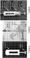
- FIGs 2A, 2B, and 2C are schematic illustrations of a palpation tool attachment according to an embodiment of the current invention.
- Figure 2A depicts an embodiment of an attachment for the manipulation tool 112.
- the attachment includes an instrument extension component and a clear plastic disc.
- the instrument extension component is attached to the manipulation tool 112.
- the clear plastic disc is the contact point for palpating the tissue
- the disc can be made of any other suitable material and can be any other suitable shape.
- the attachment can instead of a separate attachment, the attachment can instead be incorporated into the manipulation tool 112.
- the manipulation tool 112 includes a tool-environment interaction sensor.
- the tool-environment interaction sensor is a force sensor.
- the manipulation tool 112 is arranged so the force sensor measures the force exerted on the environment by the manipulation tool 112. Based on changes in the force measured by the force sensor, the processor 116 can also determine the moment of contact and non-contact between the manipulation tool 112 and the environment.
- the tool-environment interaction data include the force measured by the force sensor and the processor 116 calculates the stiffness estimates based on the measured force and robot position.
- the tool-environment interaction force is not measured by a force sensor but instead estimated from the robot controller, following the method of M. Mahvash, J Gwilliam, R. Agarwal, B. Vagvolgyi, L. Su, D. D. Yuh, and A. M. Okamura, "Force-Feedback Surgical Teleoperator: Controller Design and Palpation Experiments", 16th Symposium on Haptic Interfaces for Virtual Environments and Teleoperator Systems, pp. 465-471, Reno, NV, March 2008 .
- the error between the commanded and actual robot motion is used to estimate the force applied to the robot end-effector.
- Dynamic models of the robot are used to differentiate between forces from the environment (e.g. tissue) and forces from the internal mechanics of the robot (e.g. inertia and friction).
- tool-environment interaction data are visually obtained from the image system 114.
- the processor 116 instructs the manipulation tool 112 to exert a known amount of force on the environment. Based on the image from the image system 114, the processor 116 identifies contact between the manipulation tool 112 and the environment.
- the processor 116 can then determine the amount of displacement in the environment caused by the manipulation tool 112 based on visual analysis of the environment image or based on changes in position data of the manipulation tool 112.
- the tool-environment interaction data include the amount of displacement and the processor 116 calculates the stiffness estimates based on the amount of displacement.
- the tool-environment interaction sensor and visually determined tool-environment interaction data are both used by the surgical robot 100.
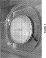
- FIG. 3 is a diagram of a composite image showing a stiffness map overlaid on an image of an environment according to an embodiment of the current invention.
- the processor 116 creates a stiffness map of the tissue from the stiffness estimates.
- the stiffness map is a graphical representation of the estimated stiffness of the tissue.
- the stiffness map is a hue-saturation-luminance (HSL) representation. Hue corresponds to a stiffness value and saturation is calculated by a weighted Gaussian function.
- the processor 116 defines a confidence level for the surrounding areas, which is interpreted as a saturation value. In an embodiment, when multiple confidence levels overlap in the same point, hue is blended to make a blended continuous colored map.
- the processor 116 sums confidence levels to increase reliability at the palpated point.
- the processor 116 updates the stiffness map in real time as new data are gathered.
- the stiffness map is a three-dimensional map (a surface map embedded in three dimensions) and the processor 116 overlays the three-dimensional stiffness map on the environment image.
- the processor 116 receives a stereo view of an environment.
- the stereo view includes two images of the environment from the imaging system 114.
- the processor 116 determines the contours of the environment as shown in the stereo view.
- the processor 116 then creates the composite image so the three dimensional stiffness map corresponds to the contours of the environment.
- the data processing unit may be similar to the processor 116 described with reference to the surgical robot in Figure 1 .
- the data processing unit has at least one input port adapted to receive an environment image from the surgical robot and to receive tool-environment interaction data from the surgical robot, an overlay component in communication with the at least one input port, and an output port in communication with the overlay component.
- the overlay component is adapted to calculate a mechanical property estimate for an area of an environment based on an environment model of tool-environment interaction data, create a composite image comprising a mechanical property map of the mechanical property estimate overlaid on the environment image, and output the composite image to the output port.
- Another embodiment of the current invention is directed to a tangible machine readable storage medium that provides instructions, which when executed by a computing platform cause the computing platform to perform operations including a method including, according to an embodiment of the current invention, determining tool-environment interaction data from a palpation of an area of an environment, calculating a mechanical property estimate of the area of the environment based on the tool-environment interaction data, receiving an environment image, generating a composite image comprising a mechanical property map of the mechanical property estimate overlaid on the environment image, and outputting the composite image on a visual display.
- a real-time graphical overlay technique to display the location of hard objects hidden in soft materials, e.g. a calcified artery inside heart tissue.
- Our approach is to estimate the mechanical properties of tissue using recursive least squares (RLS) and simultaneously overlay a colored stiffness map on the surgeon's visual display.
- the graphical overlay clearly displays the location of a artificial calcified artery, as shown in Figure 3 .
- Another application is online detection of tumors.
- Our proposed technique may also be practical as an alternative to conventional force feedback, since simple force-sensing instruments designed specifically for palpation may be easier to develop than force sensing dexterous manipulation instruments.
- the nonlinear Hunt-Crossley model takes into account the energy loss during impact, which is observed in the Kelvin-Voigt model. While finite element modeling can provide superior tissue modeling, its computational complexity has limited its utility in real-time applications. Misra et al. ( S. Misra, K. T. Ramesh, and A. M. Okamura, "Modeling of tool-tissue interactions for computer-based surgical simulation: A literature review," Presence: Teleoperators and Virtual Environments, vol. 17, no. 5, pp. 463-491, 2008 ) have reviewed the literature on the tool-tissue interaction methods.
- This example describes (1) validation of a mathematical artificial artificial tissue model and (2) use of the model and teleoperated robot to create a real-time graphical overlay to represent tissue stiffness, thus enabling an operator to identify an invisible hard inclusion inside a soft material.
- a hue-saturation-luminance (HSL) representation is used to overlay a semi-transparent colored stiffness map on the environment image.
- Hue corresponds to a stiffness value and saturation is calculated by a weighted Gaussian function.
- a confidence level for the surrounding areas Based on the distance from a palpated point, we define a confidence level for the surrounding areas, which is interpreted as a saturation value.
- hue is blended to make a continuous colored map.
- the confidence levels are summed to increase reliability at the palpated point. This procedure is repeated in real time as new data are added.
- a semi-transparent, colored stiffness map that displays the location of a hard inclusion, without obscuring the surgeon's view of the tissue or surgical instrument.
- the artificial tissue heart model is made from Ecoflex 0030 (part A and B), silicone thinner, and silc pigment (Smooth-on Inc., Easton, PA, USA) mixed in a 24:24:12:1 ratio.
- a coffee stir straw is embedded in the artificial tissue.
- Our surgeon collaborator tested the potential models to make a realistic choice of artificial tissue samples.
- the diameter and thickness of a artificial tissue heart model are approximately 60 mm and 18.5 mm, respectively.
- a coffee stir straw with diameter of 4 mm is embedded at the depth of 5 mm from the surface.
- f ⁇ is an estimated interaction force between the tool and the environment
- x, ⁇ and ⁇ are position, velocity, and acceleration of the tool, respectively.
- the remaining terms, x ⁇ 0 , k ⁇ , b ⁇ , m ⁇ , ⁇ , n ⁇ , ⁇ i , and ⁇ are unknown parameters to be estimated.
- FIG. 2A An instrument extension with a plastic disc, Figure 2A , is attached at the tip of an instrument.
- the diameter of the artificial calcified artery is 4 mm, and the disc is 10 mm in diameter. Due to the size and the flatness of the disc, the tool does not slide off the artery when force is applied.
- the instrument is mounted on a patient-side manipulator of our da Vinci Surgical System, as explained later.
- Figure 2B the artificial heart tissue was placed on a plastic base mounted on a Nano17 transducer (ATI Industrial Automation, Apex, NC, USA).
- ⁇ is a regression vector including known parameters
- ⁇ is an unknown parameter vector
- Model 3 is nonlinear in unknown parameters because of the exponent n ⁇ .
- ⁇ 1 , ⁇ k ⁇ ⁇ Y ⁇ y 1 , ⁇ y 2 , ⁇ , ⁇ y n T ⁇ y i
- Nonlinear least squares has no closed-form solution and requires initial values for the unknown parameters.
- ⁇ 0 [0, 5, 0.3, 1.5] T by trial and error to avoid local minima sometimes observed when ⁇ 0 is a zero vector).
- the iteration number k started from 0 and increased until the norm of the increment parameter vector ⁇ ⁇ was less than 0.001.
- the mean and standard deviation of the force estimation error for each model are summarized in Table I.
- Models 3, 5, 6, and 7 therefore seem to characterize the dynamics of both soft tissue and calcified artery well, while Models 1, 2, and 4 do not.
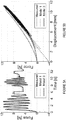
- Figure 4 shows sample plots of interaction data of the tool and the environment.
- Figure 4A and 4B show sample plots of (4A) soft tissue and (4B) calcified artery showing (Top) force vs. elapsed time and (Bottom) force vs. displacement when using a mass-damper-spring model to calculate estimated force.
- Model 3 is a better choice. To discriminate the hard inclusions from the soft surrounding material, we would like to identify a physically meaningful difference. Table II summarizes the estimated parameters of Models 3 and 7. While k ⁇ of Model 3 shows a consistent difference between the artificial tissue and the artificial calcified artery, any parameters of Model 7 do not show a consistent difference.
- Model 3 the Hunt-Crossley model. TABLE II COMPARISON OF ESTIMATED PARAMETERS OF MODELS 3 AND 7 Trial Number Model 3 Model 7 x ⁇ 0 , k ⁇ ⁇ n ⁇ ⁇ 0 ⁇ 1 ⁇ 2 ⁇ Soft Tissue 1 0.708 5.518 0.090 1.679 0.155 3.697 4.588 0.258 2 0.668 5.544 0.115 1570 0.519 0.427 6.687 0286 3 0.416 5.141 0.198 1.391 0.028 5.679 2.461 0.202 4 0.327 4.960 0.134 1.686 0.036 4.867 2.581 0.208 5 1.025 5.984 0.211 1.587 0.373 3.302 5.654 0.306 Calcified Artery 1 0.178 8.687 0.200 1.849 0.352 3.432 6.984 0.294 2 0.249 8.490 0.272 1.934 0.210 4.936 5.701 0.228 3 0.702 10.412 0.411 1.613 0.374 5.374
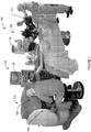
- Figure 6 shows a schematic illustration of a custom version of the da Vinci Surgical System where the master manipulators and the 3D vision display system are located on the right, and the patient-side manipulators and a stereo camera are on the left.
- Our custom version of the da Vinci Surgical System includes three components: master manipulators, 3D vision system, and patient-side manipulators.
- the hardware is provided by Intuitive Surgical, Inc., and a custom control system has been developed at the Johns Hopkins University to achieve bilateral telemanipulation. More details about the teleoperation system and the control architecture are summarized in ( M. Mahvash, J. Gwilliam, R. Agarwal, B. Vagvolgyi, L.-M. Su, D. D. Yuh, and A. M. Okamura, "Force-feedback surgical teleoperator: Controller design and palpation experiments," in 16th Symposium on Haptic Interfaces for Virtual Environments and Teleoperator Systems, pp. 465-471, 2008 ). Although the user received force feedback based on the position-position controller during an experiment, all we need for estimation are tool-environment interaction data.
- Stramigioli "Contact impedance estimation for robotic systems," IEEE Transactions on Robotics, vol. 21, no. 5, pp. 925-935, 2005 ): ⁇ 1 estimates x ⁇ 0 , k ⁇ , and ⁇ , and ⁇ 2 estimates the exponent n ⁇ . Both estimators are interconnected via feedback. Note that we added the position offset x ⁇ 0 to the original method presented in N. Diolaiti, C. Melchiorri, and S. Stramigioli, "Contact impedance estimation for robotic systems," IEEE Transactions on Robotics, vol. 21, no. 5, pp. 925-935, 2005 .
- the result of this calibration is the transformation frame between the Cartesian manipulator tool tip coordinates and the Cartesian camera frame (the camera frame is centered half way between the two cameras).
- a color map using the HSL representation is overlaid on the stereo camera images to display the stiffness of the palpated points. Since the data are analyzed in real time, while the artificial tissue is being palpated, the estimated stiffness and the palpated position data are simultaneously transferred to a vision computer and displayed by a semitransparent color graphical overlay at a rate of 30 Hz. With transparency of 50%, the camera images are clearly visible behind the overlaid image. Thus, the colored stiffness map does not obscure the user's view of the tool or the surface features of the artificial tissue.
- Hue corresponds to stiffness, and the color ranges from green, passing through yellow, to red.
- the range of stiffness k ⁇ from 6 to 10.
- Saturation value is calculated based on a Gaussian function.
- h ( x ) exp(( x - ⁇ ) 2 / ⁇ ), ranging from 0 to 1.
- x and ⁇ are elements of a vector such that the term (x - ⁇ ) 2 is squared distance between the center of the palpated point and the surrounding regions. The standard deviation ⁇ was chosen such that the size of an overlaid circle corresponds to that of the palpation disc.
- Figure 7A and 7B show plots of (7A) confidence level when summing overlapping probability density functions and (7B) hue indicating changes in stiffness and saturation indicating confidence level.
- FIG. 7A A simple summation interpolation technique is used when two or more probability density functions overlap, as shown in Figure 7A . If the sum is more than 1, it is cut off to 1. Luminance is 0.5 for all pixels to show the overlay in color. Figure 7B shows the HSL bar we used in our system.
- Figure 8A-8D are diagrams of composite images as the stiffness map of the underlying environment shown in the image is developed.
- Figure 8 shows four pictures taken during a trial. As soon as contact between the tool and artificial tissue was detected, a semi-transparent colored circle was displayed on the stereo monitor of the surgeon's console. Each palpation at a single location lasted approximately half a second.
- Figure 8A shows the result of the first palpation.
- Figure 8B there are several circles displayed due to random palpation. When a current palpated area is close to others palpated before, the interpolation technique is used to blend the color and sum the confidence level.
- Figure 8C One of the intermediate results is shown in Figure 8C . At this point, one can see a red area that vertically goes through the center.
- the red region is very distinct, as shown in Figure 8D .
- the width of the red region is approximately 8 mm while the actual width of the artificial calcified artery is 4 mm.
- the size of the overlaid circle or the standard deviation of the Gaussian could be reduced to detect more precise size and location of the artificial calcified artery.
- This example presents the use of a teleoperated surgical robot for online estimation of tissue properties, and identification of a hard object hidden in soft materials using a colored stiffness map overlaid on the surgeon's monitor.
- a teleoperated surgical robot for online estimation of tissue properties, and identification of a hard object hidden in soft materials using a colored stiffness map overlaid on the surgeon's monitor.
- the Hunt-Crossley model which provides the lowest force estimation errors in both self-validation and cross-validation and shows a consistent difference between the artificial tissue and the artificial calcified artery.
- Recursive least squares is used to estimate the unknown parameters of the Hunt-Crossley model.
- the estimated stiffness is transmitted to a vision computer to create a graphical overlay using the hue-saturation-luminance map. The hue of the graphical overlay is determined by the stiffness.
- a confidence level is defined by a weighted Gaussian function, based on distance from a palpated point.
- a simple interpolation technique is used. By probing over the surface of an artificial heart tissue, we successfully acquire a color map showing the location of an artificial calcified artery.
Landscapes
- Health & Medical Sciences (AREA)
- Engineering & Computer Science (AREA)
- Surgery (AREA)
- Life Sciences & Earth Sciences (AREA)
- Nuclear Medicine, Radiotherapy & Molecular Imaging (AREA)
- General Health & Medical Sciences (AREA)
- Veterinary Medicine (AREA)
- Public Health (AREA)
- Animal Behavior & Ethology (AREA)
- Biomedical Technology (AREA)
- Heart & Thoracic Surgery (AREA)
- Medical Informatics (AREA)
- Molecular Biology (AREA)
- Pathology (AREA)
- Robotics (AREA)
- Oral & Maxillofacial Surgery (AREA)
- Physics & Mathematics (AREA)
- Gynecology & Obstetrics (AREA)
- Mechanical Engineering (AREA)
- Radiology & Medical Imaging (AREA)
- General Physics & Mathematics (AREA)
- Automation & Control Theory (AREA)
- Theoretical Computer Science (AREA)
- Human Computer Interaction (AREA)
- General Engineering & Computer Science (AREA)
- Instructional Devices (AREA)
- Manipulator (AREA)
- Measuring And Recording Apparatus For Diagnosis (AREA)
Description
- The U. S. Government has a paid-up license in this invention and the right in limited circumstances to require the patent owner to license others on reasonable terms as provided for by the terms of Grant Nos. IIS-0347464, EEC-9731748 and CNS-0722943, awarded by the National Science Foundation, and of Grant No. R01-EB002004, awarded by the National Institutes of Health.
- The current invention relates to environment property estimation and graphical display, and more particularly to a surgical robot operable to graphically display environment property estimates.
- A teleoperated robot-assisted surgical system such as the da Vinci (Intuitive Surgical Inc., Sunnyvale, CA, USA) provides a number of advantages over conventional minimally invasive surgery (MIS). It enhances dexterity, enables more precise motions, and provides 3-dimensional (3D) visualisation. However, the lack of haptic feedback has been recognised as one of the drawbacks of such teleoperated robot-assisted minimally invasive surgery (RMIS) systems (F. W. Mohr, V. Falk, A. Diegeler, T. Walther, J. F. Gummert, J. Bucerius, S. Jacobs, and R. Autschbach, "Computer-enhanced 'robotic' cardiac surgery: experience in 148 patients," The Journal of Thoracic and Cardiovascular Surgery, vol. 121, no. 5, pp. 842-853, 2001). Although many research groups, e.g. M. Mahvash, J. Gwilliam, R. Agarwal, B. Vagvolgyi, L.-M. Su, D. D. Yuh, and A. M. Okamura, "Force-feedback surgical teleoperator: Controller design and palpation experiments," in 16th Symposium on Haptic Interfaces for Virtual Environments and Teleoperator Systems, pp. 465-471, 2008, H. Mayer, I. Nagy, A. Knoll, E. U. Braun, R. Bauernschmitt, and R. Lange, "Haptic feedback in a telepresence system for endoscopic heart surgery," Presence: Teleoperators and Virtual Environments, vol. 16, no. 5, pp. 459-470, 2007, and M. Tavakoli, R. Patel, M. Moallem, and A. Aziminejad, Haptics for Teleoperated Surgical Robotic Systems (New Frontiers in Robotics series), World Scientific Publishing Company, 2008, have studied teleoperation with haptic feedback for surgical applications, the trade-off between stability and transparency, and force sensor issues such as cost, biocompatibility, and sterilizability, make it difficult to develop a practical system (based on current commercially available surgical robots) with realistic haptic feedback (A. M. Okamura, L. N. Verner, C. E. Reiley, and M. Mahvash, "Haptics for robot-assisted minimally invasive surgery," in Proceedings of the International Symposium Robotics Research, Hiroshima, Japan, Nov. 26-29, 2007) and (A. M. Okamura, "Haptic feedback in robot-assisted minimally invasive surgery," Current Opinion in Urology, vol. 19, no. 1, pp. 102-107, 2009). Thus, surgeons using current RMIS systems principally rely on visual cues such as tissue deformation to estimate how much force a remote tool is applying to tissue.
- During a procedure, surgeons often manually palpate biological tissues to investigate anatomical structures. Palpation provides both force-displacement and distributed tactile information. Tissue abnormalities can be differentiated from normal tissue by their mechanical properties, such as stiffness (e.g., K. Hoyt, B. Castaneda, M. Zhang, P. Nigwekar, P. A. di Sant'agnese, J. V. Joseph, J. Strang, D. J. Rubens, and K. J. Parker. Tissue elasticity properties as biomarkers for prostate cancer. Cancer Biomark, 4(4-5):213-225, 2008. Neurophys, 73:88, 1995). In coronary artery bypass grafting surgery (CABG), palpation is especially beneficial in detecting where to place grafts. It is better to graft soft undiseased arteries that are difficult to differentiate visually from calcified arteries. Grafts should not be placed adjacent to or directly onto a calcified artery segment. Without force feedback, finding the location of a calcified artery in heart tissue is quite challenging, and surgeons may be unable to determine the best location for anastomosis (F. W. Mohr, V. Falk, A. Diegeler, T. Walther, J. F. Gummert, J. Bucerius, S. Jacobs, and R. Autschbach, "Computer-enhanced 'robotic' cardiac surgery: experience in 148 patients," The Journal of Thoracic and Cardiovascular Surgery, vol. 121, no. 5, pp. 842-853, 2001).
- There is thus a need for improved surgical robots, components, and methods for environment property estimation.
- Augmented-reality visualisation of tissue stiffness data is disclosed in TSUCHIMOTO T ET AL: "Augmented-Reality Visualisation of Tissue Stiffness Data", MEDICAL INFORMATION VISUALISATION - BIOMEDICAL VISUALISATION, 2006. ME DIVIS 2006. INTERNATIONAL CONFERENCE ON LONDON, UK 05-07 JULY 2006, PISCATAWAY, NJ, USA, IEEE, 5 July 2006, pages 59-64. Tissue stiffness values are measured by a tactile sensor. A head-mounted display with a small video camera and a notebook computer are employed. Two markers are used to create augmentation of a human organ by computer-generated visual information. One marker is attached to the patient's body and used to track the spacial position of the human organ where measurements are done. Another marker is integrated into the tactile sensor. Results of stiffness measurements are depicted as semi-transparent three-dimensional objects superimposed on the patient's body.
- A surgical robot according to an embodiment of the current invention has an imaging system comprising at least one stereo camera, a processor in communication with the imaging system, a manipulation system in communication with the processor, and a visual display in communication with the processor, the manipulation system including a manipulation tool. The processor is operable to instruct the manipulation system to palpate an area of an environment with the manipulation tool, receive tool-environment interaction data for an interaction between the manipulation tool and the environment during the palpation, use an environment model and apply the tool-environment interaction data to the environment model to estimate unknown parameters of the environment model, calculate a mechanical property estimate for the area of the environment based on the estimated unknown parameters of the environment model, determine contours of the environment based on an environmental image from said at least one stereo camera, create a composite image comprising a mechanical property map of the mechanical property estimate for the area of the environment, the mechanical property map being overlaid on the environment image from said at least one stereo camera so that the mechanical property map corresponds to the contours of the environment, and output the composite image on the visual display.
- A tangible machine readable storage medium that provides instructions, which when executed by a computing platform comprising a processor, cause the computing platform to perform operations including a method including, according to an embodiment of the current invention, instructing a manipulation system in communication with said processor to palpate an area of an environment with a manipulation tool of said manipulation system, receiving tool-environment interaction data for an interaction between the manipulation tool and the environment during the palpation, using an environment model and applying the tool-environment interaction data to the environment model to estimate unknown parameters of the environment model, calculating a mechanical property estimate of the area of the environment based on the unknown parameters of the environment model, receiving a stereo image of the environment, determining contours of the environment based on the stereo image of the environment, generating a composite image comprising a mechanical property map of the mechanical property estimate overlaid on the environment image so that the mechanical property map corresponds to the contours of the environment, and outputting the composite image on a visual display in communication with said processor.
- The invention may be better understood by reading the following detailed description with reference to the accompanying figures, in which:
-
Figure 1 is a schematic illustration of a surgical robot for tissue property estimation and graphical display according to an embodiment of the current invention; -
Figures 2A, 2B, and 2C are schematic illustrations of a palpation tool attachment according to an embodiment of the current invention; -
Figure 3 is a diagram of a composite image showing a mechanical property map overlaid on an image of an environment according to an embodiment of the current invention; -
Figure 4A and 4B show sample plots of (4A) artificial soft tissue and (4B) artificial calcified artery showing (Top) force vs. elapsed time and (Bottom) force vs. displacement when using a mass-damper-spring model to calculate estimated force according to an embodiment of the current invention; -
Figure 5A and 5B show force plots of (5A) force vs. elapsed time and (5B) force vs. displacement from one of the artificial calcified artery according to an embodiment of the current invention; -
Figure 6 shows a schematic illustration of a custom version of the da Vinci Surgical System where the master manipulators and the 3D vision display system are located on the right, and the patient-side manipulators and a stereo camera are on the left according to an embodiment of the current invention; -
Figure 7A and 7B show plots of (7A) confidence level when summing overlapping probability density functions and (7B) hues indicating changes in stiffness and saturations indicating confidence level according to an embodiment of the current invention; and -
Figure 8A-8D are diagrams of composite images as the stiffness map of the underlying environment shown in the image is developed according to an embodiment of the current invention. - In describing embodiments of the present invention illustrated in the drawings, specific terminology is employed for the sake of clarity. However, the invention is not intended to be limited to the specific terminology so selected. It is to be understood that each specific element includes all technical equivalents which operate in a similar manner to accomplish a similar purpose.
-
Figure 1 is a schematic illustration of asurgical robot 100 for environment property estimation and graphical display according to an embodiment of the current invention. Thesurgical robot 100 includes amaster console 102 and a patient-side manipulator 104. Themaster console 102 includes avisual display 106 andmanipulator 108. The patient-side manipulator 104 includes amanipulation system 110. In an embodiment, themanipulation system 110 includes amanipulation tool 112 and animaging system 114. In the embodiment, asurgical robot 100 includes animaging system 114 including at least one camera, aprocessor 116 in communication with theimaging system 114, amanipulation system 110 in communication with theprocessor 116, and avisual display 106 in communication with theprocessor 116. - The
processor 116 calculates a mechanical property estimate for an area of an environment based on an environment model of tool-environment interaction data, creates a composite image comprising a mechanical property map of the mechanical property estimate overlaid on an environment image from the at least one camera, and outputs the composite image on thevisual display 106. - In an embodiment, the mechanical property is a stiffness. The stiffness can be linear or nonlinear. In another embodiment, the mechanical property is linear or nonlinear damping. In another embodiment, the mechanical property is damping. In another embodiment, the mechanical property is any mechanical property that can be detected by the system, such as, e.g., but not limited to, stiffness, damping, or mass, etc.
- In an embodiment, a user can utilize the
surgical robot 100 to provide a composite image so the user can identify areas of the tissue abnormalities based on estimated stiffness of the tissue. The estimated stiffness is calculated using tool-environment interaction data from palpation of the tissue. The user manipulates themanipulators 108 of themaster console 102 to manually control thesurgical robot 100 to palpate the tissue area. Alternatively, the user selects the area of tissue to palpate, but thesurgical robot 100 controls the palpation of the tissue area. In another embodiment, thesurgical robot 100 automatically palpates the tissue including the tissue abnormality area. - To carry out palpation of the tissue area, the
processor 116 of thesurgical robot 100 instructs themanipulation system 110 to palpate an area of tissue with themanipulation tool 112. Theprocessor 116 receives tool-environment interaction data for the interaction between themanipulation tool 112 and the tissue during the palpation. - The tool-environment interaction data include data for the position of the
manipulation tool 112 when palpating the tissue area. The tool-environment interaction data can also include other data, such as, for example, velocity and acceleration of themanipulation tool 112, the force exerted by themanipulation tool 112 on the tissue, or the amount of displacement themanipulation tool 112 causes to the tissue. While themanipulation tool 112 is in contact with the tissue, many characteristics of themanipulation tool 112 also correspond to characteristics of the tissue. For example, while themanipulation tool 112 is in contact with the tissue, the change in position of themanipulation tool 112 corresponds to the change in position of the tissue. - The
processor 116 can receive the tool-environment interaction data from a variety of sources. In an embodiment, the position of themanipulation tool 112 can be known by theprocessor 116 thorough position sensors in themanipulation system 110, or through analysis of the data from theimaging system 114. Theprocessor 116 monitors the position of themanipulation tool 112 and calculates the velocity and acceleration of the manipulation tool based on changes in the position of themanipulation tool 112. Alternatively, themanipulation tool 112 includes velocity and acceleration sensors in communication with theprocessor 116. Determination of other tool-environment interaction data is further described below in regards toFigures 2A, 2B, and 2C . - During a single palpation, the
processor 116 receives multiple sets of tool-environment interaction data. Based on the tool-environment interaction data, theprocessor 116 then calculates a stiffness estimate, representing an estimated stiffness, for the area of tissue palpated. - To calculate the stiffness estimate for the area of the tissue, the
processor 116 uses a tissue model and applies the tool-environment interaction data to the tissue model to estimate the unknown parameters of the tissue model. Various tissue models can be used, such as, e.g., but not limited to, a Kelvin-Voigt model, a Mass-damper-spring model, a Hunt-Crossley model, a 2nd order polynomial model, a 3rd order polynomial model, a 4th order polynomial model, or a 2nd order polynomial and velocity-dependent model. Various types of estimation techniques for estimating the unknown parameters of the tissue model can also be used, such as, e.g., but not limited to, recursive least squares, adaptive identification, the Kalman filter, and signal processing. Theprocessor 116 obtains the stiffness estimate from the estimated unknown parameters of the tissue model. - Using the stiffness estimate and the environment image from the
imaging system 114, theprocessor 116 creates the composite image. The composite image includes a stiffness map of the stiffness estimate overlaid on an environment image from the at least one camera. The stiffness map is a graphical representation of the calculated stiffness estimate of one or more areas of the tissue, and is further described below in regards toFigure 3 . - The
processor 116 creates the composite image such that the areas of the stiffness map correspond to the areas of the environment the stiffness map overlays in the environment image. Creating a composite image includes creating the stiffness map based on translation of the stiffness estimate to the environment image. Theprocessor 116 analyzes the environment image to translate an area of the environment to an area of the environment image showing the area of the environment. Based on the translation, theprocessor 116 then creates the stiffness map and overlays the stiffness map on the environment image. Theprocessor 116 overlays the stiffness map in a semi-transparent fashion so the underlying environment image is still visible in the composite image. The composite image is then output on thevisual display 106. According to an embodiment, theprocessor 116 creates the composite image in real time. - The
visual display 106 shows users the composite image. Thevisual display 106 is a stereo display. Thevisual display 106 shows a three dimensional stereo view to the user through two separate displays, one display for each eye. Each of the displays shows a different composite image corresponding to the viewpoint of the environment for that eye. In another embodiment, thevisual display 106 is instead anon-stereo display 118. -
Figures 2A, 2B, and 2C are schematic illustrations of a palpation tool attachment according to an embodiment of the current invention.Figure 2A depicts an embodiment of an attachment for themanipulation tool 112. The attachment includes an instrument extension component and a clear plastic disc. As shown inFigure 2B , the instrument extension component is attached to themanipulation tool 112. Although in this embodiment, the clear plastic disc is the contact point for palpating the tissue, the disc can be made of any other suitable material and can be any other suitable shape. Additionally, instead of a separate attachment, the attachment can instead be incorporated into themanipulation tool 112. - As shown in
Figure 2C , in an embodiment, themanipulation tool 112 includes a tool-environment interaction sensor. The tool-environment interaction sensor is a force sensor. Themanipulation tool 112 is arranged so the force sensor measures the force exerted on the environment by themanipulation tool 112. Based on changes in the force measured by the force sensor, theprocessor 116 can also determine the moment of contact and non-contact between themanipulation tool 112 and the environment. The tool-environment interaction data include the force measured by the force sensor and theprocessor 116 calculates the stiffness estimates based on the measured force and robot position. - In another embodiment, the tool-environment interaction force is not measured by a force sensor but instead estimated from the robot controller, following the method of M. Mahvash, J Gwilliam, R. Agarwal, B. Vagvolgyi, L. Su, D. D. Yuh, and A. M. Okamura, "Force-Feedback Surgical Teleoperator: Controller Design and Palpation Experiments", 16th Symposium on Haptic Interfaces for Virtual Environments and Teleoperator Systems, pp. 465-471, Reno, NV, March 2008. In this method, the error between the commanded and actual robot motion is used to estimate the force applied to the robot end-effector. Dynamic models of the robot are used to differentiate between forces from the environment (e.g. tissue) and forces from the internal mechanics of the robot (e.g. inertia and friction).
- In another embodiment, tool-environment interaction data are visually obtained from the
image system 114. Theprocessor 116 instructs themanipulation tool 112 to exert a known amount of force on the environment. Based on the image from theimage system 114, theprocessor 116 identifies contact between themanipulation tool 112 and the environment. Theprocessor 116 can then determine the amount of displacement in the environment caused by themanipulation tool 112 based on visual analysis of the environment image or based on changes in position data of themanipulation tool 112. The tool-environment interaction data include the amount of displacement and theprocessor 116 calculates the stiffness estimates based on the amount of displacement. According to another embodiment, the tool-environment interaction sensor and visually determined tool-environment interaction data are both used by thesurgical robot 100. -
Figure 3 is a diagram of a composite image showing a stiffness map overlaid on an image of an environment according to an embodiment of the current invention. Theprocessor 116 creates a stiffness map of the tissue from the stiffness estimates. The stiffness map is a graphical representation of the estimated stiffness of the tissue. In an embodiment, the stiffness map is a hue-saturation-luminance (HSL) representation. Hue corresponds to a stiffness value and saturation is calculated by a weighted Gaussian function. Based on the distance from a palpated point, theprocessor 116 defines a confidence level for the surrounding areas, which is interpreted as a saturation value. In an embodiment, when multiple confidence levels overlap in the same point, hue is blended to make a blended continuous colored map. Theprocessor 116 sums confidence levels to increase reliability at the palpated point. In an embodiment, theprocessor 116 updates the stiffness map in real time as new data are gathered. - In an embodiment, the stiffness map is a three-dimensional map (a surface map embedded in three dimensions) and the
processor 116 overlays the three-dimensional stiffness map on the environment image. Theprocessor 116 receives a stereo view of an environment. The stereo view includes two images of the environment from theimaging system 114. Using the stereo view, theprocessor 116 determines the contours of the environment as shown in the stereo view. Theprocessor 116 then creates the composite image so the three dimensional stiffness map corresponds to the contours of the environment. - Another embodiment of the current invention is directed to a data processing unit for use with a surgical robot. For example, the data processing unit may be similar to the
processor 116 described with reference to the surgical robot inFigure 1 . The data processing unit has at least one input port adapted to receive an environment image from the surgical robot and to receive tool-environment interaction data from the surgical robot, an overlay component in communication with the at least one input port, and an output port in communication with the overlay component. The overlay component is adapted to calculate a mechanical property estimate for an area of an environment based on an environment model of tool-environment interaction data, create a composite image comprising a mechanical property map of the mechanical property estimate overlaid on the environment image, and output the composite image to the output port. - Another embodiment of the current invention is directed to a tangible machine readable storage medium that provides instructions, which when executed by a computing platform cause the computing platform to perform operations including a method including, according to an embodiment of the current invention, determining tool-environment interaction data from a palpation of an area of an environment, calculating a mechanical property estimate of the area of the environment based on the tool-environment interaction data, receiving an environment image, generating a composite image comprising a mechanical property map of the mechanical property estimate overlaid on the environment image, and outputting the composite image on a visual display.
- Manual palpation of tissue and organs during a surgical procedure provides clinicians with valuable information for diagnosis and surgical planning. In present-day robot assisted minimally invasive surgery systems, lack of perceptible haptic feedback makes it challenging to detect a tumor in an organ or a calcified artery in heart tissue. This example presents an automated tissue property estimation method and a real-time graphical overlay that allow an operator to discriminate hard and soft tissues. We first evaluate experimentally the properties of an artificial tissue and compare seven possible mathematical tissue models. Self-validation as well as cross-validation confirm that the Hunt-Crossley model best describes the experimentally observed artificial tissue properties and is suitable for our purpose. Second, we present the development of a system in which the artificial tissue is palpated using a teleoperated surgical robot, and the stiffness of the Hunt-Crossly model is estimated in real time by recursive least squares. A real-time visual overlay representing tissue stiffness is created using a hue-saturation-luminance representation on a semi-transparent disc at the tissue surface. Hue depicts the stiffness at a palpated point and saturation is calculated based on distance from the point. A simple interpolation technique creates a continuous stiffness color map. In an experiment, the graphical overlay successfully shows the location of an artificial calcified artery hidden in artificial tissue.
- In this work, we propose a real-time graphical overlay technique to display the location of hard objects hidden in soft materials, e.g. a calcified artery inside heart tissue. Our approach is to estimate the mechanical properties of tissue using recursive least squares (RLS) and simultaneously overlay a colored stiffness map on the surgeon's visual display. The graphical overlay clearly displays the location of a artificial calcified artery, as shown in
Figure 3 . Another application is online detection of tumors. Our proposed technique may also be practical as an alternative to conventional force feedback, since simple force-sensing instruments designed specifically for palpation may be easier to develop than force sensing dexterous manipulation instruments. - Human biological tissues are known to exhibit nonlinear properties and include inhomogeneous structures. For computational efficiency, however, many researchers assume a simple linear tissue model. In particular, a classical linear tissue model, such as a spring model or the Kelvin-Voigt model, is commonly employed (R. Corteso, J. Park, and O. Khatib, "Real-time adaptive control for haptic telemanipulation with kalman active observers," IEEE Transactions on Robotics, vol. 22, no. 5, pp. 987-999, 2006)(R. Corteso, W. Zarrad, P. Poignet, O. Company, and E. Dombre, "Haptic control design for robotic-assisted minimally invasive surgery," in IEEE International Conference on Intelligent Robots and Systems, pp. 454-459, 2006)(G. De Gersem, H. V. Brussel, and J. V. Sloten, "Enhanced haptic sensitivity for soft tissues using teleoperation with shaped impedance reflection," in World Haptics Conference (WHC) CD-ROM Proceedings, 2005)(S. Misra and A. M. Okamura, "Environment parameter estimation during bilateral telemanipulation," in 14th Symposium on Haptic Interfaces for Virtual Environments and Teleoperator Systems, pp. 301-307, 2006)(X. Wang, P. X. Liu, D. Wang, B. Chebbi, and M. Meng, "Design of bilateral teleoperators for soft environments with adaptive environmental impedance estimation," in IEEE International Conference on Robotics and Automation, pp. 1127-1132, 2005). Diolaiti et al. (N. Diolaiti, C. Melchiorri, and S. Stramigioli, "Contact impedance estimation for robotic systems," IEEE Transactions on Robotics, vol. 21, no. 5, pp. 925-935, 2005) used the Hunt-Crossley model (K. Hunt and F. Crossley, "Coefficient of restitution interpreted as damping in vibroimpact," ASME Journal of Applied Mechanics, vol. 42, no. 2, pp. 440-445, 1975). The nonlinear Hunt-Crossley model takes into account the energy loss during impact, which is observed in the Kelvin-Voigt model. While finite element modeling can provide superior tissue modeling, its computational complexity has limited its utility in real-time applications. Misra et al. (S. Misra, K. T. Ramesh, and A. M. Okamura, "Modeling of tool-tissue interactions for computer-based surgical simulation: A literature review," Presence: Teleoperators and Virtual Environments, vol. 17, no. 5, pp. 463-491, 2008) have reviewed the literature on the tool-tissue interaction methods.
- For online environment parameter estimation, there exist several methods, including RLS (X. Wang, P. X. Liu, D. Wang, B. Chebbi, and M. Meng, "Design of bilateral teleoperators for soft environments with adaptive environmental impedance estimation," in IEEE International Conference on Robotics and Automation, pp. 1127-1132, 2005)(N. Diolaiti, C. Melchiorri, and S. Stramigioli, "Contact impedance estimation for robotic systems," IEEE Transactions on Robotics, vol. 21, no. 5, pp. 925-935, 2005)(M. B. Colton and J. M. Hollerbach, "Identification of nonlinear passive devices for haptic simulations," in WHC '05: Proceedings of the First Joint Eurohaptics Conference and Symposium on Haptic Interfaces for Virtual Environment and Teleoperator Systems, (Washington, DC, USA), pp. 363-368, IEEE Computer Society, 2005)(L. J. Love and W. J. Book, "Environment estimation for enhanced impedance control," in IEEE International Conference on Robotics and Automation, pp. 1854-1858, 1995), adaptive identification (S. Misra and A. M. Okamura, "Environment parameter estimation during bilateral telemanipulation," in 14th Symposium on Haptic Interfaces for Virtual Environments and Teleoperator Systems, pp. 301-307, 2006)(K. Hashtrudi-Zaad and S. E. Salcudean, "Adaptive transparent impedance reflecting teleoperation," in IEEE International Conferenceon Robotics and Automation, pp. 1369-1374, 1996)(H. Seraji and R. Colbaugh, "Force tracking in impedance control," IEEE Transactions on Robotics, vol. 16, no. 1, pp. 97-117, 1997>AS. K. Singh and D. O. Popa, "An analysis of some fundamental problems in adaptive control of force and impedance behavior: Theory and experiments," IEEE Transactions on Robotics and Automation, vol. 11, no. 6, pp. 912-921, 1995), Kalman filter approaches (R. Corteso, J. Park, and O. Khatib, "Real-time adaptive control for haptic telemanipulation with kalman active observers," IEEE Transactions on Robotics, vol. 22, no. 5, pp. 987-999, 2006)(R. Corteso, W. Zarrad, P. Poignet, O. Company, and E. Dombre, "Haptic control design for robotic-assisted minimally invasive surgery," in IEEE International Conference on Intelligent Robots and Systems, pp. 454-459, 2006)(G. De Gersem, H. V. Brussel, and J. V. Sloten, "Enhanced haptic sensitivity for soft tissues using teleoperation with shaped impedance reflection," in World Haptics Conference (WHC) CD-ROM Proceedings, 2005), and a multiestimator technique (T. Yamamoto, M. Bernhardt, A. Peer, M. Buss, and A. M. Okamura, "Multi-estimator technique for environment parameter estimation during telemanipulation," in IEEE International Conference on Biomedical Robotics and Biomechatronics, pp. 217-223, 2008). Erickson et al. (D. Erickson, M. Weber, and I. Sharf, "Contact stiffness and damping estimation for robotic systems," The International Journal of Robotics Research, vol. 22, no. 1, pp. 41-57, 2003) reviewed and compared four methods: RLS, indirect adaptive control, model-reference adaptive control, and a signal processing technique. They estimated environment stiffness and damping to improve force tracking and stability of impedance control for the application of robotic assembly operations. They concluded that indirect adaptive control, with persistent excitation, showed the best performance among the four schemes. Yamamoto et al. (T. Yamamoto, M. Bernhardt, A. Peer, M. Buss, and A. M. Okamura, "Multi-estimator technique for environment parameter estimation during telemanipulation," in IEEE International Conference on Biomedical Robotics and Biomechatronics, pp. 217-223, 2008) compared RLS, adaptive identification, and the multi-estimator technique to estimate unknown parameters of the Kelvin-Voigt model for surgical applications. They recommend RLS or the multi-estimator for online tissue parameter estimation.
- Some hard inclusions can be found using ultrasound, and prior work has examined intuitive visualization of laparoscopic ultrasound data using the da Vinci Surgical System (J. Leven, D. Burschka, R. Kumar, G. Zhang, S. Blumenkranz, X. Dai, M. Awad, G. D. Hager, M. Marohn, M. Choti, C. Hasser, and R. H. Taylor, "Davinci canvas: A telerobotic surgical system with integrated, robot-assisted, laparoscopic ultrasound capability," in Medical Image Computing and Computer-Assisted Intervention (MICCAI), pp. 811-818, 2005). Elastography, which typically uses ultrasound and displays strain distributions in the soft tissues, is an effective method to detect tumors. The main disadvantage of elastography is that it is computationally expensive (J. Ophir, S. Alam, B. Garra, F. Kallel, E. Konofagou, T. Krouskop, C. Merritt, R. Righetti, R. Souchon, S. Srinivasan, and T. Varghese, "Elastography: Imaging the elastic properties of soft tissues with ultrasound," in Journal of Medical Ultrasonics, vol. 29, pp. 155-171, 2002). Some novel devices specialized for localization of tumors have been developed, e.g. Tactile Imaging (P. S. Wellman, E. P. Dalton, D. Krag, K. A. Kern, and R. D. Howe, "Tactile imaging of breast masses first clinical report," Archives of Surgery, vol. 136, pp. 204-208, 2001), Tactile Imaging System (A. P. Miller, W. J. Peine, J. S. Son, and Z. T. Hammoud, "Tactile imaging system for localizing lung nodules during video assisted thoracoscopic surgery," in IEEE International Conference on Robotics and Automation, pp. 2996-3001, 2007), Active Strobe Imager (M. Kaneko, C. Toya, and M. Okajima, "Active strobe imager for visualizing dynamic behavior of tumors," in IEEE International Conference on Robotics and Automation, pp. 3009-3014, 2007), PVDF-sensing grippers (J. Dargahi, S. Najarian, and R. Ramezanifard, "Graphical display of tactile sensing data with application in minimally invasive surgery," Canadian Journal of Electrical and Computer Engineering, vol. 32, no. 3, pp. 151-155, 2007), Tactile Sensing Instrument (A. L. Trejos, J. Jayender, M. T. Perri, M. D. Naish, R. V. Patel, and R. A. Malthaner, "Experimental evaluation of robot-assisted tactile sensing for minimally invasive surgery," in IEEE International Conference on Biomedical Robotics and Biomechatronics, pp. 971-976, 2008), and Air-Cushion Force Sensitive Probe (K. Althoefer, D. Zbyszewski, H. Liu, P. Puangmali, L. Seneviratne, B. Challacombe, P. Dasgupta, and D. Murphy, "Air-cushion force sensitive probe for soft tissue investigation during minimally invasive surgery," in IEEE Conference on Sensors, pp. 827-830, 2008), but none have been tested in RMIS systems yet.
- This example describes (1) validation of a mathematical artificial artificial tissue model and (2) use of the model and teleoperated robot to create a real-time graphical overlay to represent tissue stiffness, thus enabling an operator to identify an invisible hard inclusion inside a soft material.
- To choose an accurate mathematical model of the artificial tissue, we analyzed experimental tool-environment interaction data and compared seven candidate models. By post processing using the least-squares method, we evaluated the model accuracy based on the force estimation error in both self-validation and cross-validation. The Hunt-Crossley model was chosen because of its accuracy and a stiffness term that distinguishes hard objects from the soft materials. Since in the long term we aim to model real tissues, which are inhomogeneous and complex, both validations are useful to mathematically approximate tissue dynamic behavior.
- We have also developed an online graphical overlay technique that displays stiffness distribution based on estimated tissue properties. A hue-saturation-luminance (HSL) representation is used to overlay a semi-transparent colored stiffness map on the environment image. Hue corresponds to a stiffness value and saturation is calculated by a weighted Gaussian function. Based on the distance from a palpated point, we define a confidence level for the surrounding areas, which is interpreted as a saturation value. When multiple confidence levels overlap in the same point, hue is blended to make a continuous colored map. Also, the confidence levels are summed to increase reliability at the palpated point. This procedure is repeated in real time as new data are added. As a result, we have achieved a semi-transparent, colored stiffness map that displays the location of a hard inclusion, without obscuring the surgeon's view of the tissue or surgical instrument.
- Although it is nearly impossible to find a perfect mathematical model of a real or artificial tissue, there may be one that can approximate tissue dynamic behavior. Seven possible models are considered, however other models can be used. From tool-environment interaction data, we compare all of the models and evaluate the accuracy based on force estimation error.
- The artificial tissue heart model is made from Ecoflex 0030 (part A and B), silicone thinner, and silc pigment (Smooth-on Inc., Easton, PA, USA) mixed in a 24:24:12:1 ratio. To simulate a calcified artery, a coffee stir straw is embedded in the artificial tissue. Our surgeon collaborator tested the potential models to make a realistic choice of artificial tissue samples. The diameter and thickness of a artificial tissue heart model are approximately 60 mm and 18.5 mm, respectively. A coffee stir straw with diameter of 4 mm is embedded at the depth of 5 mm from the surface.
- We compare the seven models listed in Table I. f̂ is an estimated interaction force between the tool and the environment, and x, ẋ and ẍ are position, velocity, and acceleration of the tool, respectively. The remaining terms, x̂ 0, k̂, b̂, m̂, λ̂, n̂, α̂i , and β, are unknown parameters to be estimated.
TABLE I SEVEN ENVIRONMENT MODELS AND COMPARISON OF MEAN AND STANDARD DEVIATION OF FORCE ESTIMATION ERROR # Model Name Equation of Model Self-Validation Cross-Validation Soft Tissue Calcified Artery Soft Tissue Calcified Artery Mean Std Mean Std Mean Std Mean Std 1 Kelvin-Voigt f̂ = x̂ 0 + k̂x + b̂ẋ 0.149 0.120 0.478 0.389 0375 0.163 0.645 0.465 2 mass-damper-spring f̂ = x̂ 0 + k̂x + b̂ẋ + m̂ẍ 0.135 0.108 0.445 0.352 0.364 0.151 0.637 0.438 3 Hunt-Crossley f̂ = x̂ 0 + k̂x̂ + λ̂xẋ 0.078 0.081 0.245 0.235 0.369 0.104 0.431 0.271 4 2nd order polynomial f̂ = α̂ 0 + α̂ 1x + α̂ 2 x 2 0.095 0.104 0.291 0.275 0.369 0.112 0.439 0.288 5 3rd order polynomial f̂ = α̂ 0 + α̂ 1 x + α̂ 2 x 2 + α̂ 3 x 3 0.091 0.102 0.256 0.285 0.392 0.140 0.448 0.323 6 4th order polynomial f̂ = α̂ 0 + α̂ 1 x + α̂ 2 x 2 + α̂ 3 x 3 + α̂ 4 x 4 0.090 0.102 0.232 0.271 0.406 0.170 0.514 0.342 7 2nd order polynomial + velocity-dependent f̂ = α̂ 0 + α̂ 1 x + α̂ 2 x 2 + β̂ẋ 0.074 0.070 0.234 0.198 0.391 0.134 0.464 0.322 - We first conducted a preliminary palpation experiment to obtain the tool-environment interaction data. An instrument extension with a plastic disc,
Figure 2A , is attached at the tip of an instrument. The diameter of the artificial calcified artery is 4 mm, and the disc is 10 mm in diameter. Due to the size and the flatness of the disc, the tool does not slide off the artery when force is applied. The instrument is mounted on a patient-side manipulator of our da Vinci Surgical System, as explained later. As shown inFigure 2B , the artificial heart tissue was placed on a plastic base mounted on a Nano17 transducer (ATI Industrial Automation, Apex, NC, USA). - There were five trials each for the soft tissue and calcified artery. During a trial, the instrument was restricted to up and down motions, so the system had one degree of freedom in this preliminary experiment. Probed locations were different trial by trial to obtain a wide range of data. The patient-side manipulator was teleoperated by a master manipulator and a user received haptic feedback based on a position-position controller (M. Mahvash and A. M. Okamura, "Enhancing transparency of a position-exchange teleoperator," in Second Joint Eurohaptics Conference and Symposium on Haptic Interfaces for Virtual Environment and Teleoperator Systems (World Haptics), pp. 470-475, 2007). Position, velocity, and acceleration of the tool and the applied forces to the artificial tissue were recorded.
- We post-processed the data for each trial and the unknown parameters and interaction force were estimated for each model. To verify model accuracy, batch post-processing was employed.
Models 

- In (1), ϕ is a regression vector including known parameters, θ is an unknown parameter vector, and in (2) the subscript k (1 ≤ k ≤ n) denotes t = kT with sampling time T.
-
Model 3 is nonlinear in unknown parameters because of the exponent n̂. We used nonlinear least squares with the Gauss-Newton method. Let us define


- Nonlinear least squares has no closed-form solution and requires initial values for the unknown parameters. We set θ 0 = [0, 5, 0.3, 1.5] T by trial and error to avoid local minima sometimes observed when θ 0 is a zero vector). Note that the units of force and position are Newton and centimeter, respectively, throughout this document. The iteration number k started from 0 and increased until the norm of the increment parameter vector Δ θ was less than 0.001.
1) Self-Validation: The force estimation error is defined as
The mean and standard deviation of the force estimation error for each model are summarized in Table I. Since there are five sets of the palpation data for the soft tissue and calcified artery, the mean and standard deviation are averaged. The lower the mean and standard deviation of the force estimation errors a model yields, the more accurate it is.Models Models Figure 4 shows sample plots of interaction data of the tool and the environment.
Figure 4A and 4B show sample plots of (4A) soft tissue and (4B) calcified artery showing (Top) force vs. elapsed time and (Bottom) force vs. displacement when using a mass-damper-spring model to calculate estimated force.
2) Cross-Validation: From self-validation, we obtained one set of estimated parameters from a single trial for each model. In cross-validation, those parameters were used to calculate estimated forces for the other trials. For instance, an estimated parameter vector fromtrial 1 was used to calculate force for trials 1-5. This was done for every trial. Therefore, 52 = 25 force estimation errors were calculated for each model. In Table I, the mean and standard deviation of the force estimation error for each model are summarized.Figure 5 shows a comparison of measured and recreated force, based on one of the trial data for the calcified artery, forModels
Figure 5A and 5B show force plots of (5A) force vs. elapsed time and (5B) force vs. displacement from one of the calcified artery.
3) Analysis of Both Validations: In self-validation, the higher the order of a polynomial function model is, the lower errors the model yields.Models Model 6 is good in self-validation but not in cross-validation. From both validation tests, eitherModel 3 or 7 is appropriate for our artificial tissue heart model with the calcified artery. For our purpose, however,Model 3 is a better choice. To discriminate the hard inclusions from the soft surrounding material, we would like to identify a physically meaningful difference. Table II summarizes the estimated parameters ofModels 3 and 7. While k̂ ofModel 3 shows a consistent difference between the artificial tissue and the artificial calcified artery, any parameters of Model 7 do not show a consistent difference. Therefore, we choseModel 3, the Hunt-Crossley model.TABLE II COMPARISON OF ESTIMATED PARAMETERS OF MODELS 3 AND 7Trial Number Model 3 Model 7 x̂ 0, k̂ λ̂ n̂ α̂ 0 α̂ 1 α̂ 2 β̂ Soft Tissue 1 0.708 5.518 0.090 1.679 0.155 3.697 4.588 0.258 2 0.668 5.544 0.115 1570 0.519 0.427 6.687 0286 3 0.416 5.141 0.198 1.391 0.028 5.679 2.461 0.202 4 0.327 4.960 0.134 1.686 0.036 4.867 2.581 0.208 5 1.025 5.984 0.211 1.587 0.373 3.302 5.654 0.306 Calcified Artery 1 0.178 8.687 0.200 1.849 0.352 3.432 6.984 0.294 2 0.249 8.490 0.272 1.934 0.210 4.936 5.701 0.228 3 0.702 10.412 0.411 1.613 0.374 5.374 6.181 0.205 4 0.458 9.960 0.380 1 .622 0.720 5.087 6.533 0.259 5 0.770 10.293 0.491 1.750 0.328 5.963 5.174 0.418 -
Figure 6 shows a schematic illustration of a custom version of the da Vinci Surgical System where the master manipulators and the 3D vision display system are located on the right, and the patient-side manipulators and a stereo camera are on the left. - Our custom version of the da Vinci Surgical System, shown in
Figure 6 , includes three components: master manipulators, 3D vision system, and patient-side manipulators. The hardware is provided by Intuitive Surgical, Inc., and a custom control system has been developed at the Johns Hopkins University to achieve bilateral telemanipulation. More details about the teleoperation system and the control architecture are summarized in (M. Mahvash, J. Gwilliam, R. Agarwal, B. Vagvolgyi, L.-M. Su, D. D. Yuh, and A. M. Okamura, "Force-feedback surgical teleoperator: Controller design and palpation experiments," in 16th Symposium on Haptic Interfaces for Virtual Environments and Teleoperator Systems, pp. 465-471, 2008). Although the user received force feedback based on the position-position controller during an experiment, all we need for estimation are tool-environment interaction data. - We employed RLS to estimate unknown parameters of the model in real time. Due to fast parameter convergence and accuracy of RLS, even one palpation may be enough for the unknown parameters to converge (T. Yamamoto, M. Bernhardt, A. Peer, M. Buss, and A. M. Okamura, "Multi-estimator technique for environment parameter estimation during telemanipulation," in IEEE International Conference on Biomedical Robotics and Biomechatronics, pp. 217-223, 2008). Since the Hunt-Crossley model is nonlinear, the unknown parameters are decoupled so that two linear RLS estimators can be used (N. Diolaiti, C. Melchiorri, and S. Stramigioli, "Contact impedance estimation for robotic systems," IEEE Transactions on Robotics, vol. 21, no. 5, pp. 925-935, 2005): Γ1 estimates x̂ 0, k̂, and λ̂, and Γ2 estimates the exponent n̂. Both estimators are interconnected via feedback. Note that we added the position offset x̂ 0 to the original method presented in N. Diolaiti, C. Melchiorri, and S. Stramigioli, "Contact impedance estimation for robotic systems," IEEE Transactions on Robotics, vol. 21, no. 5, pp. 925-935, 2005. At each time step, the parameter vector is updated as:


- Our initial guess is the same as that for the model validation, i.e. θ 0 = [0, 5, 0.3, 1.5]. The initial covariance matrix P0 is an identity matrix multiplied by 100. Since we have verified that the model is accurate, the forgetting factor is not necessary. Therefore, we chose β = 1. To start and end the estimation for palpation at each location, we set a force threshold to detect contact between the palpation tool and the artificial tissue. By considering noise level from the force sensor, if the product of previous and current force along the vertical axis is bigger than 0.002 N2, the tool is considered to have made contact with the environment. When contact is detected, the estimation automatically starts and the stiffness is overlaid in the monitor as described in the following section. To avoid the effects of tremor of the tool on the visual overlay, the position of the palpated point is fixed at the contact. It is released when the tool is away from the tissue. The parameters of RLS are all initialized at every release.
- The coordinates between the stereo camera and the patient-side manipulator were calibrated by an AX = XB calibration using a custom-made calibration device. The result of this calibration is the transformation frame between the Cartesian manipulator tool tip coordinates and the Cartesian camera frame (the camera frame is centered half way between the two cameras). In the other calibration step, we calibrated the transformation between the camera frame and the overlay (environment) platform frame using a rigid registration between the rigid body defined by the platform and the 3D point cloud reconstructed from the stereo video.
- During the experiments, to place the overlay image precisely, we first transformed the tool-tip position from the robot coordinates to the camera coordinates, then from the camera coordinates to the platform coordinates. Since the platform texture is parallel to the x-z plane, we could easily project the transformed tool-tip position onto the texture surface.
- A color map using the HSL representation is overlaid on the stereo camera images to display the stiffness of the palpated points. Since the data are analyzed in real time, while the artificial tissue is being palpated, the estimated stiffness and the palpated position data are simultaneously transferred to a vision computer and displayed by a semitransparent color graphical overlay at a rate of 30 Hz. With transparency of 50%, the camera images are clearly visible behind the overlaid image. Thus, the colored stiffness map does not obscure the user's view of the tool or the surface features of the artificial tissue.
- Hue corresponds to stiffness, and the color ranges from green, passing through yellow, to red. Based on the preliminary palpation task, we defined the range of stiffness k̂ from 6 to 10. Saturation value is calculated based on a Gaussian function. By using a weighted probability distribution function of Gaussian distribution, we define the confidence level as h(x) = exp((x - µ)2 / σ), ranging from 0 to 1. x and µ are elements of a vector such that the term (x - µ)2 is squared distance between the center of the palpated point and the surrounding regions. The standard deviation σ was chosen such that the size of an overlaid circle corresponds to that of the palpation disc.
-
Figure 7A and 7B show plots of (7A) confidence level when summing overlapping probability density functions and (7B) hue indicating changes in stiffness and saturation indicating confidence level. - A simple summation interpolation technique is used when two or more probability density functions overlap, as shown in
Figure 7A . If the sum is more than 1, it is cut off to 1. Luminance is 0.5 for all pixels to show the overlay in color.Figure 7B shows the HSL bar we used in our system. -
Figure 8A-8D are diagrams of composite images as the stiffness map of the underlying environment shown in the image is developed.Figure 8 shows four pictures taken during a trial. As soon as contact between the tool and artificial tissue was detected, a semi-transparent colored circle was displayed on the stereo monitor of the surgeon's console. Each palpation at a single location lasted approximately half a second.Figure 8A shows the result of the first palpation. InFigure 8B , there are several circles displayed due to random palpation. When a current palpated area is close to others palpated before, the interpolation technique is used to blend the color and sum the confidence level. One of the intermediate results is shown inFigure 8C . At this point, one can see a red area that vertically goes through the center. When the entire surface of the artificial tissue has been palpated, the red region is very distinct, as shown inFigure 8D . Due to the size of the overlaid circle, whose diameter is more than twice the diameter of the artificial calcified artery, the width of the red region is approximately 8 mm while the actual width of the artificial calcified artery is 4 mm. However, for example, once the approximate location is identified, the size of the overlaid circle or the standard deviation of the Gaussian could be reduced to detect more precise size and location of the artificial calcified artery. - This example presents the use of a teleoperated surgical robot for online estimation of tissue properties, and identification of a hard object hidden in soft materials using a colored stiffness map overlaid on the surgeon's monitor. Among seven potential mathematical models for a artificial tissue, we choose the Hunt-Crossley model, which provides the lowest force estimation errors in both self-validation and cross-validation and shows a consistent difference between the artificial tissue and the artificial calcified artery. Recursive least squares is used to estimate the unknown parameters of the Hunt-Crossley model. The estimated stiffness is transmitted to a vision computer to create a graphical overlay using the hue-saturation-luminance map. The hue of the graphical overlay is determined by the stiffness. For saturation, a confidence level is defined by a weighted Gaussian function, based on distance from a palpated point. To create a continuously blended colored map, a simple interpolation technique is used. By probing over the surface of an artificial heart tissue, we successfully acquire a color map showing the location of an artificial calcified artery.
- We can replace the force sensor by an existing force estimation technique, e.g. (P. Hacksel and S. Salcudean, "Estimation of environment forces and rigid-body velocities using observers," in IEEE International Conference on Robotics and Automation, pp. 931-936, 1994), so that our method can be implemented without adding any devices to the commercial robot. Alternatively, a specialized force sensing palpation tool can be used. Visualization of the surgical instrument can be improved by segmenting the instrument in the image and placing it over the semi-transparent display of tissue properties. As a path to clinical application, the stiffness map can follow the contours of any tissue surface, using computer vision, pre-operative images, or a combination of the two. Such a system should be tested on biological tissues. Finally, the acquired tissue properties can be used in automated diagnosis and surgical planning, extracted for the creation of realistic patient-specific surgical stimulators, and used to make improvements to the transparency of a bilateral teleoperator.
- The current invention is not limited to the specific embodiments of the invention illustrated herein by way of example, but is defined by the claims.
Claims (15)
- A surgical robot (100), comprising:an imaging system (114) comprising at least one stereo camera;a processor (116) in communication with said imaging system (114);a manipulation system (110) in communication with said processor (116) the manipulation system (110) including a manipulation tool (112); anda visual display (106) in communication with said processor (116);wherein said processor (116) is operable to:instruct the manipulation system (110) to palpate an area of an environment with the manipulation tool (112);receive tool-environment interaction data for an interaction between the manipulation tool (112) and the environment during the palpation;use an environment model and apply the tool-environment interaction data to the environment model to estimate unknown parameters of the environment model;calculate a mechanical property estimate for the area of the environment based on the estimated unknown parameters of the environmental model;determine contours of the environment based on an environment image from said at least one stereo camera;create a composite image comprising a mechanical property map of the mechanical property estimate for the area of the environment overlaid on the environment image from said at least one stereo camera so that the mechanical property map corresponds to the contours of the environment; andoutput the composite image on said visual display (106).
- The surgical robot of claim 1, wherein said processor (116) is operable to create the mechanical property map based on translation of the mechanical property estimate to the environment image.
- The surgical robot of claim 1, wherein an area of said mechanical property map overlaid on the environment image corresponds to the area of the environment shown overlaid by said area of said mechanical property map in the environment image.
- The surgical robot of claim 3, wherein said mechanical property map comprises a hue-saturation-luminence colored mechanical property map, wherein the hue corresponds to a mechanical property value for an area of said mechanical property map and the saturation corresponds to a confidence level for the area of said mechanical property map.
- The surgical robot of claim 1, wherein said mechanical property map comprises a blended mechanical property map.
- The surgical robot of claim 1, wherein said manipulation system (110) further comprises a tool-environment interaction sensor.
- The surgical robot of claim 6, wherein said tool-environment interaction sensor comprises a force sensor, wherein said tool-environment interaction data comprise an amount of force applied by said manipulation system (110) to the environment.
- The surgical robot of claim 1, wherein said tool-environment interaction data comprise an amount of displacement in the environment caused by said manipulation system (110).
- The surgical robot of claim 1, wherein said processor (116) is further operable to create the composite image in real time.
- The surgical robot of claim 1, wherein said environment model comprises a linear or nonlinear equation using the mechanical property of the environment to relate force and movement variables.
- The surgical robot of claim 1, wherein said processor (116) is further operable to apply an algorithm to estimate the mechanical property based on the environment model and said tool-environment interaction data.
- The surgical robot of claim 1, wherein said mechanical property map comprises a surface mechanical property map embedded in three-dimensional space.
- The surgical robot of claim 1, wherein said environment comprises at least one of tissue or an organ.
- The surgical robot of claim 1, wherein said mechanical property comprises stiffness.
- A tangible machine readable storage medium that provides instructions, which when executed by a computing platform comprising a processor (116), cause said computing platform to perform operations comprising a method comprising:instructing a manipulation system (110) in communication with said processor (116) to palpate an area of an environment with a manipulation tool (112) of said manipulation system (110);receiving tool-environment interaction data for an interaction between the manipulation tool (112) and the environment during the palpation;using an environment model and applying the tool-environment interaction data to the environment model to estimate unknown parameters of the environment model;calculating a mechanical property estimate of the area of the environment based on the estimated unknown parameters of the environment model;receiving a stereo image of the environment;determining contours of the environment based on the stereo image of the environment;generating a composite image comprising a mechanical property map of the mechanical property estimate for the area of the environment overlaid on the stereo image of the environment so that the mechanical property map corresponds to the contours of the environment; andoutputting the composite image on a visual display (106) in communication with said processor (116).
Applications Claiming Priority (2)
| Application Number | Priority Date | Filing Date | Title |
|---|---|---|---|
| US10668308P | 2008-10-20 | 2008-10-20 | |
| PCT/US2009/061297 WO2010048160A2 (en) | 2008-10-20 | 2009-10-20 | Environment property estimation and graphical display |
Publications (3)
| Publication Number | Publication Date |
|---|---|
| EP2355711A2 EP2355711A2 (en) | 2011-08-17 |
| EP2355711A4 EP2355711A4 (en) | 2012-04-25 |
| EP2355711B1 true EP2355711B1 (en) | 2019-09-11 |
Family
ID=42119935
Family Applications (1)
| Application Number | Title | Priority Date | Filing Date |
|---|---|---|---|
| EP09822545.1A Active EP2355711B1 (en) | 2008-10-20 | 2009-10-20 | Environment property estimation and graphical display |
Country Status (6)
| Country | Link |
|---|---|
| US (2) | US8700123B2 (en) |
| EP (1) | EP2355711B1 (en) |
| JP (1) | JP5762962B2 (en) |
| KR (1) | KR101713676B1 (en) |
| CN (1) | CN102238916B (en) |
| WO (1) | WO2010048160A2 (en) |
Families Citing this family (134)
| Publication number | Priority date | Publication date | Assignee | Title |
|---|---|---|---|---|
| WO2007030173A1 (en) | 2005-06-06 | 2007-03-15 | Intuitive Surgical, Inc. | Laparoscopic ultrasound robotic surgical system |
| US11259870B2 (en) | 2005-06-06 | 2022-03-01 | Intuitive Surgical Operations, Inc. | Interactive user interfaces for minimally invasive telesurgical systems |
| KR101298492B1 (en) * | 2005-06-30 | 2013-08-21 | 인튜어티브 서지컬 인코포레이티드 | Indicator for tool state and communication in multiarm robotic telesurgery |
| US8219178B2 (en) | 2007-02-16 | 2012-07-10 | Catholic Healthcare West | Method and system for performing invasive medical procedures using a surgical robot |
| US10653497B2 (en) | 2006-02-16 | 2020-05-19 | Globus Medical, Inc. | Surgical tool systems and methods |
| US10893912B2 (en) | 2006-02-16 | 2021-01-19 | Globus Medical Inc. | Surgical tool systems and methods |
| US9782229B2 (en) | 2007-02-16 | 2017-10-10 | Globus Medical, Inc. | Surgical robot platform |
| US10357184B2 (en) | 2012-06-21 | 2019-07-23 | Globus Medical, Inc. | Surgical tool systems and method |
| US10532466B2 (en) * | 2008-08-22 | 2020-01-14 | Titan Medical Inc. | Robotic hand controller |
| US8332072B1 (en) | 2008-08-22 | 2012-12-11 | Titan Medical Inc. | Robotic hand controller |
| KR101662323B1 (en) * | 2010-05-28 | 2016-10-04 | 가천의과학대학교 산학협력단 | Three-axis Motion Tracking Device for Medical Image Device and Method of Correcting Medical Image Using the Same |
| US8672837B2 (en) | 2010-06-24 | 2014-03-18 | Hansen Medical, Inc. | Methods and devices for controlling a shapeable medical device |
| US9308050B2 (en) | 2011-04-01 | 2016-04-12 | Ecole Polytechnique Federale De Lausanne (Epfl) | Robotic system and method for spinal and other surgeries |
| US9259289B2 (en) * | 2011-05-13 | 2016-02-16 | Intuitive Surgical Operations, Inc. | Estimation of a position and orientation of a frame used in controlling movement of a tool |
| KR101800189B1 (en) | 2012-04-30 | 2017-11-23 | 삼성전자주식회사 | Apparatus and method for controlling power of surgical robot |
| US11395706B2 (en) | 2012-06-21 | 2022-07-26 | Globus Medical Inc. | Surgical robot platform |
| US11253327B2 (en) | 2012-06-21 | 2022-02-22 | Globus Medical, Inc. | Systems and methods for automatically changing an end-effector on a surgical robot |
| US11317971B2 (en) | 2012-06-21 | 2022-05-03 | Globus Medical, Inc. | Systems and methods related to robotic guidance in surgery |
| US11793570B2 (en) | 2012-06-21 | 2023-10-24 | Globus Medical Inc. | Surgical robotic automation with tracking markers |
| US12004905B2 (en) | 2012-06-21 | 2024-06-11 | Globus Medical, Inc. | Medical imaging systems using robotic actuators and related methods |
| US11607149B2 (en) | 2012-06-21 | 2023-03-21 | Globus Medical Inc. | Surgical tool systems and method |
| US11045267B2 (en) | 2012-06-21 | 2021-06-29 | Globus Medical, Inc. | Surgical robotic automation with tracking markers |
| US11857149B2 (en) | 2012-06-21 | 2024-01-02 | Globus Medical, Inc. | Surgical robotic systems with target trajectory deviation monitoring and related methods |
| US10350013B2 (en) | 2012-06-21 | 2019-07-16 | Globus Medical, Inc. | Surgical tool systems and methods |
| US10624710B2 (en) | 2012-06-21 | 2020-04-21 | Globus Medical, Inc. | System and method for measuring depth of instrumentation |
| US10758315B2 (en) | 2012-06-21 | 2020-09-01 | Globus Medical Inc. | Method and system for improving 2D-3D registration convergence |
| US11298196B2 (en) | 2012-06-21 | 2022-04-12 | Globus Medical Inc. | Surgical robotic automation with tracking markers and controlled tool advancement |
| US11116576B2 (en) | 2012-06-21 | 2021-09-14 | Globus Medical Inc. | Dynamic reference arrays and methods of use |
| US10231791B2 (en) | 2012-06-21 | 2019-03-19 | Globus Medical, Inc. | Infrared signal based position recognition system for use with a robot-assisted surgery |
| US11857266B2 (en) | 2012-06-21 | 2024-01-02 | Globus Medical, Inc. | System for a surveillance marker in robotic-assisted surgery |
| US10136954B2 (en) | 2012-06-21 | 2018-11-27 | Globus Medical, Inc. | Surgical tool systems and method |
| US11974822B2 (en) | 2012-06-21 | 2024-05-07 | Globus Medical Inc. | Method for a surveillance marker in robotic-assisted surgery |
| US11864839B2 (en) | 2012-06-21 | 2024-01-09 | Globus Medical Inc. | Methods of adjusting a virtual implant and related surgical navigation systems |
| US11399900B2 (en) | 2012-06-21 | 2022-08-02 | Globus Medical, Inc. | Robotic systems providing co-registration using natural fiducials and related methods |
| US11864745B2 (en) | 2012-06-21 | 2024-01-09 | Globus Medical, Inc. | Surgical robotic system with retractor |
| US9057600B2 (en) | 2013-03-13 | 2015-06-16 | Hansen Medical, Inc. | Reducing incremental measurement sensor error |
| US9014851B2 (en) | 2013-03-15 | 2015-04-21 | Hansen Medical, Inc. | Systems and methods for tracking robotically controlled medical instruments |
| US20140323904A1 (en) * | 2013-04-30 | 2014-10-30 | Elwha Llc | Stabilized device for remote palpation of tissue |
| US11020016B2 (en) | 2013-05-30 | 2021-06-01 | Auris Health, Inc. | System and method for displaying anatomy and devices on a movable display |
| KR101483428B1 (en) * | 2013-09-30 | 2015-01-19 | 건국대학교 산학협력단 | Surgical robot capable of providing tactile sense using laser beam |
| US9283048B2 (en) | 2013-10-04 | 2016-03-15 | KB Medical SA | Apparatus and systems for precise guidance of surgical tools |
| US9241771B2 (en) | 2014-01-15 | 2016-01-26 | KB Medical SA | Notched apparatus for guidance of an insertable instrument along an axis during spinal surgery |
| US10039605B2 (en) | 2014-02-11 | 2018-08-07 | Globus Medical, Inc. | Sterile handle for controlling a robotic surgical system from a sterile field |
| CN106659537B (en) | 2014-04-24 | 2019-06-11 | Kb医疗公司 | The surgical instrument holder used in conjunction with robotic surgical system |
| CN107072673A (en) | 2014-07-14 | 2017-08-18 | Kb医疗公司 | Anti-skidding operating theater instruments for preparing hole in bone tissue |
| US10013808B2 (en) | 2015-02-03 | 2018-07-03 | Globus Medical, Inc. | Surgeon head-mounted display apparatuses |
| WO2016131903A1 (en) | 2015-02-18 | 2016-08-25 | KB Medical SA | Systems and methods for performing minimally invasive spinal surgery with a robotic surgical system using a percutaneous technique |
| US10376335B2 (en) * | 2015-05-20 | 2019-08-13 | Siemens Healthcare Gmbh | Method and apparatus to provide updated patient images during robotic surgery |
| US9622831B2 (en) * | 2015-05-20 | 2017-04-18 | Siemens Healthcare Gmbh | Method and apparatus to provide updated patient images during robotic surgery |
| US10646298B2 (en) | 2015-07-31 | 2020-05-12 | Globus Medical, Inc. | Robot arm and methods of use |
| US10058394B2 (en) | 2015-07-31 | 2018-08-28 | Globus Medical, Inc. | Robot arm and methods of use |
| US10080615B2 (en) | 2015-08-12 | 2018-09-25 | Globus Medical, Inc. | Devices and methods for temporary mounting of parts to bone |
| US10687905B2 (en) | 2015-08-31 | 2020-06-23 | KB Medical SA | Robotic surgical systems and methods |
| US10034716B2 (en) | 2015-09-14 | 2018-07-31 | Globus Medical, Inc. | Surgical robotic systems and methods thereof |
| US9771092B2 (en) | 2015-10-13 | 2017-09-26 | Globus Medical, Inc. | Stabilizer wheel assembly and methods of use |
| CN105662478B (en) * | 2015-12-23 | 2019-01-25 | 电子科技大学 | A kind of palpation instrument and application method for robot assisted Minimally Invasive Surgery |
| US10448910B2 (en) | 2016-02-03 | 2019-10-22 | Globus Medical, Inc. | Portable medical imaging system |
| US10842453B2 (en) | 2016-02-03 | 2020-11-24 | Globus Medical, Inc. | Portable medical imaging system |
| US11883217B2 (en) | 2016-02-03 | 2024-01-30 | Globus Medical, Inc. | Portable medical imaging system and method |
| US11058378B2 (en) | 2016-02-03 | 2021-07-13 | Globus Medical, Inc. | Portable medical imaging system |
| US10117632B2 (en) | 2016-02-03 | 2018-11-06 | Globus Medical, Inc. | Portable medical imaging system with beam scanning collimator |
| US10866119B2 (en) | 2016-03-14 | 2020-12-15 | Globus Medical, Inc. | Metal detector for detecting insertion of a surgical device into a hollow tube |
| EP3241518A3 (en) | 2016-04-11 | 2018-01-24 | Globus Medical, Inc | Surgical tool systems and methods |
| US10390895B2 (en) | 2016-08-16 | 2019-08-27 | Ethicon Llc | Control of advancement rate and application force based on measured forces |
| US10531929B2 (en) * | 2016-08-16 | 2020-01-14 | Ethicon Llc | Control of robotic arm motion based on sensed load on cutting tool |
| US10918445B2 (en) | 2016-12-19 | 2021-02-16 | Ethicon Llc | Surgical system with augmented reality display |
| JP7233841B2 (en) | 2017-01-18 | 2023-03-07 | ケービー メディカル エスアー | Robotic Navigation for Robotic Surgical Systems |
| US11071594B2 (en) | 2017-03-16 | 2021-07-27 | KB Medical SA | Robotic navigation of robotic surgical systems |
| US20180289432A1 (en) | 2017-04-05 | 2018-10-11 | Kb Medical, Sa | Robotic surgical systems for preparing holes in bone tissue and methods of their use |
| DE102017005581B4 (en) * | 2017-06-13 | 2019-02-21 | Kuka Deutschland Gmbh | Controlling a robot |
| US10022192B1 (en) | 2017-06-23 | 2018-07-17 | Auris Health, Inc. | Automatically-initialized robotic systems for navigation of luminal networks |
| US11135015B2 (en) | 2017-07-21 | 2021-10-05 | Globus Medical, Inc. | Robot surgical platform |
| US11357548B2 (en) | 2017-11-09 | 2022-06-14 | Globus Medical, Inc. | Robotic rod benders and related mechanical and motor housings |
| US10898252B2 (en) | 2017-11-09 | 2021-01-26 | Globus Medical, Inc. | Surgical robotic systems for bending surgical rods, and related methods and devices |
| US11794338B2 (en) | 2017-11-09 | 2023-10-24 | Globus Medical Inc. | Robotic rod benders and related mechanical and motor housings |
| US11134862B2 (en) | 2017-11-10 | 2021-10-05 | Globus Medical, Inc. | Methods of selecting surgical implants and related devices |
| WO2019120481A1 (en) * | 2017-12-19 | 2019-06-27 | Abb Schweiz Ag | System and method for determining a transformation representation |
| US20190254753A1 (en) | 2018-02-19 | 2019-08-22 | Globus Medical, Inc. | Augmented reality navigation systems for use with robotic surgical systems and methods of their use |
| WO2019191143A1 (en) | 2018-03-28 | 2019-10-03 | Auris Health, Inc. | Systems and methods for displaying estimated location of instrument |
| US10573023B2 (en) | 2018-04-09 | 2020-02-25 | Globus Medical, Inc. | Predictive visualization of medical imaging scanner component movement |
| US10898275B2 (en) | 2018-05-31 | 2021-01-26 | Auris Health, Inc. | Image-based airway analysis and mapping |
| US11337742B2 (en) | 2018-11-05 | 2022-05-24 | Globus Medical Inc | Compliant orthopedic driver |
| US11278360B2 (en) | 2018-11-16 | 2022-03-22 | Globus Medical, Inc. | End-effectors for surgical robotic systems having sealed optical components |
| US11744655B2 (en) | 2018-12-04 | 2023-09-05 | Globus Medical, Inc. | Drill guide fixtures, cranial insertion fixtures, and related methods and robotic systems |
| US11602402B2 (en) | 2018-12-04 | 2023-03-14 | Globus Medical, Inc. | Drill guide fixtures, cranial insertion fixtures, and related methods and robotic systems |
| US11918313B2 (en) | 2019-03-15 | 2024-03-05 | Globus Medical Inc. | Active end effectors for surgical robots |
| US20200297357A1 (en) | 2019-03-22 | 2020-09-24 | Globus Medical, Inc. | System for neuronavigation registration and robotic trajectory guidance, robotic surgery, and related methods and devices |
| US11571265B2 (en) | 2019-03-22 | 2023-02-07 | Globus Medical Inc. | System for neuronavigation registration and robotic trajectory guidance, robotic surgery, and related methods and devices |
| US11382549B2 (en) | 2019-03-22 | 2022-07-12 | Globus Medical, Inc. | System for neuronavigation registration and robotic trajectory guidance, and related methods and devices |
| US11806084B2 (en) | 2019-03-22 | 2023-11-07 | Globus Medical, Inc. | System for neuronavigation registration and robotic trajectory guidance, and related methods and devices |
| US11419616B2 (en) | 2019-03-22 | 2022-08-23 | Globus Medical, Inc. | System for neuronavigation registration and robotic trajectory guidance, robotic surgery, and related methods and devices |
| US11317978B2 (en) | 2019-03-22 | 2022-05-03 | Globus Medical, Inc. | System for neuronavigation registration and robotic trajectory guidance, robotic surgery, and related methods and devices |
| CN110007601B (en) * | 2019-05-06 | 2022-03-25 | 广东工业大学 | Control device and equipment of bilateral teleoperation system |
| US11045179B2 (en) | 2019-05-20 | 2021-06-29 | Global Medical Inc | Robot-mounted retractor system |
| US11628023B2 (en) | 2019-07-10 | 2023-04-18 | Globus Medical, Inc. | Robotic navigational system for interbody implants |
| KR20220058569A (en) | 2019-08-30 | 2022-05-09 | 아우리스 헬스, 인코포레이티드 | System and method for weight-based registration of position sensors |
| WO2021038495A1 (en) * | 2019-08-30 | 2021-03-04 | Auris Health, Inc. | Instrument image reliability systems and methods |
| US11571171B2 (en) | 2019-09-24 | 2023-02-07 | Globus Medical, Inc. | Compound curve cable chain |
| US11864857B2 (en) | 2019-09-27 | 2024-01-09 | Globus Medical, Inc. | Surgical robot with passive end effector |
| US11890066B2 (en) | 2019-09-30 | 2024-02-06 | Globus Medical, Inc | Surgical robot with passive end effector |
| US11426178B2 (en) | 2019-09-27 | 2022-08-30 | Globus Medical Inc. | Systems and methods for navigating a pin guide driver |
| US11510684B2 (en) | 2019-10-14 | 2022-11-29 | Globus Medical, Inc. | Rotary motion passive end effector for surgical robots in orthopedic surgeries |
| US11992373B2 (en) | 2019-12-10 | 2024-05-28 | Globus Medical, Inc | Augmented reality headset with varied opacity for navigated robotic surgery |
| US12064189B2 (en) | 2019-12-13 | 2024-08-20 | Globus Medical, Inc. | Navigated instrument for use in robotic guided surgery |
| US11464581B2 (en) | 2020-01-28 | 2022-10-11 | Globus Medical, Inc. | Pose measurement chaining for extended reality surgical navigation in visible and near infrared spectrums |
| US11382699B2 (en) | 2020-02-10 | 2022-07-12 | Globus Medical Inc. | Extended reality visualization of optical tool tracking volume for computer assisted navigation in surgery |
| US11207150B2 (en) | 2020-02-19 | 2021-12-28 | Globus Medical, Inc. | Displaying a virtual model of a planned instrument attachment to ensure correct selection of physical instrument attachment |
| RU2720830C1 (en) * | 2020-03-19 | 2020-05-13 | Ассистирующие Хирургические Технологии (Аст), Лтд | Assisting surgical complex |
| US11253216B2 (en) | 2020-04-28 | 2022-02-22 | Globus Medical Inc. | Fixtures for fluoroscopic imaging systems and related navigation systems and methods |
| US11607277B2 (en) | 2020-04-29 | 2023-03-21 | Globus Medical, Inc. | Registration of surgical tool with reference array tracked by cameras of an extended reality headset for assisted navigation during surgery |
| US11510750B2 (en) | 2020-05-08 | 2022-11-29 | Globus Medical, Inc. | Leveraging two-dimensional digital imaging and communication in medicine imagery in three-dimensional extended reality applications |
| US11153555B1 (en) | 2020-05-08 | 2021-10-19 | Globus Medical Inc. | Extended reality headset camera system for computer assisted navigation in surgery |
| US11382700B2 (en) | 2020-05-08 | 2022-07-12 | Globus Medical Inc. | Extended reality headset tool tracking and control |
| CN111745643A (en) * | 2020-05-28 | 2020-10-09 | 西华大学 | Position control method for main robot and slave robot teleoperation system |
| US12070276B2 (en) | 2020-06-09 | 2024-08-27 | Globus Medical Inc. | Surgical object tracking in visible light via fiducial seeding and synthetic image registration |
| US11317973B2 (en) | 2020-06-09 | 2022-05-03 | Globus Medical, Inc. | Camera tracking bar for computer assisted navigation during surgery |
| US11382713B2 (en) | 2020-06-16 | 2022-07-12 | Globus Medical, Inc. | Navigated surgical system with eye to XR headset display calibration |
| US11877807B2 (en) | 2020-07-10 | 2024-01-23 | Globus Medical, Inc | Instruments for navigated orthopedic surgeries |
| US11793588B2 (en) | 2020-07-23 | 2023-10-24 | Globus Medical, Inc. | Sterile draping of robotic arms |
| US11737831B2 (en) | 2020-09-02 | 2023-08-29 | Globus Medical Inc. | Surgical object tracking template generation for computer assisted navigation during surgical procedure |
| US11523785B2 (en) | 2020-09-24 | 2022-12-13 | Globus Medical, Inc. | Increased cone beam computed tomography volume length without requiring stitching or longitudinal C-arm movement |
| US11911112B2 (en) | 2020-10-27 | 2024-02-27 | Globus Medical, Inc. | Robotic navigational system |
| US12076091B2 (en) | 2020-10-27 | 2024-09-03 | Globus Medical, Inc. | Robotic navigational system |
| US11941814B2 (en) | 2020-11-04 | 2024-03-26 | Globus Medical Inc. | Auto segmentation using 2-D images taken during 3-D imaging spin |
| US11717350B2 (en) | 2020-11-24 | 2023-08-08 | Globus Medical Inc. | Methods for robotic assistance and navigation in spinal surgery and related systems |
| US12070286B2 (en) | 2021-01-08 | 2024-08-27 | Globus Medical, Inc | System and method for ligament balancing with robotic assistance |
| DE202021102512U1 (en) | 2021-05-07 | 2022-05-10 | Deutsches Zentrum für Luft- und Raumfahrt e.V. | Robotic telemanipulation system with adaptable degree of autonomy, use of a robotic telemanipulation system, autonomous medical robotic system |
| US11857273B2 (en) | 2021-07-06 | 2024-01-02 | Globus Medical, Inc. | Ultrasonic robotic surgical navigation |
| US11439444B1 (en) | 2021-07-22 | 2022-09-13 | Globus Medical, Inc. | Screw tower and rod reduction tool |
| US11911115B2 (en) | 2021-12-20 | 2024-02-27 | Globus Medical Inc. | Flat panel registration fixture and method of using same |
| US12103480B2 (en) | 2022-03-18 | 2024-10-01 | Globus Medical Inc. | Omni-wheel cable pusher |
| US12048493B2 (en) | 2022-03-31 | 2024-07-30 | Globus Medical, Inc. | Camera tracking system identifying phantom markers during computer assisted surgery navigation |
| CN115005998B (en) * | 2022-08-08 | 2022-10-04 | 科弛医疗科技(北京)有限公司 | Surgical robot system and mechanical arm interference prevention adjusting method thereof |
| CN116572249B (en) * | 2023-06-07 | 2024-01-02 | 哈尔滨理工大学 | Flexible mechanical arm teleoperation control method based on three-mode switching mechanism |
Family Cites Families (41)
| Publication number | Priority date | Publication date | Assignee | Title |
|---|---|---|---|---|
| US4144877A (en) | 1976-08-12 | 1979-03-20 | Yeda Research And Development Co. Ltd. | Instrument for viscoelastic measurement |
| US4250894A (en) | 1978-11-14 | 1981-02-17 | Yeda Research & Development Co., Ltd. | Instrument for viscoelastic measurement |
| IL69471A (en) | 1983-08-12 | 1987-07-31 | Benjamin Gavish | Method and device for non-invasively monitoring the instantaneous fluctuations in the viscoelastic properties of a soft tissue |
| US4802487A (en) | 1987-03-26 | 1989-02-07 | Washington Research Foundation | Endoscopically deliverable ultrasound imaging system |
| YU47190B (en) | 1988-02-19 | 1995-01-31 | Institut Za Opštu I Fizičku Hemiju | DEVICE FOR NON-INVASIVE ACOUSTIC TESTING OF ELASTICITY OF SOFT BIOLOGICAL MATERIALS |
| US5107837A (en) | 1989-11-17 | 1992-04-28 | Board Of Regents, University Of Texas | Method and apparatus for measurement and imaging of tissue compressibility or compliance |
| US5293870A (en) | 1989-11-17 | 1994-03-15 | Board Of Regents The University Of Texas System | Method and apparatus for elastographic measurement and imaging |
| US5099848A (en) | 1990-11-02 | 1992-03-31 | University Of Rochester | Method and apparatus for breast imaging and tumor detection using modal vibration analysis |
| EP0515091B1 (en) | 1991-05-21 | 1997-01-02 | Jack Fisher | System and method for the measurement of mechanical properties of elastic materials |
| US5524636A (en) | 1992-12-21 | 1996-06-11 | Artann Corporation Dba Artann Laboratories | Method and apparatus for elasticity imaging |
| US5678565A (en) | 1992-12-21 | 1997-10-21 | Artann Corporation | Ultrasonic elasticity imaging method and device |
| US5860934A (en) | 1992-12-21 | 1999-01-19 | Artann Corporation | Method and device for mechanical imaging of breast |
| JP3539645B2 (en) * | 1995-02-16 | 2004-07-07 | 株式会社日立製作所 | Remote surgery support device |
| US5814038A (en) | 1995-06-07 | 1998-09-29 | Sri International | Surgical manipulator for a telerobotic system |
| US5833634A (en) | 1995-11-09 | 1998-11-10 | Uromed Corporation | Tissue examination |
| US5916160A (en) | 1996-04-09 | 1999-06-29 | Arcan; Mircea | Real-time imaging contact gauge and visual feedback interactive apparatus including same |
| US5839441A (en) | 1996-06-03 | 1998-11-24 | The Trustees Of The University Of Pennsylvania | Marking tumors and solid objects in the body with ultrasound |
| US5851180A (en) | 1996-07-12 | 1998-12-22 | United States Surgical Corporation | Traction-inducing compression assembly for enhanced tissue imaging |
| US5989199A (en) | 1996-11-27 | 1999-11-23 | Assurance Medical, Inc. | Tissue examination |
| EP0908137A1 (en) * | 1997-10-06 | 1999-04-14 | Technologiestichting STW | A method and apparatus for making an image of a lumen or other body cavity and its surrounding tissue |
| US6063031A (en) | 1997-10-14 | 2000-05-16 | Assurance Medical, Inc. | Diagnosis and treatment of tissue with instruments |
| US6192143B1 (en) | 1997-10-24 | 2001-02-20 | Ultratouch Corporation | Apparatus for detecting very small breast anomalies |
| US6351549B1 (en) | 1997-10-24 | 2002-02-26 | Ultratouch Corporation | Detection head for an apparatus for detecting very small breast anomalies |
| US6270459B1 (en) | 1998-05-26 | 2001-08-07 | The Board Of Regents Of The University Of Texas System | Method for estimating and imaging of transverse displacements, transverse strains and strain ratios |
| EP1105044A1 (en) * | 1998-07-21 | 2001-06-13 | Acoustic Sciences Associates | Synthetic structural imaging and volume estimation of biological tissue organs |
| US8229549B2 (en) * | 2004-07-09 | 2012-07-24 | Tyco Healthcare Group Lp | Surgical imaging device |
| US6352507B1 (en) | 1999-08-23 | 2002-03-05 | G.E. Vingmed Ultrasound As | Method and apparatus for providing real-time calculation and display of tissue deformation in ultrasound imaging |
| WO2001049227A1 (en) | 2000-01-03 | 2001-07-12 | Johns Hopkins University | Surgical devices and methods of use thereof for enhanced tactile perception |
| US6511427B1 (en) | 2000-03-10 | 2003-01-28 | Acuson Corporation | System and method for assessing body-tissue properties using a medical ultrasound transducer probe with a body-tissue parameter measurement mechanism |
| US6468231B2 (en) | 2000-03-31 | 2002-10-22 | Artann Laboratories | Self-palpation device for examination of breast |
| US6371912B1 (en) | 2000-04-05 | 2002-04-16 | Duke University | Method and apparatus for the identification and characterization of regions of altered stiffness |
| US6514204B2 (en) | 2000-07-20 | 2003-02-04 | Riverside Research Institute | Methods for estimating tissue strain |
| US6508768B1 (en) | 2000-11-22 | 2003-01-21 | University Of Kansas Medical Center | Ultrasonic elasticity imaging |
| US6569108B2 (en) | 2001-03-28 | 2003-05-27 | Profile, Llc | Real time mechanical imaging of the prostate |
| US6758815B2 (en) * | 2001-10-17 | 2004-07-06 | Richard Bruce Bernardi | Apparatus and method for indicating mechanical stiffness properties of body tissue |
| JP2003252242A (en) * | 2002-02-26 | 2003-09-10 | Denso Corp | Front end structure of vehicle |
| US7166075B2 (en) | 2002-03-08 | 2007-01-23 | Wisconsin Alumni Research Foundation | Elastographic imaging of in vivo soft tissue |
| JP3932482B2 (en) | 2002-10-18 | 2007-06-20 | 株式会社日立メディコ | Ultrasonic diagnostic equipment |
| US8079950B2 (en) * | 2005-09-29 | 2011-12-20 | Intuitive Surgical Operations, Inc. | Autofocus and/or autoscaling in telesurgery |
| US8213041B2 (en) * | 2006-09-25 | 2012-07-03 | Kyocera Mita Corporation | Image forming apparatus provided with an image filing function for saving files in an organized manner |
| JP2008134373A (en) * | 2006-11-28 | 2008-06-12 | Mitsubishi Precision Co Ltd | Method and system of preparing biological data for operation simulation, operation simulation method, and operation simulator |
-
2009
- 2009-10-20 EP EP09822545.1A patent/EP2355711B1/en active Active
- 2009-10-20 US US13/124,350 patent/US8700123B2/en active Active
- 2009-10-20 WO PCT/US2009/061297 patent/WO2010048160A2/en active Application Filing
- 2009-10-20 KR KR1020117011478A patent/KR101713676B1/en active IP Right Grant
- 2009-10-20 JP JP2011532328A patent/JP5762962B2/en active Active
- 2009-10-20 CN CN2009801465037A patent/CN102238916B/en active Active
-
2014
- 2014-04-09 US US14/248,794 patent/US9867668B2/en active Active
Non-Patent Citations (2)
| Title |
|---|
| HOFF W ET AL: "Surfaces from stereo: integrating feature matching, disparity estimation, and contour detection", IEEE TRANSACTIONS ON PATTERN ANALYSIS AND MACHINE INTELLIGENCE, IEEE COMPUTER SOCIETY, USA, vol. 11, no. 2, 1 February 1989 (1989-02-01), pages 121 - 136, XP011478204, ISSN: 0162-8828, DOI: 10.1109/34.16709 * |
| SARTHAK MISRA ET AL: "Modeling of Tool-Tissue Interactions for Computer-Based Surgical Simulation: A Literature Review", PRESENCE, vol. 17, no. 5, 1 October 2008 (2008-10-01), US, pages 463 - 491, XP055481782, ISSN: 1054-7460, DOI: 10.1162/pres.17.5.463 * |
Also Published As
| Publication number | Publication date |
|---|---|
| CN102238916B (en) | 2013-12-04 |
| WO2010048160A3 (en) | 2010-08-05 |
| EP2355711A2 (en) | 2011-08-17 |
| US20140222025A1 (en) | 2014-08-07 |
| US20110201885A1 (en) | 2011-08-18 |
| CN102238916A (en) | 2011-11-09 |
| KR101713676B1 (en) | 2017-03-08 |
| US9867668B2 (en) | 2018-01-16 |
| KR20110075025A (en) | 2011-07-05 |
| WO2010048160A2 (en) | 2010-04-29 |
| US8700123B2 (en) | 2014-04-15 |
| EP2355711A4 (en) | 2012-04-25 |
| JP5762962B2 (en) | 2015-08-12 |
| JP2012506260A (en) | 2012-03-15 |
Similar Documents
| Publication | Publication Date | Title |
|---|---|---|
| EP2355711B1 (en) | Environment property estimation and graphical display | |
| Yamamoto et al. | Tissue property estimation and graphical display for teleoperated robot-assisted surgery | |
| Mahvash et al. | Force-feedback surgical teleoperator: Controller design and palpation experiments | |
| Chua et al. | Toward force estimation in robot-assisted surgery using deep learning with vision and robot state | |
| US8594841B2 (en) | Visual force feedback in a minimally invasive surgical procedure | |
| EP2745795B1 (en) | System for performing 3-D tool tracking by fusion of sensor and/or camera derived data during minimally invasive robotic surgery | |
| Talasaz et al. | Integration of force reflection with tactile sensing for minimally invasive robotics-assisted tumor localization | |
| US11998289B2 (en) | Method and system for autonomous therapy | |
| Dewan et al. | Vision-based assistance for ophthalmic micro-surgery | |
| Gwilliam et al. | Effects of haptic and graphical force feedback on teleoperated palpation | |
| EP3473202B1 (en) | Robotic system for minimally invasive surgery | |
| Talasaz et al. | Haptics-enabled teleoperation for robot-assisted tumor localization | |
| Krupa et al. | Full motion tracking in ultrasound using image speckle information and visual servoing | |
| Mohareri et al. | Bimanual telerobotic surgery with asymmetric force feedback: A daVinci® surgical system implementation | |
| Kennedy et al. | A novel approach to robotic cardiac surgery using haptics and vision | |
| Talasaz et al. | Remote palpation to localize tumors in robot-assisted minimally invasive approach | |
| Jackson et al. | Needle-tissue interaction force state estimation for robotic surgical suturing | |
| Ebrahimi et al. | Stochastic force-based insertion depth and tip position estimations of flexible FBG-equipped instruments in robotic retinal surgery | |
| Takács et al. | The other end of human–robot interaction: Models for safe and efficient tool–tissue interactions | |
| Yamamoto | Applying tissue models in teleoperated robot-assisted surgery | |
| Trejos et al. | Design of a sensorized instrument for skills assessment and training in minimally invasive surgery | |
| Yasin et al. | Evaluation of hybrid control and palpation assistance for situational awareness in telemanipulated task execution | |
| Trejos et al. | Force/position-based modular system for minimally invasive surgery | |
| Jackson et al. | Characterizing functional upper extremity movement in haptic virtual environments | |
| Li et al. | Haptic feedback modalities for minimally invasive surgery |
Legal Events
| Date | Code | Title | Description |
|---|---|---|---|
| PUAI | Public reference made under article 153(3) epc to a published international application that has entered the european phase |
Free format text: ORIGINAL CODE: 0009012 |
|
| 17P | Request for examination filed |
Effective date: 20110519 |
|
| AK | Designated contracting states |
Kind code of ref document: A2 Designated state(s): AT BE BG CH CY CZ DE DK EE ES FI FR GB GR HR HU IE IS IT LI LT LU LV MC MK MT NL NO PL PT RO SE SI SK SM TR |
|
| DAX | Request for extension of the european patent (deleted) | ||
| A4 | Supplementary search report drawn up and despatched |
Effective date: 20120327 |
|
| RIC1 | Information provided on ipc code assigned before grant |
Ipc: B25J 9/16 20060101ALI20120321BHEP Ipc: A61B 17/00 20060101AFI20120321BHEP Ipc: G05B 19/42 20060101ALI20120321BHEP Ipc: A61B 19/00 20060101ALI20120321BHEP Ipc: B25J 13/08 20060101ALI20120321BHEP |
|
| 17Q | First examination report despatched |
Effective date: 20150722 |
|
| STAA | Information on the status of an ep patent application or granted ep patent |
Free format text: STATUS: EXAMINATION IS IN PROGRESS |
|
| REG | Reference to a national code |
Ref country code: DE Ref legal event code: R079 Ref document number: 602009059830 Country of ref document: DE Free format text: PREVIOUS MAIN CLASS: A61B0017000000 Ipc: A61B0034100000 |
|
| RIC1 | Information provided on ipc code assigned before grant |
Ipc: G05B 19/42 20060101ALI20181205BHEP Ipc: A61B 34/30 20160101ALI20181205BHEP Ipc: A61B 90/00 20160101ALI20181205BHEP Ipc: A61B 34/10 20160101AFI20181205BHEP Ipc: B25J 9/16 20060101ALI20181205BHEP |
|
| GRAP | Despatch of communication of intention to grant a patent |
Free format text: ORIGINAL CODE: EPIDOSNIGR1 |
|
| STAA | Information on the status of an ep patent application or granted ep patent |
Free format text: STATUS: GRANT OF PATENT IS INTENDED |
|
| INTG | Intention to grant announced |
Effective date: 20190401 |
|
| GRAS | Grant fee paid |
Free format text: ORIGINAL CODE: EPIDOSNIGR3 |
|
| GRAA | (expected) grant |
Free format text: ORIGINAL CODE: 0009210 |
|
| STAA | Information on the status of an ep patent application or granted ep patent |
Free format text: STATUS: THE PATENT HAS BEEN GRANTED |
|
| AK | Designated contracting states |
Kind code of ref document: B1 Designated state(s): AT BE BG CH CY CZ DE DK EE ES FI FR GB GR HR HU IE IS IT LI LT LU LV MC MK MT NL NO PL PT RO SE SI SK SM TR |
|
| REG | Reference to a national code |
Ref country code: GB Ref legal event code: FG4D |
|
| REG | Reference to a national code |
Ref country code: CH Ref legal event code: EP |
|
| REG | Reference to a national code |
Ref country code: AT Ref legal event code: REF Ref document number: 1177486 Country of ref document: AT Kind code of ref document: T Effective date: 20190915 |
|
| REG | Reference to a national code |
Ref country code: DE Ref legal event code: R096 Ref document number: 602009059830 Country of ref document: DE Ref country code: IE Ref legal event code: FG4D |
|
| REG | Reference to a national code |
Ref country code: NL Ref legal event code: MP Effective date: 20190911 |
|
| REG | Reference to a national code |
Ref country code: LT Ref legal event code: MG4D |
|
| PG25 | Lapsed in a contracting state [announced via postgrant information from national office to epo] |
Ref country code: FI Free format text: LAPSE BECAUSE OF FAILURE TO SUBMIT A TRANSLATION OF THE DESCRIPTION OR TO PAY THE FEE WITHIN THE PRESCRIBED TIME-LIMIT Effective date: 20190911 Ref country code: LT Free format text: LAPSE BECAUSE OF FAILURE TO SUBMIT A TRANSLATION OF THE DESCRIPTION OR TO PAY THE FEE WITHIN THE PRESCRIBED TIME-LIMIT Effective date: 20190911 Ref country code: BG Free format text: LAPSE BECAUSE OF FAILURE TO SUBMIT A TRANSLATION OF THE DESCRIPTION OR TO PAY THE FEE WITHIN THE PRESCRIBED TIME-LIMIT Effective date: 20191211 Ref country code: NO Free format text: LAPSE BECAUSE OF FAILURE TO SUBMIT A TRANSLATION OF THE DESCRIPTION OR TO PAY THE FEE WITHIN THE PRESCRIBED TIME-LIMIT Effective date: 20191211 Ref country code: HR Free format text: LAPSE BECAUSE OF FAILURE TO SUBMIT A TRANSLATION OF THE DESCRIPTION OR TO PAY THE FEE WITHIN THE PRESCRIBED TIME-LIMIT Effective date: 20190911 Ref country code: SE Free format text: LAPSE BECAUSE OF FAILURE TO SUBMIT A TRANSLATION OF THE DESCRIPTION OR TO PAY THE FEE WITHIN THE PRESCRIBED TIME-LIMIT Effective date: 20190911 |
|
| PG25 | Lapsed in a contracting state [announced via postgrant information from national office to epo] |
Ref country code: ES Free format text: LAPSE BECAUSE OF FAILURE TO SUBMIT A TRANSLATION OF THE DESCRIPTION OR TO PAY THE FEE WITHIN THE PRESCRIBED TIME-LIMIT Effective date: 20190911 Ref country code: GR Free format text: LAPSE BECAUSE OF FAILURE TO SUBMIT A TRANSLATION OF THE DESCRIPTION OR TO PAY THE FEE WITHIN THE PRESCRIBED TIME-LIMIT Effective date: 20191212 Ref country code: LV Free format text: LAPSE BECAUSE OF FAILURE TO SUBMIT A TRANSLATION OF THE DESCRIPTION OR TO PAY THE FEE WITHIN THE PRESCRIBED TIME-LIMIT Effective date: 20190911 |
|
| REG | Reference to a national code |
Ref country code: AT Ref legal event code: MK05 Ref document number: 1177486 Country of ref document: AT Kind code of ref document: T Effective date: 20190911 |
|
| PG25 | Lapsed in a contracting state [announced via postgrant information from national office to epo] |
Ref country code: PL Free format text: LAPSE BECAUSE OF FAILURE TO SUBMIT A TRANSLATION OF THE DESCRIPTION OR TO PAY THE FEE WITHIN THE PRESCRIBED TIME-LIMIT Effective date: 20190911 Ref country code: EE Free format text: LAPSE BECAUSE OF FAILURE TO SUBMIT A TRANSLATION OF THE DESCRIPTION OR TO PAY THE FEE WITHIN THE PRESCRIBED TIME-LIMIT Effective date: 20190911 Ref country code: IT Free format text: LAPSE BECAUSE OF FAILURE TO SUBMIT A TRANSLATION OF THE DESCRIPTION OR TO PAY THE FEE WITHIN THE PRESCRIBED TIME-LIMIT Effective date: 20190911 Ref country code: AT Free format text: LAPSE BECAUSE OF FAILURE TO SUBMIT A TRANSLATION OF THE DESCRIPTION OR TO PAY THE FEE WITHIN THE PRESCRIBED TIME-LIMIT Effective date: 20190911 Ref country code: RO Free format text: LAPSE BECAUSE OF FAILURE TO SUBMIT A TRANSLATION OF THE DESCRIPTION OR TO PAY THE FEE WITHIN THE PRESCRIBED TIME-LIMIT Effective date: 20190911 Ref country code: NL Free format text: LAPSE BECAUSE OF FAILURE TO SUBMIT A TRANSLATION OF THE DESCRIPTION OR TO PAY THE FEE WITHIN THE PRESCRIBED TIME-LIMIT Effective date: 20190911 Ref country code: PT Free format text: LAPSE BECAUSE OF FAILURE TO SUBMIT A TRANSLATION OF THE DESCRIPTION OR TO PAY THE FEE WITHIN THE PRESCRIBED TIME-LIMIT Effective date: 20200113 |
|
| PG25 | Lapsed in a contracting state [announced via postgrant information from national office to epo] |
Ref country code: SK Free format text: LAPSE BECAUSE OF FAILURE TO SUBMIT A TRANSLATION OF THE DESCRIPTION OR TO PAY THE FEE WITHIN THE PRESCRIBED TIME-LIMIT Effective date: 20190911 Ref country code: CZ Free format text: LAPSE BECAUSE OF FAILURE TO SUBMIT A TRANSLATION OF THE DESCRIPTION OR TO PAY THE FEE WITHIN THE PRESCRIBED TIME-LIMIT Effective date: 20190911 Ref country code: IS Free format text: LAPSE BECAUSE OF FAILURE TO SUBMIT A TRANSLATION OF THE DESCRIPTION OR TO PAY THE FEE WITHIN THE PRESCRIBED TIME-LIMIT Effective date: 20200224 Ref country code: SM Free format text: LAPSE BECAUSE OF FAILURE TO SUBMIT A TRANSLATION OF THE DESCRIPTION OR TO PAY THE FEE WITHIN THE PRESCRIBED TIME-LIMIT Effective date: 20190911 |
|
| REG | Reference to a national code |
Ref country code: CH Ref legal event code: PL |
|
| REG | Reference to a national code |
Ref country code: DE Ref legal event code: R097 Ref document number: 602009059830 Country of ref document: DE |
|
| PLBE | No opposition filed within time limit |
Free format text: ORIGINAL CODE: 0009261 |
|
| STAA | Information on the status of an ep patent application or granted ep patent |
Free format text: STATUS: NO OPPOSITION FILED WITHIN TIME LIMIT |
|
| PG2D | Information on lapse in contracting state deleted |
Ref country code: IS |
|
| PG25 | Lapsed in a contracting state [announced via postgrant information from national office to epo] |
Ref country code: CH Free format text: LAPSE BECAUSE OF NON-PAYMENT OF DUE FEES Effective date: 20191031 Ref country code: LI Free format text: LAPSE BECAUSE OF NON-PAYMENT OF DUE FEES Effective date: 20191031 Ref country code: DK Free format text: LAPSE BECAUSE OF FAILURE TO SUBMIT A TRANSLATION OF THE DESCRIPTION OR TO PAY THE FEE WITHIN THE PRESCRIBED TIME-LIMIT Effective date: 20190911 Ref country code: LU Free format text: LAPSE BECAUSE OF NON-PAYMENT OF DUE FEES Effective date: 20191020 Ref country code: IS Free format text: LAPSE BECAUSE OF FAILURE TO SUBMIT A TRANSLATION OF THE DESCRIPTION OR TO PAY THE FEE WITHIN THE PRESCRIBED TIME-LIMIT Effective date: 20200112 |
|
| REG | Reference to a national code |
Ref country code: BE Ref legal event code: MM Effective date: 20191031 |
|
| 26N | No opposition filed |
Effective date: 20200615 |
|
| PG25 | Lapsed in a contracting state [announced via postgrant information from national office to epo] |
Ref country code: MC Free format text: LAPSE BECAUSE OF FAILURE TO SUBMIT A TRANSLATION OF THE DESCRIPTION OR TO PAY THE FEE WITHIN THE PRESCRIBED TIME-LIMIT Effective date: 20190911 Ref country code: SI Free format text: LAPSE BECAUSE OF FAILURE TO SUBMIT A TRANSLATION OF THE DESCRIPTION OR TO PAY THE FEE WITHIN THE PRESCRIBED TIME-LIMIT Effective date: 20190911 Ref country code: BE Free format text: LAPSE BECAUSE OF NON-PAYMENT OF DUE FEES Effective date: 20191031 |
|
| PG25 | Lapsed in a contracting state [announced via postgrant information from national office to epo] |
Ref country code: IE Free format text: LAPSE BECAUSE OF NON-PAYMENT OF DUE FEES Effective date: 20191020 |
|
| PG25 | Lapsed in a contracting state [announced via postgrant information from national office to epo] |
Ref country code: CY Free format text: LAPSE BECAUSE OF FAILURE TO SUBMIT A TRANSLATION OF THE DESCRIPTION OR TO PAY THE FEE WITHIN THE PRESCRIBED TIME-LIMIT Effective date: 20190911 |
|
| PG25 | Lapsed in a contracting state [announced via postgrant information from national office to epo] |
Ref country code: HU Free format text: LAPSE BECAUSE OF FAILURE TO SUBMIT A TRANSLATION OF THE DESCRIPTION OR TO PAY THE FEE WITHIN THE PRESCRIBED TIME-LIMIT; INVALID AB INITIO Effective date: 20091020 Ref country code: MT Free format text: LAPSE BECAUSE OF FAILURE TO SUBMIT A TRANSLATION OF THE DESCRIPTION OR TO PAY THE FEE WITHIN THE PRESCRIBED TIME-LIMIT Effective date: 20190911 |
|
| PG25 | Lapsed in a contracting state [announced via postgrant information from national office to epo] |
Ref country code: TR Free format text: LAPSE BECAUSE OF FAILURE TO SUBMIT A TRANSLATION OF THE DESCRIPTION OR TO PAY THE FEE WITHIN THE PRESCRIBED TIME-LIMIT Effective date: 20190911 |
|
| PG25 | Lapsed in a contracting state [announced via postgrant information from national office to epo] |
Ref country code: MK Free format text: LAPSE BECAUSE OF FAILURE TO SUBMIT A TRANSLATION OF THE DESCRIPTION OR TO PAY THE FEE WITHIN THE PRESCRIBED TIME-LIMIT Effective date: 20190911 |
|
| P01 | Opt-out of the competence of the unified patent court (upc) registered |
Effective date: 20230528 |
|
| PGFP | Annual fee paid to national office [announced via postgrant information from national office to epo] |
Ref country code: GB Payment date: 20231027 Year of fee payment: 15 |
|
| PGFP | Annual fee paid to national office [announced via postgrant information from national office to epo] |
Ref country code: FR Payment date: 20231025 Year of fee payment: 15 Ref country code: DE Payment date: 20231027 Year of fee payment: 15 |