EP2355546A1 - Piezo driver with sound pressure level control - Google Patents
Piezo driver with sound pressure level control Download PDFInfo
- Publication number
- EP2355546A1 EP2355546A1 EP10152546A EP10152546A EP2355546A1 EP 2355546 A1 EP2355546 A1 EP 2355546A1 EP 10152546 A EP10152546 A EP 10152546A EP 10152546 A EP10152546 A EP 10152546A EP 2355546 A1 EP2355546 A1 EP 2355546A1
- Authority
- EP
- European Patent Office
- Prior art keywords
- winding
- energy
- terminal
- piezoelectric speaker
- voltage
- Prior art date
- Legal status (The legal status is an assumption and is not a legal conclusion. Google has not performed a legal analysis and makes no representation as to the accuracy of the status listed.)
- Withdrawn
Links
Images


Classifications
-
- H—ELECTRICITY
- H04—ELECTRIC COMMUNICATION TECHNIQUE
- H04R—LOUDSPEAKERS, MICROPHONES, GRAMOPHONE PICK-UPS OR LIKE ACOUSTIC ELECTROMECHANICAL TRANSDUCERS; ELECTRIC HEARING AIDS; PUBLIC ADDRESS SYSTEMS
- H04R17/00—Piezoelectric transducers; Electrostrictive transducers
-
- B—PERFORMING OPERATIONS; TRANSPORTING
- B06—GENERATING OR TRANSMITTING MECHANICAL VIBRATIONS IN GENERAL
- B06B—METHODS OR APPARATUS FOR GENERATING OR TRANSMITTING MECHANICAL VIBRATIONS OF INFRASONIC, SONIC, OR ULTRASONIC FREQUENCY, e.g. FOR PERFORMING MECHANICAL WORK IN GENERAL
- B06B1/00—Methods or apparatus for generating mechanical vibrations of infrasonic, sonic, or ultrasonic frequency
- B06B1/02—Methods or apparatus for generating mechanical vibrations of infrasonic, sonic, or ultrasonic frequency making use of electrical energy
- B06B1/0207—Driving circuits
- B06B1/0223—Driving circuits for generating signals continuous in time
- B06B1/0238—Driving circuits for generating signals continuous in time of a single frequency, e.g. a sine-wave
-
- H—ELECTRICITY
- H10—SEMICONDUCTOR DEVICES; ELECTRIC SOLID-STATE DEVICES NOT OTHERWISE PROVIDED FOR
- H10N—ELECTRIC SOLID-STATE DEVICES NOT OTHERWISE PROVIDED FOR
- H10N30/00—Piezoelectric or electrostrictive devices
- H10N30/80—Constructional details
- H10N30/802—Circuitry or processes for operating piezoelectric or electrostrictive devices not otherwise provided for, e.g. drive circuits
-
- H—ELECTRICITY
- H04—ELECTRIC COMMUNICATION TECHNIQUE
- H04R—LOUDSPEAKERS, MICROPHONES, GRAMOPHONE PICK-UPS OR LIKE ACOUSTIC ELECTROMECHANICAL TRANSDUCERS; ELECTRIC HEARING AIDS; PUBLIC ADDRESS SYSTEMS
- H04R2499/00—Aspects covered by H04R or H04S not otherwise provided for in their subgroups
- H04R2499/10—General applications
- H04R2499/13—Acoustic transducers and sound field adaptation in vehicles
Definitions
- the present invention relates to an alarm sounder using a piezoelectric speaker to generate the alarm sound.
- Such an alarm sounder is more particularly used in automotive vehicle.
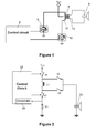
- the driver comprises a control circuit 2 and a transformer 4 comprising a primary winding 12 on the driver side and on the speaker side a secondary winding 14 connected in parallel with the piezoelectric speaker 6.
- the control circuit 2 controls a couple of switching means 8 and 10 for alternatively increasing and decreasing voltage across the primary winding 12 and transferring the stored energy to the secondary winding 14 and then to the speaker 6.
- the supply voltage V BAT is connected to an appropriate portion of the primary winding 12.
- This kind of driver requires big and heavy transformer and did not allow to control or stabilize the sound pressure level, because the driver's output voltage is set by the transformer ratio of turns and the supply voltage V BAT .
- One goal of the present invention is to overcome the aforecited drawbacks by providing an alarm sounder using a piezoelectric speaker driver with sound pressure level control.
- the invention concerns an alarm sounder comprising a piezoelectric speaker to generate an alarm sound controlled by a driver comprising a control circuit connected to switching means for alternatively increasing and decreasing energy across a winding coupled to the piezoelectric speaker, characterized in that the driver comprises means for stabilizing the piezoelectric voltage. Stabilization of the piezoelectric voltage allows controlling the sound pressure level.
- the means for stabilizing the piezoelectric voltage includes means for limiting the energy stored in the winding to a predefined level and means for transferring said predefined level of energy directly from the winding to the piezoelectric speaker.
- Such stabilizing means guaranties that energy stored in the winding is predefined, advantageously constant, and independent from the supply voltage.
- the driver's output voltage is neither set by the winding ratio of turns nor the supply voltage. Transfer of a predefined portion of energy to the piezoelectric speaker allows stabilization of the piezoelectric voltage and therefore control of its sound pressure level.
- the limiting means comprises a comparator which monitors the winding current with a predetermined threshold so as to limit energy storage to the predefined level.
- Current monitoring allows storing the required portion of energy within the winding.
- one terminal of the winding is connected to ground through a resistive element and the predetermined threshold is set by the voltage drop across the resistive element and a comparator reference voltage.
- the transferring means includes a first, respectively a second, switch connected between one, respectively the other, winding terminals and a same terminal of the piezoelectric speaker, the other terminal of the piezoelectric speaker being connected to ground, and wherein both switches are alternatively switched on and off so as to transfer with opposite direction said predefined level of energy to the piezoelectric speaker.
- one winding terminal is connected to the supply voltage through a third switch and the other winding terminal is connected to ground through a fourth switch, the control circuit being adapted for switching on simultaneously both the third and fourth switches to store energy within the winding and for alternatively switching off one of the two switches when the predefined level of energy is stored so as to transfer energy to the piezoelectric speaker.
- the driver comprises a couple of windings connected in series and wherein the common terminal of both windings is connected to both terminals of the piezoelectric speaker through two switches and each extreme winding terminal controls one of the two switches so as to be alternatively switched on and off to transfer with opposite direction said predefined level of stored energy in either one or the other of the two inductors to the piezoelectric speaker.
- the basic principle of the invention is to make a universal piezoelectric speaker driver with sound pressure level (SPL) control.
- SPL sound pressure level
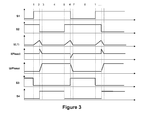
- the alarm sounder comprises a piezoelectric speaker 20 able to generate an alarm sound and controlled by a driver comprising a control circuit 22 connected to a couple of switching means S1, S2 for alternatively increasing and decreasing energy across a winding L1 coupled to the piezoelectric speaker 20.
- One winding terminal T 1 is connected to the supply voltage V SAT through switch S1 while the other winding terminal T 2 is grounded through switch S2.
- a resistive element R1 is connected between switch S2 and ground through in order to determine the threshold of energy to be stored in the winding by the voltage drop across the resistive element.
- the control circuit 22 is adapted for switching on and off both switches S1 and S2 to store energy within the winding L1.
- the driver further includes a comparator 24 which monitors the winding current with a predetermined threshold so as to limit energy storage to the predefined level. It furthermore includes a switch S3 connected between terminal T 1 of the winding and the driver's output connected to terminal T s of the speaker 20 and a switch S4 connected between the other terminal T 2 of the winding and the driver's output T s so as to be able to transfer with opposite direction the predefined level of energy to the piezoelectric speaker, which is seen as a capacitance.
- the winding current is monitored by the comparator 24 and is always switched off at the same threshold based on equation (1) which guaranties that the energy stored in winding is constant and independent of the supply voltage.
- the piezoelectric speaker voltage is also constant which is derivable from equation (3).
- the comparator threshold can be set by the controller circuit so that the sound pressure level (SPL) may be changed as needed; e.g. end of line calibration, SPL level adjustment for different customers, reduced SPL level when the driver is powered from internal battery or for warning / indication signals.
- SPL sound pressure level
- step 1 both switches S1 and S2 are closed, i.e. switched on, so that the winding current in L1 is rising.
- step 2 when the winding current reaches a threshold level set by the voltage drop in the resistive element R1 and by the comparator reference voltage, switch S2 is opened, i.e. switched off, so that the voltage across the winding becomes positive which causes to close (i.e. switch on) switch S4 and to transfer the energy to the piezoelectric speaker.
- step 3 when energy is transferred, in the given example the piezoelectric voltage is positive.
- Step 4 represents a break until the next cycle occurs.
- step 5 switches S1 and S2 are closed (switched on) and the winding current is rising again.
- step 6 when the winding current reaches the threshold level, switch S1 is open (switched off). This time, the voltage across the winding becomes negative which causes to close switch S3 and thus to transfer energy to the speaker.
- step 7 when energy is transferred, the piezoelectric voltage is then negative.
- Step 8 represents a break until next cycle corresponding to step 1.
- FIG. 4 illustrates a detailed electrical schematic of the alarm sounder according to an embodiment of the invention.
- the control circuit sends through OUT_H and OUT_L signals switching commands to the control terminals of switches S1 and S2, which are preferably made in MOS technology.
- One current terminal of the switch S1 is connected to the supply circuit and the other current terminal is connected to one terminal T 1 of the winding.
- One current terminal of the switch S2 is connected to ground via a resistor R9 and the other current terminal is connected to another terminal T 2 of the winding.
- the winding terminals T 1 and T 2 are respectively connected to one current terminal of a switch S3, respectively S4.
- the switching off of one switch S1 or S2 will cause the transfer of energy from the winding to the speaker represented with a capacitance. Indeed, when the potential at one current terminal of either switch S3 or switch S4 exceeds the threshold voltage of the transistor of the corresponding switch then the switch is switched on so as to let the energy transfer from the winding to the speaker.
- a comparator In order to obtain a constant energy level stored in the winding, a comparator has one input connected to the resistive element, while the other input is connected to a comparator reference voltage determining the predefined level of energy that will be stored. The output of the comparator is fed back through the control signals OUT_H and OUT_L.
- Figure 5 illustrates a detailed electrical schematic of the alarm sounder according to another embodiment.
- the control circuit which outputs signals OUT H and OUT_L to the control terminals of MOS transistors S1 and S2.
- One current terminal of S1 is connected to the resistive element while the other current terminal is connected to one side of the winding.
- One current terminal of S2 is also connected to the resistive element while the other current terminal is connected to the other side of the winding.
- the winding is center-tapped so as to define an upper winding and a lower winding connected in series.
- the upper terminal T 1 is connected as already mentioned to one current terminal of switch S1 but also to the control terminal of a switch S3
- the central terminal T 3 is connected to one current terminal of S3 and also to one current terminal of a switch S4
- the lower terminal T 2 is connected, as already mentioned to one current terminal of S2, but also to the control terminal of S4.
Landscapes
- Engineering & Computer Science (AREA)
- Physics & Mathematics (AREA)
- Acoustics & Sound (AREA)
- Signal Processing (AREA)
- Mechanical Engineering (AREA)
- Piezo-Electric Transducers For Audible Bands (AREA)
Abstract
Description
- The present invention relates to an alarm sounder using a piezoelectric speaker to generate the alarm sound. Such an alarm sounder is more particularly used in automotive vehicle.
- Such an alarm sounder using piezoelectric speaker already exists. Indeed, it is known that the piezoelectric speaker has high efficiency, but it requires high voltage to generate high Sound Pressure Level (SPL). Currently to generate such high voltage the alarm sounders or sirens are using a driver based on a transformer. An example of such a driver is presented on schematic of
Figure 1 . - The driver comprises a
control circuit 2 and atransformer 4 comprising aprimary winding 12 on the driver side and on the speaker side asecondary winding 14 connected in parallel with thepiezoelectric speaker 6. Thecontrol circuit 2 controls a couple of switching means 8 and 10 for alternatively increasing and decreasing voltage across theprimary winding 12 and transferring the stored energy to thesecondary winding 14 and then to thespeaker 6. According to the desired voltage level for energizing the speaker, the supply voltage VBAT is connected to an appropriate portion of theprimary winding 12. - This kind of driver requires big and heavy transformer and did not allow to control or stabilize the sound pressure level, because the driver's output voltage is set by the transformer ratio of turns and the supply voltage VBAT.
- One goal of the present invention is to overcome the aforecited drawbacks by providing an alarm sounder using a piezoelectric speaker driver with sound pressure level control.
- For that purpose, according to a first aspect, the invention concerns an alarm sounder comprising a piezoelectric speaker to generate an alarm sound controlled by a driver comprising a control circuit connected to switching means for alternatively increasing and decreasing energy across a winding coupled to the piezoelectric speaker, characterized in that the driver comprises means for stabilizing the piezoelectric voltage. Stabilization of the piezoelectric voltage allows controlling the sound pressure level.
- According to an advantageous embodiment, the means for stabilizing the piezoelectric voltage includes means for limiting the energy stored in the winding to a predefined level and means for transferring said predefined level of energy directly from the winding to the piezoelectric speaker. Such stabilizing means guaranties that energy stored in the winding is predefined, advantageously constant, and independent from the supply voltage. Thus, the driver's output voltage is neither set by the winding ratio of turns nor the supply voltage. Transfer of a predefined portion of energy to the piezoelectric speaker allows stabilization of the piezoelectric voltage and therefore control of its sound pressure level.
- According to another advantageous embodiment, the limiting means comprises a comparator which monitors the winding current with a predetermined threshold so as to limit energy storage to the predefined level. Current monitoring allows storing the required portion of energy within the winding. Advantageously, one terminal of the winding is connected to ground through a resistive element and the predetermined threshold is set by the voltage drop across the resistive element and a comparator reference voltage.
- According to another advantageous embodiment, the transferring means includes a first, respectively a second, switch connected between one, respectively the other, winding terminals and a same terminal of the piezoelectric speaker, the other terminal of the piezoelectric speaker being connected to ground, and wherein both switches are alternatively switched on and off so as to transfer with opposite direction said predefined level of energy to the piezoelectric speaker.
- According to another advantageous embodiment, one winding terminal is connected to the supply voltage through a third switch and the other winding terminal is connected to ground through a fourth switch, the control circuit being adapted for switching on simultaneously both the third and fourth switches to store energy within the winding and for alternatively switching off one of the two switches when the predefined level of energy is stored so as to transfer energy to the piezoelectric speaker.
- According to another advantageous embodiment, the driver comprises a couple of windings connected in series and wherein the common terminal of both windings is connected to both terminals of the piezoelectric speaker through two switches and each extreme winding terminal controls one of the two switches so as to be alternatively switched on and off to transfer with opposite direction said predefined level of stored energy in either one or the other of the two inductors to the piezoelectric speaker.
- Other features and advantages of the invention will appear upon reading the following description which refers to the annexed drawings in which:
-
Figure 1 , already described, is an electrical schematic illustration of an alarm sounder driver according to the prior art; -
Figure 2 illustrates a block diagram of an alarm sounder according to a preferred embodiment of the invention; -
Figure 3 represents a diagram showing the operation of the alarm sounder according to the embodiment ofFigure 2 ; -
Figure 4 illustrates a detailed electrical schematic of the alarm sounder according to a first variant; -
Figure 5 illustrates a detailed electrical schematic of the alarm sounder according to a second variant. - The basic principle of the invention is to make a universal piezoelectric speaker driver with sound pressure level (SPL) control. With reference now to
Figure 2 , a preferred embodiment of an alarm sounder according to the invention is shown. - The alarm sounder comprises a
piezoelectric speaker 20 able to generate an alarm sound and controlled by a driver comprising acontrol circuit 22 connected to a couple of switching means S1, S2 for alternatively increasing and decreasing energy across a winding L1 coupled to thepiezoelectric speaker 20. One winding terminal T1 is connected to the supply voltage VSAT through switch S1 while the other winding terminal T2 is grounded through switch S2. Preferably a resistive element R1 is connected between switch S2 and ground through in order to determine the threshold of energy to be stored in the winding by the voltage drop across the resistive element. Thecontrol circuit 22 is adapted for switching on and off both switches S1 and S2 to store energy within the winding L1. - For stabilizing the piezoelectric voltage, the driver further includes a
comparator 24 which monitors the winding current with a predetermined threshold so as to limit energy storage to the predefined level. It furthermore includes a switch S3 connected between terminal T1 of the winding and the driver's output connected to terminal Ts of thespeaker 20 and a switch S4 connected between the other terminal T2 of the winding and the driver's output Ts so as to be able to transfer with opposite direction the predefined level of energy to the piezoelectric speaker, which is seen as a capacitance. - The following formulas apply to the alarm sounder driver shown in
Figure 2 .


- During operation the winding current is monitored by the
comparator 24 and is always switched off at the same threshold based on equation (1) which guaranties that the energy stored in winding is constant and independent of the supply voltage. Thus when the winding energy is constant then the piezoelectric speaker voltage is also constant which is derivable from equation (3). The comparator threshold can be set by the controller circuit so that the sound pressure level (SPL) may be changed as needed; e.g. end of line calibration, SPL level adjustment for different customers, reduced SPL level when the driver is powered from internal battery or for warning / indication signals. - Based on equation (3), with the following parameters given as examples: peak current = 2A; L = 47uH; Cpiezo = 160nF; the driver is able to generate a voltage Vpiezo of 34V peak to peak.
- In order to be able to generate sound, the energy transferred to the speaker has to be transferred with opposite direction from one transfer to the other. This will be explained how more in detail with
Figure 3 . - Referring now to
Figure 3 , it will be described in more details the different steps of operation of the driver according to the above presented embodiment. - In
step 1, both switches S1 and S2 are closed, i.e. switched on, so that the winding current in L1 is rising. - In
step 2, when the winding current reaches a threshold level set by the voltage drop in the resistive element R1 and by the comparator reference voltage, switch S2 is opened, i.e. switched off, so that the voltage across the winding becomes positive which causes to close (i.e. switch on) switch S4 and to transfer the energy to the piezoelectric speaker. - In
step 3, when energy is transferred, in the given example the piezoelectric voltage is positive. -
Step 4 represents a break until the next cycle occurs. - In
step 5, switches S1 and S2 are closed (switched on) and the winding current is rising again. - In
step 6, when the winding current reaches the threshold level, switch S1 is open (switched off). This time, the voltage across the winding becomes negative which causes to close switch S3 and thus to transfer energy to the speaker. - In
step 7, when energy is transferred, the piezoelectric voltage is then negative. -
Step 8 represents a break until next cycle corresponding tostep 1. -
Figure 4 illustrates a detailed electrical schematic of the alarm sounder according to an embodiment of the invention. In this figure, the control circuit sends through OUT_H and OUT_L signals switching commands to the control terminals of switches S1 and S2, which are preferably made in MOS technology. One current terminal of the switch S1 is connected to the supply circuit and the other current terminal is connected to one terminal T1 of the winding. One current terminal of the switch S2 is connected to ground via a resistor R9 and the other current terminal is connected to another terminal T2 of the winding. - The winding terminals T1 and T2 are respectively connected to one current terminal of a switch S3, respectively S4. As explained in relation with
Figure 3 , the switching off of one switch S1 or S2 will cause the transfer of energy from the winding to the speaker represented with a capacitance. Indeed, when the potential at one current terminal of either switch S3 or switch S4 exceeds the threshold voltage of the transistor of the corresponding switch then the switch is switched on so as to let the energy transfer from the winding to the speaker. - In order to obtain a constant energy level stored in the winding, a comparator has one input connected to the resistive element, while the other input is connected to a comparator reference voltage determining the predefined level of energy that will be stored. The output of the comparator is fed back through the control signals OUT_H and OUT_L.
-
Figure 5 illustrates a detailed electrical schematic of the alarm sounder according to another embodiment. We find again the control circuit which outputs signals OUT H and OUT_L to the control terminals of MOS transistors S1 and S2. One current terminal of S1 is connected to the resistive element while the other current terminal is connected to one side of the winding. One current terminal of S2 is also connected to the resistive element while the other current terminal is connected to the other side of the winding. - In this embodiment, the winding is center-tapped so as to define an upper winding and a lower winding connected in series. With this specific winding configuration, the upper terminal T1 is connected as already mentioned to one current terminal of switch S1 but also to the control terminal of a switch S3, the central terminal T3 is connected to one current terminal of S3 and also to one current terminal of a switch S4 and the lower terminal T2 is connected, as already mentioned to one current terminal of S2, but also to the control terminal of S4.
- Thus, after both upper and lower windings have been charged, when one switch, either S1 or S2 is open (i.e. switched off) the corresponding switch S3 or S4 is closed (i.e. switched on) so as to transfer energy from the corresponding winding part, upper or lower, to the piezoelectric speaker.
- Having described the invention with regard to certain specific embodiments, it is to be understood that these embodiments are not meant as limitations of the invention. Indeed, various modifications, adaptations and/or combination between embodiments may become apparent to those skilled in the art without departing from the scope of the annexed claims.
Claims (7)
- An alarm sounder comprising a piezoelectric speaker (20) to generate an alarm sound controlled by a driver comprising a control circuit (22) connected to switching means (S1, S2) for alternatively increasing and decreasing energy across a winding (L1) coupled to the piezoelectric speaker, characterized in that the driver comprises means for stabilizing the piezoelectric voltage (Upiezo).
- An alarm sounder according to claim 1, wherein the means for stabilizing the piezoelectric voltage includes means for limiting (24) the energy stored in the winding to a predefined level and means for transferring (S3, S4) said predefined level of energy directly from the winding (L1) to the piezoelectric speaker (20).
- An alarm sounder according to claim 2, wherein the limiting means comprises a comparator which monitors the winding current (IL1) with a predetermined threshold so as to limit energy storage to the predefined level.
- An alarm sounder according to claim 3, wherein one terminal (T2) of the winding is connected to ground through a resistive element (R1) and wherein the predetermined threshold is set by the voltage drop across the resistive element and a comparator reference voltage.
- An alarm sounder according to any of claims 2 to 4, wherein the transferring means includes a first (S3), respectively a second (S4), switch connected between one, respectively the other, winding terminal (T1, T2) and a same terminal of the piezoelectric speaker, the other terminal of the piezoelectric speaker being connected to ground, and wherein both switches are alternatively switched on and off so as to transfer with opposite direction said predefined level of energy to the piezoelectric speaker.
- An alarm sounder according to any of claims 1 to 5, wherein one winding terminal (T1) is connected to the supply voltage through a third switch (S1) and the other winding terminal (T2) is connected to ground through a fourth switch (S2), the control circuit (22) being adapted for switching on simultaneously both the third and fourth switches to store energy within the winding (L1) and for alternatively switching off one of the two switches when the predefined level of energy is stored so as to transfer energy to the piezoelectric speaker (20).
- An alarm sounder according to claim 1 or 2, wherein the driver comprises a couple of windings (I1, L2) connected in series and wherein the common terminal (T3) of both windings is connected to both terminals of the piezoelectric speaker through two switches (S3, S4) and each extreme winding terminal (T1, T2) controls one of the two switches so as to be alternatively switched on and off.
Priority Applications (1)
| Application Number | Priority Date | Filing Date | Title |
|---|---|---|---|
| EP10152546A EP2355546A1 (en) | 2010-02-03 | 2010-02-03 | Piezo driver with sound pressure level control |
Applications Claiming Priority (1)
| Application Number | Priority Date | Filing Date | Title |
|---|---|---|---|
| EP10152546A EP2355546A1 (en) | 2010-02-03 | 2010-02-03 | Piezo driver with sound pressure level control |
Publications (1)
| Publication Number | Publication Date |
|---|---|
| EP2355546A1 true EP2355546A1 (en) | 2011-08-10 |
Family
ID=41818702
Family Applications (1)
| Application Number | Title | Priority Date | Filing Date |
|---|---|---|---|
| EP10152546A Withdrawn EP2355546A1 (en) | 2010-02-03 | 2010-02-03 | Piezo driver with sound pressure level control |
Country Status (1)
| Country | Link |
|---|---|
| EP (1) | EP2355546A1 (en) |
Citations (5)
| Publication number | Priority date | Publication date | Assignee | Title |
|---|---|---|---|---|
| GB2084427A (en) * | 1980-08-30 | 1982-04-07 | Moore Peter | Piezoelectric Sound Generator |
| US4496914A (en) * | 1981-11-13 | 1985-01-29 | Texas Instruments Incorporated | Piezo harn self-oscillating drive circuit |
| US5126589A (en) * | 1990-08-31 | 1992-06-30 | Siemens Pacesetter, Inc. | Piezoelectric driver using resonant energy transfer |
| US20070159507A1 (en) * | 2006-01-10 | 2007-07-12 | Seiko Epson Corporation | Piezoelectric actuator drive control method, piezoelectric actuator drive control apparatus, and electronic device |
| US20090038590A1 (en) * | 2007-08-09 | 2009-02-12 | Denso Corporation | Charge control unit and charge control system for fuel injection valve |
-
2010
- 2010-02-03 EP EP10152546A patent/EP2355546A1/en not_active Withdrawn
Patent Citations (5)
| Publication number | Priority date | Publication date | Assignee | Title |
|---|---|---|---|---|
| GB2084427A (en) * | 1980-08-30 | 1982-04-07 | Moore Peter | Piezoelectric Sound Generator |
| US4496914A (en) * | 1981-11-13 | 1985-01-29 | Texas Instruments Incorporated | Piezo harn self-oscillating drive circuit |
| US5126589A (en) * | 1990-08-31 | 1992-06-30 | Siemens Pacesetter, Inc. | Piezoelectric driver using resonant energy transfer |
| US20070159507A1 (en) * | 2006-01-10 | 2007-07-12 | Seiko Epson Corporation | Piezoelectric actuator drive control method, piezoelectric actuator drive control apparatus, and electronic device |
| US20090038590A1 (en) * | 2007-08-09 | 2009-02-12 | Denso Corporation | Charge control unit and charge control system for fuel injection valve |
Similar Documents
| Publication | Publication Date | Title |
|---|---|---|
| JP6534437B2 (en) | Charging system and method thereof | |
| JP4380747B2 (en) | Charger | |
| US10715047B1 (en) | Resonant power conversion device | |
| US8395489B2 (en) | Vehicle burglar alarm circuit | |
| JP2018170821A (en) | Control device for in-vehicle power supply system and in-vehicle power supply device | |
| JP5842483B2 (en) | Secondary battery power supply device and in-vehicle device | |
| JP2005295698A (en) | Power supply device for vehicle | |
| EP2355546A1 (en) | Piezo driver with sound pressure level control | |
| CN112187056A (en) | Power supply systems and DC-DC converters | |
| US6897766B2 (en) | Vibrator controlling circuit | |
| EP3982540B1 (en) | Switch control device, switch control method, and in-vehicle power supply system | |
| JP2013169051A (en) | Battery voltage equalization apparatus and method | |
| CN102629832B (en) | Switching power and image processing system | |
| JP2002189522A (en) | Regulator | |
| JP2008219973A (en) | Power unit for vehicle | |
| US6265854B1 (en) | DC/DC converter with battery low indicator | |
| JP4085794B2 (en) | Battery charger | |
| US20080191665A1 (en) | Charging circuit | |
| JP2599230B2 (en) | Charging device | |
| JP2005110374A (en) | Switching power supply | |
| JP7099376B2 (en) | Electronic control device for vehicles | |
| JPH09147921A (en) | Charging method for secondary battery | |
| JP3573847B2 (en) | Constant current charging device for large capacity capacitors | |
| CN214799443U (en) | Isolation drive circuit, protection device and power supply equipment of switch circuit | |
| JP2020145771A (en) | Charge/discharge controller and storage battery with charge/discharge controller |
Legal Events
| Date | Code | Title | Description |
|---|---|---|---|
| PUAI | Public reference made under article 153(3) epc to a published international application that has entered the european phase |
Free format text: ORIGINAL CODE: 0009012 |
|
| AK | Designated contracting states |
Kind code of ref document: A1 Designated state(s): AT BE BG CH CY CZ DE DK EE ES FI FR GB GR HR HU IE IS IT LI LT LU LV MC MK MT NL NO PL PT RO SE SI SK SM TR |
|
| AX | Request for extension of the european patent |
Extension state: AL BA RS |
|
| GRAP | Despatch of communication of intention to grant a patent |
Free format text: ORIGINAL CODE: EPIDOSNIGR1 |
|
| 17P | Request for examination filed |
Effective date: 20120210 |
|
| RIC1 | Information provided on ipc code assigned before grant |
Ipc: G10K 7/00 20060101ALI20120227BHEP Ipc: H01L 41/04 20060101ALI20120227BHEP Ipc: H04R 17/00 20060101AFI20120227BHEP |
|
| STAA | Information on the status of an ep patent application or granted ep patent |
Free format text: STATUS: THE APPLICATION IS DEEMED TO BE WITHDRAWN |
|
| 18D | Application deemed to be withdrawn |
Effective date: 20120731 |