EP2355304A2 - System to transmit and receive wireless power, terminal device, management server, and wireless power transmission apparatus - Google Patents
System to transmit and receive wireless power, terminal device, management server, and wireless power transmission apparatus Download PDFInfo
- Publication number
- EP2355304A2 EP2355304A2 EP10190252A EP10190252A EP2355304A2 EP 2355304 A2 EP2355304 A2 EP 2355304A2 EP 10190252 A EP10190252 A EP 10190252A EP 10190252 A EP10190252 A EP 10190252A EP 2355304 A2 EP2355304 A2 EP 2355304A2
- Authority
- EP
- European Patent Office
- Prior art keywords
- terminal device
- wireless power
- management server
- charge
- source resonator
- Prior art date
- Legal status (The legal status is an assumption and is not a legal conclusion. Google has not performed a legal analysis and makes no representation as to the accuracy of the status listed.)
- Withdrawn
Links
Images


Classifications
-
- G—PHYSICS
- G06—COMPUTING OR CALCULATING; COUNTING
- G06Q—INFORMATION AND COMMUNICATION TECHNOLOGY [ICT] SPECIALLY ADAPTED FOR ADMINISTRATIVE, COMMERCIAL, FINANCIAL, MANAGERIAL OR SUPERVISORY PURPOSES; SYSTEMS OR METHODS SPECIALLY ADAPTED FOR ADMINISTRATIVE, COMMERCIAL, FINANCIAL, MANAGERIAL OR SUPERVISORY PURPOSES, NOT OTHERWISE PROVIDED FOR
- G06Q50/00—Information and communication technology [ICT] specially adapted for implementation of business processes of specific business sectors, e.g. utilities or tourism
- G06Q50/06—Energy or water supply
-
- H—ELECTRICITY
- H02—GENERATION; CONVERSION OR DISTRIBUTION OF ELECTRIC POWER
- H02J—ELECTRIC POWER NETWORKS; CIRCUIT ARRANGEMENTS OR SYSTEMS FOR SUPPLYING OR DISTRIBUTING ELECTRIC POWER; SYSTEMS FOR STORING ELECTRIC ENERGY
- H02J50/00—Circuit arrangements or systems for wireless supply or distribution of electric power
- H02J50/10—Circuit arrangements or systems for wireless supply or distribution of electric power using inductive coupling
- H02J50/12—Circuit arrangements or systems for wireless supply or distribution of electric power using inductive coupling of the resonant type
-
- H—ELECTRICITY
- H02—GENERATION; CONVERSION OR DISTRIBUTION OF ELECTRIC POWER
- H02J—ELECTRIC POWER NETWORKS; CIRCUIT ARRANGEMENTS OR SYSTEMS FOR SUPPLYING OR DISTRIBUTING ELECTRIC POWER; SYSTEMS FOR STORING ELECTRIC ENERGY
- H02J50/00—Circuit arrangements or systems for wireless supply or distribution of electric power
- H02J50/40—Circuit arrangements or systems for wireless supply or distribution of electric power using two or more transmitting or receiving devices
-
- H—ELECTRICITY
- H02—GENERATION; CONVERSION OR DISTRIBUTION OF ELECTRIC POWER
- H02J—ELECTRIC POWER NETWORKS; CIRCUIT ARRANGEMENTS OR SYSTEMS FOR SUPPLYING OR DISTRIBUTING ELECTRIC POWER; SYSTEMS FOR STORING ELECTRIC ENERGY
- H02J50/00—Circuit arrangements or systems for wireless supply or distribution of electric power
- H02J50/80—Circuit arrangements or systems for wireless supply or distribution of electric power involving the exchange of data, concerning supply or distribution of electric power, between transmitting devices and receiving devices
-
- H—ELECTRICITY
- H02—GENERATION; CONVERSION OR DISTRIBUTION OF ELECTRIC POWER
- H02J—ELECTRIC POWER NETWORKS; CIRCUIT ARRANGEMENTS OR SYSTEMS FOR SUPPLYING OR DISTRIBUTING ELECTRIC POWER; SYSTEMS FOR STORING ELECTRIC ENERGY
- H02J50/00—Circuit arrangements or systems for wireless supply or distribution of electric power
- H02J50/90—Circuit arrangements or systems for wireless supply or distribution of electric power involving detection or optimisation of position, e.g. alignment
-
- H—ELECTRICITY
- H02—GENERATION; CONVERSION OR DISTRIBUTION OF ELECTRIC POWER
- H02J—ELECTRIC POWER NETWORKS; CIRCUIT ARRANGEMENTS OR SYSTEMS FOR SUPPLYING OR DISTRIBUTING ELECTRIC POWER; SYSTEMS FOR STORING ELECTRIC ENERGY
- H02J7/00—Circuit arrangements for charging or discharging batteries or for supplying loads from batteries
- H02J7/40—Circuit arrangements for charging or discharging batteries or for supplying loads from batteries characterised by the exchange of charge or discharge related data
- H02J7/47—Arrangements for checking compatibility or authentication between one component, e.g. a battery or a battery charger, and another component, e.g. a power source
-
- H—ELECTRICITY
- H02—GENERATION; CONVERSION OR DISTRIBUTION OF ELECTRIC POWER
- H02J—ELECTRIC POWER NETWORKS; CIRCUIT ARRANGEMENTS OR SYSTEMS FOR SUPPLYING OR DISTRIBUTING ELECTRIC POWER; SYSTEMS FOR STORING ELECTRIC ENERGY
- H02J7/00—Circuit arrangements for charging or discharging batteries or for supplying loads from batteries
- H02J7/80—Circuit arrangements for charging or discharging batteries or for supplying loads from batteries including monitoring or indicating arrangements
- H02J7/82—Control of state of charge [SOC]
Definitions
- This disclosure relates to a system to transmit and receive wireless power, a terminal device, a management server, and a wireless power transmission apparatus.
- Wireless power transmission technology denotes technology that may wirelessly transmit energy from a power source to an electronic device over distances of both a few millimeters, or short range transmission, and a few kilometers, or long range transmission.
- Short range transmission technology may transfer a relatively small output energy based on electromagnetic wave radiation.
- the transmission efficiency may be significantly deteriorated.
- a charge time may increase. If an output of a transmitter increases to decrease the charge time, it may cause harm to a human body. Accordingly, short range transmission technology may be inappropriate as wireless power transmission technology for wide use.
- Long range transmission technology generally employs an electromagnetic wave radiation process using 2.45 GHz or 5.8 GHz microwaves. Specifically, the long range transmission technology uses higher frequencies and, thus, may be dangerous to a human body, and transmission and reception of energy may be limited to a particular area.
- Exemplary embodiments of the present invention provide a system to transmit and receive wireless power, a terminal device, a management server, and a wireless power transmission apparatus that may decrease temporal or spatial constraints of wireless power transmission.
- An exemplary embodiment of the present invention discloses a terminal device chargeable by wireless power including a communication unit to receive frequency information over a wireless network used to receive the wireless power; a target resonator to synchronize with a resonant frequency with of the frequency information, and to receive the wireless power; and a charging unit to store energy that is output from the target resonator.
- An exemplary embodiment of the present invention discloses a management server for wireless power transmission, including a communication unit to receive a charge request message over a wireless network; and a control unit to control the communication unit to transmit frequency information used to transmit and receive the wireless power.
- An exemplary embodiment of the present invention discloses a wireless power transmission apparatus, including a communication unit to receive a charge request message; a control unit to perform an authentication process in response to the received charge request message, and to control the communication unit to transmit frequency information used for synchronization of a resonant frequency and transmission and reception of the wireless power; and a source resonator to transmit the wireless power.
- An exemplary embodiment of the present invention discloses a system to transmit and receive wireless power, including a terminal device to transmit a charge request message over a wireless network; a source resonator to transmit the wireless power to the terminal device based on frequency information used to synchronize a resonant frequency with the terminal device; and a management server to transmit the frequency information to the terminal device and the source resonator.
- An exemplary embodiment of the present invention discloses a method for charging wireless power in a device, the method including transmitting a charge request message; receiving frequency information; synchronizing a target resonator of the device with a resonant frequency of the frequency information; receiving the wireless power based on the resonant frequency; storing the wireless power in the device.
- An exemplary embodiment of the present invention discloses a method for controlling wireless power transmission, the method including receiving a charge request message over a wireless network; performing authentication based on the charge request message; determining if the wireless power transmission is possible based on the charge request message; transmitting frequency information including a resonant frequency at which the wireless power transmission is delivered over the wireless network; and determining a charge amount and a corresponding payment for the charge amount.
- FIG. 1 is a diagram illustrating a system to transmit and receive wireless power based on a wireless network according to an exemplary embodiment of the present invention.
- FIG. 2 is a block diagram illustrating a terminal device of FIG. 1 according to an exemplary embodiment of the present invention.
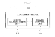
- FIG. 3 is a block diagram illustrating a management server of FIG. 1 according to an exemplary embodiment of the present invention.
- FIG. 4 is a block diagram illustrating a wireless power transmission apparatus of FIG. 1 according to an exemplary embodiment of the present invention
- FIG. 5 is a diagram illustrating a system to transmit and receive wireless power according to an exemplary embodiment of the present invention.
- FIG. 6 is a block diagram illustrating a wireless power transmission apparatus of FIG. 5 .
- FIG. 7 is a flowchart illustrating a method for charging wireless power at a terminal device according to an exemplary embodiment of the present invention.
- FIG. 8 is a flowchart illustrating a method for wireless power transmission of a management server according to an exemplary embodiment of the present invention.
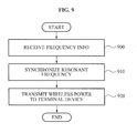
- FIG. 9 is a flowchart illustrating a method for transmitting wireless power according to an exemplary embodiment of the present invention.
- FIG. 10 is a flowchart illustrating a method for transmitting wireless power according to an exemplary embodiment of the present invention.
- FIG. 1 is a diagram illustrating a system to transmit and receive wireless power based on a wireless network according to an exemplary embodiment of the present invention.
- the system may use non-radial wireless energy transmission technology to generate a resonant frequency in a source resonator 400, to realize non-contact energy transmission by receiving wireless power in a terminal device 200, to manage energy transmission of a transmitter, and to control and manage energy transmission of the terminal device 200 disposed in an energy transmission area of the transmitter.
- a management server 300, the source resonator 400, and/or a base station 100 may correspond to the transmitter.
- the non-radial wireless power transmission may be performed according to a resonant characteristic between the source resonator 400 and a target resonator (not shown) included in the terminal device 200. Specifically, if the source resonator 400 and the target resonator resonate at a same frequency, magnetic field-based energy transmission may occur due to evanescent wave coupling. In this case, energy may correspond to wireless power or resonant power.
- the system to transmit and receive wireless power may include a base station 100, the terminal device 200, the management server 300, and the source resonator 400.
- the base station 100 may provide the terminal device 200 with a wireless communication service, and may provide a data through-path between the terminal device 200 and the management server 300 and a data through-path between the management server 300 and the source resonator 400. If a distance between the terminal device 200 and the management server 300 is included in wirelessly communicable range, the base station 100 may not be used.
- the terminal device 200 may wirelessly communicate with the base station 100 over the wireless network to provide a user with a service associated with wireless communication.
- the terminal device 200 may transmit a charge request message to the management server 300 over the wireless network, for example, if the terminal device 200 needs to be charged or has less than a full charge.
- the terminal device 200 may transmit authentication information and location information to the base station 100.
- the management server 300 may manage authentication of the terminal device 200 requesting the charge and also manage a payment for the charge. If the charge request message is received, the management server 300 may transmit to the terminal device 200 and the source resonator 400 frequency information used to synchronize a resonant frequency between the terminal device 200 and the source resonator 400.
- the terminal device 200 may synchronize the resonant frequency based on frequency information received from the management server 300. If the resonant frequency is synchronized, the terminal device 200 may wait to receive the wireless power.
- the source resonator 400 may synchronize the resonant frequency based on frequency information received from the management server 300. If the resonant frequency is synchronized, the source resonator 400 may transmit the wireless power to the terminal device 200. Accordingly, the terminal device 200 may receive the wireless power to generate energy required for the charge and then perform the charge.
- FIG. 2 is a block diagram illustrating the terminal device 200 of FIG. 1 according to an exemplary embodiment of the present invention.
- the terminal device 200 may include a terminal communication unit 210, a terminal storage unit 220, a terminal control unit 230, a target resonator 240, and a charging unit 250.
- the terminal communication unit 210 may provide a wireless communication service over the wireless network.
- the terminal communication unit 210 may transmit a charge request message to the management server 300. If the terminal device 200 provides the wireless communication service via the base station 100 located in the wireless network, information may be transmitted and received via the base station 100.
- the terminal communication unit 210 may receive from the management server 300 a message indicating that the management server 300 accepts the charge request, and may transmit an acknowledgement (ACK) to the management server 300.
- the terminal communication unit 210 may receive, from the management server 300 over the wireless network and the base station 100, frequency information used to receive the wireless power, and may transfer the received frequency information to the terminal control unit 230.
- Authentication information used for authentication of the terminal device 200 may be stored in the terminal storage unit 220.
- the authentication information may be used by the management server 300 to determine whether the terminal device 200 is authorized to receive a charge from the source resonator 400, and may include an authentication key assigned to the terminal device 200.
- the terminal control unit 230 may verify a charge amount of the terminal device 200.
- the terminal control unit 230 may control the terminal communication unit 210 to transmit a charge request message to the management server 300.
- the charge request message may include authentication information used for authentication of the terminal device 200 and location information of the terminal device 200.
- the location information of the terminal device 200 may be verified using a Global Positioning System (GPS) receiver embedded in the terminal device 200 or may be verified by the terminal device 200 in conjunction with the base station 100.
- GPS Global Positioning System
- the management server 300 may perform an authentication process based on the authentication information, and may determine whether the terminal device 200 is authorized to receive a charge from the source resonator 400 and whether it is possible to charge the terminal device 200 based on the location information. For example, if the terminal device 200 is located within a service range of the source resonator 400 transmitting the wireless power, the management server 300 may determine it is possible to charge the terminal device 200. If it is possible to charge the terminal device 200, the management server 300 may transmit, to the terminal communication unit 210, a message indicating that the management server 300 accepts the charge request.
- the service range denotes a maximum range in which the wireless power is transmittable, that is, a wireless charge serving area.
- the terminal control unit 230 may control the terminal communication unit 210 to transmit to the management server 300 the acknowledgement (ACK) in response to the acceptance.
- the management server 300 receiving the ACK may transmit to the terminal communication unit 210 and the source resonator 400 frequency information used to form the resonant frequency.
- the frequency information corresponds to resonant frequency information used to synchronize frequencies of the target resonator 240 and the source resonator 400.
- the terminal control unit 230 may form and synchronize the resonant frequency by controlling a resonant circuit of the target resonator 240 based on the received frequency information. If the resonant frequency between the target resonator 240 and the source resonator 400 is synchronized, the source resonator 400 may wirelessly transmit to the target resonator 240 power used to charge the terminal device 200.
- the target resonator 240 may form and synchronize the resonant frequency with the source resonator 400 based on the received frequency information, and may receive the wireless power from the source resonator 400 using the resonant frequency.
- the source resonator 400 may be configured as a wireless power transmission apparatus of FIG. 4 and, thus, the like reference numeral 400 will be used to describe the wireless power transmission apparatus of FIG. 4 .
- the charging unit 250 may charge or store energy that is output from the target resonator 240.
- the charging unit 250 may include a rectifier 251 and a charger 253.
- the rectifier 251 may rectify an output signal of the target resonator 240, and the charger 253 may store an output voltage of the rectifier 251 whereby a charging process may be initiated.
- the charging unit 250 may be a battery.
- the terminal control unit 230 may periodically verify a charge amount of charged energy and report the verified charge amount to the management server 300. If the charge is completed, the terminal control unit 230 may report a total amount of charge received in the terminal device 200 and that the charge is completed to the management server 300. The management server 300 may determine a payment based on the reported charge amount. The determined payment may be imposed upon the terminal device 200 or the source resonator 400.
- the terminal control unit 230 may control the terminal communication unit 210 to retransmit the charge request message to the management server 300.
- the management server 300 may retransmit frequency information used for synchronization of the resonant frequency to the terminal communication unit 210 and the source resonator 400.
- FIG. 3 is a block diagram illustrating the management server 300 of FIG. 1 according to an exemplary embodiment of the present invention.
- the management server 300 may include a server communication unit 310 and a server control unit 320.
- the server communication unit 310 may receive a charge request message from the terminal device 200 over the wireless network.
- the server communication unit 310 may transmit, to the terminal device 200, a message indicating that the charge request is accepted.
- the server communication unit 310 may receive, from the terminal device 200, ACK in response to the message.
- the ACK indicates that a charge preparation is completed.
- the server communication unit 310 may transmit, to the terminal device 200 and the source resonator 400, information used for synchronization of the resonant frequency.
- the server communication unit 310 may transmit frequency information to the terminal device 200 and the source resonator 400 over the wireless network and the base station 100.
- the server control unit 320 may determine whether it is possible to charge the terminal device 200 based on authentication information and location information received from the terminal device 200.
- the server control unit 320 may determine whether it is possible to charge the terminal device 200 based on service range information of the source resonator 400 and location information of the terminal device 200.
- the server control unit 320 may control the server communication unit 310 to transmit, to the terminal device 200 and the source resonator 400, frequency information used if the wireless power is transmitted from the source resonator 400 and received by the terminal device 200.
- the server control unit 320 may perform an authentication process of the terminal device 200 based on authentication information included in the charge request message, and may determine whether the terminal device 200 is located within the service range of the source resonator 400.
- the server control unit 320 stores, determines, or receives the service range of the source resonator 400 and thus may determine whether the terminal device 200 is located within the service range based on location information of the terminal device 200. If the terminal device 200 is located within the service range, the server control unit 320 may determine it is possible to charge the terminal device 200, and may transmit a message indicating that the charge request is accepted to the terminal device 200.
- the server control unit 320 may control the server communication unit 310 to transmit frequency information to the terminal device 200 and the source resonator 400.
- the terminal device 200 and the source resonator 400 may synchronize the resonant frequency based on the frequency information.
- the server control unit 320 may control a transmission output magnitude of resonant frequency by gathering information associated with the terminal device 200.
- the gathered information may include charge information, for example, a charge progress state reported from the terminal device 200, and a distance between the terminal device 200 and the source resonator 400. For example, if the distance between the terminal device 200 and the source resonator 400 increases, or if a charging speed decreases, the server control unit 320 may control the charge to be more quickly completed by increasing the transmission output magnitude.
- the server communication unit 310 may receive again the charge request message from the terminal device 200.
- the server control unit 320 may determine again whether it is possible to authenticate and charge the terminal device 200, and may retransmit frequency information to the terminal device 200 and the source resonator 400.
- the server control unit 320 may impose a payment upon an owner of the terminal device 200 or the source resonator 400 based on a total amount of charge reported from the terminal device 200.
- the server control unit 320 may transmit, to the source resonator 400 and the plurality of terminal devices, different frequency information used for synchronization of resonant frequency.
- a different resonant frequency channel may be formed between the source resonator 400 and each of the terminal devices based on the different frequency information and thus each of the terminal devices may be independently charged.
- the server control unit 320 may provide an authentication key to a terminal device having a relatively high priority among the plurality of terminal devices so that the terminal device receiving the authentication key may receive the wireless power from the source resonator 400.
- the server control unit 320 may transmit the frequency information to the terminal device receiving the authentication key. Accordingly, a resonant frequency may be formed between the corresponding terminal device and the source resonator 400. If completion of the charge is reported from the corresponding terminal device, the server control unit 320 may provide the authentication key to a terminal device having a second high priority, and perform the aforementioned operation.
- the server control unit 320 may report to the terminal device 200 that the charge is impossible, that is, it is impossible to charge the terminal device 200.
- the server control unit 200 may also report to the terminal device 200 reasons why the charge is impossible. The reasons may include, for example, an authentication failure, a payment fault, deterioration in a communication environment, and the like.
- FIG. 4 is a block diagram illustrating a wireless power transmission apparatus 400 according to an exemplary embodiment of the present invention.
- the wireless power transmission apparatus 400 may correspond to the source resonator 400 of FIG. 1 and/or, as described above, the management server 300 and/or the base station 100.
- the wireless power transmission apparatus 400 may include a resonator communication unit 410, a resonator control unit 420, and a source resonator 430.
- the resonator communication unit 410 may receive frequency information used to form and synchronize a resonant frequency from the management server 300 over the wireless network and the base station 100.
- the resonator control unit 420 may control a resonant circuit of the source resonator 400 to synchronize the resonant frequency based on the received frequency information. For example, the resonator control unit 420 may adjust inductance and capacitance of the source resonator 430 for synchronization of the resonant frequency.
- the source resonator 430 may transmit to the target resonator 240 of the terminal device 200 wireless power used for charging of the terminal device 200 using the resonant frequency.
- FIG. 5 is a diagram illustrating a system to transmit and receive wireless power according to an exemplary embodiment of the present invention.
- FIG. 6 is a block diagram illustrating a wireless power transmission apparatus 600 of FIG. 5 .
- the system to transmit and receive the wireless power may include a terminal device 500 and the wireless power transmission apparatus 600.
- the terminal device 500 may perform wireless communication over a wireless network and provide a user with a service associated with the wireless communication.
- the terminal 500 may transmit a charge request message to the wireless power transmission apparatus 600 over the wireless network.
- a resonator control unit 620 may determine whether it is possible to charge the terminal device 500, and may manage authentication of the terminal device 500 requesting the charge and a payment for the charge. If authentication information of the terminal device 500 is included in a stored authentication list, the resonator control unit 620 may determine the corresponding authentication as an authentication success; however, the authentication is not limited thereto such that the resonator control unit 620 may receive corresponding authentication information from an external source.
- the resonator control unit 620 may control the resonator communication unit 610 to transmit, to the terminal device 500, frequency information used for the terminal device 500.
- the frequency information may be transmitted over the wireless network.
- the resonator control unit 620 may control a resonant circuit of a source resonator 630 for synchronization of a resonant frequency between a target resonator 510 and the source resonator 630. If the resonant frequency with the terminal device 500 is synchronized, the source resonator 630 may transmit the wireless power to the target resonator 510.
- the terminal device 500 may synchronize the resonant frequency based on frequency information received from the wireless power transmission apparatus 600. If the resonant frequency is synchronized, the terminal device 500 may receive the wireless power from the wireless power transmission apparatus 600. Accordingly, the terminal device 500 may generate energy required for the charge, and then perform the charge.
- the resonator control unit 620 may impose a payment for the charge upon the terminal device 500 before, during, or after transmitting the wireless power.
- FIG. 7 is a flowchart illustrating a method for charging wireless power at a terminal device according to an exemplary embodiment of the present invention. The method may be performed by the terminal device 200.
- the terminal control unit 230 may control the terminal communication unit 210 to transmit a charge request message to the management server 300 in operation 700.
- the charge request message denotes a message requesting charge, and may include authentication information and location information of the terminal device 200.
- the terminal communication unit 210 may receive from the management server 300 a message informing about a charge acceptance and inquiring about a charge initiation.
- the terminal control unit 230 may control the terminal communication unit 210 to transmit to the management server 300 acknowledgement (ACK) in response to the message.
- ACK acknowledgement
- the terminal communication unit 210 may receive from the management server 300 frequency information used to receive a resonant frequency.
- the frequency information may include resonant frequency information used to synchronize frequencies between the target resonator 240 and the source resonator 400.
- the terminal control unit 230 may synchronize the resonant frequency by controlling a resonant circuit of the target resonator 240 based on the received frequency information.
- the target resonator 240 may receive the wireless power from the source resonator 400.
- the charging unit 250 may store energy, that is, the wireless power that is output from the target resonator 240. While the wireless power is being charged, the terminal control unit 230 may periodically verify a charge state, that is, a charge amount, and may report the verified charge amount to the management server 300.
- the terminal control unit 230 may control the terminal communication unit 210 to retransmit the charge request message to the management server 300 in operation 780.
- the terminal control unit 230 may report a total amount of charge and a completion of the charge to the management sever 300 in operation 790.
- the management server 300 may determine a payment based on the reported charge amount. The determined payment may be imposed upon the terminal device 200 or the source resonator 400.
- FIG. 8 is a flowchart illustrating a method for wireless power transmission of a management server according to an exemplary embodiment of the present invention. The method may be performed by the management server 300.
- the server communication unit 310 may receive a charge request message from the terminal device 200 over a wireless network.
- the server control unit 320 may perform authentication based on authentication information included in the charge request message.
- the server control unit 320 may determine whether it is possible to charge the terminal device 200 based on location information received in the charge request message. If it is possible to charge the terminal device 200 as a result of the determination in operation 820, the server control unit 320 may control the server communication unit 310 to transmit to the terminal device 200 a message informing about a charge acceptance and inquiring about a charge initiation, and may receive from the terminal device 200 the acknowledgement (ACK) in response to the message in operation 830.
- ACK acknowledgement
- the server control unit 320 may control the server communication unit 310 to transmit to the terminal device 200 and the source resonator 400 frequency information used for synchronization of the resonant frequency.
- the server communication unit 310 may receive a charge state of the terminal device 200 from the terminal device 200 over the wireless network. If charging of the terminal device 200 is completed or terminated in operation 860, the server communication unit 310 may receive from the terminal device 200 a report about completion of the charge and a total amount of charge received. If the charge service is a paid service, the server control unit 320 may determine a payment to be imposed upon an owner of the terminal device 200 or the source resonator 400 based on the received total amount of charge in operation 870.
- the server control unit 320 may control the server communication unit 310 to report to the terminal device 200 that it is impossible to charge the terminal device 200 in operation 880.
- FIG. 9 is a flowchart illustrating a method for transmitting wireless power according to an exemplary embodiment of the present invention. The method may be performed by the wireless power transmission apparatus 400.
- the resonator communication unit 410 may receive frequency information used to form and synchronize a resonant frequency from the management server 300 over a wireless network.
- the resonator control unit 420 may synchronize the resonant frequency by controlling a resonant circuit of the source resonator 400 based on the received frequency information.
- the source resonator 430 may transmit the wireless power to the terminal device 200.
- FIG. 10 is a flowchart illustrating a method for transmitting wireless power according to an exemplary embodiment of the present invention. The method may be performed by the wireless power transmission apparatus 600.
- the resonator communication unit 610 may receive a charge request message from the terminal device 500 over a wireless network.
- the resonator control unit 620 may perform authentication based on authentication information included in the charge request message.
- the resonator control unit 620 may determine whether it is possible to charge the terminal device 200 based on location information received in the charge request. If it is possible to charge the terminal device 200 as a result of the determination in operation 1020, the resonator control unit 620 may control the resonator communication unit 610 to transmit a message informing about a charge acceptance and inquiring about a charge initiation to the terminal device 500, and may receive ACK in response to the message from the terminal device 500 in operation 1030.
- the resonator control unit 620 may control the resonator communication unit 610 to transmit frequency information used to form and synchronize the resonant frequency to the terminal device 500.
- the resonant control unit 620 may control a resonant circuit of the source resonator 630 for synchronization of the resonant frequency between the target resonator 510 and the source resonator 630.
- the source resonator 630 may transmit the wireless power to the target resonator 510 in operation 1060. Accordingly, charging of the terminal device 500 may be initiated.
- the resonator communication unit 610 may receive a charge state of the terminal device 500 from the terminal device 500 over the wireless network.
- the resonator communication unit 610 may receive, from the terminal device 500, a report about completion of the charge and the total amount of charge transmitted to or received by the terminal device 500.
- the resonator control unit 620 may determine a payment to be imposed upon the terminal device 500 based on the total amount of charge transmitted to or received by the terminal device 500 in operation 1090.
- the resonator control unit 620 may report to the terminal device 500 that it is impossible to charge the terminal device 500 in operation 1095.
- a management server or a source resonator may determine whether it is possible to charge the terminal device, and initiation and termination of the charge based on one or more of a charge request of the terminal device, a battery state, location information, authentication information, and the like.
- a service provider may employ a wireless energy transmission service as a business model using payment information.
- a user of the terminal device may receive a charge service in a wireless charge service area.
- the exemplary embodiments according to the present invention may be recorded in computer-readable media including program instructions to implement various operations embodied by a computer.
- the media may also include, alone or in combination with the program instructions, data files, data structures, and the like.
- the media and program instructions may be those specially designed and constructed for the purposes of the present invention, or they may be of the kind well-known and available to those having skill in the computer software arts.
- Examples of computer-readable media include magnetic media such as hard disks, floppy disks, and magnetic tape; optical media such as CD ROM disks and DVD; magneto-optical media such as floptical disks; and hardware devices that are specially configured to store and perform program instructions, such as read-only memory (ROM), random access memory (RAM), flash memory, and the like, and combinations thereof.
- Examples of program instructions include both machine code, such as produced by a compiler, and files containing higher level code that may be executed by the computer using an interpreter.
- the described hardware devices may be configured to act as one or more software modules in order to perform the operations of the above-described embodiments of the present invention.
- a system to transmit and receive wireless power may use non-radial wireless energy transmission technology to generate a resonant frequency in resonators and charge a device.
- the terminal device may receive the wireless power to perform charging by non-contact energy transmission.
Landscapes
- Engineering & Computer Science (AREA)
- Power Engineering (AREA)
- Computer Networks & Wireless Communication (AREA)
- Business, Economics & Management (AREA)
- Health & Medical Sciences (AREA)
- Economics (AREA)
- General Health & Medical Sciences (AREA)
- Water Supply & Treatment (AREA)
- Public Health (AREA)
- Human Resources & Organizations (AREA)
- Marketing (AREA)
- Primary Health Care (AREA)
- Strategic Management (AREA)
- Tourism & Hospitality (AREA)
- Physics & Mathematics (AREA)
- General Business, Economics & Management (AREA)
- General Physics & Mathematics (AREA)
- Theoretical Computer Science (AREA)
- Charge And Discharge Circuits For Batteries Or The Like (AREA)
Abstract
A system to transmit and receive wireless power, a terminal device (200), a management server (300), and a wireless power transmission apparatus may use non-radial wireless energy transmission technology to generate a resonant frequency in resonators and charge a device. The terminal device may receive the wireless power to perform charging by non-contact energy transmission.
Description
- This application claims priority from and the benefit of Korean Patent Application No.
10-2010-0007839, filed on January 28, 2010 - 1. Field
- This disclosure relates to a system to transmit and receive wireless power, a terminal device, a management server, and a wireless power transmission apparatus.
- 2. Discussion of the Background
- Wireless power transmission technology denotes technology that may wirelessly transmit energy from a power source to an electronic device over distances of both a few millimeters, or short range transmission, and a few kilometers, or long range transmission.
- Short range transmission technology may transfer a relatively small output energy based on electromagnetic wave radiation. However, due to omni-directionality, that is, a characteristic of electromagnetic wave radiation, the transmission efficiency may be significantly deteriorated. In the case of a device using high power, a charge time may increase. If an output of a transmitter increases to decrease the charge time, it may cause harm to a human body. Accordingly, short range transmission technology may be inappropriate as wireless power transmission technology for wide use.
- Long range transmission technology generally employs an electromagnetic wave radiation process using 2.45 GHz or 5.8 GHz microwaves. Specifically, the long range transmission technology uses higher frequencies and, thus, may be dangerous to a human body, and transmission and reception of energy may be limited to a particular area.
- Exemplary embodiments of the present invention provide a system to transmit and receive wireless power, a terminal device, a management server, and a wireless power transmission apparatus that may decrease temporal or spatial constraints of wireless power transmission.
- Additional features of the invention will be set forth in the description which follows, and in part will be apparent from the description, or may be learned by practice of the invention.
- An exemplary embodiment of the present invention discloses a terminal device chargeable by wireless power including a communication unit to receive frequency information over a wireless network used to receive the wireless power; a target resonator to synchronize with a resonant frequency with of the frequency information, and to receive the wireless power; and a charging unit to store energy that is output from the target resonator.
- An exemplary embodiment of the present invention discloses a management server for wireless power transmission, including a communication unit to receive a charge request message over a wireless network; and a control unit to control the communication unit to transmit frequency information used to transmit and receive the wireless power.
- An exemplary embodiment of the present invention discloses a wireless power transmission apparatus, including a communication unit to receive a charge request message; a control unit to perform an authentication process in response to the received charge request message, and to control the communication unit to transmit frequency information used for synchronization of a resonant frequency and transmission and reception of the wireless power; and a source resonator to transmit the wireless power.
- An exemplary embodiment of the present invention discloses a system to transmit and receive wireless power, including a terminal device to transmit a charge request message over a wireless network; a source resonator to transmit the wireless power to the terminal device based on frequency information used to synchronize a resonant frequency with the terminal device; and a management server to transmit the frequency information to the terminal device and the source resonator.
- An exemplary embodiment of the present invention discloses a method for charging wireless power in a device, the method including transmitting a charge request message; receiving frequency information; synchronizing a target resonator of the device with a resonant frequency of the frequency information; receiving the wireless power based on the resonant frequency; storing the wireless power in the device.
- An exemplary embodiment of the present invention discloses a method for controlling wireless power transmission, the method including receiving a charge request message over a wireless network; performing authentication based on the charge request message; determining if the wireless power transmission is possible based on the charge request message; transmitting frequency information including a resonant frequency at which the wireless power transmission is delivered over the wireless network; and determining a charge amount and a corresponding payment for the charge amount.
- It is to be understood that both the foregoing general description and the following detailed description are exemplary and explanatory and are intended to provide further explanation of the invention as claimed
- The accompanying drawings, which are included to provide a further understanding of the invention and are incorporated in and constitute a part of this specification, illustrate embodiments of the invention, and together with the description serve to explain the principles of the invention.
-
FIG. 1 is a diagram illustrating a system to transmit and receive wireless power based on a wireless network according to an exemplary embodiment of the present invention. -
FIG. 2 is a block diagram illustrating a terminal device ofFIG. 1 according to an exemplary embodiment of the present invention. -
FIG. 3 is a block diagram illustrating a management server ofFIG. 1 according to an exemplary embodiment of the present invention. -
FIG. 4 is a block diagram illustrating a wireless power transmission apparatus ofFIG. 1 according to an exemplary embodiment of the present invention; -
FIG. 5 is a diagram illustrating a system to transmit and receive wireless power according to an exemplary embodiment of the present invention. -
FIG. 6 is a block diagram illustrating a wireless power transmission apparatus ofFIG. 5 . -
FIG. 7 is a flowchart illustrating a method for charging wireless power at a terminal device according to an exemplary embodiment of the present invention. -
FIG. 8 is a flowchart illustrating a method for wireless power transmission of a management server according to an exemplary embodiment of the present invention. -
FIG. 9 is a flowchart illustrating a method for transmitting wireless power according to an exemplary embodiment of the present invention. -
FIG. 10 is a flowchart illustrating a method for transmitting wireless power according to an exemplary embodiment of the present invention. - The invention is described more fully hereinafter with reference to the accompanying drawings, in which exemplary embodiments of the invention are shown. This invention may, however, be embodied in many different forms and should not be construed as limited to the exemplary embodiments set forth herein. Rather, these exemplary embodiments are provided so that this disclosure is thorough, and will fully convey the scope of the invention to those skilled in the art. In the drawings, the size and relative sizes of layers and regions may be exaggerated for clarity. Like reference numerals in the drawings denote like elements.
- It will be understood that when an element is referred to as being "connected to", "receives from", or "transmits to" another element, it can be directly connected to, received from, or transmitted to the other element, or intervening elements may be present.
-
FIG. 1 is a diagram illustrating a system to transmit and receive wireless power based on a wireless network according to an exemplary embodiment of the present invention. The system may use non-radial wireless energy transmission technology to generate a resonant frequency in asource resonator 400, to realize non-contact energy transmission by receiving wireless power in aterminal device 200, to manage energy transmission of a transmitter, and to control and manage energy transmission of theterminal device 200 disposed in an energy transmission area of the transmitter. Here, amanagement server 300, thesource resonator 400, and/or abase station 100 may correspond to the transmitter. - The non-radial wireless power transmission may be performed according to a resonant characteristic between the
source resonator 400 and a target resonator (not shown) included in theterminal device 200. Specifically, if thesource resonator 400 and the target resonator resonate at a same frequency, magnetic field-based energy transmission may occur due to evanescent wave coupling. In this case, energy may correspond to wireless power or resonant power. - Referring to
FIG. 1 , the system to transmit and receive wireless power may include abase station 100, theterminal device 200, themanagement server 300, and thesource resonator 400. - The
base station 100 may provide theterminal device 200 with a wireless communication service, and may provide a data through-path between theterminal device 200 and themanagement server 300 and a data through-path between themanagement server 300 and thesource resonator 400. If a distance between theterminal device 200 and themanagement server 300 is included in wirelessly communicable range, thebase station 100 may not be used. - The
terminal device 200 may wirelessly communicate with thebase station 100 over the wireless network to provide a user with a service associated with wireless communication. Theterminal device 200 may transmit a charge request message to themanagement server 300 over the wireless network, for example, if theterminal device 200 needs to be charged or has less than a full charge. Theterminal device 200 may transmit authentication information and location information to thebase station 100. - The
management server 300 may manage authentication of theterminal device 200 requesting the charge and also manage a payment for the charge. If the charge request message is received, themanagement server 300 may transmit to theterminal device 200 and thesource resonator 400 frequency information used to synchronize a resonant frequency between theterminal device 200 and thesource resonator 400. - The
terminal device 200 may synchronize the resonant frequency based on frequency information received from themanagement server 300. If the resonant frequency is synchronized, theterminal device 200 may wait to receive the wireless power. - The
source resonator 400 may synchronize the resonant frequency based on frequency information received from themanagement server 300. If the resonant frequency is synchronized, thesource resonator 400 may transmit the wireless power to theterminal device 200. Accordingly, theterminal device 200 may receive the wireless power to generate energy required for the charge and then perform the charge. -
FIG. 2 is a block diagram illustrating theterminal device 200 ofFIG. 1 according to an exemplary embodiment of the present invention. Referring toFIG. 2 , theterminal device 200 may include aterminal communication unit 210, aterminal storage unit 220, aterminal control unit 230, atarget resonator 240, and acharging unit 250. - The
terminal communication unit 210 may provide a wireless communication service over the wireless network. Theterminal communication unit 210 may transmit a charge request message to themanagement server 300. If theterminal device 200 provides the wireless communication service via thebase station 100 located in the wireless network, information may be transmitted and received via thebase station 100. - The
terminal communication unit 210 may receive from the management server 300 a message indicating that themanagement server 300 accepts the charge request, and may transmit an acknowledgement (ACK) to themanagement server 300. Theterminal communication unit 210 may receive, from themanagement server 300 over the wireless network and thebase station 100, frequency information used to receive the wireless power, and may transfer the received frequency information to theterminal control unit 230. - Authentication information used for authentication of the
terminal device 200 may be stored in theterminal storage unit 220. The authentication information may be used by themanagement server 300 to determine whether theterminal device 200 is authorized to receive a charge from thesource resonator 400, and may include an authentication key assigned to theterminal device 200. - The
terminal control unit 230 may verify a charge amount of theterminal device 200. Theterminal control unit 230 may control theterminal communication unit 210 to transmit a charge request message to themanagement server 300. The charge request message may include authentication information used for authentication of theterminal device 200 and location information of theterminal device 200. The location information of theterminal device 200 may be verified using a Global Positioning System (GPS) receiver embedded in theterminal device 200 or may be verified by theterminal device 200 in conjunction with thebase station 100. - If the
terminal communication unit 210 transmits the charge request message, themanagement server 300 may perform an authentication process based on the authentication information, and may determine whether theterminal device 200 is authorized to receive a charge from thesource resonator 400 and whether it is possible to charge theterminal device 200 based on the location information. For example, if theterminal device 200 is located within a service range of thesource resonator 400 transmitting the wireless power, themanagement server 300 may determine it is possible to charge theterminal device 200. If it is possible to charge theterminal device 200, themanagement server 300 may transmit, to theterminal communication unit 210, a message indicating that themanagement server 300 accepts the charge request. The service range denotes a maximum range in which the wireless power is transmittable, that is, a wireless charge serving area. - The
terminal control unit 230 may control theterminal communication unit 210 to transmit to themanagement server 300 the acknowledgement (ACK) in response to the acceptance. Themanagement server 300 receiving the ACK may transmit to theterminal communication unit 210 and thesource resonator 400 frequency information used to form the resonant frequency. - The frequency information corresponds to resonant frequency information used to synchronize frequencies of the
target resonator 240 and thesource resonator 400. Theterminal control unit 230 may form and synchronize the resonant frequency by controlling a resonant circuit of thetarget resonator 240 based on the received frequency information. If the resonant frequency between thetarget resonator 240 and thesource resonator 400 is synchronized, thesource resonator 400 may wirelessly transmit to thetarget resonator 240 power used to charge theterminal device 200. - As described above, the
target resonator 240 may form and synchronize the resonant frequency with thesource resonator 400 based on the received frequency information, and may receive the wireless power from thesource resonator 400 using the resonant frequency. Thesource resonator 400 may be configured as a wireless power transmission apparatus ofFIG. 4 and, thus, thelike reference numeral 400 will be used to describe the wireless power transmission apparatus ofFIG. 4 . - The charging
unit 250 may charge or store energy that is output from thetarget resonator 240. For this, the chargingunit 250 may include arectifier 251 and acharger 253. Therectifier 251 may rectify an output signal of thetarget resonator 240, and thecharger 253 may store an output voltage of therectifier 251 whereby a charging process may be initiated. The chargingunit 250 may be a battery. - The
terminal control unit 230 may periodically verify a charge amount of charged energy and report the verified charge amount to themanagement server 300. If the charge is completed, theterminal control unit 230 may report a total amount of charge received in theterminal device 200 and that the charge is completed to themanagement server 300. Themanagement server 300 may determine a payment based on the reported charge amount. The determined payment may be imposed upon theterminal device 200 or thesource resonator 400. - If the charging process is suspended prior to completion, the
terminal control unit 230 may control theterminal communication unit 210 to retransmit the charge request message to themanagement server 300. In response to the retransmitted charge request message, themanagement server 300 may retransmit frequency information used for synchronization of the resonant frequency to theterminal communication unit 210 and thesource resonator 400. -
FIG. 3 is a block diagram illustrating themanagement server 300 ofFIG. 1 according to an exemplary embodiment of the present invention. Referring toFIG. 3 , themanagement server 300 may include aserver communication unit 310 and aserver control unit 320. Theserver communication unit 310 may receive a charge request message from theterminal device 200 over the wireless network. Theserver communication unit 310 may transmit, to theterminal device 200, a message indicating that the charge request is accepted. And, theserver communication unit 310 may receive, from theterminal device 200, ACK in response to the message. The ACK indicates that a charge preparation is completed. Theserver communication unit 310 may transmit, to theterminal device 200 and thesource resonator 400, information used for synchronization of the resonant frequency. Theserver communication unit 310 may transmit frequency information to theterminal device 200 and thesource resonator 400 over the wireless network and thebase station 100. - The
server control unit 320 may determine whether it is possible to charge theterminal device 200 based on authentication information and location information received from theterminal device 200. Theserver control unit 320 may determine whether it is possible to charge theterminal device 200 based on service range information of thesource resonator 400 and location information of theterminal device 200. - In response to the received charge request message, the
server control unit 320 may control theserver communication unit 310 to transmit, to theterminal device 200 and thesource resonator 400, frequency information used if the wireless power is transmitted from thesource resonator 400 and received by theterminal device 200. - Specifically, the
server control unit 320 may perform an authentication process of theterminal device 200 based on authentication information included in the charge request message, and may determine whether theterminal device 200 is located within the service range of thesource resonator 400. Theserver control unit 320 stores, determines, or receives the service range of thesource resonator 400 and thus may determine whether theterminal device 200 is located within the service range based on location information of theterminal device 200. If theterminal device 200 is located within the service range, theserver control unit 320 may determine it is possible to charge theterminal device 200, and may transmit a message indicating that the charge request is accepted to theterminal device 200. - If the charge preparation of the
terminal device 200 is completed, theserver control unit 320 may control theserver communication unit 310 to transmit frequency information to theterminal device 200 and thesource resonator 400. Theterminal device 200 and thesource resonator 400 may synchronize the resonant frequency based on the frequency information. - While the
terminal device 200 receives the wireless power from thesource resonator 400, theserver control unit 320 may control a transmission output magnitude of resonant frequency by gathering information associated with theterminal device 200. The gathered information may include charge information, for example, a charge progress state reported from theterminal device 200, and a distance between theterminal device 200 and thesource resonator 400. For example, if the distance between theterminal device 200 and thesource resonator 400 increases, or if a charging speed decreases, theserver control unit 320 may control the charge to be more quickly completed by increasing the transmission output magnitude. - While charging of the
terminal device 200 is ongoing, theserver communication unit 310 may receive again the charge request message from theterminal device 200. Theserver control unit 320 may determine again whether it is possible to authenticate and charge theterminal device 200, and may retransmit frequency information to theterminal device 200 and thesource resonator 400. - If a charge service is a paid service, the
server control unit 320 may impose a payment upon an owner of theterminal device 200 or thesource resonator 400 based on a total amount of charge reported from theterminal device 200. - If a plurality of terminal devices (not shown) is located within the service range of the
source resonator 400 and requests a charge, theserver control unit 320 may transmit, to thesource resonator 400 and the plurality of terminal devices, different frequency information used for synchronization of resonant frequency. A different resonant frequency channel may be formed between thesource resonator 400 and each of the terminal devices based on the different frequency information and thus each of the terminal devices may be independently charged. - If the plurality of terminal devices is located within the service range of the
source resonator 400 and requests the charge, theserver control unit 320 may provide an authentication key to a terminal device having a relatively high priority among the plurality of terminal devices so that the terminal device receiving the authentication key may receive the wireless power from thesource resonator 400. Theserver control unit 320 may transmit the frequency information to the terminal device receiving the authentication key. Accordingly, a resonant frequency may be formed between the corresponding terminal device and thesource resonator 400. If completion of the charge is reported from the corresponding terminal device, theserver control unit 320 may provide the authentication key to a terminal device having a second high priority, and perform the aforementioned operation. - If it is impossible to charge the
terminal device 200 according to a determination of theserver control unit 320, theserver control unit 320 may report to theterminal device 200 that the charge is impossible, that is, it is impossible to charge theterminal device 200. Theserver control unit 200 may also report to theterminal device 200 reasons why the charge is impossible. The reasons may include, for example, an authentication failure, a payment fault, deterioration in a communication environment, and the like. -
FIG. 4 is a block diagram illustrating a wirelesspower transmission apparatus 400 according to an exemplary embodiment of the present invention. The wirelesspower transmission apparatus 400 may correspond to thesource resonator 400 ofFIG. 1 and/or, as described above, themanagement server 300 and/or thebase station 100. The wirelesspower transmission apparatus 400 may include aresonator communication unit 410, aresonator control unit 420, and asource resonator 430. - The
resonator communication unit 410 may receive frequency information used to form and synchronize a resonant frequency from themanagement server 300 over the wireless network and thebase station 100. - The
resonator control unit 420 may control a resonant circuit of thesource resonator 400 to synchronize the resonant frequency based on the received frequency information. For example, theresonator control unit 420 may adjust inductance and capacitance of thesource resonator 430 for synchronization of the resonant frequency. - If the resonant frequency between the
terminal device 200 and thesource resonator 430 is synchronized, thesource resonator 430 may transmit to thetarget resonator 240 of theterminal device 200 wireless power used for charging of theterminal device 200 using the resonant frequency. -
FIG. 5 is a diagram illustrating a system to transmit and receive wireless power according to an exemplary embodiment of the present invention.FIG. 6 is a block diagram illustrating a wirelesspower transmission apparatus 600 ofFIG. 5 . - Referring to
FIG. 5 andFIG. 6 , the system to transmit and receive the wireless power may include aterminal device 500 and the wirelesspower transmission apparatus 600. Theterminal device 500 may perform wireless communication over a wireless network and provide a user with a service associated with the wireless communication. The terminal 500 may transmit a charge request message to the wirelesspower transmission apparatus 600 over the wireless network. - If a
resonator communication unit 610 receives the charge request message from theterminal device 500, aresonator control unit 620 may determine whether it is possible to charge theterminal device 500, and may manage authentication of theterminal device 500 requesting the charge and a payment for the charge. If authentication information of theterminal device 500 is included in a stored authentication list, theresonator control unit 620 may determine the corresponding authentication as an authentication success; however, the authentication is not limited thereto such that theresonator control unit 620 may receive corresponding authentication information from an external source. - If it is possible to charge the
terminal device 500 as a result of the determination, theresonator control unit 620 may control theresonator communication unit 610 to transmit, to theterminal device 500, frequency information used for theterminal device 500. The frequency information may be transmitted over the wireless network. - The
resonator control unit 620 may control a resonant circuit of asource resonator 630 for synchronization of a resonant frequency between atarget resonator 510 and thesource resonator 630. If the resonant frequency with theterminal device 500 is synchronized, thesource resonator 630 may transmit the wireless power to thetarget resonator 510. - The
terminal device 500 may synchronize the resonant frequency based on frequency information received from the wirelesspower transmission apparatus 600. If the resonant frequency is synchronized, theterminal device 500 may receive the wireless power from the wirelesspower transmission apparatus 600. Accordingly, theterminal device 500 may generate energy required for the charge, and then perform the charge. - The
resonator control unit 620 may impose a payment for the charge upon theterminal device 500 before, during, or after transmitting the wireless power. -
FIG. 7 is a flowchart illustrating a method for charging wireless power at a terminal device according to an exemplary embodiment of the present invention. The method may be performed by theterminal device 200. - In
operation 700, if it is determined that theterminal device 200 needs to be charged, or if a charge request is received from a user, or if theterminal device 200 is charged less than a capacity or a threshold value, theterminal control unit 230 may control theterminal communication unit 210 to transmit a charge request message to themanagement server 300 inoperation 700. The charge request message denotes a message requesting charge, and may include authentication information and location information of theterminal device 200. - In
operation 710, theterminal communication unit 210 may receive from the management server 300 a message informing about a charge acceptance and inquiring about a charge initiation. - In
operation 720, theterminal control unit 230 may control theterminal communication unit 210 to transmit to themanagement server 300 acknowledgement (ACK) in response to the message. - In
operation 730, theterminal communication unit 210 may receive from themanagement server 300 frequency information used to receive a resonant frequency. The frequency information may include resonant frequency information used to synchronize frequencies between thetarget resonator 240 and thesource resonator 400. - In
operation 740, theterminal control unit 230 may synchronize the resonant frequency by controlling a resonant circuit of thetarget resonator 240 based on the received frequency information. - In
operation 750, if the resonant frequency between thetarget resonator 240 and thesource resonator 400 is synchronized, thetarget resonator 240 may receive the wireless power from thesource resonator 400. - In
operation 760, the chargingunit 250 may store energy, that is, the wireless power that is output from thetarget resonator 240. While the wireless power is being charged, theterminal control unit 230 may periodically verify a charge state, that is, a charge amount, and may report the verified charge amount to themanagement server 300. - If the charging operation is suspended prior to completion in
operation 770, theterminal control unit 230 may control theterminal communication unit 210 to retransmit the charge request message to themanagement server 300 inoperation 780. - Conversely, if the charging operation is completed, the
terminal control unit 230 may report a total amount of charge and a completion of the charge to the management sever 300 inoperation 790. Themanagement server 300 may determine a payment based on the reported charge amount. The determined payment may be imposed upon theterminal device 200 or thesource resonator 400. -
FIG. 8 is a flowchart illustrating a method for wireless power transmission of a management server according to an exemplary embodiment of the present invention. The method may be performed by themanagement server 300. - In
operation 800, theserver communication unit 310 may receive a charge request message from theterminal device 200 over a wireless network. - In
operation 810, theserver control unit 320 may perform authentication based on authentication information included in the charge request message. - In
operation 820, theserver control unit 320 may determine whether it is possible to charge theterminal device 200 based on location information received in the charge request message. If it is possible to charge theterminal device 200 as a result of the determination inoperation 820, theserver control unit 320 may control theserver communication unit 310 to transmit to the terminal device 200 a message informing about a charge acceptance and inquiring about a charge initiation, and may receive from theterminal device 200 the acknowledgement (ACK) in response to the message inoperation 830. - In
operation 840, theserver control unit 320 may control theserver communication unit 310 to transmit to theterminal device 200 and thesource resonator 400 frequency information used for synchronization of the resonant frequency. - In
operation 850, theserver communication unit 310 may receive a charge state of theterminal device 200 from theterminal device 200 over the wireless network. If charging of theterminal device 200 is completed or terminated inoperation 860, theserver communication unit 310 may receive from the terminal device 200 a report about completion of the charge and a total amount of charge received. If the charge service is a paid service, theserver control unit 320 may determine a payment to be imposed upon an owner of theterminal device 200 or thesource resonator 400 based on the received total amount of charge inoperation 870. - If it is impossible to charge the
terminal device 200 as a result of the determination inoperation 820, theserver control unit 320 may control theserver communication unit 310 to report to theterminal device 200 that it is impossible to charge theterminal device 200 inoperation 880. -
FIG. 9 is a flowchart illustrating a method for transmitting wireless power according to an exemplary embodiment of the present invention. The method may be performed by the wirelesspower transmission apparatus 400. - In
operation 900, theresonator communication unit 410 may receive frequency information used to form and synchronize a resonant frequency from themanagement server 300 over a wireless network. - In
operation 910, theresonator control unit 420 may synchronize the resonant frequency by controlling a resonant circuit of thesource resonator 400 based on the received frequency information. - In
operation 920, if the resonant frequency between theterminal device 200 and thesource resonator 430 is synchronized, thesource resonator 430 may transmit the wireless power to theterminal device 200. -
FIG. 10 is a flowchart illustrating a method for transmitting wireless power according to an exemplary embodiment of the present invention. The method may be performed by the wirelesspower transmission apparatus 600. - In
operation 1000, theresonator communication unit 610 may receive a charge request message from theterminal device 500 over a wireless network. - In
operation 1010, theresonator control unit 620 may perform authentication based on authentication information included in the charge request message. - In
operation 1020, theresonator control unit 620 may determine whether it is possible to charge theterminal device 200 based on location information received in the charge request. If it is possible to charge theterminal device 200 as a result of the determination inoperation 1020, theresonator control unit 620 may control theresonator communication unit 610 to transmit a message informing about a charge acceptance and inquiring about a charge initiation to theterminal device 500, and may receive ACK in response to the message from theterminal device 500 inoperation 1030. - In
operation 1040, theresonator control unit 620 may control theresonator communication unit 610 to transmit frequency information used to form and synchronize the resonant frequency to theterminal device 500. - In
operation 1050, theresonant control unit 620 may control a resonant circuit of thesource resonator 630 for synchronization of the resonant frequency between thetarget resonator 510 and thesource resonator 630. - If the resonant frequency is synchronized with the
terminal device 500, thesource resonator 630 may transmit the wireless power to thetarget resonator 510 inoperation 1060. Accordingly, charging of theterminal device 500 may be initiated. - In
operation 1070, theresonator communication unit 610 may receive a charge state of theterminal device 500 from theterminal device 500 over the wireless network. - If charging of the
terminal device 500 is completed or terminated inoperation 1080, theresonator communication unit 610 may receive, from theterminal device 500, a report about completion of the charge and the total amount of charge transmitted to or received by theterminal device 500. - If the charge service is a paid service, the
resonator control unit 620 may determine a payment to be imposed upon theterminal device 500 based on the total amount of charge transmitted to or received by theterminal device 500 inoperation 1090. - If it is impossible to charge the
terminal device 500 as a result of the determination inoperation 1020, theresonator control unit 620 may report to theterminal device 500 that it is impossible to charge theterminal device 500 inoperation 1095. - According to exemplary embodiments of the present invention, it is possible to control charging of wireless energy between a terminal device and a wireless network. A management server or a source resonator may determine whether it is possible to charge the terminal device, and initiation and termination of the charge based on one or more of a charge request of the terminal device, a battery state, location information, authentication information, and the like.
- Also, according to exemplary embodiments of the present invention, a service provider may employ a wireless energy transmission service as a business model using payment information. A user of the terminal device may receive a charge service in a wireless charge service area.
- The exemplary embodiments according to the present invention may be recorded in computer-readable media including program instructions to implement various operations embodied by a computer. The media may also include, alone or in combination with the program instructions, data files, data structures, and the like. The media and program instructions may be those specially designed and constructed for the purposes of the present invention, or they may be of the kind well-known and available to those having skill in the computer software arts. Examples of computer-readable media include magnetic media such as hard disks, floppy disks, and magnetic tape; optical media such as CD ROM disks and DVD; magneto-optical media such as floptical disks; and hardware devices that are specially configured to store and perform program instructions, such as read-only memory (ROM), random access memory (RAM), flash memory, and the like, and combinations thereof. Examples of program instructions include both machine code, such as produced by a compiler, and files containing higher level code that may be executed by the computer using an interpreter. The described hardware devices may be configured to act as one or more software modules in order to perform the operations of the above-described embodiments of the present invention.
- It will be apparent to those skilled in the art that various modifications and variation can be made in the present invention without departing from the spirit or scope of the invention. Thus, it is intended that the present invention cover the modifications and variations of this invention provided they come within the scope of the appended claims and their
A system to transmit and receive wireless power, a terminal device, a management server, and a wireless power transmission apparatus may use non-radial wireless energy transmission technology to generate a resonant frequency in resonators and charge a device. The terminal device may receive the wireless power to perform charging by non-contact energy transmission.
Claims (20)
- A terminal device chargeable by wireless power, comprising:a communication unit to receive frequency information over a wireless network used to receive the wireless power;a target resonator to synchronize with a resonant frequency with of the frequency information, and to receive the wireless power; anda charging unit to store energy that is output from the target resonator.
- The terminal device of claim 1, wherein:a management server transmits the frequency information to a source resonator over the wireless network, andthe source resonator synchronizes with the target resonator based on the frequency information.
- The terminal device of claim 1 or 2, further comprising:a control unit to determine a charge of the terminal device, and to control the communication unit to transmit a charge request message, authentication information, and location information to a management serverthe management server, preferably, determining whether it is possible to charge the terminal device based on the authentication information and the location information, and/or based on the location information and range information of a source resonator that transfers the wireless power to the target resonator.
- The terminal device of any of claims 1 to 3, further comprising:a control unit to verify a charge amount of energy charged to the charging unit, and to report the verified charge amount to a management server,wherein the management server determines a payment based on the charge amount.
- The terminal device of claim 3 or 4, wherein:if a charging process is suspended prior to completion, the control unit controls the communication unit to retransmit the authentication information and the location information to the management server, andthe management server retransmits the frequency information to the communication unit and a source resonator based on the retransmitted authentication information and location information.
- The terminal device of any of claims 1 to 5, wherein if the communication unit provides a wireless communication service via a base station located in the wireless network, the frequency information is received via the base station.
- A management server for wireless power transmission, comprising:a communication unit to receive a charge request message over a wireless network; anda control unit to control the communication unit to transmit frequency information used to transmit and receive the wireless power.
- The management server of claim 7, wherein the communication unit transmits the frequency information to a terminal device over the wireless network and a base station, and transmits the frequency information to a source resonator over the wireless network.
- The management server of claim 7 or 8, wherein a terminal device and a source resonator synchronize to a resonant frequency based on the frequency information.
- The management server of any of claims 7 to 9, wherein:the communication unit further receives authentication information and location information of a terminal device, andthe control unit determines whether it is possible to charge the terminal device based on the authentication information and the location information, and/or based on the location information of the terminal device and range information of the source resonator that transfers the wireless power to the terminal device.
- The management server any of claims 7 to 10, wherein the control unit determines a payment to be imposed upon a terminal device or a source resonator based on a charge amount reported from the terminal device.
- The management server of any of claims 7 to 11, wherein if a plurality of terminal devices exists within a range of a source resonator that transfers the wireless power to the plurality of terminal devices, the control unit controls a plurality of different frequency information to be transmitted to the source resonator and the plurality of terminal devices.
- The management server of any of claims 7 to 12, wherein if a plurality of terminal devices exists within a range of a source resonator that transfers the wireless power to the plurality of terminal devices, the control unit provides an authentication key to a terminal device having a relatively high priority among the plurality of terminal devices so that the terminal device receiving the authentication key receives the wireless power.
- The management server of any of claims 7 to 13, wherein the control unit controls an output magnitude of the resonant frequency from a source resonator based on a charged amount of a terminal device or a distance of the terminal device from the source resonator.
- A wireless power transmission apparatus, comprising:a communication unit to receive a charge request message;a control unit to perform an authentication process in response to the received charge request message, and to control the communication unit to transmit frequency information used for synchronization of a resonant frequency and transmission and reception of the wireless power; anda source resonator to transmit the wireless power.
- The wireless power transmission apparatus of claim 15, wherein the control unit determines a payment for a charge amount with respect to a terminal device.
- A system to transmit and receive wireless power, comprising:a terminal device to transmit a charge request message over a wireless network;a source resonator to transmit the wireless power to the terminal device based on frequency information used to synchronize a resonant frequency with the terminal device; anda management server to transmit the frequency information to the terminal device and the source resonator.
- The system of claim 17, further comprising:a base station to provide a data through-path between the terminal device and the management server and a data through-path between the management server and the source resonator.
- A method for charging wireless power in a device, the method comprising:transmitting a charge request message;receiving frequency information;synchronizing a target resonator of the device with a resonant frequency of the frequency information;receiving the wireless power based on the resonant frequency;storing the wireless power in the device.
- A method for controlling wireless power transmission, the method comprising:receiving a charge request message over a wireless network;performing authentication based on the charge request message;determining if the wireless power transmission is possible based on the charge request message;transmitting frequency information including a resonant frequency at which the wireless power transmission is delivered over the wireless network; anddetermining a charge amount and a corresponding payment for the charge amount.
Applications Claiming Priority (1)
| Application Number | Priority Date | Filing Date | Title |
|---|---|---|---|
| KR1020100007839A KR101114587B1 (en) | 2010-01-28 | 2010-01-28 | System, mobile station, management server and wireless power transfer for transmitting/receiving wireless power |
Publications (1)
| Publication Number | Publication Date |
|---|---|
| EP2355304A2 true EP2355304A2 (en) | 2011-08-10 |
Family
ID=44063143
Family Applications (1)
| Application Number | Title | Priority Date | Filing Date |
|---|---|---|---|
| EP10190252A Withdrawn EP2355304A2 (en) | 2010-01-28 | 2010-11-05 | System to transmit and receive wireless power, terminal device, management server, and wireless power transmission apparatus |
Country Status (4)
| Country | Link |
|---|---|
| US (1) | US20110184888A1 (en) |
| EP (1) | EP2355304A2 (en) |
| KR (1) | KR101114587B1 (en) |
| CN (1) | CN102142697A (en) |
Cited By (5)
| Publication number | Priority date | Publication date | Assignee | Title |
|---|---|---|---|---|
| WO2015047675A1 (en) * | 2013-09-26 | 2015-04-02 | Motorola Solutions, Inc. | Wireless charging control for multiple electronic devices |
| WO2016030151A1 (en) * | 2014-08-27 | 2016-03-03 | Bvb Innovate Gmbh | Mobile energy sources for buffering mains power and for providing power |
| EP3090478A4 (en) * | 2014-01-01 | 2017-09-13 | Powermat Technologies Ltd. | Method and system for managing wireless power transfer for electrical devices |
| US10135256B2 (en) | 2014-11-03 | 2018-11-20 | Samsung Electro-Mechanics Co., Ltd. | Non-contact power transmission device and location-based service system using the same |
| US10312970B2 (en) | 2014-02-21 | 2019-06-04 | Samsung Electro-Mechanics Co., Ltd. | Apparatus and method for transmitting and receiving power wirelessly |
Families Citing this family (42)
| Publication number | Priority date | Publication date | Assignee | Title |
|---|---|---|---|---|
| US8909966B2 (en) * | 2010-03-26 | 2014-12-09 | Advantest Corporation | Wireless power supply apparatus |
| US9391671B2 (en) * | 2011-05-06 | 2016-07-12 | Samsung Electronics Co., Ltd. | Wireless power transmission and charging system and method thereof |
| KR101987283B1 (en) * | 2011-06-24 | 2019-06-10 | 삼성전자주식회사 | Communication system using wireless power |
| US8762747B2 (en) * | 2011-06-27 | 2014-06-24 | Qualcomm Incorporated | Inductive charging and data transfer for mobile computing devices organized into a mesh network |
| JP6064337B2 (en) | 2011-08-10 | 2017-01-25 | ソニー株式会社 | Power feeding system, power feeding device and electronic device |
| KR102020869B1 (en) * | 2011-08-24 | 2019-09-11 | 삼성전자주식회사 | Communication system using wireless power |
| US8645481B2 (en) * | 2011-10-05 | 2014-02-04 | Blackberry Limited | Wireless charging and communication with wireless communication devices in a communication system |
| EP2766975A4 (en) * | 2011-10-14 | 2015-11-25 | Samsung Electronics Co Ltd | SYSTEM AND METHOD FOR CHARGING MULTIPLE ENERGY RECEIVERS IN A WIRELESS CHARGING ENVIRONMENT |
| KR101246841B1 (en) * | 2011-10-26 | 2013-03-28 | 엘지전자 주식회사 | Mobile terminal, charging apparatus and controlling method for charging apparatus |
| US9806537B2 (en) * | 2011-12-15 | 2017-10-31 | Samsung Electronics Co., Ltd | Apparatus and method for determining whether a power receiver is removed from the apparatus |
| KR101902795B1 (en) * | 2012-02-21 | 2018-11-14 | 삼성전자주식회사 | Method for wireless charging and apparatus for the same |
| KR101425435B1 (en) * | 2012-07-31 | 2014-08-04 | 인텔렉추얼디스커버리 주식회사 | Method of providing guide information related to a wireless charging by a wireless power transfer system |
| WO2014027710A1 (en) * | 2012-08-17 | 2014-02-20 | Korea Electronics Technology Institute | In-band communication for wireless power transfer |
| US20140125139A1 (en) * | 2012-11-05 | 2014-05-08 | O2Micro Inc. | Method and apparatus for wireless power transmission |
| WO2014071567A1 (en) * | 2012-11-07 | 2014-05-15 | 华为技术有限公司 | Method and device for processing wireless charging |
| KR20140079566A (en) * | 2012-12-17 | 2014-06-27 | 주식회사 벨로스지 | An accounting method and system for wireless charging of portable mobile terminal |
| US9137019B2 (en) * | 2013-01-07 | 2015-09-15 | Nxp, B.V. | Secure wireless charging |
| CN105493529B (en) * | 2013-04-07 | 2019-03-01 | 华为技术有限公司 | Method, device and RAN device for controlling wireless charging of UE |
| US9774208B2 (en) * | 2013-06-10 | 2017-09-26 | Cellco Partnership | NFC assisted wireless charging |
| US9973038B2 (en) | 2013-06-10 | 2018-05-15 | Celico Partnership | Self optimizing antenna for NFC and wireless charging |
| JP6173057B2 (en) | 2013-06-11 | 2017-08-02 | キヤノン株式会社 | Power supply apparatus, power supply method, program, and recording medium |
| GB2518128B (en) * | 2013-06-20 | 2021-02-10 | Nokia Technologies Oy | Charging rechargeable apparatus |
| CN104281802A (en) * | 2013-07-01 | 2015-01-14 | 宏达国际电子股份有限公司 | Wireless charging verification method and related wireless charging system |
| EP3462570B1 (en) * | 2013-07-17 | 2020-09-09 | Koninklijke Philips N.V. | Wireless inductive power transfer |
| KR102363683B1 (en) * | 2014-10-08 | 2022-02-17 | 삼성전자주식회사 | Apparatus and method for transmitting/receiving power transmitting unit presence information in wireless charging network |
| JP2018516041A (en) * | 2015-04-10 | 2018-06-14 | オシア,インク. | Calculation of power consumption in wireless power supply system |
| US9632554B2 (en) | 2015-04-10 | 2017-04-25 | Ossia Inc. | Calculating power consumption in wireless power delivery systems |
| US9620996B2 (en) | 2015-04-10 | 2017-04-11 | Ossia Inc. | Wireless charging with multiple power receiving facilities on a wireless device |
| CN105305559A (en) * | 2015-11-20 | 2016-02-03 | 浪潮集团有限公司 | Mobile phone wireless charging method and device in public place |
| US20170201631A1 (en) * | 2016-01-07 | 2017-07-13 | Charge-Up LLC | Method and Apparatus for Charging a User Device |
| CN105553063B (en) * | 2016-02-06 | 2018-03-09 | 青岛鲁渝能源科技有限公司 | AGV wireless charging management system, management method and fault detection method |
| KR20170120280A (en) * | 2016-04-21 | 2017-10-31 | 엘지이노텍 주식회사 | Method for collecting wireless charging status information and apparatus and system therefor |
| CN106451648A (en) * | 2016-10-31 | 2017-02-22 | 努比亚技术有限公司 | Wireless charging apparatus and method |
| CN106410992B (en) * | 2016-10-31 | 2020-01-14 | 深圳迪限科技有限公司 | Wireless charging device and method |
| JP6972487B2 (en) * | 2018-01-17 | 2021-11-24 | 株式会社Nttドコモ | Power supply management server and power supply system |
| CN108400639A (en) * | 2018-03-30 | 2018-08-14 | 上海掌门科技有限公司 | The control method and system of a kind of charger baby and its charge parameter |
| CN108471154B (en) * | 2018-04-16 | 2019-12-03 | 厦门理工学院 | A cloud-based system for wireless power transfer |
| CN108539868A (en) * | 2018-04-20 | 2018-09-14 | 佛山市长郡科技有限公司 | A kind of self-power wireless electric power interactive system |
| CN119482994A (en) * | 2018-08-02 | 2025-02-18 | 麦克赛尔株式会社 | Wireless terminal device and wireless power supply device |
| CN115720005A (en) | 2019-12-31 | 2023-02-28 | 华为技术有限公司 | Frequency locking method, wireless charging system, receiving device and transmitting device |
| CN113726030A (en) * | 2021-08-25 | 2021-11-30 | 上海联净电子科技有限公司 | Millimeter wave wireless charging management method, device, server, system and medium |
| US12483064B2 (en) * | 2022-05-17 | 2025-11-25 | Qualcomm Incorporated | Device triggering backscatter communications |
Family Cites Families (12)
| Publication number | Priority date | Publication date | Assignee | Title |
|---|---|---|---|---|
| JP3899505B2 (en) * | 2000-08-30 | 2007-03-28 | オムロン株式会社 | Wireless device |
| US7206826B1 (en) * | 2001-10-25 | 2007-04-17 | Sprint Communications Company L.P. | Configuration recovery after gateway failure |
| JPWO2004025805A1 (en) * | 2002-09-12 | 2006-01-12 | 三菱電機株式会社 | Power receiving device, display device, power supply system, display system, and power receiving method |
| US8972052B2 (en) * | 2004-07-07 | 2015-03-03 | Irobot Corporation | Celestial navigation system for an autonomous vehicle |
| US7825543B2 (en) * | 2005-07-12 | 2010-11-02 | Massachusetts Institute Of Technology | Wireless energy transfer |
| KR100819753B1 (en) * | 2007-07-13 | 2008-04-08 | 주식회사 한림포스텍 | Contactless charging system for battery pack solution and its control method |
| KR101056481B1 (en) * | 2008-03-28 | 2011-08-12 | 명지대학교 산학협력단 | Method and apparatus for wirelessly recharging a battery of a mobile terminal using electromagnetic resonance waves |
| KR101094253B1 (en) * | 2008-04-28 | 2011-12-19 | 정춘길 | Non-contact power receier, non-contact power trasmitter related to the same and non-contact power transmitting and receiving system |
| US8111042B2 (en) * | 2008-08-05 | 2012-02-07 | Broadcom Corporation | Integrated wireless resonant power charging and communication channel |
| US8947042B2 (en) * | 2008-11-13 | 2015-02-03 | Qualcomm Incorporated | Wireless power and data transfer for electronic devices |
| US9207304B2 (en) * | 2009-02-17 | 2015-12-08 | Cisco Technology, Inc. | Radio access point location verification using GPS location and radio environment data |
| US8536736B2 (en) * | 2009-04-03 | 2013-09-17 | International Business Machines Corporation | Wireless power infrastructure |
-
2010
- 2010-01-28 KR KR1020100007839A patent/KR101114587B1/en not_active Expired - Fee Related
- 2010-08-26 US US12/869,216 patent/US20110184888A1/en not_active Abandoned
- 2010-11-05 EP EP10190252A patent/EP2355304A2/en not_active Withdrawn
- 2010-12-13 CN CN2010105867698A patent/CN102142697A/en active Pending
Non-Patent Citations (1)
| Title |
|---|
| None |
Cited By (5)
| Publication number | Priority date | Publication date | Assignee | Title |
|---|---|---|---|---|
| WO2015047675A1 (en) * | 2013-09-26 | 2015-04-02 | Motorola Solutions, Inc. | Wireless charging control for multiple electronic devices |
| EP3090478A4 (en) * | 2014-01-01 | 2017-09-13 | Powermat Technologies Ltd. | Method and system for managing wireless power transfer for electrical devices |
| US10312970B2 (en) | 2014-02-21 | 2019-06-04 | Samsung Electro-Mechanics Co., Ltd. | Apparatus and method for transmitting and receiving power wirelessly |
| WO2016030151A1 (en) * | 2014-08-27 | 2016-03-03 | Bvb Innovate Gmbh | Mobile energy sources for buffering mains power and for providing power |
| US10135256B2 (en) | 2014-11-03 | 2018-11-20 | Samsung Electro-Mechanics Co., Ltd. | Non-contact power transmission device and location-based service system using the same |
Also Published As
| Publication number | Publication date |
|---|---|
| KR20110088100A (en) | 2011-08-03 |
| US20110184888A1 (en) | 2011-07-28 |
| CN102142697A (en) | 2011-08-03 |
| KR101114587B1 (en) | 2012-03-05 |
Similar Documents
| Publication | Publication Date | Title |
|---|---|---|
| EP2355304A2 (en) | System to transmit and receive wireless power, terminal device, management server, and wireless power transmission apparatus | |
| US20250038788A1 (en) | Apparatus and method for performing data stream transmission in wireless power transfer system | |
| EP2615720B1 (en) | Method and apparatus for wirelessly transmitting energy based on frame | |
| US12021397B2 (en) | Apparatus and method for performing power calibration in wireless power transmission system | |
| US9190849B2 (en) | Apparatus and method for performing wireless charging | |
| US12301025B2 (en) | Device and method for performing power calibration in wireless power transmission system | |
| US10805888B2 (en) | Device and method for performing authentication in wireless power transmission system | |
| US8803476B2 (en) | Increasing efficiency of wireless power transfer | |
| KR101672736B1 (en) | Apparatus and method for power and data transmission using mobile device | |
| US9444282B2 (en) | Wireless power charging method and apparatus | |
| US9088171B2 (en) | Method for wireless charging using communication network | |
| US20100201310A1 (en) | Wireless power transfer system | |
| JP2024045344A (en) | Apparatus and method for controlling power in wireless power transmission system | |
| US20210257867A1 (en) | Apparatus and method for performing power control in wireless power transfer system | |
| US11387866B2 (en) | Device and method for transmitting data in wireless power transmission system | |
| KR102217265B1 (en) | Method for perfoming authentication in wireless power tranmission system and apparatus thereof | |
| US11689064B2 (en) | Wireless power transmission system and method for detecting RFID/NFC card | |
| US12506367B2 (en) | Method and device for utilizing coupling factor in wireless power transmission system | |
| KR101211062B1 (en) | Multi-node wireless power transmission system and charging method therof based on battery information | |
| US12170449B2 (en) | Wireless power receiving device and method of obtaining quality factor of wireless power transmitting device | |
| US11829747B2 (en) | Wireless charging device, method, and system for updating firmware | |
| KR20120077449A (en) | Multi-node wireless power transmission system and charging method therof using magnetic resonance induction | |
| EP2940828B1 (en) | A mobile device and power providing equipment for wireless charging |
Legal Events
| Date | Code | Title | Description |
|---|---|---|---|
| PUAI | Public reference made under article 153(3) epc to a published international application that has entered the european phase |
Free format text: ORIGINAL CODE: 0009012 |
|
| AK | Designated contracting states |
Kind code of ref document: A2 Designated state(s): AL AT BE BG CH CY CZ DE DK EE ES FI FR GB GR HR HU IE IS IT LI LT LU LV MC MK MT NL NO PL PT RO RS SE SI SK SM TR |
|
| AX | Request for extension of the european patent |
Extension state: BA ME |
|
| RIN1 | Information on inventor provided before grant (corrected) |
Inventor name: LEE, JEONG MAN |
|
| STAA | Information on the status of an ep patent application or granted ep patent |
Free format text: STATUS: THE APPLICATION HAS BEEN WITHDRAWN |
|
| 18W | Application withdrawn |
Effective date: 20140911 |