EP2354821A1 - Fiber optic plate and method for producing the same - Google Patents
Fiber optic plate and method for producing the same Download PDFInfo
- Publication number
- EP2354821A1 EP2354821A1 EP09827434A EP09827434A EP2354821A1 EP 2354821 A1 EP2354821 A1 EP 2354821A1 EP 09827434 A EP09827434 A EP 09827434A EP 09827434 A EP09827434 A EP 09827434A EP 2354821 A1 EP2354821 A1 EP 2354821A1
- Authority
- EP
- European Patent Office
- Prior art keywords
- glass
- antimicrobial
- fiber optic
- optic plate
- cores
- Prior art date
- Legal status (The legal status is an assumption and is not a legal conclusion. Google has not performed a legal analysis and makes no representation as to the accuracy of the status listed.)
- Granted
Links
Images





Classifications
-
- G—PHYSICS
- G02—OPTICS
- G02B—OPTICAL ELEMENTS, SYSTEMS OR APPARATUS
- G02B6/00—Light guides; Structural details of arrangements comprising light guides and other optical elements, e.g. couplings
- G02B6/04—Light guides; Structural details of arrangements comprising light guides and other optical elements, e.g. couplings formed by bundles of fibres
- G02B6/06—Light guides; Structural details of arrangements comprising light guides and other optical elements, e.g. couplings formed by bundles of fibres the relative position of the fibres being the same at both ends, e.g. for transporting images
-
- G—PHYSICS
- G02—OPTICS
- G02B—OPTICAL ELEMENTS, SYSTEMS OR APPARATUS
- G02B6/00—Light guides; Structural details of arrangements comprising light guides and other optical elements, e.g. couplings
- G02B6/04—Light guides; Structural details of arrangements comprising light guides and other optical elements, e.g. couplings formed by bundles of fibres
- G02B6/06—Light guides; Structural details of arrangements comprising light guides and other optical elements, e.g. couplings formed by bundles of fibres the relative position of the fibres being the same at both ends, e.g. for transporting images
- G02B6/08—Light guides; Structural details of arrangements comprising light guides and other optical elements, e.g. couplings formed by bundles of fibres the relative position of the fibres being the same at both ends, e.g. for transporting images with fibre bundle in form of plate
-
- C—CHEMISTRY; METALLURGY
- C03—GLASS; MINERAL OR SLAG WOOL
- C03C—CHEMICAL COMPOSITION OF GLASSES, GLAZES OR VITREOUS ENAMELS; SURFACE TREATMENT OF GLASS; SURFACE TREATMENT OF FIBRES OR FILAMENTS MADE FROM GLASS, MINERALS OR SLAGS; JOINING GLASS TO GLASS OR OTHER MATERIALS
- C03C13/00—Fibre or filament compositions
- C03C13/04—Fibre optics, e.g. core and clad fibre compositions
- C03C13/045—Silica-containing oxide glass compositions
- C03C13/046—Multicomponent glass compositions
-
- C—CHEMISTRY; METALLURGY
- C03—GLASS; MINERAL OR SLAG WOOL
- C03C—CHEMICAL COMPOSITION OF GLASSES, GLAZES OR VITREOUS ENAMELS; SURFACE TREATMENT OF GLASS; SURFACE TREATMENT OF FIBRES OR FILAMENTS MADE FROM GLASS, MINERALS OR SLAGS; JOINING GLASS TO GLASS OR OTHER MATERIALS
- C03C3/00—Glass compositions
- C03C3/04—Glass compositions containing silica
- C03C3/062—Glass compositions containing silica with less than 40% silica by weight
- C03C3/064—Glass compositions containing silica with less than 40% silica by weight containing boron
-
- C—CHEMISTRY; METALLURGY
- C03—GLASS; MINERAL OR SLAG WOOL
- C03C—CHEMICAL COMPOSITION OF GLASSES, GLAZES OR VITREOUS ENAMELS; SURFACE TREATMENT OF GLASS; SURFACE TREATMENT OF FIBRES OR FILAMENTS MADE FROM GLASS, MINERALS OR SLAGS; JOINING GLASS TO GLASS OR OTHER MATERIALS
- C03C3/00—Glass compositions
- C03C3/04—Glass compositions containing silica
- C03C3/076—Glass compositions containing silica with 40% to 90% silica, by weight
- C03C3/089—Glass compositions containing silica with 40% to 90% silica, by weight containing boron
- C03C3/091—Glass compositions containing silica with 40% to 90% silica, by weight containing boron containing aluminium
- C03C3/093—Glass compositions containing silica with 40% to 90% silica, by weight containing boron containing aluminium containing zinc or zirconium
-
- C—CHEMISTRY; METALLURGY
- C03—GLASS; MINERAL OR SLAG WOOL
- C03C—CHEMICAL COMPOSITION OF GLASSES, GLAZES OR VITREOUS ENAMELS; SURFACE TREATMENT OF GLASS; SURFACE TREATMENT OF FIBRES OR FILAMENTS MADE FROM GLASS, MINERALS OR SLAGS; JOINING GLASS TO GLASS OR OTHER MATERIALS
- C03C3/00—Glass compositions
- C03C3/04—Glass compositions containing silica
- C03C3/076—Glass compositions containing silica with 40% to 90% silica, by weight
- C03C3/102—Glass compositions containing silica with 40% to 90% silica, by weight containing lead
-
- C—CHEMISTRY; METALLURGY
- C03—GLASS; MINERAL OR SLAG WOOL
- C03C—CHEMICAL COMPOSITION OF GLASSES, GLAZES OR VITREOUS ENAMELS; SURFACE TREATMENT OF GLASS; SURFACE TREATMENT OF FIBRES OR FILAMENTS MADE FROM GLASS, MINERALS OR SLAGS; JOINING GLASS TO GLASS OR OTHER MATERIALS
- C03C4/00—Compositions for glass with special properties
- C03C4/08—Compositions for glass with special properties for glass selectively absorbing radiation of specified wave lengths
Definitions
- the present invention relates to a fiber optic plate and a method for producing the same.
- a fiber optic plate is an optical device configured by bundling optical fibers of several microns, and is used as an optical waveguide of optical equipment such as an image intensifier, a face plate of a CRT, and a CCD coupling, etc.
- fingerprint detection direct image taking
- a finger of a person to be identified it is necessary that a finger of a person to be identified must be made to touch the fiber optic plate, so that in a case where fingerprints of many people to be identified are detected, people who have a resistance to touching the fiber optic plate are not negligible. Therefore, a measure for eliminating such a resistance has been demanded.
- Patent Document 1 Japanese Published Unexamined Patent Application No. 2000-203876
- the present invention has been made in view of these circumstances, and an object thereof is to provide a fiber optic plate with antimicrobial activities.
- a fiber optic plate is configured by bundling a plurality of optical fibers, and includes a plurality of cores that propagates light, claddings for covering the cores, and a glass body which is disposed among the cores and has light absorbability for absorbing stray light that leaked from the cores and entered the claddings and antimicrobial activities obtained by containing silver oxide.
- the glass body has antimicrobial activities obtained by containing silver oxide.
- the glass containing silver oxide does not have chemical durability, so that it has properties of easily emitting Ag ions due to moisture. Ag ions have an excellent antimicrobial effect. Due to silver oxide contained in the glass body, the glass body can obtain a sterilization effect according to the action of Ag ions. Therefore, the fiber optic plate can be provided with antimicrobial activities. It is difficult to provide the cores and claddings with antimicrobial activities in terms of transmittance and production. However, by providing the glass body with antimicrobial activities, antimicrobial activities of the fiber optic plate can be realized while eliminating the above-described problem.
- the fiber optic plate according to the present invention preferably includes a glass portion made of a glass material having absorbability and antimicrobial activities. With this configuration, the glass portion has antimicrobial activities, so that the fiber optic plate can be reliably provided with antimicrobial activities.
- the glass body preferably includes a first glass portion made of a glass material with absorbability and a second glass portion made of a glass material with antimicrobial activities.
- the second glass portion has antimicrobial activities, so that the fiber optic plate can be reliably provided with antimicrobial activities.
- the second glass portion is preferably covered by a third glass portion that does not contain silver oxide.
- Ag ions become metallic Ag when they coexist with Fe ions in glass. This metallic Ag may deteriorate the sterilization effect of the antimicrobial glass surface. Therefore, by covering the second glass portion that has antimicrobial activities due to containing silver oxide by a third glass portion that does not contain silver oxide, coexistence with Fe ions of the first glass portion can be avoided, so that the antimicrobial effect can be prevented from being deteriorated. As a result, the fiber optic plate can be more reliably provided with antimicrobial activities.
- a method for producing a fiber optic plate according to the present invention is for producing a fiber optic plate configured by bundling a plurality of optical fibers, and by the method, a plurality of cores that propagate light, claddings that cover the cores, and a glass body which is disposed among the cores and has light absorbability for absorbing stray light that leaked from the cores and entered the claddings and antimicrobial activities obtained by containing silver oxide, are integrated.
- the above-described fiber optic plate according to the present invention can be preferably produced.
- a fiber optic plate can be provided with antimicrobial activities.
- Fig. 1 is a perspective view of a fiber optic plate according to a first embodiment of the present invention.
- Fig. 1 is a perspective view of a fiber optic plate according to a first embodiment of the present invention.
- the fiber optic plate (hereinafter, referred to as FOP) 1 shown in Fig. 1 is a columnar optical device configured by bundling a plurality of optical fibers 7, and has an incidence plane 2 and an exit plane 3.
- the FOP 1 has a function of transmitting light and image 4 that entered from the incidence plane 2 to the exit plane 3, and is used as an optical waveguide of optical equipment, for example, an image intensifier, a face plate of a CRT, a CCD coupling, and a fingerprint detection device, etc.
- Fig. 2 is a perspective view showing an internal structure of the FOP in an enlarged manner.
- Fig. 3 is a sectional view of a part of Fig. 2 in an enlarged manner
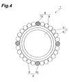
- Fig. 4 is a sectional view of a part of Fig. 3 in a further enlarged manner.
- the FOP 1 includes a plurality of cores 5 that transmit light, a plurality of claddings 6 that cover the outer peripheral portions of the cores 5, and a glass body 8 disposed among the fibers 7.
- the glass body 8 has absorbability for absorbing light (stray light) leaking from the fibers 7 and antimicrobial activities obtained by containing silver oxide.
- the core 5 and the cladding 6 constitute the fiber 7.
- the FOP 1 shown in Fig. 2 to Fig. 4 is adopted mainly in a product whose numerical aperture (NA) of the FOP 1 is not more than 1.
- the cores 5 are fibriform members, and are aligned in a direction crossing the axial direction.
- the cores 5 are made of core glass, and have a function of transmitting light that entered from one end to the other end.
- the plurality of claddings 6 are provided corresponding to the plurality of cores 5, and are made of clad glass with a refractive index lower than that of the core glass.
- the refractive index of the cladding 6 is lower than the refractive index of the core 5, so that light that entered the inside of the core 5 is totally reflected by the interface between the core 5 and the cladding 6. Therefore, the core 5 can propagate light from one end to the other end.
- the glass body 8 is interposed among the plurality of fibers 7.
- the glass body 8 is disposed to cover the outer peripheral portions of the fibers 7.
- the glass body 8 consists of absorbing glass portions (first glass portion) 9 and antimicrobial glass portions (second glass portions) 10.
- the absorbing glass portion 9 has a rod-like shape (single fiber) as shown in Fig. 4 , and a plurality of absorbing glass portions are disposed to surround the outer peripheral portion of the cladding 6.
- the absorbing glass portions 9 are made of absorbing glass having absorbability for absorbing stray light.
- the antimicrobial glass portion 10 has, as shown in Fig. 4 , a rod-like shape (single fiber), and a plurality (four in Fig. 4 ) of antimicrobial glass portions are disposed on the outer peripheral portion of the cladding 6 and among the absorbing glass portions 9.
- the antimicrobial glass portions 10 are made of antimicrobial glass with antimicrobial activities.
- Fig. 5 is a sectional view showing details of the antimicrobial glass portion 10. As shown in Fig. 5 , the outer peripheral portion of the antimicrobial glass portion 10 is covered by a covering glass portion (third glass portion) 11 made of clad glass that does not contain silver oxide.
- the covering glass portion 11 has the same composition as that of the claddings 6 described later.
- the antimicrobial glass portions 10 occupy approximately 6% of the entire end face (refer to Fig. 3 ) of the FOP 1.
- the cores 5 have a diameter of 30 mm
- the claddings 6 have a diameter of 40 mm and a thickness of 4 mm.
- Both of the absorbing glass portions 9 and the antimicrobial glass portions 10 have a diameter of 4 mm.
- Fig. 7 is a diagram showing examples of compositions and characteristics of the cores 5, the claddings 6, the absorbing glass portions 9, and the antimicrobial glass portions 10.
- the contents of compositions are shown in percentages by weight.
- the core glass forming the cores 5 and the clad glass forming the claddings 6 are composed mainly of SiO 2 as a glass network forming oxide (NWF: Network former).
- the core glass and the clad glass do not become glass singly, and are composed by containing a glass network modifying oxide (NWM: Network modifier) that provides glass with appropriate properties by fusion with the NWF, and an intermediate oxide that has properties intermediate between the NWF and the NWM.
- NWM Glass network modifying oxide
- the absorbing glass forming the absorbing glass portions 9 is composed mainly of SiO 2 .
- the absorbing glass contains Fe 3 O 4 .
- This Fe 3 O 4 has a wide absorbing band, and by containing Fe 3 O 4 in the absorbing glass portions 9, absorption characteristics excellent from a visible light region to a near-infrared region can be obtained.
- the absorbing glass portions 9 also contain other materials such as PbO.
- the antimicrobial glass forming the antimicrobial glass portions 10 contains B 2 O 3 , SiO 2 , Al 2 O 3 , Na 2 O, BaO, CaO, and A g2 O as raw materials.
- B 2 O 3 acts as an NWF forming the framework of glass, and also contributes to uniform emission of silver ions (Ag ions).
- B 2 O 3 is contained in a proportion of 20 to 30% of the entirety of the antimicrobial glass portions 10.
- SiO 2 acts as an NWF, and also contributes to prevention of yellowing due to Ag 2 O.
- Al 2 O 3 emits aluminium ions, and contributes to stabilization of silver ions by coupling to silver ions.
- Na 2 O acts as an NWM, and has an activity of improving the transparency of the antimicrobial glass portion 10 and an activity of promoting fusion and elution of glass.
- BaO and CaO have an activity of assisting fusion of glass.
- Ag 2 O is an essential component of the antimicrobial glass portion 10, which is eluted in glass and becomes silver ions having antimicrobial activities, and gives the antimicrobial glass portion 10 the antimicrobial activities.
- the content of Ag 2 O is approximately 0.5 mass%.
- a method for manufacturing the FOP 1 (refer to Fig. 2 ) having the above-described configuration will be referred to as an EMA (Extra Mural Absorption) method.
- a composite body formed of core glass forming the core 5, clad glass forming the cladding 6, and the absorbing glass portion 9 and the antimicrobial glass portion 10 is put into a heating device and stretched with a roller, and accordingly, a single fiber is obtained.
- a multi-fiber is manufactured.
- the multi-fiber is obtained by heating and welding a plurality of single fibers by aligning the plurality of single fibers, and putting the single fibers in a heating device and stretching with a roller.
- a glass body 8 is configured by including the antimicrobial glass portions 10 made of antimicrobial glass containing Ag 2 O.
- the glass containing silver does not have chemical durability, so that it has properties to easily emit Ag ions due to moisture. Ag ions have an excellent antimicrobial effect. Therefore, the glass body 8 is configured by including the antimicrobial glass portions 10 containing Ag 2 O, and accordingly, the glass body 8 can be provided with a sterilization effect due to the action of Ag ions. Therefore, the FOP 1 can be provided with antimicrobial activities.
- the antimicrobial glass portion 10 is covered by a covering glass portion 11 that does not contain silver oxide. Ag ions become metallic Ag due to coexistence with Fe ions in glass. This metallic Ag may deteriorate the sterilization effect of the antimicrobial glass surface. Therefore, by covering the antimicrobial glass portion 10 provided with antimicrobial activities obtained by containing Ag 2 O by the covering glass portion 11 that does not contain Ag 2 O, coexistence with Fe ions of the absorbing glass portion 9 can be avoided, so that the sterilization effect can be prevented from being deteriorated. As a result, the FOP1 can be more reliably provided with antimicrobial activities.
- Fig. 8 shows compositions and properties of antimicrobial glasses used for manufacturing the FOP
- the antimicrobial effect of this FOP was evaluated according to the following steps.
- An antimicrobial test for the FOP was conducted according to a test method conforming to JIS Z 2801 2000. Specifically, the surfaces of a conventional unprocessed specimen not containing Ag 2 O and a specimen of the embodiment were inoculated with test microbes, and the counts of viable microbes after culture for 24 hours were measured.
- a logarithmic value difference antimicrobial activity value
- Staphylococcus aureus and coliform bacillus were used as test strains.
- the number of inoculated microbes of Staphylococcus aureus was 1.8 ⁇ 10 5
- the number of inoculated microbes of coliform bacillus was 2.9 ⁇ 10 5 .
- Fig. 9(a) and Fig. 9(b) show the results of an FOP including the antimicrobial glass of No. 11 of Fig. 8 .
- Fig. 9(a) and Fig. 9(b) it was confirmed that the FOP of the embodiment had the antimicrobial effect.
- Fig. 10 shows relative transmittances of the conventional FOP and the FOP of the embodiment.
- the FOP has a fiber size of 15 ⁇ m and a thickness of 1.75 mm.
- the relative transmittances shown in Fig. 10 are relative transmittances for 850 nm diffusion light.
- the relative transmittance of the FOP of the embodiment is substantially equal to that of the conventional FOP, so that it was confirmed that optical characteristics were substantially the same as those of the conventional product. Concerning the image quality, a substantially similar result was obtained.
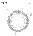
- Fig. 11 is an enlarged sectional view of a part of a fiber optic plate according to a second embodiment of the present invention.
- the FOP 20 is configured in much the same way as the FOP 1 of the first embodiment, and is different from the first embodiment in that the glass body 21 is formed of absorbing glass portions (glass portions) 22.
- the outer peripheral portion of the cladding 6 is covered by a glass body 8 consisting of absorbing glass portions 9 and antimicrobial glass portions 10, however, in the second embodiment, the cladding 6 is covered by a glass body 21 consisting of the absorbing glass portions 22.
- the absorbing glass portions 22 are made of a glass material with absorbability and antimicrobial activities. This glass material is made of the absorbing glass and antimicrobial glass containing Ag 2 O shown in the first embodiment.
- the materials to be used for the core 5 and the cladding 6 are the same as in the first embodiment.
- the FOP 1 is manufactured according to the same production method as that for the FOP 1 of the first embodiment.
- the absorbing glass portions 22 contain Ag 2 O, so that the glass body 21 can obtain a sterilization effect according to the action of Ag ions. Therefore, the FOP 20 can be provided with antimicrobial activities.
- the glass body 8 of the first embodiment is not limited to the above-described configuration.
- the glass body 8 may be formed of an absorber with absorbability and antimicrobial activities and antimicrobial glass portions.
- the glass body 8 may be formed of an absorber and antimicrobial glass portions with absorbability and antimicrobial activities.
- the above-described FOPs 1 and 20 are manufactured according to the EMA method, however, they may be manufactured according to a method called an ISA (Interstitial Absorption) method.
- Fig. 12 shows an FOP manufactured according to the ISA method.
- the cladding 31 is formed integrally and covers the outer peripheral portions of the plurality of cores 5. Further, the cladding 31 covers the outer peripheral portions of the absorbing glass portions 32.
- the absorbing glass portions 32 are made of the same material as in the second embodiment.
- the absorbing glass portions 9, 22, and 32 may not be rod-shaped, but may be tubular.
- the claddings 6 covering the antimicrobial glass portions 10 may not be necessarily provided.
- a fiber optic plate can be provided with antimicrobial activities.
- Fiber optic plate FOP
- 5 Core
- 6 Cladding
- 8 Glass body
- 9 Absorbing glass portion (first glass portion)
- 10 Antimicrobial glass portion (second glass portion)
- 11 Covering glass portion (third glass portion)
- 22, 32 Absorber (glass portion)
Landscapes
- Chemical & Material Sciences (AREA)
- Materials Engineering (AREA)
- Engineering & Computer Science (AREA)
- Chemical Kinetics & Catalysis (AREA)
- General Chemical & Material Sciences (AREA)
- Geochemistry & Mineralogy (AREA)
- Life Sciences & Earth Sciences (AREA)
- Organic Chemistry (AREA)
- Physics & Mathematics (AREA)
- Optics & Photonics (AREA)
- General Physics & Mathematics (AREA)
- Glass Compositions (AREA)
- Optical Fibers, Optical Fiber Cores, And Optical Fiber Bundles (AREA)
Abstract
Description
- The present invention relates to a fiber optic plate and a method for producing the same.
- A fiber optic plate is an optical device configured by bundling optical fibers of several microns, and is used as an optical waveguide of optical equipment such as an image intensifier, a face plate of a CRT, and a CCD coupling, etc.
- As one detailed technique used in the fiber optic plate, there is fingerprint detection (direct image taking) in a fingerprint identification device. In fingerprint detection using a fiber optic plate, it is necessary that a finger of a person to be identified must be made to touch the fiber optic plate, so that in a case where fingerprints of many people to be identified are detected, people who have a resistance to touching the fiber optic plate are not negligible. Therefore, a measure for eliminating such a resistance has been demanded.
- In recent years, from the point of view of sanitation and users' rising concerns about cleanliness, home electric appliances, groceries, and textile products, etc., have been required to have antimicrobial activities, and antimicrobial glass with antimicrobial activities may be contained in resins and fibers forming these products (for example, refer to
Patent Documents 1 to 3). - Patent Document 1: Japanese Published Unexamined Patent Application No.
2000-203876 - Patent Document 2: Japanese Published Unexamined Patent Application No.
Z001-247333 - Patent Document 3: International Publication WHO
05/087675 - Thus, antimicrobial activities of home electric appliances, groceries, and textile products, etc., are realized and realization of antimicrobial activities of a fiber optic plate has also been demanded, and a best mode for this has been demanded.
- Therefore, the present invention has been made in view of these circumstances, and an object thereof is to provide a fiber optic plate with antimicrobial activities.
- In order to achieve the above-described object, a fiber optic plate according to the present invention is configured by bundling a plurality of optical fibers, and includes a plurality of cores that propagates light, claddings for covering the cores, and a glass body which is disposed among the cores and has light absorbability for absorbing stray light that leaked from the cores and entered the claddings and antimicrobial activities obtained by containing silver oxide.
- In this fiber optic plate, the glass body has antimicrobial activities obtained by containing silver oxide. Here, the glass containing silver oxide does not have chemical durability, so that it has properties of easily emitting Ag ions due to moisture. Ag ions have an excellent antimicrobial effect. Due to silver oxide contained in the glass body, the glass body can obtain a sterilization effect according to the action of Ag ions. Therefore, the fiber optic plate can be provided with antimicrobial activities. It is difficult to provide the cores and claddings with antimicrobial activities in terms of transmittance and production. However, by providing the glass body with antimicrobial activities, antimicrobial activities of the fiber optic plate can be realized while eliminating the above-described problem.
- The fiber optic plate according to the present invention preferably includes a glass portion made of a glass material having absorbability and antimicrobial activities. With this configuration, the glass portion has antimicrobial activities, so that the fiber optic plate can be reliably provided with antimicrobial activities.
- In the fiber optic plate according to the present invention, the glass body preferably includes a first glass portion made of a glass material with absorbability and a second glass portion made of a glass material with antimicrobial activities. With this configuration, the second glass portion has antimicrobial activities, so that the fiber optic plate can be reliably provided with antimicrobial activities.
- In the fiber optic plate according to the present invention, the second glass portion is preferably covered by a third glass portion that does not contain silver oxide. Ag ions become metallic Ag when they coexist with Fe ions in glass. This metallic Ag may deteriorate the sterilization effect of the antimicrobial glass surface. Therefore, by covering the second glass portion that has antimicrobial activities due to containing silver oxide by a third glass portion that does not contain silver oxide, coexistence with Fe ions of the first glass portion can be avoided, so that the antimicrobial effect can be prevented from being deteriorated. As a result, the fiber optic plate can be more reliably provided with antimicrobial activities.
- A method for producing a fiber optic plate according to the present invention is for producing a fiber optic plate configured by bundling a plurality of optical fibers, and by the method, a plurality of cores that propagate light, claddings that cover the cores, and a glass body which is disposed among the cores and has light absorbability for absorbing stray light that leaked from the cores and entered the claddings and antimicrobial activities obtained by containing silver oxide, are integrated.
- According to this method for producing a fiber optic plate, the above-described fiber optic plate according to the present invention can be preferably produced.
- According to the present invention, a fiber optic plate can be provided with antimicrobial activities.
-
Fig. 1 is a perspective view of a fiber optic plate according to a first embodiment of the present invention. -
Fig 2 is a perspective view of an internal structure of the fiber optic plate in an enlarged manner. -
Fig. 3 is a sectional view of a part ofFig. 2 in an enlarged manner. -
Fig. 4 is a sectional view showing a part ofFig. 3 in a further enlarged manner. -
Fig. 5 is a sectional view showing details of an antimicrobial glass portion. -
Fig. 6 is a diagram showing sizes of constituent materials of the fiber optic plate. -
Fig. 7 is a diagram showing examples of compositions and characteristics of constituent materials of the fiber optic plate. -
Fig. 8 is a diagram showing compositions and characteristics of antimicrobial glasses used for manufacturing the fiber optic plate. -
Figs. 9 are diagrams showing antimicrobial effect judgment results of the fiber optic plate. -
Fig. 10 is a diagram showing relative transmittances of a conventional fiber optic plate and a fiber optic plate of the embodiment. -
Fig. 11 is an enlarged sectional view of a part of a fiber optic plate according to a second embodiment of the present invention. -
Fig. 12 is a view showing an internal structure of a fiber optic plate manufactured according to an ISA method in an enlarged manner. - Hereinafter, preferred embodiments of the present invention will be described in detail with reference to the drawings. In the drawings, portions identical or equivalent to each other are provided with the same reference numeral, and overlapping description will be omitted.
-
Fig. 1 is a perspective view of a fiber optic plate according to a first embodiment of the present invention. The fiber optic plate (hereinafter, referred to as FOP) 1 shown inFig. 1 is a columnar optical device configured by bundling a plurality ofoptical fibers 7, and has anincidence plane 2 and anexit plane 3. TheFOP 1 has a function of transmitting light andimage 4 that entered from theincidence plane 2 to theexit plane 3, and is used as an optical waveguide of optical equipment, for example, an image intensifier, a face plate of a CRT, a CCD coupling, and a fingerprint detection device, etc. -
Fig. 2 is a perspective view showing an internal structure of the FOP in an enlarged manner.Fig. 3 is a sectional view of a part ofFig. 2 in an enlarged manner, andFig. 4 is a sectional view of a part ofFig. 3 in a further enlarged manner. As shown inFig. 2 to Fig. 4 , theFOP 1 includes a plurality ofcores 5 that transmit light, a plurality ofcladdings 6 that cover the outer peripheral portions of thecores 5, and aglass body 8 disposed among thefibers 7. Theglass body 8 has absorbability for absorbing light (stray light) leaking from thefibers 7 and antimicrobial activities obtained by containing silver oxide. Thecore 5 and thecladding 6 constitute thefiber 7. TheFOP 1 shown inFig. 2 to Fig. 4 is adopted mainly in a product whose numerical aperture (NA) of theFOP 1 is not more than 1. - The
cores 5 are fibriform members, and are aligned in a direction crossing the axial direction. Thecores 5 are made of core glass, and have a function of transmitting light that entered from one end to the other end. - The plurality of
claddings 6 are provided corresponding to the plurality ofcores 5, and are made of clad glass with a refractive index lower than that of the core glass. The refractive index of thecladding 6 is lower than the refractive index of thecore 5, so that light that entered the inside of thecore 5 is totally reflected by the interface between thecore 5 and thecladding 6. Therefore, thecore 5 can propagate light from one end to the other end. - The
glass body 8 is interposed among the plurality offibers 7. Theglass body 8 is disposed to cover the outer peripheral portions of thefibers 7. Theglass body 8 consists of absorbing glass portions (first glass portion) 9 and antimicrobial glass portions (second glass portions) 10. - The absorbing
glass portion 9 has a rod-like shape (single fiber) as shown inFig. 4 , and a plurality of absorbing glass portions are disposed to surround the outer peripheral portion of thecladding 6. The absorbingglass portions 9 are made of absorbing glass having absorbability for absorbing stray light. - The
antimicrobial glass portion 10 has, as shown inFig. 4 , a rod-like shape (single fiber), and a plurality (four inFig. 4 ) of antimicrobial glass portions are disposed on the outer peripheral portion of thecladding 6 and among the absorbingglass portions 9. Theantimicrobial glass portions 10 are made of antimicrobial glass with antimicrobial activities.Fig. 5 is a sectional view showing details of theantimicrobial glass portion 10. As shown inFig. 5 , the outer peripheral portion of theantimicrobial glass portion 10 is covered by a covering glass portion (third glass portion) 11 made of clad glass that does not contain silver oxide. The coveringglass portion 11 has the same composition as that of thecladdings 6 described later. Theantimicrobial glass portions 10 occupy approximately 6% of the entire end face (refer toFig. 3 ) of theFOP 1. - Next, the sizes of the above-described
cores 5, thecladdings 6, the absorbingglass portions 9, and theantimicrobial glass portions 10 will be described with reference toFig. 6 . As shown inFig. 6 , thecores 5 have a diameter of 30 mm, and thecladdings 6 have a diameter of 40 mm and a thickness of 4 mm. Both of the absorbingglass portions 9 and theantimicrobial glass portions 10 have a diameter of 4 mm. - Subsequently, constituent materials of the
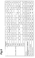
FOP 1 will be described in detail with reference toFig. 7. Fig. 7 is a diagram showing examples of compositions and characteristics of thecores 5, thecladdings 6, the absorbingglass portions 9, and theantimicrobial glass portions 10. InFig. 7 , the contents of compositions are shown in percentages by weight. As shown inFig. 7 , the core glass forming thecores 5 and the clad glass forming thecladdings 6 are composed mainly of SiO2 as a glass network forming oxide (NWF: Network former). The core glass and the clad glass do not become glass singly, and are composed by containing a glass network modifying oxide (NWM: Network modifier) that provides glass with appropriate properties by fusion with the NWF, and an intermediate oxide that has properties intermediate between the NWF and the NWM. - The absorbing glass forming the absorbing
glass portions 9 is composed mainly of SiO2. The absorbing glass contains Fe3O4. This Fe3O4 has a wide absorbing band, and by containing Fe3O4 in the absorbingglass portions 9, absorption characteristics excellent from a visible light region to a near-infrared region can be obtained. The absorbingglass portions 9 also contain other materials such as PbO. - The antimicrobial glass forming the
antimicrobial glass portions 10 contains B2O3, SiO2, Al2O3, Na2O, BaO, CaO, and Ag2O as raw materials. B2O3 acts as an NWF forming the framework of glass, and also contributes to uniform emission of silver ions (Ag ions). B2O3 is contained in a proportion of 20 to 30% of the entirety of theantimicrobial glass portions 10. SiO2 acts as an NWF, and also contributes to prevention of yellowing due to Ag2O. Al2O3 emits aluminium ions, and contributes to stabilization of silver ions by coupling to silver ions. Na2O acts as an NWM, and has an activity of improving the transparency of theantimicrobial glass portion 10 and an activity of promoting fusion and elution of glass. BaO and CaO have an activity of assisting fusion of glass. - Ag2O (silver oxide) is an essential component of the
antimicrobial glass portion 10, which is eluted in glass and becomes silver ions having antimicrobial activities, and gives theantimicrobial glass portion 10 the antimicrobial activities. The content of Ag2O is approximately 0.5 mass%. - Next, an example of a method for producing an
FOP 1 using the above-described constituent materials will be described. A method for manufacturing the FOP 1 (refer toFig. 2 ) having the above-described configuration will be referred to as an EMA (Extra Mural Absorption) method. - First, a composite body formed of core glass forming the
core 5, clad glass forming thecladding 6, and the absorbingglass portion 9 and theantimicrobial glass portion 10 is put into a heating device and stretched with a roller, and accordingly, a single fiber is obtained. - Next, by using the manufactured single fiber, a multi-fiber is manufactured. The multi-fiber is obtained by heating and welding a plurality of single fibers by aligning the plurality of single fibers, and putting the single fibers in a heating device and stretching with a roller.
- Subsequently, by aligning multi-fibers in an octagonal mold of a hot pressing machine and pressing them at a high temperature, the plurality of multi-fibers are heated and welded, and accordingly, an octagonal ingot is obtained. Then, the ingot is sliced perpendicularly to the axial direction and polished, and accordingly, an
FOP 1 is obtained. - As described above, in the
FOP 1 according to the present embodiment, aglass body 8 is configured by including theantimicrobial glass portions 10 made of antimicrobial glass containing Ag2O. Here, the glass containing silver does not have chemical durability, so that it has properties to easily emit Ag ions due to moisture. Ag ions have an excellent antimicrobial effect. Therefore, theglass body 8 is configured by including theantimicrobial glass portions 10 containing Ag2O, and accordingly, theglass body 8 can be provided with a sterilization effect due to the action of Ag ions. Therefore, theFOP 1 can be provided with antimicrobial activities. - It is difficult to make the
cores 5 and thecladdings 6 of antimicrobial glass in terms of transmittance and production. However, by making theantimicrobial glass portions 10 constituting theglass body 8 of antimicrobial glass, antimicrobial activities of theFOP 1 can be realized while the above-described problem is solved. - The
antimicrobial glass portion 10 is covered by a coveringglass portion 11 that does not contain silver oxide. Ag ions become metallic Ag due to coexistence with Fe ions in glass. This metallic Ag may deteriorate the sterilization effect of the antimicrobial glass surface. Therefore, by covering theantimicrobial glass portion 10 provided with antimicrobial activities obtained by containing Ag2O by the coveringglass portion 11 that does not contain Ag2O, coexistence with Fe ions of the absorbingglass portion 9 can be avoided, so that the sterilization effect can be prevented from being deteriorated. As a result, the FOP1 can be more reliably provided with antimicrobial activities. - Hereinafter, the present invention will be described in greater detail based on embodiments and conventional examples, however, the following embodiments are not intended to limit the present invention at all.
- The inventors of the present invention manufactured a FOP having the above-described configuration.
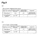
Fig. 8 shows compositions and properties of antimicrobial glasses used for manufacturing the FOP The antimicrobial effect of this FOP was evaluated according to the following steps. An antimicrobial test for the FOP was conducted according to a test method conforming to JIS Z 2801 2000. Specifically, the surfaces of a conventional unprocessed specimen not containing Ag2O and a specimen of the embodiment were inoculated with test microbes, and the counts of viable microbes after culture for 24 hours were measured. JIS regulates that in the case where a logarithmic value difference (antimicrobial activity value) between the count of viable microbes of the conventional unprocessed specimen and the count of viable microbes of the specimen of the embodiment is not less than 2.0, the antimicrobial effect is effective. As test strains, Staphylococcus aureus and coliform bacillus were used. The number of inoculated microbes of Staphylococcus aureus was 1.8×10⁵, and the number of inoculated microbes of coliform bacillus was 2.9×10⁵. - The results obtained through the above-described test are shown in
Fig. 9(a) and Fig. 9(b) . The results shown inFig. 9(a) and Fig. 9(b) show the results of an FOP including the antimicrobial glass of No. 11 ofFig. 8 . As shown inFig. 9(a) and Fig. 9(b) , it was confirmed that the FOP of the embodiment had the antimicrobial effect. -
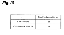
Fig. 10 shows relative transmittances of the conventional FOP and the FOP of the embodiment. In both of the conventional example and the embodiment, the FOP has a fiber size of 15 µm and a thickness of 1.75 mm. The relative transmittances shown inFig. 10 are relative transmittances for 850 nm diffusion light. As shown inFig. 10 , the relative transmittance of the FOP of the embodiment is substantially equal to that of the conventional FOP, so that it was confirmed that optical characteristics were substantially the same as those of the conventional product. Concerning the image quality, a substantially similar result was obtained. -
Fig. 11 is an enlarged sectional view of a part of a fiber optic plate according to a second embodiment of the present invention. As shown inFig. 11 , theFOP 20 is configured in much the same way as theFOP 1 of the first embodiment, and is different from the first embodiment in that theglass body 21 is formed of absorbing glass portions (glass portions) 22. - Specifically, in the first embodiment, the outer peripheral portion of the
cladding 6 is covered by aglass body 8 consisting of absorbingglass portions 9 andantimicrobial glass portions 10, however, in the second embodiment, thecladding 6 is covered by aglass body 21 consisting of the absorbingglass portions 22. The absorbingglass portions 22 are made of a glass material with absorbability and antimicrobial activities. This glass material is made of the absorbing glass and antimicrobial glass containing Ag2O shown in the first embodiment. The materials to be used for thecore 5 and thecladding 6 are the same as in the first embodiment. TheFOP 1 is manufactured according to the same production method as that for theFOP 1 of the first embodiment. - As described above, in the
FOP 20 according to the second embodiment, as in the first embodiment, the absorbingglass portions 22 contain Ag2O, so that theglass body 21 can obtain a sterilization effect according to the action of Ag ions. Therefore, theFOP 20 can be provided with antimicrobial activities. - The present invention is not limited to the above-described embodiments.
- For example, the
glass body 8 of the first embodiment is not limited to the above-described configuration. Theglass body 8 may be formed of an absorber with absorbability and antimicrobial activities and antimicrobial glass portions. Theglass body 8 may be formed of an absorber and antimicrobial glass portions with absorbability and antimicrobial activities. - The above-described
FOPs Fig. 12 shows an FOP manufactured according to the ISA method. As shown in this figure, in theFOP 30 manufactured according to the ISA method, thecladding 31 is formed integrally and covers the outer peripheral portions of the plurality ofcores 5. Further, thecladding 31 covers the outer peripheral portions of the absorbingglass portions 32. The absorbingglass portions 32 are made of the same material as in the second embodiment. - The absorbing
glass portions claddings 6 covering theantimicrobial glass portions 10 may not be necessarily provided. - According to the present invention, a fiber optic plate can be provided with antimicrobial activities.
- 1, 20, 30: Fiber optic plate (FOP), 5: Core, 6, 31: Cladding, 8, 21: Glass body, 9: Absorbing glass portion (first glass portion), 10: Antimicrobial glass portion (second glass portion), 11: Covering glass portion (third glass portion), 22, 32: Absorber (glass portion)
Claims (5)
- A fiber optic plate configured by bundling a plurality of optical fibers, comprising:a plurality of cores that propagate light;claddings for covering the cores; anda glass body which is disposed among the cores and has light absorbability for absorbing stray light that leaked from the cores and entered the claddings and antimicrobial activities obtained by containing silver oxide.
- The fiber optic plate according to Claim 1, wherein the glass body includes a glass portion made of a glass material having the absorbability and the antimicrobial activities.
- The fiber optic plate according to Claim 1, wherein the glass body includes a first glass portion made of a glass material with the absorbability and a second glass portion made of a glass material with the antimicrobial activities.
- The fiber optic plate according to Claim 3, wherein the second glass portion is covered by a third glass portion that does not contain silver oxide.
- A method for producing a fiber optic plate configured by bundling a plurality of optical fibers, wherein
a plurality of cores that propagate light;
claddings for covering the cores; and
a glass body which is disposed among the cores and has light absorbability for absorbing stray light that leaked from the cores and entered the claddings and antimicrobial activities obtained by containing silver oxide, are integrated.
Applications Claiming Priority (2)
| Application Number | Priority Date | Filing Date | Title |
|---|---|---|---|
| JP2008295615A JP5171569B2 (en) | 2008-11-19 | 2008-11-19 | Fiber optic plate and manufacturing method thereof |
| PCT/JP2009/066653 WO2010058653A1 (en) | 2008-11-19 | 2009-09-25 | Fiber optic plate and method for producing the same |
Publications (3)
| Publication Number | Publication Date |
|---|---|
| EP2354821A1 true EP2354821A1 (en) | 2011-08-10 |
| EP2354821A4 EP2354821A4 (en) | 2012-05-09 |
| EP2354821B1 EP2354821B1 (en) | 2015-11-11 |
Family
ID=42198092
Family Applications (1)
| Application Number | Title | Priority Date | Filing Date |
|---|---|---|---|
| EP09827434.3A Not-in-force EP2354821B1 (en) | 2008-11-19 | 2009-09-25 | Fiber optic plate and method for producing the same |
Country Status (6)
| Country | Link |
|---|---|
| US (3) | US20110222827A1 (en) |
| EP (1) | EP2354821B1 (en) |
| JP (1) | JP5171569B2 (en) |
| KR (1) | KR101709356B1 (en) |
| TW (1) | TWI503584B (en) |
| WO (1) | WO2010058653A1 (en) |
Cited By (1)
| Publication number | Priority date | Publication date | Assignee | Title |
|---|---|---|---|---|
| US10131574B2 (en) | 2013-06-17 | 2018-11-20 | Corning Incorporated | Antimicrobial glass articles and methods of making and using same |
Families Citing this family (6)
| Publication number | Priority date | Publication date | Assignee | Title |
|---|---|---|---|---|
| DE102012207405B3 (en) * | 2012-05-04 | 2013-08-14 | Schott Ag | Glass-ceramic additive for aggregate material, contains specified amount of silica, boric oxide, alumina, calcium oxide, barium oxide, magnesium oxide, zirconium oxide and yttrium oxide, and has preset thermal expansion coefficient |
| FR2993203B1 (en) * | 2012-07-11 | 2014-07-18 | Saint Gobain | BRIGHT GLAZING |
| CN109839695B (en) * | 2017-11-28 | 2020-08-14 | 上海箩箕技术有限公司 | Optical fiber panel and debugging method thereof |
| JP7136534B2 (en) | 2019-05-07 | 2022-09-13 | 株式会社豊田中央研究所 | Optical fiber laser device |
| CN111253068B (en) * | 2020-01-29 | 2022-02-18 | 北方夜视技术股份有限公司 | High-resolution high-modulation-degree absorbing glass for inverted camera and preparation method thereof |
| EP3904306B1 (en) | 2020-04-30 | 2023-06-07 | Schott Ag | Multi-fiber light guide, device with a multi-fiber light guide and method for producing the same |
Family Cites Families (43)
| Publication number | Priority date | Publication date | Assignee | Title |
|---|---|---|---|---|
| US3253500A (en) * | 1964-05-11 | 1966-05-31 | American Optical Corp | Doubly clad light-conducting fibers with the outer cladding being partially light absorbing |
| US4415810A (en) * | 1979-07-05 | 1983-11-15 | Brown Sr Robert L | Device for imaging penetrating radiation |
| JPH0450878A (en) | 1990-06-14 | 1992-02-19 | Ricoh Co Ltd | developer carrier |
| JP2890735B2 (en) | 1990-08-03 | 1999-05-17 | スズキ株式会社 | Casting mold |
| JPH04177304A (en) * | 1990-11-13 | 1992-06-24 | Fukuoka Cloth Kogyo Kk | Water-permeation-proof optical cable |
| JP3218096B2 (en) | 1992-09-18 | 2001-10-15 | 泉陽硝子工業株式会社 | Antibacterial glass |
| US5319731A (en) * | 1992-10-02 | 1994-06-07 | Eastman Kodak Company | Fiber-optic array of limited acceptance angle |
| JPH06289262A (en) * | 1993-03-31 | 1994-10-18 | Showa Electric Wire & Cable Co Ltd | Fiber optic cable |
| JPH0788236A (en) | 1993-09-21 | 1995-04-04 | Ace Denken:Kk | Ball throwing device in the upper plate of the pachinko machine |
| JP3486951B2 (en) | 1994-05-09 | 2004-01-13 | 日本板硝子株式会社 | Antibacterial glass composition |
| JPH0848539A (en) | 1994-06-02 | 1996-02-20 | Nippon Sheet Glass Co Ltd | Antibacterial glass composition |
| JPH0891847A (en) | 1994-09-28 | 1996-04-09 | Nippon Sheet Glass Co Ltd | Glass meliting furnace |
| JPH08184717A (en) * | 1994-11-01 | 1996-07-16 | Nikon Corp | Finder device |
| JPH08245237A (en) | 1995-03-09 | 1996-09-24 | Nippon Sheet Glass Co Ltd | Composition for antibacterial glass |
| JPH08338916A (en) * | 1995-06-12 | 1996-12-24 | Hamamatsu Photonics Kk | Fiber optic plate |
| JPH10158037A (en) | 1996-11-27 | 1998-06-16 | Asahi Glass Co Ltd | Antibacterial glass and method for producing the same |
| JPH10160948A (en) * | 1996-12-04 | 1998-06-19 | Hamamatsu Photonics Kk | Fiber optic plate |
| JPH11228186A (en) | 1998-02-09 | 1999-08-24 | Nippon Parkerizing Co Ltd | Glass, method for producing glass, and composition for tempered antibacterial glass |
| JP3349450B2 (en) | 1998-08-24 | 2002-11-25 | 関西ペイント株式会社 | Method of forming resist pattern |
| JP2000169185A (en) | 1998-12-11 | 2000-06-20 | Nippon Electric Glass Co Ltd | Antibacterial crystallized glass article and its production |
| JP2000191339A (en) | 1998-12-28 | 2000-07-11 | Koa Glass Kk | Dissoluble glass, antibacterial resin composition and antibacterial molded article |
| JP2000203876A (en) | 1998-12-28 | 2000-07-25 | Nippon Sheet Glass Co Ltd | Antimicrobial glass and resin composition containing the glass |
| JP2000327364A (en) | 1999-05-21 | 2000-11-28 | Ishizuka Glass Co Ltd | Antibacterial glass composition |
| JP2001097735A (en) | 1999-10-01 | 2001-04-10 | Nippon Electric Glass Co Ltd | Antibacterial glass and method for producing the same |
| JP2001247333A (en) | 1999-12-28 | 2001-09-11 | Ishizuka Glass Co Ltd | Antibacterial glass composition, antibacterial fiber, antibacterial twisted yarn and antibacterial cloth |
| JP2000313624A (en) | 2000-01-01 | 2000-11-14 | Ion Kogaku Shinko Zaidan | Manufacturing method of antibacterial glass |
| JP2001226139A (en) | 2000-02-15 | 2001-08-21 | Nippon Sheet Glass Co Ltd | Antibacterial glass and resin composition containing the same |
| JP2001240426A (en) | 2000-02-25 | 2001-09-04 | Nippon Sheet Glass Co Ltd | Antibacterial glass and resin composition containing the same |
| JP2002037643A (en) | 2000-07-24 | 2002-02-06 | Nippon Electric Glass Co Ltd | Antimicrobial glass and its resin components |
| JP3744779B2 (en) | 2000-08-29 | 2006-02-15 | 松下電器産業株式会社 | Pulse generator |
| JP2003242488A (en) | 2002-02-18 | 2003-08-29 | Casio Comput Co Ltd | Imaging device |
| JP4005393B2 (en) | 2002-03-13 | 2007-11-07 | 東亞合成株式会社 | Method for producing silver-based glassy antibacterial agent with excellent antibacterial effect |
| JP2005107308A (en) * | 2003-09-30 | 2005-04-21 | Nissei Electric Co Ltd | Light guide |
| US7221835B1 (en) | 2003-11-25 | 2007-05-22 | Schott Corporation | Ion-reduction-blackened extra-mural absorbing media adapted for inclusion in image-conducting optical fiber arrays and methods of fabricating the same |
| KR100657123B1 (en) * | 2004-03-15 | 2006-12-13 | 코아 가라스 가부시키가이샤 | Antibacterial glass and method for producing antibacterial glass |
| WO2006120772A1 (en) * | 2005-05-10 | 2006-11-16 | Koa Glass Co., Ltd | Antimicrobial fiber and method for production thereof |
| KR200396126Y1 (en) * | 2005-07-06 | 2005-09-15 | 전원희 | Antibacterial Deodorization device for Darkroom |
| WO2007018287A1 (en) * | 2005-08-11 | 2007-02-15 | Kyowa Hakko Chemical Co., Ltd. | Resin composition |
| US7960465B2 (en) * | 2006-06-30 | 2011-06-14 | Johnson & Johnson Vision Care, Inc. | Antimicrobial lenses, processes to prepare them and methods of their use |
| US20080085326A1 (en) * | 2006-10-04 | 2008-04-10 | Hai Xiong Ruan | Antimicrobial material compositions enriched with different active oxygen species |
| JP5259096B2 (en) * | 2007-02-13 | 2013-08-07 | 浜松ホトニクス株式会社 | Fiber optic and manufacturing method thereof |
| US20080286713A1 (en) * | 2007-05-16 | 2008-11-20 | Puneet Nanda | Toothbrush with illumination system |
| US20150090475A1 (en) * | 2013-03-15 | 2015-04-02 | General Cable Technologies Corporation | Cables having an antimicrobial coating |
-
2008
- 2008-11-19 JP JP2008295615A patent/JP5171569B2/en not_active Expired - Fee Related
-
2009
- 2009-09-25 EP EP09827434.3A patent/EP2354821B1/en not_active Not-in-force
- 2009-09-25 KR KR1020117005655A patent/KR101709356B1/en not_active Expired - Fee Related
- 2009-09-25 WO PCT/JP2009/066653 patent/WO2010058653A1/en not_active Ceased
- 2009-09-25 US US13/130,013 patent/US20110222827A1/en not_active Abandoned
- 2009-10-08 TW TW098134134A patent/TWI503584B/en not_active IP Right Cessation
-
2017
- 2017-07-03 US US15/640,791 patent/US10209441B2/en active Active
-
2019
- 2019-01-02 US US16/238,004 patent/US10802211B2/en active Active
Cited By (1)
| Publication number | Priority date | Publication date | Assignee | Title |
|---|---|---|---|---|
| US10131574B2 (en) | 2013-06-17 | 2018-11-20 | Corning Incorporated | Antimicrobial glass articles and methods of making and using same |
Also Published As
| Publication number | Publication date |
|---|---|
| US20190154915A1 (en) | 2019-05-23 |
| EP2354821B1 (en) | 2015-11-11 |
| JP5171569B2 (en) | 2013-03-27 |
| US20170307816A1 (en) | 2017-10-26 |
| JP2010122436A (en) | 2010-06-03 |
| EP2354821A4 (en) | 2012-05-09 |
| KR101709356B1 (en) | 2017-02-22 |
| TWI503584B (en) | 2015-10-11 |
| WO2010058653A1 (en) | 2010-05-27 |
| US10802211B2 (en) | 2020-10-13 |
| US20110222827A1 (en) | 2011-09-15 |
| US10209441B2 (en) | 2019-02-19 |
| TW201030400A (en) | 2010-08-16 |
| KR20110086546A (en) | 2011-07-28 |
Similar Documents
| Publication | Publication Date | Title |
|---|---|---|
| US10802211B2 (en) | Fiber optic plate and method for producing the same | |
| EP2110693B1 (en) | Fiber optic | |
| US11926564B2 (en) | Transition metal-containing, ion exchangeable colored glasses | |
| JP2014141363A (en) | Chemically strengthenable glass, glass sheet, and chemically strengthened cover glass | |
| CN106772791A (en) | Low stray light crosstalk type fibre optic image transmission element and preparation method thereof | |
| TW593195B (en) | Multicomponent glass, glass fiber, twister and taper | |
| EP0752394B1 (en) | Glass and fiber optic plate using the same | |
| US12292594B2 (en) | Multi-fiber light guide, device with a multi-fiber light guide and method for producing the same | |
| EP4582842B1 (en) | Optical fiber image inverter with ultra-narrow twisted fiber area and preparation method therefor and application thereof, and related composition | |
| JPS58149007A (en) | Multiple fibers | |
| JP4046786B2 (en) | Fiber optic plate | |
| JPH0971436A5 (en) | ||
| JP2509330B2 (en) | Image fiber and manufacturing method thereof | |
| JP4060568B2 (en) | Absorber glass and fiber optic plate |
Legal Events
| Date | Code | Title | Description |
|---|---|---|---|
| PUAI | Public reference made under article 153(3) epc to a published international application that has entered the european phase |
Free format text: ORIGINAL CODE: 0009012 |
|
| 17P | Request for examination filed |
Effective date: 20110607 |
|
| AK | Designated contracting states |
Kind code of ref document: A1 Designated state(s): AT BE BG CH CY CZ DE DK EE ES FI FR GB GR HR HU IE IS IT LI LT LU LV MC MK MT NL NO PL PT RO SE SI SK SM TR |
|
| DAX | Request for extension of the european patent (deleted) | ||
| A4 | Supplementary search report drawn up and despatched |
Effective date: 20120412 |
|
| RIC1 | Information provided on ipc code assigned before grant |
Ipc: C03C 13/04 20060101ALI20120405BHEP Ipc: C03C 3/064 20060101ALI20120405BHEP Ipc: G02B 6/06 20060101AFI20120405BHEP Ipc: C03C 3/102 20060101ALI20120405BHEP Ipc: C03C 4/00 20060101ALI20120405BHEP Ipc: C03C 4/08 20060101ALI20120405BHEP Ipc: C03C 3/093 20060101ALI20120405BHEP Ipc: G02B 6/08 20060101ALI20120405BHEP |
|
| GRAP | Despatch of communication of intention to grant a patent |
Free format text: ORIGINAL CODE: EPIDOSNIGR1 |
|
| INTG | Intention to grant announced |
Effective date: 20150520 |
|
| GRAS | Grant fee paid |
Free format text: ORIGINAL CODE: EPIDOSNIGR3 |
|
| GRAA | (expected) grant |
Free format text: ORIGINAL CODE: 0009210 |
|
| AK | Designated contracting states |
Kind code of ref document: B1 Designated state(s): AT BE BG CH CY CZ DE DK EE ES FI FR GB GR HR HU IE IS IT LI LT LU LV MC MK MT NL NO PL PT RO SE SI SK SM TR |
|
| REG | Reference to a national code |
Ref country code: GB Ref legal event code: FG4D |
|
| REG | Reference to a national code |
Ref country code: CH Ref legal event code: EP |
|
| REG | Reference to a national code |
Ref country code: IE Ref legal event code: FG4D |
|
| REG | Reference to a national code |
Ref country code: AT Ref legal event code: REF Ref document number: 760736 Country of ref document: AT Kind code of ref document: T Effective date: 20151215 |
|
| REG | Reference to a national code |
Ref country code: DE Ref legal event code: R096 Ref document number: 602009034875 Country of ref document: DE |
|
| REG | Reference to a national code |
Ref country code: LT Ref legal event code: MG4D |
|
| REG | Reference to a national code |
Ref country code: NL Ref legal event code: MP Effective date: 20160211 |
|
| REG | Reference to a national code |
Ref country code: AT Ref legal event code: MK05 Ref document number: 760736 Country of ref document: AT Kind code of ref document: T Effective date: 20151111 |
|
| PG25 | Lapsed in a contracting state [announced via postgrant information from national office to epo] |
Ref country code: IT Free format text: LAPSE BECAUSE OF FAILURE TO SUBMIT A TRANSLATION OF THE DESCRIPTION OR TO PAY THE FEE WITHIN THE PRESCRIBED TIME-LIMIT Effective date: 20151111 Ref country code: IS Free format text: LAPSE BECAUSE OF FAILURE TO SUBMIT A TRANSLATION OF THE DESCRIPTION OR TO PAY THE FEE WITHIN THE PRESCRIBED TIME-LIMIT Effective date: 20160311 Ref country code: NL Free format text: LAPSE BECAUSE OF FAILURE TO SUBMIT A TRANSLATION OF THE DESCRIPTION OR TO PAY THE FEE WITHIN THE PRESCRIBED TIME-LIMIT Effective date: 20151111 Ref country code: LT Free format text: LAPSE BECAUSE OF FAILURE TO SUBMIT A TRANSLATION OF THE DESCRIPTION OR TO PAY THE FEE WITHIN THE PRESCRIBED TIME-LIMIT Effective date: 20151111 Ref country code: NO Free format text: LAPSE BECAUSE OF FAILURE TO SUBMIT A TRANSLATION OF THE DESCRIPTION OR TO PAY THE FEE WITHIN THE PRESCRIBED TIME-LIMIT Effective date: 20160211 Ref country code: HR Free format text: LAPSE BECAUSE OF FAILURE TO SUBMIT A TRANSLATION OF THE DESCRIPTION OR TO PAY THE FEE WITHIN THE PRESCRIBED TIME-LIMIT Effective date: 20151111 Ref country code: ES Free format text: LAPSE BECAUSE OF FAILURE TO SUBMIT A TRANSLATION OF THE DESCRIPTION OR TO PAY THE FEE WITHIN THE PRESCRIBED TIME-LIMIT Effective date: 20151111 |
|
| PG25 | Lapsed in a contracting state [announced via postgrant information from national office to epo] |
Ref country code: AT Free format text: LAPSE BECAUSE OF FAILURE TO SUBMIT A TRANSLATION OF THE DESCRIPTION OR TO PAY THE FEE WITHIN THE PRESCRIBED TIME-LIMIT Effective date: 20151111 Ref country code: PT Free format text: LAPSE BECAUSE OF FAILURE TO SUBMIT A TRANSLATION OF THE DESCRIPTION OR TO PAY THE FEE WITHIN THE PRESCRIBED TIME-LIMIT Effective date: 20160311 Ref country code: FI Free format text: LAPSE BECAUSE OF FAILURE TO SUBMIT A TRANSLATION OF THE DESCRIPTION OR TO PAY THE FEE WITHIN THE PRESCRIBED TIME-LIMIT Effective date: 20151111 Ref country code: PL Free format text: LAPSE BECAUSE OF FAILURE TO SUBMIT A TRANSLATION OF THE DESCRIPTION OR TO PAY THE FEE WITHIN THE PRESCRIBED TIME-LIMIT Effective date: 20151111 Ref country code: SE Free format text: LAPSE BECAUSE OF FAILURE TO SUBMIT A TRANSLATION OF THE DESCRIPTION OR TO PAY THE FEE WITHIN THE PRESCRIBED TIME-LIMIT Effective date: 20151111 Ref country code: LV Free format text: LAPSE BECAUSE OF FAILURE TO SUBMIT A TRANSLATION OF THE DESCRIPTION OR TO PAY THE FEE WITHIN THE PRESCRIBED TIME-LIMIT Effective date: 20151111 Ref country code: GR Free format text: LAPSE BECAUSE OF FAILURE TO SUBMIT A TRANSLATION OF THE DESCRIPTION OR TO PAY THE FEE WITHIN THE PRESCRIBED TIME-LIMIT Effective date: 20160212 |
|
| PG25 | Lapsed in a contracting state [announced via postgrant information from national office to epo] |
Ref country code: CZ Free format text: LAPSE BECAUSE OF FAILURE TO SUBMIT A TRANSLATION OF THE DESCRIPTION OR TO PAY THE FEE WITHIN THE PRESCRIBED TIME-LIMIT Effective date: 20151111 |
|
| REG | Reference to a national code |
Ref country code: DE Ref legal event code: R097 Ref document number: 602009034875 Country of ref document: DE |
|
| REG | Reference to a national code |
Ref country code: FR Ref legal event code: PLFP Year of fee payment: 8 |
|
| PG25 | Lapsed in a contracting state [announced via postgrant information from national office to epo] |
Ref country code: SK Free format text: LAPSE BECAUSE OF FAILURE TO SUBMIT A TRANSLATION OF THE DESCRIPTION OR TO PAY THE FEE WITHIN THE PRESCRIBED TIME-LIMIT Effective date: 20151111 Ref country code: SM Free format text: LAPSE BECAUSE OF FAILURE TO SUBMIT A TRANSLATION OF THE DESCRIPTION OR TO PAY THE FEE WITHIN THE PRESCRIBED TIME-LIMIT Effective date: 20151111 Ref country code: EE Free format text: LAPSE BECAUSE OF FAILURE TO SUBMIT A TRANSLATION OF THE DESCRIPTION OR TO PAY THE FEE WITHIN THE PRESCRIBED TIME-LIMIT Effective date: 20151111 Ref country code: RO Free format text: LAPSE BECAUSE OF FAILURE TO SUBMIT A TRANSLATION OF THE DESCRIPTION OR TO PAY THE FEE WITHIN THE PRESCRIBED TIME-LIMIT Effective date: 20151111 Ref country code: DK Free format text: LAPSE BECAUSE OF FAILURE TO SUBMIT A TRANSLATION OF THE DESCRIPTION OR TO PAY THE FEE WITHIN THE PRESCRIBED TIME-LIMIT Effective date: 20151111 |
|
| PLBE | No opposition filed within time limit |
Free format text: ORIGINAL CODE: 0009261 |
|
| STAA | Information on the status of an ep patent application or granted ep patent |
Free format text: STATUS: NO OPPOSITION FILED WITHIN TIME LIMIT |
|
| 26N | No opposition filed |
Effective date: 20160812 |
|
| PG25 | Lapsed in a contracting state [announced via postgrant information from national office to epo] |
Ref country code: SI Free format text: LAPSE BECAUSE OF FAILURE TO SUBMIT A TRANSLATION OF THE DESCRIPTION OR TO PAY THE FEE WITHIN THE PRESCRIBED TIME-LIMIT Effective date: 20151111 |
|
| PG25 | Lapsed in a contracting state [announced via postgrant information from national office to epo] |
Ref country code: BE Free format text: LAPSE BECAUSE OF FAILURE TO SUBMIT A TRANSLATION OF THE DESCRIPTION OR TO PAY THE FEE WITHIN THE PRESCRIBED TIME-LIMIT Effective date: 20151111 |
|
| PG25 | Lapsed in a contracting state [announced via postgrant information from national office to epo] |
Ref country code: MC Free format text: LAPSE BECAUSE OF FAILURE TO SUBMIT A TRANSLATION OF THE DESCRIPTION OR TO PAY THE FEE WITHIN THE PRESCRIBED TIME-LIMIT Effective date: 20151111 |
|
| REG | Reference to a national code |
Ref country code: CH Ref legal event code: PL |
|
| REG | Reference to a national code |
Ref country code: IE Ref legal event code: MM4A |
|
| PG25 | Lapsed in a contracting state [announced via postgrant information from national office to epo] |
Ref country code: CH Free format text: LAPSE BECAUSE OF NON-PAYMENT OF DUE FEES Effective date: 20160930 Ref country code: LI Free format text: LAPSE BECAUSE OF NON-PAYMENT OF DUE FEES Effective date: 20160930 Ref country code: IE Free format text: LAPSE BECAUSE OF NON-PAYMENT OF DUE FEES Effective date: 20160925 |
|
| REG | Reference to a national code |
Ref country code: FR Ref legal event code: PLFP Year of fee payment: 9 |
|
| PG25 | Lapsed in a contracting state [announced via postgrant information from national office to epo] |
Ref country code: LU Free format text: LAPSE BECAUSE OF NON-PAYMENT OF DUE FEES Effective date: 20160925 |
|
| PG25 | Lapsed in a contracting state [announced via postgrant information from national office to epo] |
Ref country code: CY Free format text: LAPSE BECAUSE OF FAILURE TO SUBMIT A TRANSLATION OF THE DESCRIPTION OR TO PAY THE FEE WITHIN THE PRESCRIBED TIME-LIMIT Effective date: 20151111 Ref country code: HU Free format text: LAPSE BECAUSE OF FAILURE TO SUBMIT A TRANSLATION OF THE DESCRIPTION OR TO PAY THE FEE WITHIN THE PRESCRIBED TIME-LIMIT; INVALID AB INITIO Effective date: 20090925 |
|
| PG25 | Lapsed in a contracting state [announced via postgrant information from national office to epo] |
Ref country code: MT Free format text: LAPSE BECAUSE OF NON-PAYMENT OF DUE FEES Effective date: 20160930 Ref country code: TR Free format text: LAPSE BECAUSE OF FAILURE TO SUBMIT A TRANSLATION OF THE DESCRIPTION OR TO PAY THE FEE WITHIN THE PRESCRIBED TIME-LIMIT Effective date: 20151111 Ref country code: MK Free format text: LAPSE BECAUSE OF FAILURE TO SUBMIT A TRANSLATION OF THE DESCRIPTION OR TO PAY THE FEE WITHIN THE PRESCRIBED TIME-LIMIT Effective date: 20151111 |
|
| PG25 | Lapsed in a contracting state [announced via postgrant information from national office to epo] |
Ref country code: BG Free format text: LAPSE BECAUSE OF FAILURE TO SUBMIT A TRANSLATION OF THE DESCRIPTION OR TO PAY THE FEE WITHIN THE PRESCRIBED TIME-LIMIT Effective date: 20151111 |
|
| REG | Reference to a national code |
Ref country code: FR Ref legal event code: PLFP Year of fee payment: 10 |
|
| P01 | Opt-out of the competence of the unified patent court (upc) registered |
Effective date: 20230509 |
|
| PGFP | Annual fee paid to national office [announced via postgrant information from national office to epo] |
Ref country code: GB Payment date: 20230803 Year of fee payment: 15 |
|
| PGFP | Annual fee paid to national office [announced via postgrant information from national office to epo] |
Ref country code: FR Payment date: 20230808 Year of fee payment: 15 Ref country code: DE Payment date: 20230802 Year of fee payment: 15 |
|
| REG | Reference to a national code |
Ref country code: DE Ref legal event code: R119 Ref document number: 602009034875 Country of ref document: DE |
|
| GBPC | Gb: european patent ceased through non-payment of renewal fee |
Effective date: 20240925 |
|
| PG25 | Lapsed in a contracting state [announced via postgrant information from national office to epo] |
Ref country code: DE Free format text: LAPSE BECAUSE OF NON-PAYMENT OF DUE FEES Effective date: 20250401 |
|
| PG25 | Lapsed in a contracting state [announced via postgrant information from national office to epo] |
Ref country code: GB Free format text: LAPSE BECAUSE OF NON-PAYMENT OF DUE FEES Effective date: 20240925 |
|
| PG25 | Lapsed in a contracting state [announced via postgrant information from national office to epo] |
Ref country code: FR Free format text: LAPSE BECAUSE OF NON-PAYMENT OF DUE FEES Effective date: 20240930 |