EP2354772A1 - Optical fiber type vibration meter and vibration detection method - Google Patents
Optical fiber type vibration meter and vibration detection method Download PDFInfo
- Publication number
- EP2354772A1 EP2354772A1 EP11000049A EP11000049A EP2354772A1 EP 2354772 A1 EP2354772 A1 EP 2354772A1 EP 11000049 A EP11000049 A EP 11000049A EP 11000049 A EP11000049 A EP 11000049A EP 2354772 A1 EP2354772 A1 EP 2354772A1
- Authority
- EP
- European Patent Office
- Prior art keywords
- vibration
- magnetic field
- light
- velocity
- probe
- Prior art date
- Legal status (The legal status is an assumption and is not a legal conclusion. Google has not performed a legal analysis and makes no representation as to the accuracy of the status listed.)
- Granted
Links
- 239000013307 optical fiber Substances 0.000 title claims abstract description 80
- 238000001514 detection method Methods 0.000 title description 6
- 230000005291 magnetic effect Effects 0.000 claims abstract description 158
- 239000000523 sample Substances 0.000 claims abstract description 87
- 230000003287 optical effect Effects 0.000 claims abstract description 22
- 238000012545 processing Methods 0.000 claims abstract description 13
- 230000010287 polarization Effects 0.000 claims description 62
- 238000005259 measurement Methods 0.000 claims description 20
- 230000001133 acceleration Effects 0.000 claims description 13
- 230000000694 effects Effects 0.000 claims description 13
- 238000000034 method Methods 0.000 claims description 13
- 230000008569 process Effects 0.000 claims description 2
- 238000010586 diagram Methods 0.000 description 14
- 230000005540 biological transmission Effects 0.000 description 8
- 230000004907 flux Effects 0.000 description 8
- 230000004069 differentiation Effects 0.000 description 7
- 239000000463 material Substances 0.000 description 6
- 230000008901 benefit Effects 0.000 description 5
- 230000002238 attenuated effect Effects 0.000 description 4
- 239000013078 crystal Substances 0.000 description 4
- 238000013016 damping Methods 0.000 description 3
- 238000004880 explosion Methods 0.000 description 3
- 230000005484 gravity Effects 0.000 description 3
- 239000011553 magnetic fluid Substances 0.000 description 3
- 230000003068 static effect Effects 0.000 description 3
- 238000006243 chemical reaction Methods 0.000 description 2
- 230000005674 electromagnetic induction Effects 0.000 description 2
- 239000000835 fiber Substances 0.000 description 2
- 230000020169 heat generation Effects 0.000 description 2
- 230000008054 signal transmission Effects 0.000 description 2
- 229910021532 Calcite Inorganic materials 0.000 description 1
- 238000010276 construction Methods 0.000 description 1
- 230000001419 dependent effect Effects 0.000 description 1
- 238000013461 design Methods 0.000 description 1
- 230000006866 deterioration Effects 0.000 description 1
- 238000003745 diagnosis Methods 0.000 description 1
- 238000006073 displacement reaction Methods 0.000 description 1
- 230000005672 electromagnetic field Effects 0.000 description 1
- 230000004927 fusion Effects 0.000 description 1
- 239000011521 glass Substances 0.000 description 1
- 238000009434 installation Methods 0.000 description 1
- 239000007788 liquid Substances 0.000 description 1
- 238000012986 modification Methods 0.000 description 1
- 230000004048 modification Effects 0.000 description 1
- 238000010606 normalization Methods 0.000 description 1
- 229910000889 permalloy Inorganic materials 0.000 description 1
- 230000000087 stabilizing effect Effects 0.000 description 1
- 230000002195 synergetic effect Effects 0.000 description 1
- XLYOFNOQVPJJNP-UHFFFAOYSA-N water Substances O XLYOFNOQVPJJNP-UHFFFAOYSA-N 0.000 description 1
Images





Classifications
-
- G—PHYSICS
- G01—MEASURING; TESTING
- G01H—MEASUREMENT OF MECHANICAL VIBRATIONS OR ULTRASONIC, SONIC OR INFRASONIC WAVES
- G01H9/00—Measuring mechanical vibrations or ultrasonic, sonic or infrasonic waves by using radiation-sensitive means, e.g. optical means
- G01H9/004—Measuring mechanical vibrations or ultrasonic, sonic or infrasonic waves by using radiation-sensitive means, e.g. optical means using fibre optic sensors
Definitions
- the present invention relates to an optical fiber type vibration meter having a light source; an optical fiber guiding light from the light source, a vibration probe to which the guided light is made incident; an optical receiver photoelectric-converting light modulated by vibration of a movable member arranged in the vibration probe to output the light as an electrical signal; and a processor processing the electrical signal to output a state of the vibration as an output voltage value.
- the present invention relates to an optical fiber type vibration meter capable of high precision measurement.
- the invention relates to a method of determining or detecting vibration.
- the vibration meters can be divided into a group of an optical fiber type and a group of a non-optical fiber type.
- a vibration meter of a non-optical fiber type as disclosed in Mitutoyo, Vibration Pickup, Catalog No. 4351, output from a vibration probe is an electrical signal. Therefore, when a cable from the vibration probe is long, it is susceptible to electromagnetic induction noises. At the same time, transmission loss via a cable cannot be ignored, and it is possible that signal quality may deteriorate.
- a vibration meter of an optical fiber type outputs light from a vibration probe using an optical fiber as a transmission path (for example, Japanese Patent No. HEI 3-22595 B2 ). Therefore, a vibration meter of an optical fiber type has an advantage in that, even when the optical fiber cable is long, there is nearly no deterioration in signal quality, and high explosion proof can be maintained without being affected by electromagnetic induction noises.
- the optical fiber type vibration meter disclosed in Japanese Patent No. HEI 3-22595 B2 obtains an acceleration output by assuming that a displacement of a weight (a movable member) in a seismic system is proportional to vibration acceleration. Therefore, in Japanese Patent No. HEI 3-22595 B2 , the acceleration output is affected by static gravity, and an offset error occurs.
- the present invention is devised to solve the above-described problem.
- An advantage of the present invention is to provide an optical fiber type vibration meter and detection method capable of high precision measurement without the need of a complex configuration, while relying on the advantage of using an optical fiber. This object is solved according to the invention by the features of the independent claim. Preferred embodiments of the invention are subject of the dependent claims.
- One aspect of the present invention is an optical fiber type vibration meter having a light source; an optical fiber guiding light from the light source; a vibration probe to which the guided light is made at least partly incident; an optical receiver photoelectric-converting light modulated by a vibration of a movable member arranged in the vibration probe to output the light as an electrical signal; a processor processing the electrical signal to output a state of the vibration as an output voltage value; a velocity pickup converting a velocity of the movable member arising from the vibration of the movable member into an electrical current; a solenoidal coil generating a magnetic field by the electrical current; and a magnetic field sensor attenuating an amount of light guided to the vibration probe according to an intensity of the magnetic field.
- the magnetic field sensor changes an amount of light guided to the vibration probe also according to a direction of a magnetic field generated by the solenoidal coil.
- the magnetic field sensor has a polarizer linearly polarizing light guided to the vibration probe; and at least one Faraday rotator rotating polarization of light passing through the polarizer by the intensity of the magnetic field.
- the velocity pickup has a coil being connected to the solenoidal coil; and a permanent magnet providing a magnetic field to the coil, and the coil relatively vibrates with respect to the permanent magnet.
- the velocity pickup is covered with a shield case for shielding an effect of a magnetic field external to the velocity pickup.
- a vibration axis of the movable member, a direction axis of a magnetic field generated by the solenoidal coil and a magnetic field measurement axis of the magnetic field sensor are substantially identical or substantially parallel, and the velocity pickup, the solenoidal coil and the magnetic field sensor are integrally configured.
- the light source guides light of a plurality of wavelengths to the optical fiber, and, at the vibration probe, light outgoing from the optical fiber is dispersed into each of the wavelengths, and is modulated by the vibration detected by a same number of the velocity pickups as the wavelengths.
- the processor has a squarer squaring the electrical signal.
- the processor has a differentiator, and outputs as the output voltage value an acceleration representing a state of the vibration.
- Another aspect of the invention is a method of detecting or determining a vibration, comprising the following steps: generating light and at least partly guiding the light onto a vibration probe; photoelectric-converting light by means of an optical receiver while modulating it by a vibration of a movable member located in the vibration probe to output the light as an electrical signal; processing the electrical signal to output a state of the vibration as an output voltage value;converting a velocity of the movable member resulting from the vibration of the movable member into an electrical current by means of a velocity pickup; generating a magnetic field by the electrical current; and attenuating an amount of light guided to the vibration probe according to an intensity of the magnetic field.
- the method further comprises changing an amount of light guided to the vibration probe also according to a direction of the generated magnetic field.
- the method further comprises linearly polarizing light guided to the vibration probe by means of a polarizer; and rotating polarization of light passing through the polarizer by the intensity of the magnetic field.
- a vibration axis of the movable member, a direction axis of the generated magnetic field and a magnetic field measurement axis of a magnetic field sensor are one of being substantially identical and being substantially parallel.
- processing the electrical signal comprises squaring the electrical signal and/or processing the electrical signal comprises differentiating so as to output as the output voltage value an acceleration representing a state of the vibration.
- an optical fiber type vibration meter 100 has a light source 104; an incident side optical fiber 114 (as a particular optical fiber) guiding light from the light source 104; a vibration probe 130 to which the guided light is made incident; an optical receiver 120 photoelectric-converting light modulated by vibration of a weight 156 and/or a movable coil 158 (as a particular movable member) arranged in the vibration probe 130 to output the light as an electrical signal; and/or a processor 170 processing the electrical signal to output a state (e.g. velocity) of the vibration as an output voltage value Vout.
- a state e.g. velocity
- the optical fiber type vibration meter 100 includes a velocity pickup 150 converting a velocity of the weight 156 and/or the movable coil 158 arising from the vibration of the weight 156 and/or the movable coil 158 into an electrical current (which particularly is proportional to the velocity); a solenoidal coil 148 generating a magnetic field by the electrical current; and/or a magnetic field sensor 131 attenuating an amount of light guided to the vibration probe 130 according to an intensity of the magnetic field.
- the optical fiber type vibration meter 100 has a detector 102 and the processor 170.
- the detector 102 includes the light source 104; the incident side optical fiber 114; an optical fiber coupler 116; an outgoing side optical fiber 118; the optical receiver 120; and the vibration probe 130.
- the light source 104 particularly has a laser diode, an LED, and the like.
- the incident side optical fiber 114 is connected to the light source 104, and at least partly guides light from the light source 104 to the vibration probe 130. It is also possible that a part of the light guided to the vibration probe 130 is photoelectric-converted by another optical receiver (not shown in the figure) and its output is monitored. According to the monitored output, an electrical signal output from the optical receiver 120 particularly is made a normalized voltage value at a light receiver circuit 174.
- the optical fiber coupler 116 particularly is formed by fusion joining the incident side optical fiber 114 and the outgoing side optical fiber 118.
- the outgoing side optical fiber 118 is connected to the optical receiver 120.
- a single mode fiber, a multimode fiber, a polarization-preserving type optical fiber, and the like can be used.
- the vibration probe 130 includes the magnetic field sensor 131, the solenoidal coil 148, and the velocity pickup 150. These are integrally configured in a probe case 166.
- a vibration axis P of the weight 156 and/or the movable coil 158, a direction axis of the magnetic field generated at the solenoidal coil 148 and a magnetic field measurement axis O of the magnetic field sensor 131 particularly are identical.
- the magnetic field sensor 131 includes a lens 132, a polarizer 134 (polarization plate), a first Faraday rotator 136, a second Faraday rotator 138, a permanent magnet 140, and a mirror 142.
- polarizer 134 polarization plate
- the lens 132 collimates light guided by the incident side optical fiber 114, and makes it incident to the polarizer 134.
- the polarizer 134 linearly polarizes the light outgoing from the incident side optical fiber 114 and being collimated.
- the first Faraday rotator 136 (as a particular Faraday rotator) rotates a transmission axis (called a polarization axis) of (performs polarization rotation to) the linearly polarized light (also simply called linear polarization) that has passed through the polarizer 134, by an intensity of a magnetic field in the magnetic field measurement axis direction O.
- the second Faraday rotator 138 is arranged at a subsequent stage of the first Faraday rotator 136, separately from the first Faraday rotator 136.
- the ring-shaped permanent magnet 140 is arranged at an external periphery of the second Faraday rotator 138. This permanent magnet 140 applies a bias magnetic field to the second Faraday rotator 138.
- the second Faraday rotator 138 further provides a polarization rotation angle particularly of about 22.5 degrees to a polarization rotation angle of the light outgoing from the first Faraday rotator 136.
- the mirror 142 is arranged at an end of the magnetic field sensor 131.
- the mirror 142 substantially vertically reflects the light that has been polarization-rotated by the second Faraday rotator 138.
- the light reflected by the mirror 142 is again provided with a polarization rotation angle particularly of about 22.5 degrees at the second Faraday rotator 138. That is, with respect to the polarization axis of the polarizer 134, the second Faraday rotator 138 further provides a certain polarization rotation angle particularly of about 45 degrees to the polarization rotation angle of the light outgoing from the first Faraday rotator 136. And, the light reflected by the mirror 142 is made incident to the polarizer 134.
- a material having the Faraday effect (particularly mainly a YIG crystal and the like) can be used.
- a YIG crystal having a large Verdet constant is more desirable.
- Fig. 4 is used to explain that, with respect to the polarization axis of the polarizer 134, the second Faraday rotator 138 further provides a certain (predetermined or predeterminable) polarization rotation angle particularly of about 45 degrees to the polarization rotation angle of the light outgoing from the first Faraday rotator 136.
- a component of light in the polarization axis direction transmits 100% at the polarizer 134 (a loss other than due to a polarization direction is ignored).
- a polarization rotation angle of the linear polarization particularly is 0 degree
- the linear polarization A1 particularly transmits 100% with respect to the polarizer 134.
- the polarization axis Q and a linear polarization A5 are perpendicular to each other (azimuthal angle is 90 degrees)
- the linear polarization A5 particularly does not transmit at all (0% transmission) with respect to the polarizer 134.
- an amount of light returning to the incident side optical fiber 114 via the polarizer 134 is attenuated (modulated) to only 70.7% of the amount of light of the linear polarization outgoing from the polarizer 134.
- a magnetic shield may be provided at an external periphery of the permanent magnet 140.
- the magnetic shield can be configured to cover peripheries of the second Faraday rotator 138, the permanent magnet 140 and the mirror 142, and have an opening only at a light passing section.
- the magnetic shield for example, a perm alloy and the like can be used. Without providing a magnetic shield, it is also possible to arrange the permanent magnet 140 and the first Faraday rotator 136 sufficiently separated so as to avoid creating a magnetic effect on the first Faraday rotator 136 by the permanent magnet 140.
- the Faraday effect is a phenomenon that a polarization plan rotates in proportion to an intensity of a magnetic field.
- equation (1) holds: ⁇ ⁇ V ⁇ H ⁇ L
- the symbol ⁇ is a Faraday rotation angle (a polarization rotation angle of light).
- the symbol V is a Verdet constant and varies according to the material of a Faraday rotator.
- the symbol H represents an intensity of a magnetic field along a propagation direction of light (magnetic field detection axis O direction).
- the symbol L is a length of the magnetic field detection axis O direction of a Faraday rotator.
- a polarization rotation of a (linearly polarized) light occurs when there exists a component of a magnetic field along the propagation direction of the light (the magnetic field detection axis O direction).
- the polarization of the light rotates in a rotating direction of a right-handed screw with respect to the propagation direction of the light.
- the polarization of the light rotates in a rotating direction of a left-handed screw with respect to the propagation direction of the light.
- the solenoidal coil 148 is a coil arranged at an external periphery of the first Faraday rotator 136.
- the solenoidal coil 148 is electrically connected to the movable coil 158 of the velocity pickup 150 (to be described later).
- a magnetic flux density generated at the solenoidal coil 148 is proportional to an electrical current, according to the Ampere's law, and the relation of equation (2) holds. And, a magnetic flux density is proportional to an intensity of a magnetic field.
- the symbol B 1 is a magnetic flux density along an axis direction inside the solenoidal coil 148.
- the symbol n1 is a number of coil turns per unit length in the axis direction of the solenoidal coil 148.
- the symbol L1 is a length in the axis direction of the solenoidal coil 148.
- the symbol I is an electrical current flowing in the solenoidal coil 148.
- the velocity pickup 150 particularly includes a spring 154, the weight 156, the movable coil 158, a permanent magnet 160, and/or a yoke 164. These are covered with a shield case 152 in order to shield an effect due to a magnetic field external to the velocity pickup 150. That is, in the present embodiment, the shield case 152 can also shield effects due to a magnetic field of the permanent magnet 140 of the magnetic field sensor 131 and a magnetic field generated at the solenoidal coil 148.
- an external periphery of the spring 154 is fixed on the shield case 152.
- the spring 154 supports the weight 156 with its center, allowing the weight 156 to displace substantially along the vibration axis P (diaphragm construction).
- a concave portion is formed on a downside of the weight 156.
- the ring-shape movable coil 158 particularly is integrally fixed to the downside of the weight 156.
- the movable coil 158 is electrically connected to the solenoidal coil 148 through a through-hole 152A formed on the shield case 152, to form a closed circuit. That is, the movable coil 158 is a coil connected to the solenoidal coil 148.
- the permanent magnet 160 shaped following the inner side of the movable coil 158, is arranged.
- a clearance between an external periphery of the permanent magnet 160 and an inner periphery of the movable coil 158 is uniform in a circumferential direction.
- the permanent magnet 160 is fixed on the yoke 164 surrounding an external periphery of the movable coil 158 with a predetermined or predeterminable clearance G. For this reason, magnetic flux (magnetic field) is generated between the permanent magnet 160 and the yoke 164. Therefore, it is in a state in which the permanent magnet 160 is applying a magnetic field to the movable coil 158. And, with respect to the permanent magnet 160, the movable coil 158 vibrates. That is, in the velocity pickup 150, a velocity of a vibration is (directly) detected. According to such a principle, the velocity pickup 150 can detect or determine a vibration from a relatively low frequency to a high frequency (from a few Hz to a few kHz).
- the symbol 162 is for a magnetic fluid, which has a function of damping a motion of the movable coil 158.
- Using the magnetic fluid 162 allows stabilizing a damping material between the permanent magnet 160 and the yoke 164.
- a damping material has to be a magnetic fluid.
- An output electrical current of the velocity pickup 150 is proportional to a velocity component of a vibration, and equation (3) holds. I ⁇ B ⁇ 2 ⁇ L ⁇ 2
- the symbol I is an electrical current flowing in the movable coil 158.
- the symbol B2 is a magnetic flux density in the clearance G between the permanent magnet 160 and the yoke 164.
- the symbol L2 is a length of the movable coil 158 cutting across the magnetic flux.
- the processor 170 includes a light emitting circuit 172, the light receiver circuit 174, a squaring circuit 176 (which is a squarer), and an offset circuit 178 (which is an offsetter). Further, the processor 170 may include a differentiation circuit 180 (which is a differentiator).
- the light emitting circuit 172 allows the light source 104 to provide a stable emission of light.
- the light receiver circuit 174 outputs an electrical signal output from the optical receiver 120 as a normalized voltage value to the squaring circuit 176.
- the squaring circuit 176 squares the voltage value output from the light receiver circuit 174 and outputs a squared voltage value.
- the normalized voltage value particularly is 70.7% with respect to a normalization value
- the offset circuit 178 uses a squared voltage value of 0.5 as an offset, performs a gain adjustment, inverts a sign of plus or minus when needed, and outputs the value as an output voltage value Vout. That is, the output voltage value Vout corresponds to a velocity output of a vibration.
- the differentiation circuit 180 performs differentiation of the output voltage value Vout of the offset circuit 178. This processing, since the output voltage value Vout particularly corresponds to or depends on a velocity of a vibration, is added when an acceleration output of a vibration is desired (in that case, it is also possible for the acceleration output to be an output voltage value).
- the weight 156 of the velocity pickup 150 vibrates with respect to the shield case 152.
- the permanent magnet 160 and the yoke 164 are fixed.
- the movable coil 158 is fixed. Therefore, due to the vibration of the weight 156, the movable coil 158 cuts across the magnetic flux occurring between the permanent magnet 160 and yoke 164. Therefore, according to the Fleming's right hand rule, an electrical current proportional to a velocity of the movable coil 158 is generated in the movable coil 158.
- the electrical current generated in the movable coil 158 flows directly to the solenoidal coil 148. Then, according to the Ampere's law, magnetic flux (magnetic field) is generated inside the solenoidal coil 148. That is, inside the first Faraday rotator 136, a magnetic field along the magnetic field measurement axis O direction is generated.
- light is emitted from the light source 104 by the light emitting circuit 172.
- the light emitted from the light source 104 is guided by the incident side optical fiber 114.
- the guided light is emitted from the incident side optical fiber 114, and is collimated by the lens 132.
- the collimated light is made incident to the polarizer 134, and is linearly polarized.
- the linearly polarized light is polarization-rotated at the first Faraday rotator 136 by an intensity of the magnetic field generated along the magnetic field measurement axis O direction.
- the polarization-rotated light is further polarization-rotated for 22.5 degrees at the second Faraday rotator 138. Then, the light is (particularly vertically) reflected by the mirror 142, and is again further polarization-rotated for 22.5 degrees at the second Faraday rotator 138.
- the second Faraday rotator 138 provides a certain polarization rotation angle particularly of total 45 degrees.
- the light passing through the second Faraday rotator 138 is further polarization-rotated also at the first Faraday rotator 136.
- the light is made incident to the polarizer 134, and, according to an azimuthal angle with respect to the polarization axis of the polarizer 134, attenuates to pass through (being modulated).
- the attenuated (modulated) light is again returning to the incident side optical fiber 114 at the lens 132. That is, in the magnetic field sensor 131, according to the intensity of the magnetic field generated at the solenoidal coil 148, the light guided to the vibration probe 130 is attenuated and then returned. Via the optical fiber coupler 116, the returning light is guided by the outgoing side optical fiber 118 to the optical receiver 120.
- the optical receiver 120 performs a photoelectric conversion in proportion to or depending on the amount of the returning light (optical fiber feedback light amount) and outputs an electrical signal.
- the electrical signal is output by the light receiver circuit 174 as a normalized voltage value.
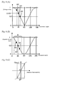
- An example of this voltage value is illustrated in Fig. 6 (A) .
- the voltage value according to an attenuation characteristic of the polarizer 134, is expressed as a value on a curve of a sine wave characteristic (SIN wave).
- the second Faraday rotator 138 (and the permanent magnet 140) particularly provides a 45 degrees as a certain polarization rotation angle to light.
- the voltage value is not a maximum value or a minimum value; the voltage value particularly is 0.707.
- the azimuthal angle is less than 45 degrees. Therefore, the voltage value is larger than 0.707.
- the azimuthal angle is larger than about 45 degrees. Therefore, the voltage value is less than about 0.707.
- the magnetic field sensor 131 changes an amount of light guided to the vibration probe 130 also according to a direction of a magnetic field generated at the solenoidal coil 148.
- a certain non-90n degrees (where n is an integer) polarization rotation angle to the polarization rotation angle of light outgoing from the first Faraday rotator 136 with respect to the polarization axis of the polarizer 134
- a plus or minus sign of a magnetic field that is, a direction of the magnetic field
- the voltage value output from the light receiver circuit 174 is squared by the squaring circuit 176. That is, the squared voltage value output from the squaring circuit 176, as an example, can be illustrated as in Fig. 6 (B) . That is, the voltage value of 0.707 of the state of A3, for which a magnetic field does not exist, becomes a squared voltage value of 0.5.
- the curve expressing a sine wave characteristic can become extremely close to a straight line in a range B centered on a squared voltage value particularly of about 0.5. That is, in the range B particularly centered on an azimuthal angle of about 45 degrees, an azimuthal angle can be obtained in proportion to a squared voltage value. That is, without the need of a complex configuration, the intensity of the magnetic field, including the direction of the magnetic field, can be accurately obtained.
- An output of the squaring circuit 176 is subjected to a sign adjustment, an offset adjustment and a gain adjustment at the offset circuit 178. That is, an output voltage value output from the offset circuit 178, as an example, can be illustrated as in Fig. 6 (C) . Therefore, with a simple configuration, the intensity of the magnetic field, including the direction of the magnetic field, can be easily and accurately obtained. Here, what is detected or determined at the velocity pickup 150 is the velocity. Therefore, according to the voltage value output from the offset circuit 178, representing the intensity of the magnetic field, the velocity of the vibration can be accurately obtained.
- the voltage value output from the offset circuit 178 particularly is subjected to a differentiation operation at the differentiation circuit 180. That is, from the fact that a velocity is obtained at the offset circuit 178, when the differentiation circuit 180 is added, acceleration can be accurately obtained.
- a velocity of a vibration is directly detected.
- the velocity pickup 150 can detect a vibration from a relatively low frequency to a high frequency (from a few Hz to a few kHz). That is, the present embodiment is broadly applicable to earthquake observation, machine vibration, equipment diagnosis, and the like.
- the permanent magnet 140 is used to apply a bias magnetic field to the second Faraday rotator 138. Therefore, there is no need for an external wiring for the vibration probe 130 other than the incident side optical fiber 114. Therefore, there is a great flexibility for the arrangement of the vibration probe 130, and a stable output can be obtained from the vibration probe 130 without externally controlling the second Faraday rotator 138 and the velocity pickup 150.
- the mirror 142 by using the mirror 142 to reflect light, the light travels reciprocally along the respective magnetic field measurement axis O direction of the first Faraday rotator 136 and the second Faraday rotator 138. Therefore, the length of the magnetic field measurement axis O direction of the first Faraday rotator 136 and the second Faraday rotator 138 can be shortened. Therefore, the vibration probe 130 can be made in a small size.
- the mirror 142 functionally is a terminal member of the magnetic field sensor 131. Therefore, no member such as an optical fiber is arranged on the outside of the mirror 142, thereby making installation into the vibration probe 130 easy.
- the vibration axis P of the weight 156 and the movable coil 158, the direction axis of the magnetic field generated at the solenoidal coil 148, and the magnetic field measurement axis O of the magnetic field sensor 131 are identical, and the velocity pickup 150, the solenoidal coil 148, and magnetic field sensor 131, are integrally configured. Therefore, handling of the vibration probe 130 is easy. And, axis alignment of the vibration axis P with respect to an object of a vibration measurement, and assembling of the vibration probe 130 itself, can be easily performed.
- the velocity pickup 150 is at least partly covered with the shield case 152 in order to shield an effect due to a magnetic field external to the velocity pickup 150. Therefore, with respect to the velocity pickup 150, effects of the magnetic field sensor 131, the solenoidal coil 148, and an external magnetic field (including an electromagnetic field), can be reduced or shielded. That is, credibility or reliability of a detected state of a vibration can be enhanced.
- the velocity pickup 150 particularly directly detects a velocity, thereby preventing an offset error due to static gravity.
- the second Faraday rotator 138 particularly is used, and it is desirable that the permanent magnet 140 does not affect the first Faraday rotator 136.
- the present invention is not limited to this. It is also possible that, without using a second Faraday rotator, a permanent magnet is used to apply a bias magnetic field to a first Faraday rotator to provide a certain polarization rotation angle at the first Faraday rotator, and a magnetic field generated at a solenoidal coil is superimposed on the bias magnetic field.
- the optical fiber coupler 116 particularly is used.
- the present invention is not limited to this.
- the processor 170 particularly included the squaring circuit 176 as a squarer, the offset circuit 178 as an offsetter, and the differentiation circuit 180 as a differentiator.
- the present invention is not limited to this. It is also possible to realize a squarer, an offsetter, and a differentiator by performing A/D conversion to an output of a light receiver circuit and performing a software arithmetic processing, without taking the form of circuits.
- the second Faraday rotator 138 particularly is arranged at a subsequent stage of the first Faraday rotator 136, and the permanent magnet 140 is arranged at the external periphery of the second Faraday rotator 138.
- the present invention is not limited to this. It is also possible to arrange a second Faraday rotator at a previous stage of a first Faraday rotator. And, it is also possible to arrange a permanent magnet apart from a second Faraday rotator with respect to the magnetic field detection axis O direction. It is also possible that the shape of the permanent magnet is not a ring shape.
- the weight 156 particularly is supported by the circular plate shaped spring 154, the permanent magnet 160 of the velocity pickup 150 is arranged in a shape following the inner periphery of the movable coil 158, and/or the yoke 164 is arranged in a ring shape on the outside of the movable coil 158.
- the present invention is not limited to this.
- a plate spring 254 to cantilever a movable coil 258, which is integrally configured with a weight.
- the vibration axis P of the weight and the movable coil, the direction axis of the magnetic field generated at the solenoidal coil, and the magnetic field measurement axis O of the magnetic field sensor are identical, and the velocity pickup, the solenoidal coil, and the magnetic field sensor, are integrally configured.
- the present invention is not limited to this. It is also possible to have the magnetic field sensor and the solenoidal coil integrally configured, but the velocity pickup alone separately configured. And, even when these are integrally configured, it is also possible that the axes are not identical, but parallel, or even forming angles therebetween.
- the reflection type vibration probe 130 of the first embodiment is made multiaxial.
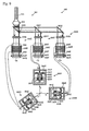
- a schematic configuration of this is as illustrated in Fig. 8 and Fig. 9 .
- Light of a plurality of wavelengths ⁇ 1 - X3 from a light source 304 is guided to an incident side optical fiber (optical fiber) 314.
- an incident side optical fiber optical fiber
- a vibration probe 330 light outgoing from the incident side optical fiber 314 is dispersed into each of the wavelengths ⁇ 1 - ⁇ 3, and is modulated (attenuated) by vibrations detected at the same number of velocity pickups 350X - 350Z as the wavelengths.
- the light outgoing from the incident side optical fiber 314 is dispersed into each of the wavelengths by two dichroic mirrors 333Y and 333Z.
- Specific configuration is explained in the following. Other than related to a part involving multiaxial, explanation is omitted as appropriate.
- the light source 304 particularly includes three LEDs 306X - 306Z, four lenses 308X - 308Z and 312, one mirror 310X and two dichroic mirrors 310Y and 310Z.
- the three LEDs 306X - 306Z respectively emit light of different wavelengths ⁇ 1- X3.
- the light emitted from the LEDs 306X - 306Z is respectively collimated by the lenses 308X - 308Z.
- the collimated light is reflected by the mirror 310X and the dichroic mirrors 310Y and 310Z, and is made incident to the lens 312. Via the lens 312, the light having respectively different wavelengths ⁇ 1- ⁇ 3 is guided by the one incident side optical fiber 314 to the vibration probe 330.
- the vibration probe 330 includes a magnetic field sensor 331, solenoidal coils 348X - 348Z, and velocity pickups 350X - 350Z.
- the magnetic field sensor 331 includes three sensor distal portions 335X - 335Z, having only a lens 332 in common.
- the sensor distal portions 335X - 335Z include, respectively, a mirror 333X or dichroic mirrors 333Y and 333Z, polarizers 334X - 334Z, first Faraday rotators 336X - 336Z, second Faraday rotators 338X - 338Z, permanent magnets 340X - 340Z, and mirrors 342X - 342Z.
- light outgoing from the incident side optical fiber 314 is collimated by the lens 332.
- the collimated light is made incident to the dichroic mirror 333Z.
- the dichroic mirror 333Z reflects light of wavelengths ⁇ 1 and ⁇ 2, and transmits light of wavelength ⁇ 3.
- the light reflected by the dichroic mirror 333Z is made incident to the dichroic mirror 333Y.
- the dichroic mirror 333Y transmits light of wavelength ⁇ 1 and reflects light of wavelength ⁇ 2.
- the light transmitted through the dichroic mirror 333Y is reflected by the mirror 333X.
- the light dispersed by the mirror 333X and the dichroic mirrors 333Y and 333Z is respectively made incident to the mirrors 342X - 342Z via the polarizers 334X - 334Z, the first Faraday rotators 336X - 336Z and the second Faraday rotators 338X - 338Z.
- the light reflected by the mirrors 342X - 342Z is respectively guided to the incident side optical fiber 314 via the mirror 333X and the dichroic mirrors 333Y and 333Z.
- Other configuration and operation of the magnetic field sensor 331 are the same as in the first embodiment, and therefore, the description thereof is not repeated.
- each of the solenoidal coils 348X - 348Z and the velocity pickups 350X - 350Z are the same as in the first embodiment, and therefore, the description thereof is not repeated.
- the velocity pickups 350X - 350Z are fixedly arranged to be perpendicular to each other. Therefore, magnetic field measurement axes Ox - Oz of the magnetic field sensor 331 and vibration axes Px - Pz of the velocity pickups 350X - 350Z respectively are not identical, but are in different arrangement relationship.
- the magnetic field sensor 331 and the solenoidal coils 348X - 348Z are integrally configured, and the velocity pickups 350X - 350Z are integrally configured.
- positional relationship between the magnetic field sensor 331 and the velocity pickups 350X -350Z may be kept fixed, and may also be kept flexibly changeable.
- an optical receiver 320 includes a lens 322, a mirror 324X and dichroic mirrors 324Y and 324Z, and photoelectric sensors 326X - 326Z.
- Light outgoing from an outgoing side optical fiber 318 is collimated by the lens 322, and is dispersed into each of the wavelengths ⁇ 1 - ⁇ 3 by the dichroic mirrors 324Y and 324Z, and the dispersed light is respectively received by the photoelectric sensors 326X - 326Z.
- the light received by the photoelectric sensors 326X - 326Z is photoelectric-converted, and is output as electrical signals to a processor.
- the processor has the same configuration as in the first embodiment, and performs the same operation. Therefore, the description thereof is not repeated. It is also possible to have the same number of processors as the wavelengths and arrange the processors in parallel. It is also possible to share a processor as appropriate for different wavelengths.
- the sensor distal portions 335X - 335Z are respectively provided for each of the wavelengths ⁇ 1 - ⁇ .3, and can be arranged in such a way that the vibration axes Px - Pz of the velocity pickups 350X - 350Z are mutually perpendicular. By doing this, it is possible to measure a state of a three-dimensional vibration. That is, by vector-synthesizing output voltage values Vout obtained with respect to the axes, a direction and a magnitude (of a velocity) of a vibration can be obtained (same with respect to an acceleration of a vibration).
- the magnetic field sensor 331 In making it multiaxial, the magnetic field sensor 331 is used. Therefore, arrangement of the sensor distal portions 335X - 335Z is easy. At the same time, by using the two dichroic mirrors 333Y and 333Z, the vibration probe 330 can be compactly assembled in a synergistic manner. And, the two dichroic mirrors 324Y and 324Z are also used in the optical receiver 320. Therefore, the optical receiver 320 also can be compactly assembled.
- the same configuration as the velocity pickup 150 described in the first embodiment is used for each of the velocity pickups 350X - 350Z.
- the magnetic field sensor is divided into a plurality of sensor distal portions using a mirror and dichroic mirrors, and velocity pickups are provided, having respectively different positional relationships with respect to the sensor distal portions.
- a vibration probe 530 may be configured to have 3 mutually perpendicular probe distal portions 568X - 568Z, which are formed by respectively integrally configuring sensor distal portions 535X - 535Z and velocity pickups 550X - 550Z.
- a lens 532 is provided in common, and the 3 probe distal portions 568X - 568Z are arranged directly mutually perpendicular by using dichroic mirrors 533Y and 533Z.
- the probe distal portions 568X - 568Z magnetic field measurement axes Ox - Oz of the sensor distal portions 535X - 535Z and vibration axes Px - Pz of the velocity pickups 550X - 550Z are respectively identical, and the sensor distal portions 535X - 535Z and the velocity pickups 550X - 550Z are respectively integrally configured using probe cases 566X - 566Z.
- a state of a vibration along 3 axis directions is obtained using 3 wavelengths ⁇ 1 - ⁇ 3.
- the present invention is not limited to this, but is also applicable to a case of a greater number of axes.
- wavelength multiplexing is easy. And, only one optical fiber is required.
- light outgoing from an incident side optical fiber is dispersed into each of the wavelengths ⁇ 1 - ⁇ 3 by two dichroic mirrors.
- the present invention is not limited to this. It is also possible to use an optical element having a different wavelength selectivity in place of a dichroic mirror.
- the present embodiment uses a transmission type magnetic field sensor 631. That is, in place of the second Faraday rotator 138, the permanent magnet 140, the mirror 142 and the polarizer 134 (when a reflected light returns) in the first embodiment, an analyzer 644 is used.
- the analyzer 644 is arranged to have a polarization axis angle different from that of a polarizer 634 (for example, 45 degrees). And, light passing through the analyzer 644 is collected by a lens 646, and is made directly incident to an outgoing side optical fiber 618. That is, the analyzer 644, particularly with a polarization axis 45 degrees different from the polarization axis of the polarizer 634 (providing a polarization rotation angle of 45 degrees), in place of the polarizer 634, passes light outgoing from a first Faraday rotator 636.
- the analyzer 644 further provides as a bias a certain non-90n degrees (where n is an integer) polarization rotation angle (for example, 45 degrees), to the polarization rotation angle of light outgoing from the first Faraday rotator 636, with respect to the polarization axis of the polarizer 634, and, according to the polarization rotation angle, attenuates amount of light guided to an optical receiver.
- a certain non-90n degrees where n is an integer
- polarization rotation angle for example, 45 degrees
- a velocity pickup same as in the first embodiment can be used.
- the outgoing side optical fiber 618 on the velocity pickup side is folded back toward the same direction as an incident side optical fiber 614.
- a magnetic field measurement axis O of the magnetic field sensor 631 and a vibration axis P of a velocity pickup 650 are not identical, but are parallel.
- the magnetic field sensor 631, a solenoidal coil 648, and the velocity pickup 650 are integrally configured.
- the same operation as the optical fiber type vibration meter 100 described in the first embodiment is possible. Further, in the present embodiment, only the first Faraday rotator 636 is used. Therefore, as compared to the first embodiment, it is possible to lower costs. Further, a permanent magnet for applying a bias magnetic field is not used. Therefore, the vibration probe 630 can be configured and arranged without the need of considering an effect due to a permanent magnet on the first Faraday rotator 636.
- the vibration probe 630 using the velocity pickup described in the first embodiment is described.
- the present invention is not limited to this.
- a magnetic field sensor 731 and a velocity pickup 750 may be integrally configured, and may also be configured in a changeable arrangement.
- the certain polarization rotation angle particularly was about 45 degrees.
- the present invention is not limited to this.
- the certain polarization rotation angle is 45 degrees, regardless of a direction of a magnetic field, an intensity of the magnetic field can be accurately obtained within an equal broad range when making a straight-line approximation (for example, in Fig. 6 (B) , azimuthal angles are each within a range of B/2).
- the certain polarization rotation angle which is provided as a bias, is 45 + 90m degrees (where m is an integer).
- n is an integer.
- an amount of light received in a state where a magnetic field does not exist, is not a maximum value or a minimum value on a curve expressing a sine wave characteristic. For this reason, when the direction of the magnetic field changes, the amount of light received (the voltage value, the squared voltage value or the output voltage value) changes. Therefore, the direction of the magnetic field can be determined.
- a polarization plate which was made of a polarizing film that was sandwiched between glasses, particularly was assumed.
- the present invention is not limited to this.
- a polarization beam splitter or a polarization element of a birefringent crystal (a calcite or the like) may also be used.
- a light source a laser diode or an LED particularly was used. However, something else may also be used. In this regard, it is desirable that it emits a light wavelength transparent with respect to the material of a Faraday rotator. For example, it is desirable that it is a light source of a wavelength of about 1 ⁇ m with respect to a YIG crystal.
- the processor particularly included a squaring circuit as a squarer squaring an electrical signal.
- a squaring circuit as a squarer squaring an electrical signal.
- the present invention is not limited to this. It is also possible not to have a squarer.
- the magnetic field sensor particularly changes the amount of light guided to the vibration probe also according to the direction of the magnetic field generated at the solenoidal coil.
- the present invention is not necessarily limited to this.
- the magnetic field sensor particularly included the polarizer linearly polarizing light guided to the vibration probe, and the first Faraday rotator rotating polarization of light passing through the polarizer by an intensity of a magnetic field.
- the present invention is not necessarily limited to this. As far as it is an element that, as a result, attenuates an amount of light by an intensity of a magnetic field, it can be used.
- the velocity pickup particularly had the movable coil, which was connected to the solenoidal coil, and the permanent magnet, which provided a magnetic field to the movable coil.
- the movable coil particularly vibrated with respect to the permanent magnet.
- the present invention is not limited to this.
- a coil, which is fixed on a shield case, is connected to the solenoidal coil, and a permanent magnet, which is supported by a spring, vibrates with respect to the coil.
- the velocity pickup was at least partly covered with the shield case in order to shield an effect due to a magnetic field external to the velocity pickup.
- the present invention is not limited to this. It is also possible not to include a shield case.
Landscapes
- Physics & Mathematics (AREA)
- General Physics & Mathematics (AREA)
- Measurement Of Mechanical Vibrations Or Ultrasonic Waves (AREA)
Abstract
Description
- The present invention relates to an optical fiber type vibration meter having a light source; an optical fiber guiding light from the light source, a vibration probe to which the guided light is made incident; an optical receiver photoelectric-converting light modulated by vibration of a movable member arranged in the vibration probe to output the light as an electrical signal; and a processor processing the electrical signal to output a state of the vibration as an output voltage value. In particular, the present invention relates to an optical fiber type vibration meter capable of high precision measurement. Furthermore, the invention relates to a method of determining or detecting vibration.
- Conventionally, there are various types of vibration meters. For example, the vibration meters can be divided into a group of an optical fiber type and a group of a non-optical fiber type. In a vibration meter of a non-optical fiber type, as disclosed in Mitutoyo, Vibration Pickup, Catalog No. 4351, output from a vibration probe is an electrical signal. Therefore, when a cable from the vibration probe is long, it is susceptible to electromagnetic induction noises. At the same time, transmission loss via a cable cannot be ignored, and it is possible that signal quality may deteriorate.
- On the other hand, a vibration meter of an optical fiber type outputs light from a vibration probe using an optical fiber as a transmission path (for example, Japanese Patent No.
HEI 3-22595 B2 - However, the optical fiber type vibration meter disclosed in Japanese Patent No.
HEI 3-22595 B2 HEI 3-22595 B2 - As solutions to this problem, passing an acceleration output through a high-pass filter, removing an average value of data, electrically zero-setting an acceleration output, and the like, have been considered. However, for the former two, when it is an asymmetric vibration or when an average data length is not an integral multiple of a vibration wavelength, an error remains. For the latter, there is a problem that it is not applicable in a situation where a state of zero vibration cannot be ensured. Further, in order to perform these processes, there is a possibility that a processor processing a signal from a vibration probe becomes complex.
- The present invention is devised to solve the above-described problem. An advantage of the present invention is to provide an optical fiber type vibration meter and detection method capable of high precision measurement without the need of a complex configuration, while relying on the advantage of using an optical fiber.
This object is solved according to the invention by the features of the independent claim. Preferred embodiments of the invention are subject of the dependent claims. - One aspect of the present invention is an optical fiber type vibration meter having a light source; an optical fiber guiding light from the light source; a vibration probe to which the guided light is made at least partly incident; an optical receiver photoelectric-converting light modulated by a vibration of a movable member arranged in the vibration probe to output the light as an electrical signal; a processor processing the electrical signal to output a state of the vibration as an output voltage value; a velocity pickup converting a velocity of the movable member arising from the vibration of the movable member into an electrical current; a solenoidal coil generating a magnetic field by the electrical current; and a magnetic field sensor attenuating an amount of light guided to the vibration probe according to an intensity of the magnetic field.
- According to another aspect of the present invention, the magnetic field sensor changes an amount of light guided to the vibration probe also according to a direction of a magnetic field generated by the solenoidal coil.
- According to another aspect of the present invention, the magnetic field sensor has a polarizer linearly polarizing light guided to the vibration probe; and at least one Faraday rotator rotating polarization of light passing through the polarizer by the intensity of the magnetic field.
- According to another aspect of the present invention, the velocity pickup has a coil being connected to the solenoidal coil; and a permanent magnet providing a magnetic field to the coil, and the coil relatively vibrates with respect to the permanent magnet.
- According to another aspect of the present invention, the velocity pickup is covered with a shield case for shielding an effect of a magnetic field external to the velocity pickup.
- According to another aspect of the present invention, in the vibration probe, a vibration axis of the movable member, a direction axis of a magnetic field generated by the solenoidal coil and a magnetic field measurement axis of the magnetic field sensor are substantially identical or substantially parallel, and the velocity pickup, the solenoidal coil and the magnetic field sensor are integrally configured.
- According to another aspect of the present invention, the light source guides light of a plurality of wavelengths to the optical fiber, and, at the vibration probe, light outgoing from the optical fiber is dispersed into each of the wavelengths, and is modulated by the vibration detected by a same number of the velocity pickups as the wavelengths.
- According to another aspect of the present invention, the processor has a squarer squaring the electrical signal.
- According to another aspect of the present invention, the processor has a differentiator, and outputs as the output voltage value an acceleration representing a state of the vibration.
Another aspect of the invention is a method of detecting or determining a vibration, comprising the following steps: generating light and at least partly guiding the light onto a vibration probe; photoelectric-converting light by means of an optical receiver while modulating it by a vibration of a movable member located in the vibration probe to output the light as an electrical signal; processing the electrical signal to output a state of the vibration as an output voltage value;converting a velocity of the movable member resulting from the vibration of the movable member into an electrical current by means of a velocity pickup; generating a magnetic field by the electrical current; and attenuating an amount of light guided to the vibration probe according to an intensity of the magnetic field.
According to another aspect of the present invention, the method further comprises changing an amount of light guided to the vibration probe also according to a direction of the generated magnetic field.
According to another aspect of the present invention, the method further comprises linearly polarizing light guided to the vibration probe by means of a polarizer; and rotating polarization of light passing through the polarizer by the intensity of the magnetic field.
According to another aspect of the present invention, in the vibration probe, a vibration axis of the movable member, a direction axis of the generated magnetic field and a magnetic field measurement axis of a magnetic field sensor are one of being substantially identical and being substantially parallel.
According to another aspect of the present invention, light of a plurality of wavelengths is guided and is dispersed at the vibration probe into each of the wavelengths, and is modulated by the vibration detected by a same number of velocity pickups as the wavelengths.
According to another aspect of the present invention, processing the electrical signal comprises squaring the electrical signal and/or processing the electrical signal comprises differentiating so as to output as the output voltage value an acceleration representing a state of the vibration. - According to the present invention, while relying on the advantage of using an optical fiber, high precision measurement is possible without the need of a complex configuration. That is, it is possible for a long distance signal transmission maintaining signal quality as output from a vibration probe, without the need of power feeding during the transmission. At the same time, heat generation is also reduced, and it can be made slim and light-weighted. Further, high explosion proof can be maintained. At the same time, an offset error due to static gravity can be prevented.
- The present invention is further described in the detailed description which follows, in reference to the noted plurality of drawings by way of non-limiting examples of exemplary embodiments of the present invention, in which like reference numerals represent similar parts throughout the several views of the drawings.. It should be understood that even though embodiments are separately described, single features thereof may be combined to additional embodiments.
-
Fig. 1 is an overall pattern diagram of an optical fiber type vibration meter according to a first embodiment of the present invention; -
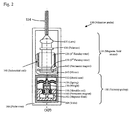
Fig. 2 is an enlarged pattern diagram of a vibration probe of the optical fiber type vibration meter according to the first embodiment of the present invention; -
Fig. 3 is an enlarged pattern diagram of a magnetic field sensor of the vibration probe of the optical fiber type vibration meter according to the first embodiment of the present invention; -
Fig. 4 is a pattern diagram explaining a relationship between a polarization axis of a polarizer and a transmitted light amount; -
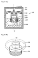
Fig. 5 is an enlarged pattern diagram of a velocity pickup according to the first embodiment of the present invention; -
Fig. 6 is pattern diagram expressing a state of a signal after an optical receiver of the vibration probe according to the first embodiment of the present invention; -
Fig. 7 is an enlarged pattern diagram of a velocity pickup according to a second embodiment of the present invention; -
Fig. 8 is a schematic pattern diagram of a detector of an optical fiber type vibration meter according to a third embodiment of the present invention; -
Fig. 9 is an enlarged pattern diagram of a vibration probe of the optical fiber type vibration meter according to the third embodiment of the present invention; -
Fig. 10 is an enlarged pattern diagram of a velocity pickup according to a fourth embodiment of the present invention; -
Fig. 11 is an enlarged pattern diagram of a vibration probe according to a fifth embodiment of the present invention; -
Fig. 12 is an enlarged pattern diagram of a magnetic field sensor according to a sixth embodiment of the present invention; -
Fig. 13 is an enlarged pattern diagram of a vibration probe according to the sixth embodiment of the present invention; and -
Fig. 14 is an enlarged pattern diagram of a vibration probe according to a seventh embodiment of the present invention. - The particulars shown herein are by way of example and for purposes of illustrative discussion of the embodiments of the present invention only and are presented in the cause of providing what is believed to be the most useful and readily understood description of the principles and conceptual aspects of the present invention. In this regard, no attempt is made to show structural details of the present invention in more detail than is necessary for the fundamental understanding of the present invention, the description is taken with the drawings making apparent to those skilled in the art how the forms of the present invention may be embodied in practice.
- In the following, with reference to the drawings, an example of an embodiment of the present invention is explained in detail.
- First, an overview of an optical fiber type vibration meter according to a first embodiment is explained using
Fig. 1 andFig. 2 . - As illustrated in
Fig. 1 andFig. 2 , an optical fibertype vibration meter 100 has alight source 104; an incident side optical fiber 114 (as a particular optical fiber) guiding light from thelight source 104; avibration probe 130 to which the guided light is made incident; anoptical receiver 120 photoelectric-converting light modulated by vibration of aweight 156 and/or a movable coil 158 (as a particular movable member) arranged in thevibration probe 130 to output the light as an electrical signal; and/or aprocessor 170 processing the electrical signal to output a state (e.g. velocity) of the vibration as an output voltage value Vout. - As illustrated in
Fig. 2 , the optical fibertype vibration meter 100 includes avelocity pickup 150 converting a velocity of theweight 156 and/or themovable coil 158 arising from the vibration of theweight 156 and/or themovable coil 158 into an electrical current (which particularly is proportional to the velocity); asolenoidal coil 148 generating a magnetic field by the electrical current; and/or amagnetic field sensor 131 attenuating an amount of light guided to thevibration probe 130 according to an intensity of the magnetic field. - In the following, a configuration of the optical fiber
type vibration meter 100 is explained in more detail based onFig. 1 ,Fig. 2 andFig. 5 . - As illustrated in
Fig. 1 , the optical fibertype vibration meter 100 has adetector 102 and theprocessor 170. As illustrated inFig. 1 , thedetector 102 includes thelight source 104; the incident sideoptical fiber 114; anoptical fiber coupler 116; an outgoing sideoptical fiber 118; theoptical receiver 120; and thevibration probe 130. - As illustrated in
Fig. 1 , thelight source 104 particularly has a laser diode, an LED, and the like. The incident sideoptical fiber 114 is connected to thelight source 104, and at least partly guides light from thelight source 104 to thevibration probe 130. It is also possible that a part of the light guided to thevibration probe 130 is photoelectric-converted by another optical receiver (not shown in the figure) and its output is monitored. According to the monitored output, an electrical signal output from theoptical receiver 120 particularly is made a normalized voltage value at alight receiver circuit 174. Theoptical fiber coupler 116 particularly is formed by fusion joining the incident sideoptical fiber 114 and the outgoing sideoptical fiber 118. Light returning from thevibration probe 130 to the incident sideoptical fiber 114 at least partly is branched to the outgoing sideoptical fiber 118. The outgoing sideoptical fiber 118 is connected to theoptical receiver 120. At theoptical receiver 120, an incoming light, passing through the outgoing sideoptical fiber 118, at least partly is photoelectric-converted and output to theprocessor 170 as an electrical signal. For the incident sideoptical fiber 114 and/or the outgoing sideoptical fiber 118, a single mode fiber, a multimode fiber, a polarization-preserving type optical fiber, and the like, can be used. - As illustrated in
Fig. 2 , thevibration probe 130 includes themagnetic field sensor 131, thesolenoidal coil 148, and thevelocity pickup 150. These are integrally configured in aprobe case 166. In this case, a vibration axis P of theweight 156 and/or themovable coil 158, a direction axis of the magnetic field generated at thesolenoidal coil 148 and a magnetic field measurement axis O of themagnetic field sensor 131 particularly are identical. - As illustrated in
Fig. 3 , themagnetic field sensor 131 includes alens 132, a polarizer 134 (polarization plate), afirst Faraday rotator 136, asecond Faraday rotator 138, apermanent magnet 140, and amirror 142. - As illustrated in
Fig. 3 , thelens 132 collimates light guided by the incident sideoptical fiber 114, and makes it incident to thepolarizer 134. Thepolarizer 134 linearly polarizes the light outgoing from the incident sideoptical fiber 114 and being collimated. The first Faraday rotator 136 (as a particular Faraday rotator) rotates a transmission axis (called a polarization axis) of (performs polarization rotation to) the linearly polarized light (also simply called linear polarization) that has passed through thepolarizer 134, by an intensity of a magnetic field in the magnetic field measurement axis direction O. Thesecond Faraday rotator 138 is arranged at a subsequent stage of thefirst Faraday rotator 136, separately from thefirst Faraday rotator 136. At an external periphery of thesecond Faraday rotator 138, the ring-shapedpermanent magnet 140 is arranged. Thispermanent magnet 140 applies a bias magnetic field to thesecond Faraday rotator 138. Thereby, thesecond Faraday rotator 138 further provides a polarization rotation angle particularly of about 22.5 degrees to a polarization rotation angle of the light outgoing from thefirst Faraday rotator 136. - As illustrated in
Fig. 3 , at an end of themagnetic field sensor 131, themirror 142 is arranged. Themirror 142 substantially vertically reflects the light that has been polarization-rotated by thesecond Faraday rotator 138. The light reflected by themirror 142 is again provided with a polarization rotation angle particularly of about 22.5 degrees at thesecond Faraday rotator 138. That is, with respect to the polarization axis of thepolarizer 134, thesecond Faraday rotator 138 further provides a certain polarization rotation angle particularly of about 45 degrees to the polarization rotation angle of the light outgoing from thefirst Faraday rotator 136. And, the light reflected by themirror 142 is made incident to thepolarizer 134. For both thefirst Faraday rotator 136 and thesecond Faraday rotator 138, a material having the Faraday effect (particularly mainly a YIG crystal and the like) can be used. In this case, a YIG crystal having a large Verdet constant is more desirable. - Here,
Fig. 4 is used to explain that, with respect to the polarization axis of thepolarizer 134, thesecond Faraday rotator 138 further provides a certain (predetermined or predeterminable) polarization rotation angle particularly of about 45 degrees to the polarization rotation angle of the light outgoing from thefirst Faraday rotator 136. In this regard, it is assumed for the present explanation that a component of light in the polarization axis direction transmits 100% at the polarizer 134 (a loss other than due to a polarization direction is ignored). - In
Fig. 4 , when a polarization axis Q of thepolarizer 134 and a linear polarization A1 are substantially parallel to each other (with respect to the polarization axis Q, a polarization rotation angle of the linear polarization (called an azimuthal angle) particularly is 0 degree), the linear polarization A1 particularly transmits 100% with respect to thepolarizer 134. However, when the polarization axis Q and a linear polarization A5 are perpendicular to each other (azimuthal angle is 90 degrees), the linear polarization A5 particularly does not transmit at all (0% transmission) with respect to thepolarizer 134. As an intermediate case, when the polarization axis Q and a linear polarization A3 particularly form a 45 degree angle (azimuthal angle is about 45 degrees), the linear polarization A3 particularly transmits 70.7% (according to cos(45 degrees) = 0.707) with respect to thepolarizer 134. That is, in the present embodiment, even without a magnetic field, thesecond Faraday rotator 138 provides a polarization rotation angle particularly of about 45 degrees to the linear polarization by thepolarizer 134. Therefore, even without a magnetic field, an amount of light returning to the incident sideoptical fiber 114 via thepolarizer 134 is attenuated (modulated) to only 70.7% of the amount of light of the linear polarization outgoing from thepolarizer 134. - In order to reduce an effect of the
permanent magnet 140 on thefirst Faraday rotator 136, a magnetic shield may be provided at an external periphery of thepermanent magnet 140. For example, the magnetic shield can be configured to cover peripheries of thesecond Faraday rotator 138, thepermanent magnet 140 and themirror 142, and have an opening only at a light passing section. As the magnetic shield, for example, a perm alloy and the like can be used. Without providing a magnetic shield, it is also possible to arrange thepermanent magnet 140 and thefirst Faraday rotator 136 sufficiently separated so as to avoid creating a magnetic effect on thefirst Faraday rotator 136 by thepermanent magnet 140. - The Faraday effect is a phenomenon that a polarization plan rotates in proportion to an intensity of a magnetic field. With respect to the Faraday effect, equation (1) holds:

- Here the symbol Φ is a Faraday rotation angle (a polarization rotation angle of light). The symbol V is a Verdet constant and varies according to the material of a Faraday rotator. The symbol H represents an intensity of a magnetic field along a propagation direction of light (magnetic field detection axis O direction). The symbol L is a length of the magnetic field detection axis O direction of a Faraday rotator.
- Here, a polarization rotation of a (linearly polarized) light occurs when there exists a component of a magnetic field along the propagation direction of the light (the magnetic field detection axis O direction). In detail, in the Faraday effect, when the direction of a magnetic field is the same as the propagation direction of light, the polarization of the light rotates in a rotating direction of a right-handed screw with respect to the propagation direction of the light. When the direction of the magnetic field is substantially opposite to the propagation direction of the light, the polarization of the light rotates in a rotating direction of a left-handed screw with respect to the propagation direction of the light.
- As illustrated in
Fig. 2 andFig. 3 , thesolenoidal coil 148 is a coil arranged at an external periphery of thefirst Faraday rotator 136. Thesolenoidal coil 148 is electrically connected to themovable coil 158 of the velocity pickup 150 (to be described later). - A magnetic flux density generated at the
solenoidal coil 148 is proportional to an electrical current, according to the Ampere's law, and the relation of equation (2) holds. And, a magnetic flux density is proportional to an intensity of a magnetic field.
- Here, the
symbol B 1 is a magnetic flux density along an axis direction inside thesolenoidal coil 148. The symbol n1 is a number of coil turns per unit length in the axis direction of thesolenoidal coil 148. The symbol L1 is a length in the axis direction of thesolenoidal coil 148. The symbol I is an electrical current flowing in thesolenoidal coil 148. - As illustrated in
Fig. 2 andFig. 5 , thevelocity pickup 150 particularly includes aspring 154, theweight 156, themovable coil 158, apermanent magnet 160, and/or ayoke 164. These are covered with ashield case 152 in order to shield an effect due to a magnetic field external to thevelocity pickup 150. That is, in the present embodiment, theshield case 152 can also shield effects due to a magnetic field of thepermanent magnet 140 of themagnetic field sensor 131 and a magnetic field generated at thesolenoidal coil 148. - As illustrated in
Fig. 2 andFig. 5 , an external periphery of thespring 154 is fixed on theshield case 152. Thespring 154 supports theweight 156 with its center, allowing theweight 156 to displace substantially along the vibration axis P (diaphragm construction). A concave portion is formed on a downside of theweight 156. And, along a circumferential direction of the concave portion, the ring-shapemovable coil 158 particularly is integrally fixed to the downside of theweight 156. Themovable coil 158 is electrically connected to thesolenoidal coil 148 through a through-hole 152A formed on theshield case 152, to form a closed circuit. That is, themovable coil 158 is a coil connected to thesolenoidal coil 148. On the inner side of themovable coil 158, thepermanent magnet 160, shaped following the inner side of themovable coil 158, is arranged. - A clearance between an external periphery of the
permanent magnet 160 and an inner periphery of themovable coil 158 is uniform in a circumferential direction. Thepermanent magnet 160 is fixed on theyoke 164 surrounding an external periphery of themovable coil 158 with a predetermined or predeterminable clearance G. For this reason, magnetic flux (magnetic field) is generated between thepermanent magnet 160 and theyoke 164. Therefore, it is in a state in which thepermanent magnet 160 is applying a magnetic field to themovable coil 158. And, with respect to thepermanent magnet 160, themovable coil 158 vibrates. That is, in thevelocity pickup 150, a velocity of a vibration is (directly) detected. According to such a principle, thevelocity pickup 150 can detect or determine a vibration from a relatively low frequency to a high frequency (from a few Hz to a few kHz). - The
symbol 162 is for a magnetic fluid, which has a function of damping a motion of themovable coil 158. Using themagnetic fluid 162 allows stabilizing a damping material between thepermanent magnet 160 and theyoke 164. However, it is not necessary that a damping material has to be a magnetic fluid. For example, it is also possible to use a gas, a liquid, and the like, such as an air, a water and/or an oil. - An output electrical current of the
velocity pickup 150, according to the Fleming's right hand rule, is proportional to a velocity component of a vibration, and equation (3) holds.
- Here, the symbol I is an electrical current flowing in the
movable coil 158. The symbol B2 is a magnetic flux density in the clearance G between thepermanent magnet 160 and theyoke 164. The symbol L2 is a length of themovable coil 158 cutting across the magnetic flux. - As illustrated in
Fig. 1 , theprocessor 170 includes alight emitting circuit 172, thelight receiver circuit 174, a squaring circuit 176 (which is a squarer), and an offset circuit 178 (which is an offsetter). Further, theprocessor 170 may include a differentiation circuit 180 (which is a differentiator). - As illustrated in
Fig. 1 , thelight emitting circuit 172 allows thelight source 104 to provide a stable emission of light. Thelight receiver circuit 174 outputs an electrical signal output from theoptical receiver 120 as a normalized voltage value to the squaringcircuit 176. The squaringcircuit 176 squares the voltage value output from thelight receiver circuit 174 and outputs a squared voltage value. Here, when the normalized voltage value particularly is 70.7% with respect to a normalization value, the squared voltage value output from the squaringcircuit 176 is 0.5 (= 0.7072; a value of 50% with respect to a normalized squared voltage value). The offsetcircuit 178 uses a squared voltage value of 0.5 as an offset, performs a gain adjustment, inverts a sign of plus or minus when needed, and outputs the value as an output voltage value Vout. That is, the output voltage value Vout corresponds to a velocity output of a vibration. Thedifferentiation circuit 180 performs differentiation of the output voltage value Vout of the offsetcircuit 178. This processing, since the output voltage value Vout particularly corresponds to or depends on a velocity of a vibration, is added when an acceleration output of a vibration is desired (in that case, it is also possible for the acceleration output to be an output voltage value). - Next, operation of the optical fiber
type vibration meter 100 of the present embodiment is explained mainly usingFig. 1 andFig. 2 . - When the
vibration probe 130 vibrates along the vibration axis P direction, theweight 156 of thevelocity pickup 150 vibrates with respect to theshield case 152. On theshield case 152, thepermanent magnet 160 and theyoke 164 are fixed. Meanwhile, on theweight 156, themovable coil 158 is fixed. Therefore, due to the vibration of theweight 156, themovable coil 158 cuts across the magnetic flux occurring between thepermanent magnet 160 andyoke 164. Therefore, according to the Fleming's right hand rule, an electrical current proportional to a velocity of themovable coil 158 is generated in themovable coil 158. - The electrical current generated in the
movable coil 158 flows directly to thesolenoidal coil 148. Then, according to the Ampere's law, magnetic flux (magnetic field) is generated inside thesolenoidal coil 148. That is, inside thefirst Faraday rotator 136, a magnetic field along the magnetic field measurement axis O direction is generated. - Meanwhile, light is emitted from the
light source 104 by thelight emitting circuit 172. The light emitted from thelight source 104 is guided by the incident sideoptical fiber 114. - The guided light is emitted from the incident side
optical fiber 114, and is collimated by thelens 132. The collimated light is made incident to thepolarizer 134, and is linearly polarized. The linearly polarized light is polarization-rotated at thefirst Faraday rotator 136 by an intensity of the magnetic field generated along the magnetic field measurement axis O direction. The polarization-rotated light is further polarization-rotated for 22.5 degrees at thesecond Faraday rotator 138. Then, the light is (particularly vertically) reflected by themirror 142, and is again further polarization-rotated for 22.5 degrees at thesecond Faraday rotator 138. That is, thesecond Faraday rotator 138 provides a certain polarization rotation angle particularly of total 45 degrees. The light passing through thesecond Faraday rotator 138 is further polarization-rotated also at thefirst Faraday rotator 136. The light is made incident to thepolarizer 134, and, according to an azimuthal angle with respect to the polarization axis of thepolarizer 134, attenuates to pass through (being modulated). - The attenuated (modulated) light is again returning to the incident side
optical fiber 114 at thelens 132. That is, in themagnetic field sensor 131, according to the intensity of the magnetic field generated at thesolenoidal coil 148, the light guided to thevibration probe 130 is attenuated and then returned. Via theoptical fiber coupler 116, the returning light is guided by the outgoing sideoptical fiber 118 to theoptical receiver 120. - The
optical receiver 120 performs a photoelectric conversion in proportion to or depending on the amount of the returning light (optical fiber feedback light amount) and outputs an electrical signal. The electrical signal is output by thelight receiver circuit 174 as a normalized voltage value. An example of this voltage value is illustrated inFig. 6 (A) . The voltage value, according to an attenuation characteristic of thepolarizer 134, is expressed as a value on a curve of a sine wave characteristic (SIN wave). In the case of A3, where a magnetic field does not exist, the second Faraday rotator 138 (and the permanent magnet 140) particularly provides a 45 degrees as a certain polarization rotation angle to light. Therefore, for an azimuthal angle of 45 degrees as in a state of A3, for which a magnetic field does not exist, the voltage value is not a maximum value or a minimum value; the voltage value particularly is 0.707. In the case of A2, where a magnetic field is minus, the azimuthal angle is less than 45 degrees. Therefore, the voltage value is larger than 0.707. In an opposite manner, in the case of A4, where a magnetic field is plus, the azimuthal angle is larger than about 45 degrees. Therefore, the voltage value is less than about 0.707. - That is, the
magnetic field sensor 131 changes an amount of light guided to thevibration probe 130 also according to a direction of a magnetic field generated at thesolenoidal coil 148. In other words, by providing, as a bias, a certain non-90n degrees (where n is an integer) polarization rotation angle to the polarization rotation angle of light outgoing from thefirst Faraday rotator 136 with respect to the polarization axis of thepolarizer 134, a plus or minus sign of a magnetic field (that is, a direction of the magnetic field) can be easily determined from an voltage value in proportion to the amount of light received. - The voltage value output from the
light receiver circuit 174 is squared by the squaringcircuit 176. That is, the squared voltage value output from the squaringcircuit 176, as an example, can be illustrated as inFig. 6 (B) . That is, the voltage value of 0.707 of the state of A3, for which a magnetic field does not exist, becomes a squared voltage value of 0.5. At the same time, the curve expressing a sine wave characteristic can become extremely close to a straight line in a range B centered on a squared voltage value particularly of about 0.5. That is, in the range B particularly centered on an azimuthal angle of about 45 degrees, an azimuthal angle can be obtained in proportion to a squared voltage value. That is, without the need of a complex configuration, the intensity of the magnetic field, including the direction of the magnetic field, can be accurately obtained. - An output of the squaring
circuit 176 is subjected to a sign adjustment, an offset adjustment and a gain adjustment at the offsetcircuit 178. That is, an output voltage value output from the offsetcircuit 178, as an example, can be illustrated as inFig. 6 (C) . Therefore, with a simple configuration, the intensity of the magnetic field, including the direction of the magnetic field, can be easily and accurately obtained. Here, what is detected or determined at thevelocity pickup 150 is the velocity. Therefore, according to the voltage value output from the offsetcircuit 178, representing the intensity of the magnetic field, the velocity of the vibration can be accurately obtained. - The voltage value output from the offset
circuit 178 particularly is subjected to a differentiation operation at thedifferentiation circuit 180. That is, from the fact that a velocity is obtained at the offsetcircuit 178, when thedifferentiation circuit 180 is added, acceleration can be accurately obtained. - In the present embodiment, a velocity of a vibration is directly detected. The
velocity pickup 150 can detect a vibration from a relatively low frequency to a high frequency (from a few Hz to a few kHz). That is, the present embodiment is broadly applicable to earthquake observation, machine vibration, equipment diagnosis, and the like. - Further, in the present embodiment, the
permanent magnet 140 is used to apply a bias magnetic field to thesecond Faraday rotator 138. Therefore, there is no need for an external wiring for thevibration probe 130 other than the incident sideoptical fiber 114. Therefore, there is a great flexibility for the arrangement of thevibration probe 130, and a stable output can be obtained from thevibration probe 130 without externally controlling thesecond Faraday rotator 138 and thevelocity pickup 150. - Further, in the present embodiment, by using the
mirror 142 to reflect light, the light travels reciprocally along the respective magnetic field measurement axis O direction of thefirst Faraday rotator 136 and thesecond Faraday rotator 138. Therefore, the length of the magnetic field measurement axis O direction of thefirst Faraday rotator 136 and thesecond Faraday rotator 138 can be shortened. Therefore, thevibration probe 130 can be made in a small size. Further, themirror 142 functionally is a terminal member of themagnetic field sensor 131. Therefore, no member such as an optical fiber is arranged on the outside of themirror 142, thereby making installation into thevibration probe 130 easy. - Further, in the present embodiment, in the
vibration probe 130, the vibration axis P of theweight 156 and themovable coil 158, the direction axis of the magnetic field generated at thesolenoidal coil 148, and the magnetic field measurement axis O of themagnetic field sensor 131, particularly are identical, and thevelocity pickup 150, thesolenoidal coil 148, andmagnetic field sensor 131, are integrally configured. Therefore, handling of thevibration probe 130 is easy. And, axis alignment of the vibration axis P with respect to an object of a vibration measurement, and assembling of thevibration probe 130 itself, can be easily performed. - Further, in the present embodiment, the
velocity pickup 150 is at least partly covered with theshield case 152 in order to shield an effect due to a magnetic field external to thevelocity pickup 150. Therefore, with respect to thevelocity pickup 150, effects of themagnetic field sensor 131, thesolenoidal coil 148, and an external magnetic field (including an electromagnetic field), can be reduced or shielded. That is, credibility or reliability of a detected state of a vibration can be enhanced. - That is, in the present embodiment, while relying on the advantage of using an optical fiber, high precision measurement is possible without the need of a complex configuration. That is, it is possible for a long distance signal transmission maintaining signal quality as output from the
vibration probe 130, without the need of power feeding during the transmission. At the same time, heat generation is also reduced, and it can be made slim and light-weighted. Further, high explosion proof can be maintained. At the same time, thevelocity pickup 150 particularly directly detects a velocity, thereby preventing an offset error due to static gravity. - In the present embodiment, the
second Faraday rotator 138 particularly is used, and it is desirable that thepermanent magnet 140 does not affect thefirst Faraday rotator 136. However, the present invention is not limited to this. It is also possible that, without using a second Faraday rotator, a permanent magnet is used to apply a bias magnetic field to a first Faraday rotator to provide a certain polarization rotation angle at the first Faraday rotator, and a magnetic field generated at a solenoidal coil is superimposed on the bias magnetic field. - Further, in the present embodiment, the
optical fiber coupler 116 particularly is used. However, the present invention is not limited to this. For example, it is also possible to use a beam splitter that is not of an optical fiber type. - Further, in the present embodiment, the
processor 170 particularly included thesquaring circuit 176 as a squarer, the offsetcircuit 178 as an offsetter, and thedifferentiation circuit 180 as a differentiator. However, the present invention is not limited to this. It is also possible to realize a squarer, an offsetter, and a differentiator by performing A/D conversion to an output of a light receiver circuit and performing a software arithmetic processing, without taking the form of circuits. - Further, in the present embodiment, the
second Faraday rotator 138 particularly is arranged at a subsequent stage of thefirst Faraday rotator 136, and thepermanent magnet 140 is arranged at the external periphery of thesecond Faraday rotator 138. However, the present invention is not limited to this. It is also possible to arrange a second Faraday rotator at a previous stage of a first Faraday rotator. And, it is also possible to arrange a permanent magnet apart from a second Faraday rotator with respect to the magnetic field detection axis O direction. It is also possible that the shape of the permanent magnet is not a ring shape. - Further, in the present embodiment, the
weight 156 particularly is supported by the circular plate shapedspring 154, thepermanent magnet 160 of thevelocity pickup 150 is arranged in a shape following the inner periphery of themovable coil 158, and/or theyoke 164 is arranged in a ring shape on the outside of themovable coil 158. However, the present invention is not limited to this. For example, as in avelocity pickup 250 according to a second embodiment of the present invention as illustrated inFig. 7 , it is also possible to use aplate spring 254 to cantilever amovable coil 258, which is integrally configured with a weight. And, it is also possible to fix two squarepermanent magnets 260 on outer portions of ayoke 264 in such a way that thepermanent magnets 260 face a portion of theyoke 264 inside themovable coil 258. Of course, it is also possible to arrange permanent magnets both inside and outside a movable coil. In that case, it is not limited to a bi-directional arrangement. And, a magnetic pole may be in any direction. - Further, in the above-described embodiment, in the vibration probe, the vibration axis P of the weight and the movable coil, the direction axis of the magnetic field generated at the solenoidal coil, and the magnetic field measurement axis O of the magnetic field sensor, are identical, and the velocity pickup, the solenoidal coil, and the magnetic field sensor, are integrally configured. However, the present invention is not limited to this. It is also possible to have the magnetic field sensor and the solenoidal coil integrally configured, but the velocity pickup alone separately configured. And, even when these are integrally configured, it is also possible that the axes are not identical, but parallel, or even forming angles therebetween.
- Next, a third embodiment of the present invention is explained using
Fig. 8 andFig. 9 . - In the present embodiment, the reflection
type vibration probe 130 of the first embodiment is made multiaxial. A schematic configuration of this is as illustrated inFig. 8 andFig. 9 . Light of a plurality of wavelengths λ1 - X3 from alight source 304 is guided to an incident side optical fiber (optical fiber) 314. At avibration probe 330, light outgoing from the incident sideoptical fiber 314 is dispersed into each of the wavelengths λ1 - λ3, and is modulated (attenuated) by vibrations detected at the same number ofvelocity pickups 350X - 350Z as the wavelengths. In this case, the light outgoing from the incident sideoptical fiber 314 is dispersed into each of the wavelengths by twodichroic mirrors - As illustrated in
Fig. 8 , thelight source 304, for example, particularly includes threeLEDs 306X - 306Z, fourlenses 308X - 308Z and 312, onemirror 310X and twodichroic mirrors LEDs 306X - 306Z respectively emit light of different wavelengths λ1- X3. The light emitted from theLEDs 306X - 306Z is respectively collimated by thelenses 308X - 308Z. The collimated light is reflected by themirror 310X and thedichroic mirrors lens 312. Via thelens 312, the light having respectively different wavelengths λ1- λ3 is guided by the one incident sideoptical fiber 314 to thevibration probe 330. - As illustrated in
Fig. 9 , thevibration probe 330 includes amagnetic field sensor 331,solenoidal coils 348X - 348Z, andvelocity pickups 350X - 350Z. - As illustrated in
Fig. 9 , themagnetic field sensor 331 includes three sensordistal portions 335X - 335Z, having only alens 332 in common. The sensordistal portions 335X - 335Z include, respectively, amirror 333X ordichroic mirrors first Faraday rotators 336X - 336Z,second Faraday rotators 338X - 338Z,permanent magnets 340X - 340Z, and mirrors 342X - 342Z. - As illustrated in
Fig. 9 , light outgoing from the incident sideoptical fiber 314 is collimated by thelens 332. The collimated light is made incident to thedichroic mirror 333Z. Here, thedichroic mirror 333Z reflects light of wavelengths λ1 and λ2, and transmits light of wavelength λ3. The light reflected by thedichroic mirror 333Z is made incident to thedichroic mirror 333Y. Thedichroic mirror 333Y transmits light of wavelength λ1 and reflects light of wavelength λ2. The light transmitted through thedichroic mirror 333Y is reflected by themirror 333X. The light dispersed by themirror 333X and thedichroic mirrors mirrors 342X - 342Z via thepolarizers 334X - 334Z, thefirst Faraday rotators 336X - 336Z and thesecond Faraday rotators 338X - 338Z. The light reflected by themirrors 342X - 342Z is respectively guided to the incident sideoptical fiber 314 via themirror 333X and thedichroic mirrors magnetic field sensor 331 are the same as in the first embodiment, and therefore, the description thereof is not repeated. - In
Fig. 9 , configuration and operation of each of the solenoidal coils 348X - 348Z and thevelocity pickups 350X - 350Z are the same as in the first embodiment, and therefore, the description thereof is not repeated. However, thevelocity pickups 350X - 350Z are fixedly arranged to be perpendicular to each other. Therefore, magnetic field measurement axes Ox - Oz of themagnetic field sensor 331 and vibration axes Px - Pz of thevelocity pickups 350X - 350Z respectively are not identical, but are in different arrangement relationship. In this case, themagnetic field sensor 331 and the solenoidal coils 348X - 348Z are integrally configured, and thevelocity pickups 350X - 350Z are integrally configured. On the other hand, positional relationship between themagnetic field sensor 331 and thevelocity pickups 350X -350Z may be kept fixed, and may also be kept flexibly changeable. - As illustrated in
Fig. 8 , anoptical receiver 320 includes alens 322, amirror 324X anddichroic mirrors photoelectric sensors 326X - 326Z. Light outgoing from an outgoing sideoptical fiber 318 is collimated by thelens 322, and is dispersed into each of the wavelengths λ1 - λ3 by thedichroic mirrors photoelectric sensors 326X - 326Z. The light received by thephotoelectric sensors 326X - 326Z is photoelectric-converted, and is output as electrical signals to a processor. - The processor has the same configuration as in the first embodiment, and performs the same operation. Therefore, the description thereof is not repeated. It is also possible to have the same number of processors as the wavelengths and arrange the processors in parallel. It is also possible to share a processor as appropriate for different wavelengths.
- As described above, the sensor
distal portions 335X - 335Z are respectively provided for each of the wavelengths λ1 - λ.3, and can be arranged in such a way that the vibration axes Px - Pz of thevelocity pickups 350X - 350Z are mutually perpendicular. By doing this, it is possible to measure a state of a three-dimensional vibration. That is, by vector-synthesizing output voltage values Vout obtained with respect to the axes, a direction and a magnitude (of a velocity) of a vibration can be obtained (same with respect to an acceleration of a vibration). - In making it multiaxial, the
magnetic field sensor 331 is used. Therefore, arrangement of the sensordistal portions 335X - 335Z is easy. At the same time, by using the twodichroic mirrors vibration probe 330 can be compactly assembled in a synergistic manner. And, the twodichroic mirrors optical receiver 320. Therefore, theoptical receiver 320 also can be compactly assembled. - In the present embodiment, the same configuration as the
velocity pickup 150 described in the first embodiment is used for each of thevelocity pickups 350X - 350Z. However, it is also possible to use the velocity pickup 250 (Fig. 7 ) described in the second embodiment to make it multiaxial (a fourth embodiment illustrated inFig. 10 ). - In the above-described embodiment, the magnetic field sensor is divided into a plurality of sensor distal portions using a mirror and dichroic mirrors, and velocity pickups are provided, having respectively different positional relationships with respect to the sensor distal portions. However, the present invention is not limited to this. For example, as described in a fifth embodiment as illustrated in
Fig. 11 , avibration probe 530 may be configured to have 3 mutually perpendicular probedistal portions 568X - 568Z, which are formed by respectively integrally configuring sensordistal portions 535X - 535Z andvelocity pickups 550X - 550Z. In thevibration probe 530, alens 532 is provided in common, and the 3 probedistal portions 568X - 568Z are arranged directly mutually perpendicular by usingdichroic mirrors distal portions 568X - 568Z, magnetic field measurement axes Ox - Oz of the sensordistal portions 535X - 535Z and vibration axes Px - Pz of thevelocity pickups 550X - 550Z are respectively identical, and the sensordistal portions 535X - 535Z and thevelocity pickups 550X - 550Z are respectively integrally configured usingprobe cases 566X - 566Z. - In the above-described embodiment, a state of a vibration along 3 axis directions is obtained using 3 wavelengths λ1 -λ3. However, the present invention is not limited to this, but is also applicable to a case of a greater number of axes. As far as an optical fiber is used, wavelength multiplexing is easy. And, only one optical fiber is required. Further, it is not necessary to involve in any way any electrical signal in a vibration probe. Therefore, even for a case of a large number of axes, a vibration probe can be easily configured. Even when a vibration probe is arranged far away from a light source and an optical receiver, a state of a vibration with respect to each of the axes can be stably obtained.
- In the above-described embodiment, light outgoing from an incident side optical fiber is dispersed into each of the wavelengths λ1 - λ3 by two dichroic mirrors. However, the present invention is not limited to this. It is also possible to use an optical element having a different wavelength selectivity in place of a dichroic mirror.
- Next, a sixth embodiment of the present invention is explained using
Fig. 12 and Fig. 13 . - As illustrated in
Fig 12 and Fig. 13 , the present embodiment, different from the first embodiment, uses a transmission typemagnetic field sensor 631. That is, in place of thesecond Faraday rotator 138, thepermanent magnet 140, themirror 142 and the polarizer 134 (when a reflected light returns) in the first embodiment, ananalyzer 644 is used. - The
analyzer 644 is arranged to have a polarization axis angle different from that of a polarizer 634 (for example, 45 degrees). And, light passing through theanalyzer 644 is collected by alens 646, and is made directly incident to an outgoing sideoptical fiber 618. That is, theanalyzer 644, particularly with apolarization axis 45 degrees different from the polarization axis of the polarizer 634 (providing a polarization rotation angle of 45 degrees), in place of thepolarizer 634, passes light outgoing from afirst Faraday rotator 636. For this reason, as compared to the first embodiment, theanalyzer 644 further provides as a bias a certain non-90n degrees (where n is an integer) polarization rotation angle (for example, 45 degrees), to the polarization rotation angle of light outgoing from thefirst Faraday rotator 636, with respect to the polarization axis of thepolarizer 634, and, according to the polarization rotation angle, attenuates amount of light guided to an optical receiver. - As illustrated in
Fig. 13 , for avibration probe 630, a velocity pickup same as in the first embodiment can be used. In this case, in themagnetic field sensor 631, the outgoing sideoptical fiber 618 on the velocity pickup side is folded back toward the same direction as an incident sideoptical fiber 614. In this case, a magnetic field measurement axis O of themagnetic field sensor 631 and a vibration axis P of avelocity pickup 650 are not identical, but are parallel. Themagnetic field sensor 631, asolenoidal coil 648, and thevelocity pickup 650 are integrally configured. - For this reason, in the present embodiment, the same operation as the optical fiber
type vibration meter 100 described in the first embodiment is possible. Further, in the present embodiment, only thefirst Faraday rotator 636 is used. Therefore, as compared to the first embodiment, it is possible to lower costs. Further, a permanent magnet for applying a bias magnetic field is not used. Therefore, thevibration probe 630 can be configured and arranged without the need of considering an effect due to a permanent magnet on thefirst Faraday rotator 636. - Further, in the present embodiment, the
vibration probe 630 using the velocity pickup described in the first embodiment is described. However, the present invention is not limited to this. For example, as in a seventh embodiment as illustrated inFig. 14 , it is also possible to use the velocity pickup described in the second embodiment. Also in this case, amagnetic field sensor 731 and avelocity pickup 750 may be integrally configured, and may also be configured in a changeable arrangement. - Further, it is also possible to use the transmission
type vibration probe 630 of the present embodiment to make it multiaxial as described in the third - fifth embodiments. - The present invention is explained using the above described embodiments. However, the present invention is not limited to the above described embodiments. That is, improvements and design changes are possible without departing from the scope of the present invention.
- In the above described embodiments, the certain polarization rotation angle particularly was about 45 degrees. However, the present invention is not limited to this. When the certain polarization rotation angle is 45 degrees, regardless of a direction of a magnetic field, an intensity of the magnetic field can be accurately obtained within an equal broad range when making a straight-line approximation (for example, in
Fig. 6 (B) , azimuthal angles are each within a range of B/2). For this reason, it is desirable that the certain polarization rotation angle, which is provided as a bias, is 45 + 90m degrees (where m is an integer). However, it may be also any non-90n degree angle (where n is an integer). In that case, an amount of light received, in a state where a magnetic field does not exist, is not a maximum value or a minimum value on a curve expressing a sine wave characteristic. For this reason, when the direction of the magnetic field changes, the amount of light received (the voltage value, the squared voltage value or the output voltage value) changes. Therefore, the direction of the magnetic field can be determined. - Further, in the above described embodiments, as a polarizer or an analyzer, a polarization plate, which was made of a polarizing film that was sandwiched between glasses, particularly was assumed. However, the present invention is not limited to this. For example, a polarization beam splitter or a polarization element of a birefringent crystal (a calcite or the like) may also be used.
- Further, in the above described embodiments, as a light source, a laser diode or an LED particularly was used. However, something else may also be used. In this regard, it is desirable that it emits a light wavelength transparent with respect to the material of a Faraday rotator. For example, it is desirable that it is a light source of a wavelength of about 1 µm with respect to a YIG crystal.
- Further, in the above described embodiments, the processor particularly included a squaring circuit as a squarer squaring an electrical signal. However, the present invention is not limited to this. It is also possible not to have a squarer.
- Further, in the above described embodiments, the magnetic field sensor particularly changes the amount of light guided to the vibration probe also according to the direction of the magnetic field generated at the solenoidal coil. However, the present invention is not necessarily limited to this.
- Further, in the above described embodiments, the magnetic field sensor particularly included the polarizer linearly polarizing light guided to the vibration probe, and the first Faraday rotator rotating polarization of light passing through the polarizer by an intensity of a magnetic field. However, the present invention is not necessarily limited to this. As far as it is an element that, as a result, attenuates an amount of light by an intensity of a magnetic field, it can be used.
- Further, in the above described embodiments, the velocity pickup particularly had the movable coil, which was connected to the solenoidal coil, and the permanent magnet, which provided a magnetic field to the movable coil. In addition, the movable coil particularly vibrated with respect to the permanent magnet. However, the present invention is not limited to this. For example, it is also possible that a coil, which is fixed on a shield case, is connected to the solenoidal coil, and a permanent magnet, which is supported by a spring, vibrates with respect to the coil.
- Further, in the above described embodiments, the velocity pickup was at least partly covered with the shield case in order to shield an effect due to a magnetic field external to the velocity pickup. However, the present invention is not limited to this. It is also possible not to include a shield case.
- It is noted that the foregoing examples have been provided merely for the purpose of explanation and are in no way to be construed as limiting of the present invention. While the present invention has been described with reference to exemplary embodiments, it is understood that the words which have been used herein are words of description and illustration, rather than words of limitation. Changes may be made, within the purview of the appended claims, as presently stated and as amended, without departing from the scope and spirit of the present invention in its aspects. Although the present invention has been described herein with reference to particular structures, materials and embodiments, the present invention is not intended to be limited to the particulars disclosed herein; rather, the present invention extends to all functionally equivalent structures, methods and uses, such as are within the scope of the appended claims.
- The present invention is not limited to the above described embodiments, and various variations and modifications may be possible without departing from the scope of the present invention.
Claims (15)
- A vibration meter (100) comprising:a light source (104; 304);an optical fiber (114; 314) configured to guide light from the light source (104; 304);a vibration probe (130; 330; 530; 630) on which the guided light is at least partly incident;an optical receiver (120) photoelectric-converting light configured to be modulated by a vibration of a movable member (156; 158; 258) located in the vibration probe (130; 330; 530; 630) to output the light as an electrical signal;a processor (170) configured to process the electrical signal to output a state of the vibration as an output voltage value;a velocity pickup (150; 250; 350; 750) configured to convert a velocity of the movable member (156; 158; 258) resulting from the vibration of the movable member (156; 158; 258) into an electrical current;a solenoidal coil (148) configured to generate a magnetic field by the electrical current; anda magnetic field sensor (131; 331; 631; 731) configured to attenuate an amount of light guided to the vibration probe (130; 330; 530; 630) according to an intensity of the magnetic field.
- The vibration meter according to claim 1, wherein the magnetic field sensor (131; 331; 631; 731) is configured to change an amount of light guided to the vibration probe (130; 330; 530; 630) also according to a direction of a magnetic field generated by the solenoidal coil (148).
- The vibration meter according to claim 2, wherein the magnetic field sensor (131; 331; 631; 731) comprises:a polarizer (134) configured to linearly polarize light guided to the vibration probe (130; 330; 530; 630); andat least one Faraday rotator (136; 138; 336; 338; 636) configured to rotate polarization of light passing through the polarizer by the intensity of the magnetic field.
- The vibration meter according to any one of the preceding claims, wherein the velocity pickup (150; 250; 350; 750) comprises:a coil connected to the solenoidal coil (148); anda permanent magnet configured to provide a magnetic field to the coil,and wherein the coil is configured to relatively vibrate with respect to the permanent magnet.
- The vibration meter according to any one of the preceding claims, wherein the velocity pickup (150; 250; 350; 750) is covered with a shield case (152) configured to shield an effect of a magnetic field external to the velocity pickup (150; 250; 350; 750).
- The vibration meter according to any one of the preceding claims, wherein, in the vibration probe (130; 330; 530; 630), a vibration axis (P) of the movable member (156; 158; 258), a direction axis of a magnetic field generated by the solenoidal coil (148) and a magnetic field measurement axis (O) of the magnetic field sensor (131; 331; 631; 731) are one of being substantially identical and being substantially parallel, and
the velocity pickup (150; 250; 350; 750), the solenoidal coil (148) and the magnetic field sensor (131; 331; 631; 731) are integrally configured. - The vibration meter according to any one of the preceding claims, wherein the light source (104; 304) guides light of a plurality of wavelengths to the optical fiber (114; 314), and, at the vibration probe (130; 330; 530; 630), light outgoing from the optical fiber (114; 314) is dispersed into each of the wavelengths, and is modulated by the vibration detected by a same number of the velocity pickups (150; 250; 350; 750) as the wavelengths.
- The vibration meter according to any one of the preceding claims, wherein the processor (170) comprises a squarer (176) squaring the electrical signal.
- The vibration meter according to any one of the preceding claims, wherein the processor (170) comprises a differentiator (180), and is configured to output as the output voltage value an acceleration representing a state of the vibration.
- A method of detecting a vibration, comprising the following steps:generating light and at least partly guiding the light onto a vibration probe (130; 330; 530; 630);photoelectric-converting light by means of an optical receiver (120) while modulating it by a vibration of a movable member (156; 158; 258) located in the vibration probe (130; 330; 530; 630) to output the light as an electrical signal;processing the electrical signal to output a state of the vibration as an output voltage value;converting a velocity of the movable member (156; 158; 258) resulting from the vibration of the movable member (156; 158; 258) into an electrical current by means of a velocity pickup (150; 250; 350; 750);generating a magnetic field by the electrical current; andattenuating an amount of light guided to the vibration probe (130; 330; 530; 630) according to an intensity of the magnetic field.
- The method according to claim 10, further comprising changing an amount of light guided to the vibration probe (130; 330; 530; 630) also according to a direction of the generated magnetic field.
- The method according to claim 11, further comprising:linearly polarizing light guided to the vibration probe (130; 330; 530; 630) by means of a polarizer (134); androtating polarization of light passing through the polarizer (134) by the intensity of the magnetic field.
- The method according to any one of the preceding claims 10 to 12, wherein, in the vibration probe (130; 330; 530; 630), a vibration axis (P) of the movable member (156; 158; 258), a direction axis of the generated magnetic field and a magnetic field measurement axis (O) of a magnetic field sensor (131; 331; 631; 731) are one of being substantially identical and being substantially parallel.
- The method according to any one of the preceding claims 10 to 13, wherein light of a plurality of wavelengths is guided and is dispersed at the vibration probe (130; 330; 530; 630) into each of the wavelengths, and is modulated by the vibration detected by a same number of velocity pickups (150; 250; 350; 750) as the wavelengths.
- The method according to any one of the preceding claims 10 to 14, wherein processing the electrical signal comprises squaring the electrical signal and/or
wherein processing the electrical signal comprises differentiating so as to output as the output voltage value an acceleration representing a state of the vibration.
Applications Claiming Priority (1)
| Application Number | Priority Date | Filing Date | Title |
|---|---|---|---|
| JP2010003237A JP5374392B2 (en) | 2010-01-08 | 2010-01-08 | Optical fiber vibrometer |
Publications (2)
| Publication Number | Publication Date |
|---|---|
| EP2354772A1 true EP2354772A1 (en) | 2011-08-10 |
| EP2354772B1 EP2354772B1 (en) | 2016-12-14 |
Family
ID=43971077
Family Applications (1)
| Application Number | Title | Priority Date | Filing Date |
|---|---|---|---|
| EP11000049.4A Not-in-force EP2354772B1 (en) | 2010-01-08 | 2011-01-05 | Optical fiber type vibration meter and vibration detection method |
Country Status (3)
| Country | Link |
|---|---|
| US (1) | US8393220B2 (en) |
| EP (1) | EP2354772B1 (en) |
| JP (1) | JP5374392B2 (en) |
Cited By (1)
| Publication number | Priority date | Publication date | Assignee | Title |
|---|---|---|---|---|
| CN105222883A (en) * | 2015-10-26 | 2016-01-06 | 国家电网公司 | Diaphragm manifold type extrinsic Fiber Optic Sensor FP sensor probe |
Families Citing this family (6)
| Publication number | Priority date | Publication date | Assignee | Title |
|---|---|---|---|---|
| JP5799851B2 (en) * | 2012-02-22 | 2015-10-28 | 日立金属株式会社 | Optical fiber vibration sensor |
| KR101365258B1 (en) * | 2012-11-13 | 2014-02-20 | 에스제이포토닉스 주식회사 | Apparatus for measuring impact of telegraph pole |
| JP6309200B2 (en) | 2013-03-26 | 2018-04-11 | 三菱重工業株式会社 | Lightning current measuring device and lightning current measuring method |
| FR3099572B1 (en) * | 2019-07-29 | 2021-08-27 | Safran | Measuring device comprising an optical fiber connection and measuring equipment for the instrumentation of an aeronautical apparatus, and an aeronautical apparatus comprising such a measuring device |
| CN111323613B (en) * | 2020-03-21 | 2021-12-24 | 哈尔滨工程大学 | Vector optical fiber sensing probe based on optical fiber interferometer and underground vector accelerometer |
| CN117061003A (en) * | 2022-05-06 | 2023-11-14 | 华为技术有限公司 | Optical signal status information detection method and photoelectric device running the detection method |
Citations (5)
| Publication number | Priority date | Publication date | Assignee | Title |
|---|---|---|---|---|
| JPH0322595B2 (en) | 1984-02-03 | 1991-03-27 | Hitachi Ltd | |
| US20020000804A1 (en) * | 2000-06-06 | 2002-01-03 | Shimadzu Corporation | Magnetic sensor |
| US20030133657A1 (en) * | 2001-12-11 | 2003-07-17 | Vladimir Kochergin | Magneto-optical sensing employing phase-shifted transmission bragg gratings |
| US20080041162A1 (en) * | 2006-08-15 | 2008-02-21 | Siemens Power Generation, Inc. | High bandwidth fiber optic vibration sensor |
| US20080225376A1 (en) * | 2003-09-22 | 2008-09-18 | Hyeung-Yun Kim | Acousto-optic modulators for modulating light signals |
Family Cites Families (12)
| Publication number | Priority date | Publication date | Assignee | Title |
|---|---|---|---|---|
| JPH0775277B2 (en) * | 1989-06-20 | 1995-08-09 | 日本電気株式会社 | Internal heat dissipation device for outdoor display |
| JP2937545B2 (en) * | 1991-05-30 | 1999-08-23 | 株式会社東芝 | Shaft vibrometer |
| US5264909A (en) * | 1991-11-22 | 1993-11-23 | Hughes Aircraft Company | Measurement of optical fiber diameter |
| JPH09243445A (en) * | 1996-03-08 | 1997-09-19 | Mitsubishi Heavy Ind Ltd | Sound wave detector |
| FI101017B (en) * | 1996-03-29 | 1998-03-31 | Soundek Oy | Meter to measure the tensile stress of the optical fiber |
| JP2000292433A (en) * | 1999-04-05 | 2000-10-20 | Japan Science & Technology Corp | Optical vibration sensor and optical vibration evaluation method |
| US6314214B1 (en) * | 1999-09-28 | 2001-11-06 | Corning Incorporated | System and method for measuring stress during processing of an optical fiber |
| JP2002005735A (en) * | 2000-06-15 | 2002-01-09 | Katsumi Yamakawa | Vibration sensor |
| WO2005015149A1 (en) * | 2003-08-12 | 2005-02-17 | Bussan Nanotech Research Institute, Inc. | Detection device, optical path length measurement device, measurement instrument, optical member evaluation method, and temperature change detection method |
| JP2007240396A (en) * | 2006-03-10 | 2007-09-20 | Tokyo Univ Of Agriculture & Technology | Vibration detection sensor, vibration isolator, and exposure apparatus |
| JP5520036B2 (en) * | 2009-07-16 | 2014-06-11 | 株式会社ミツトヨ | Optical displacement meter |
| JP5437085B2 (en) * | 2010-01-06 | 2014-03-12 | 株式会社ミツトヨ | Optical fiber type magnetic field sensor |
-
2010
- 2010-01-08 JP JP2010003237A patent/JP5374392B2/en not_active Expired - Fee Related
-
2011
- 2011-01-05 US US12/984,986 patent/US8393220B2/en not_active Expired - Fee Related
- 2011-01-05 EP EP11000049.4A patent/EP2354772B1/en not_active Not-in-force
Patent Citations (5)
| Publication number | Priority date | Publication date | Assignee | Title |
|---|---|---|---|---|
| JPH0322595B2 (en) | 1984-02-03 | 1991-03-27 | Hitachi Ltd | |
| US20020000804A1 (en) * | 2000-06-06 | 2002-01-03 | Shimadzu Corporation | Magnetic sensor |
| US20030133657A1 (en) * | 2001-12-11 | 2003-07-17 | Vladimir Kochergin | Magneto-optical sensing employing phase-shifted transmission bragg gratings |
| US20080225376A1 (en) * | 2003-09-22 | 2008-09-18 | Hyeung-Yun Kim | Acousto-optic modulators for modulating light signals |
| US20080041162A1 (en) * | 2006-08-15 | 2008-02-21 | Siemens Power Generation, Inc. | High bandwidth fiber optic vibration sensor |
Cited By (2)
| Publication number | Priority date | Publication date | Assignee | Title |
|---|---|---|---|---|
| CN105222883A (en) * | 2015-10-26 | 2016-01-06 | 国家电网公司 | Diaphragm manifold type extrinsic Fiber Optic Sensor FP sensor probe |
| CN105222883B (en) * | 2015-10-26 | 2018-03-27 | 国家电网公司 | The extrinsic optical fiber Fabry Perot sensor probe of diaphragm manifold type |
Also Published As
| Publication number | Publication date |
|---|---|
| JP5374392B2 (en) | 2013-12-25 |
| EP2354772B1 (en) | 2016-12-14 |
| US8393220B2 (en) | 2013-03-12 |
| US20110167916A1 (en) | 2011-07-14 |
| JP2011141246A (en) | 2011-07-21 |
Similar Documents
| Publication | Publication Date | Title |
|---|---|---|
| EP2354772B1 (en) | Optical fiber type vibration meter and vibration detection method | |
| KR101094363B1 (en) | Fiber optic current sensor and its sensing method | |
| JP4108040B2 (en) | Current measuring device | |
| JP6134092B2 (en) | Magnetic field measuring device | |
| EP0395737B1 (en) | Optic switch and speed sensor | |
| JP5853288B2 (en) | 2-core optical fiber magnetic field sensor | |
| EP3308175B1 (en) | Current measuring equipment based on an optical fiber for measuring the current circulating through a conductor and the associated method | |
| WO2010008029A1 (en) | Fiber optic current sensor, current-measuring method and fault section-detection device | |
| US7533572B2 (en) | High bandwidth fiber optic vibration sensor | |
| EP2363721B1 (en) | Optical fiber type magnetic field sensor and sensing method | |
| JP5849640B2 (en) | Magnetic field measuring device | |
| PL175436B1 (en) | Optical fibre mounted transmission sensor with a modulator | |
| CN106646183B (en) | SLD light source test system | |
| JP2958796B2 (en) | Zero-phase current measurement sensor | |
| JP2011214958A (en) | Optical fiber current sensor and method for measuring current | |
| JP2010261843A (en) | Optical fiber current sensor and current measurement method | |
| JP2008175642A (en) | Vibration detecting device | |
| JP2021131265A (en) | Measurement apparatus | |
| CN206557332U (en) | SLD test of light source systems | |
| JP2012229954A (en) | Optical fiber current sensor | |
| JP2000111586A (en) | Current measuring device | |
| Hao et al. | Optical Fiber Sensing System for Vibration Waves During Internal Arc Testing of Oil-Immersed Power Equipment | |
| JP3314135B2 (en) | Optical fiber current sensor | |
| US9170129B2 (en) | Fiber optic sensor for position sensing | |
| Nascimento | Optical fiber sensors technology for supervision, control and protection of high power systems |
Legal Events
| Date | Code | Title | Description |
|---|---|---|---|
| PUAI | Public reference made under article 153(3) epc to a published international application that has entered the european phase |
Free format text: ORIGINAL CODE: 0009012 |
|
| AK | Designated contracting states |
Kind code of ref document: A1 Designated state(s): AL AT BE BG CH CY CZ DE DK EE ES FI FR GB GR HR HU IE IS IT LI LT LU LV MC MK MT NL NO PL PT RO RS SE SI SK SM TR |
|
| AX | Request for extension of the european patent |
Extension state: BA ME |
|
| 17P | Request for examination filed |
Effective date: 20110825 |
|
| 17Q | First examination report despatched |
Effective date: 20141010 |
|
| GRAJ | Information related to disapproval of communication of intention to grant by the applicant or resumption of examination proceedings by the epo deleted |
Free format text: ORIGINAL CODE: EPIDOSDIGR1 |
|
| GRAP | Despatch of communication of intention to grant a patent |
Free format text: ORIGINAL CODE: EPIDOSNIGR1 |
|
| GRAP | Despatch of communication of intention to grant a patent |
Free format text: ORIGINAL CODE: EPIDOSNIGR1 |
|
| INTG | Intention to grant announced |
Effective date: 20160721 |
|
| RIN1 | Information on inventor provided before grant (corrected) |
Inventor name: MIKI, YUTAKA |
|
| GRAS | Grant fee paid |
Free format text: ORIGINAL CODE: EPIDOSNIGR3 |
|
| GRAA | (expected) grant |
Free format text: ORIGINAL CODE: 0009210 |
|
| AK | Designated contracting states |
Kind code of ref document: B1 Designated state(s): AL AT BE BG CH CY CZ DE DK EE ES FI FR GB GR HR HU IE IS IT LI LT LU LV MC MK MT NL NO PL PT RO RS SE SI SK SM TR |
|
| REG | Reference to a national code |
Ref country code: GB Ref legal event code: FG4D |
|
| REG | Reference to a national code |
Ref country code: CH Ref legal event code: EP |
|
| REG | Reference to a national code |
Ref country code: IE Ref legal event code: FG4D |
|
| REG | Reference to a national code |
Ref country code: AT Ref legal event code: REF Ref document number: 854012 Country of ref document: AT Kind code of ref document: T Effective date: 20170115 |
|
| REG | Reference to a national code |
Ref country code: DE Ref legal event code: R096 Ref document number: 602011033300 Country of ref document: DE |
|
| PG25 | Lapsed in a contracting state [announced via postgrant information from national office to epo] |
Ref country code: LV Free format text: LAPSE BECAUSE OF FAILURE TO SUBMIT A TRANSLATION OF THE DESCRIPTION OR TO PAY THE FEE WITHIN THE PRESCRIBED TIME-LIMIT Effective date: 20161214 |
|
| REG | Reference to a national code |
Ref country code: LT Ref legal event code: MG4D |
|
| REG | Reference to a national code |
Ref country code: NL Ref legal event code: MP Effective date: 20161214 |
|
| PG25 | Lapsed in a contracting state [announced via postgrant information from national office to epo] |
Ref country code: GR Free format text: LAPSE BECAUSE OF FAILURE TO SUBMIT A TRANSLATION OF THE DESCRIPTION OR TO PAY THE FEE WITHIN THE PRESCRIBED TIME-LIMIT Effective date: 20170315 Ref country code: SE Free format text: LAPSE BECAUSE OF FAILURE TO SUBMIT A TRANSLATION OF THE DESCRIPTION OR TO PAY THE FEE WITHIN THE PRESCRIBED TIME-LIMIT Effective date: 20161214 Ref country code: NO Free format text: LAPSE BECAUSE OF FAILURE TO SUBMIT A TRANSLATION OF THE DESCRIPTION OR TO PAY THE FEE WITHIN THE PRESCRIBED TIME-LIMIT Effective date: 20170314 Ref country code: LT Free format text: LAPSE BECAUSE OF FAILURE TO SUBMIT A TRANSLATION OF THE DESCRIPTION OR TO PAY THE FEE WITHIN THE PRESCRIBED TIME-LIMIT Effective date: 20161214 |
|
| REG | Reference to a national code |
Ref country code: AT Ref legal event code: MK05 Ref document number: 854012 Country of ref document: AT Kind code of ref document: T Effective date: 20161214 |
|
| PG25 | Lapsed in a contracting state [announced via postgrant information from national office to epo] |
Ref country code: RS Free format text: LAPSE BECAUSE OF FAILURE TO SUBMIT A TRANSLATION OF THE DESCRIPTION OR TO PAY THE FEE WITHIN THE PRESCRIBED TIME-LIMIT Effective date: 20161214 Ref country code: BE Free format text: LAPSE BECAUSE OF NON-PAYMENT OF DUE FEES Effective date: 20170131 Ref country code: FI Free format text: LAPSE BECAUSE OF FAILURE TO SUBMIT A TRANSLATION OF THE DESCRIPTION OR TO PAY THE FEE WITHIN THE PRESCRIBED TIME-LIMIT Effective date: 20161214 Ref country code: HR Free format text: LAPSE BECAUSE OF FAILURE TO SUBMIT A TRANSLATION OF THE DESCRIPTION OR TO PAY THE FEE WITHIN THE PRESCRIBED TIME-LIMIT Effective date: 20161214 |
|
| PG25 | Lapsed in a contracting state [announced via postgrant information from national office to epo] |
Ref country code: NL Free format text: LAPSE BECAUSE OF FAILURE TO SUBMIT A TRANSLATION OF THE DESCRIPTION OR TO PAY THE FEE WITHIN THE PRESCRIBED TIME-LIMIT Effective date: 20161214 |
|
| PG25 | Lapsed in a contracting state [announced via postgrant information from national office to epo] |
Ref country code: IS Free format text: LAPSE BECAUSE OF FAILURE TO SUBMIT A TRANSLATION OF THE DESCRIPTION OR TO PAY THE FEE WITHIN THE PRESCRIBED TIME-LIMIT Effective date: 20170414 Ref country code: RO Free format text: LAPSE BECAUSE OF FAILURE TO SUBMIT A TRANSLATION OF THE DESCRIPTION OR TO PAY THE FEE WITHIN THE PRESCRIBED TIME-LIMIT Effective date: 20161214 Ref country code: EE Free format text: LAPSE BECAUSE OF FAILURE TO SUBMIT A TRANSLATION OF THE DESCRIPTION OR TO PAY THE FEE WITHIN THE PRESCRIBED TIME-LIMIT Effective date: 20161214 Ref country code: SK Free format text: LAPSE BECAUSE OF FAILURE TO SUBMIT A TRANSLATION OF THE DESCRIPTION OR TO PAY THE FEE WITHIN THE PRESCRIBED TIME-LIMIT Effective date: 20161214 Ref country code: CZ Free format text: LAPSE BECAUSE OF FAILURE TO SUBMIT A TRANSLATION OF THE DESCRIPTION OR TO PAY THE FEE WITHIN THE PRESCRIBED TIME-LIMIT Effective date: 20161214 |
|
| PG25 | Lapsed in a contracting state [announced via postgrant information from national office to epo] |
Ref country code: PL Free format text: LAPSE BECAUSE OF FAILURE TO SUBMIT A TRANSLATION OF THE DESCRIPTION OR TO PAY THE FEE WITHIN THE PRESCRIBED TIME-LIMIT Effective date: 20161214 Ref country code: BG Free format text: LAPSE BECAUSE OF FAILURE TO SUBMIT A TRANSLATION OF THE DESCRIPTION OR TO PAY THE FEE WITHIN THE PRESCRIBED TIME-LIMIT Effective date: 20170314 Ref country code: ES Free format text: LAPSE BECAUSE OF FAILURE TO SUBMIT A TRANSLATION OF THE DESCRIPTION OR TO PAY THE FEE WITHIN THE PRESCRIBED TIME-LIMIT Effective date: 20161214 Ref country code: IT Free format text: LAPSE BECAUSE OF FAILURE TO SUBMIT A TRANSLATION OF THE DESCRIPTION OR TO PAY THE FEE WITHIN THE PRESCRIBED TIME-LIMIT Effective date: 20161214 Ref country code: SM Free format text: LAPSE BECAUSE OF FAILURE TO SUBMIT A TRANSLATION OF THE DESCRIPTION OR TO PAY THE FEE WITHIN THE PRESCRIBED TIME-LIMIT Effective date: 20161214 Ref country code: AT Free format text: LAPSE BECAUSE OF FAILURE TO SUBMIT A TRANSLATION OF THE DESCRIPTION OR TO PAY THE FEE WITHIN THE PRESCRIBED TIME-LIMIT Effective date: 20161214 Ref country code: BE Free format text: LAPSE BECAUSE OF FAILURE TO SUBMIT A TRANSLATION OF THE DESCRIPTION OR TO PAY THE FEE WITHIN THE PRESCRIBED TIME-LIMIT Effective date: 20161214 Ref country code: PT Free format text: LAPSE BECAUSE OF FAILURE TO SUBMIT A TRANSLATION OF THE DESCRIPTION OR TO PAY THE FEE WITHIN THE PRESCRIBED TIME-LIMIT Effective date: 20170414 |
|
| REG | Reference to a national code |
Ref country code: CH Ref legal event code: PL |
|
| REG | Reference to a national code |
Ref country code: DE Ref legal event code: R097 Ref document number: 602011033300 Country of ref document: DE |
|
| PG25 | Lapsed in a contracting state [announced via postgrant information from national office to epo] |
Ref country code: MC Free format text: LAPSE BECAUSE OF FAILURE TO SUBMIT A TRANSLATION OF THE DESCRIPTION OR TO PAY THE FEE WITHIN THE PRESCRIBED TIME-LIMIT Effective date: 20161214 |
|
| PLBE | No opposition filed within time limit |
Free format text: ORIGINAL CODE: 0009261 |
|
| STAA | Information on the status of an ep patent application or granted ep patent |
Free format text: STATUS: NO OPPOSITION FILED WITHIN TIME LIMIT |
|
| REG | Reference to a national code |
Ref country code: FR Ref legal event code: ST Effective date: 20170929 |
|
| PG25 | Lapsed in a contracting state [announced via postgrant information from national office to epo] |
Ref country code: CH Free format text: LAPSE BECAUSE OF NON-PAYMENT OF DUE FEES Effective date: 20170131 Ref country code: LI Free format text: LAPSE BECAUSE OF NON-PAYMENT OF DUE FEES Effective date: 20170131 Ref country code: FR Free format text: LAPSE BECAUSE OF NON-PAYMENT OF DUE FEES Effective date: 20170214 |
|
| REG | Reference to a national code |
Ref country code: IE Ref legal event code: MM4A |
|
| 26N | No opposition filed |
Effective date: 20170915 |
|
| PG25 | Lapsed in a contracting state [announced via postgrant information from national office to epo] |
Ref country code: LU Free format text: LAPSE BECAUSE OF NON-PAYMENT OF DUE FEES Effective date: 20170105 Ref country code: DK Free format text: LAPSE BECAUSE OF FAILURE TO SUBMIT A TRANSLATION OF THE DESCRIPTION OR TO PAY THE FEE WITHIN THE PRESCRIBED TIME-LIMIT Effective date: 20161214 |
|
| PG25 | Lapsed in a contracting state [announced via postgrant information from national office to epo] |
Ref country code: SI Free format text: LAPSE BECAUSE OF FAILURE TO SUBMIT A TRANSLATION OF THE DESCRIPTION OR TO PAY THE FEE WITHIN THE PRESCRIBED TIME-LIMIT Effective date: 20161214 Ref country code: IE Free format text: LAPSE BECAUSE OF NON-PAYMENT OF DUE FEES Effective date: 20170105 |
|
| PG25 | Lapsed in a contracting state [announced via postgrant information from national office to epo] |
Ref country code: MT Free format text: LAPSE BECAUSE OF NON-PAYMENT OF DUE FEES Effective date: 20170105 |
|
| PG25 | Lapsed in a contracting state [announced via postgrant information from national office to epo] |
Ref country code: HU Free format text: LAPSE BECAUSE OF FAILURE TO SUBMIT A TRANSLATION OF THE DESCRIPTION OR TO PAY THE FEE WITHIN THE PRESCRIBED TIME-LIMIT; INVALID AB INITIO Effective date: 20110105 |
|
| PG25 | Lapsed in a contracting state [announced via postgrant information from national office to epo] |
Ref country code: CY Free format text: LAPSE BECAUSE OF NON-PAYMENT OF DUE FEES Effective date: 20161214 |
|
| PG25 | Lapsed in a contracting state [announced via postgrant information from national office to epo] |
Ref country code: MK Free format text: LAPSE BECAUSE OF FAILURE TO SUBMIT A TRANSLATION OF THE DESCRIPTION OR TO PAY THE FEE WITHIN THE PRESCRIBED TIME-LIMIT Effective date: 20161214 |
|
| PG25 | Lapsed in a contracting state [announced via postgrant information from national office to epo] |
Ref country code: TR Free format text: LAPSE BECAUSE OF FAILURE TO SUBMIT A TRANSLATION OF THE DESCRIPTION OR TO PAY THE FEE WITHIN THE PRESCRIBED TIME-LIMIT Effective date: 20161214 |
|
| PGFP | Annual fee paid to national office [announced via postgrant information from national office to epo] |
Ref country code: DE Payment date: 20200121 Year of fee payment: 10 Ref country code: GB Payment date: 20200124 Year of fee payment: 10 |
|
| PG25 | Lapsed in a contracting state [announced via postgrant information from national office to epo] |
Ref country code: AL Free format text: LAPSE BECAUSE OF FAILURE TO SUBMIT A TRANSLATION OF THE DESCRIPTION OR TO PAY THE FEE WITHIN THE PRESCRIBED TIME-LIMIT Effective date: 20161214 |
|
| REG | Reference to a national code |
Ref country code: DE Ref legal event code: R119 Ref document number: 602011033300 Country of ref document: DE |
|
| GBPC | Gb: european patent ceased through non-payment of renewal fee |
Effective date: 20210105 |
|
| PG25 | Lapsed in a contracting state [announced via postgrant information from national office to epo] |
Ref country code: DE Free format text: LAPSE BECAUSE OF NON-PAYMENT OF DUE FEES Effective date: 20210803 Ref country code: GB Free format text: LAPSE BECAUSE OF NON-PAYMENT OF DUE FEES Effective date: 20210105 |