EP2354713B1 - Thermal solar system for heating a habitable space. - Google Patents
Thermal solar system for heating a habitable space. Download PDFInfo
- Publication number
- EP2354713B1 EP2354713B1 EP11150608.5A EP11150608A EP2354713B1 EP 2354713 B1 EP2354713 B1 EP 2354713B1 EP 11150608 A EP11150608 A EP 11150608A EP 2354713 B1 EP2354713 B1 EP 2354713B1
- Authority
- EP
- European Patent Office
- Prior art keywords
- heat
- solar
- temperature
- outlet
- recovery pipe
- Prior art date
- Legal status (The legal status is an assumption and is not a legal conclusion. Google has not performed a legal analysis and makes no representation as to the accuracy of the status listed.)
- Not-in-force
Links
- 238000010438 heat treatment Methods 0.000 title claims description 60
- 238000011084 recovery Methods 0.000 claims description 124
- 238000003860 storage Methods 0.000 claims description 102
- 238000010521 absorption reaction Methods 0.000 claims description 74
- 230000005855 radiation Effects 0.000 claims description 48
- 238000009792 diffusion process Methods 0.000 claims description 32
- 238000009413 insulation Methods 0.000 claims description 21
- 239000012530 fluid Substances 0.000 claims description 17
- 239000012782 phase change material Substances 0.000 claims description 4
- 230000004927 fusion Effects 0.000 claims description 3
- 230000008018 melting Effects 0.000 claims description 3
- 238000002844 melting Methods 0.000 claims description 3
- 239000002826 coolant Substances 0.000 description 49
- 239000013529 heat transfer fluid Substances 0.000 description 43
- 239000011449 brick Substances 0.000 description 35
- 229910052751 metal Inorganic materials 0.000 description 22
- 239000002184 metal Substances 0.000 description 22
- 239000006096 absorbing agent Substances 0.000 description 13
- 230000006870 function Effects 0.000 description 12
- 235000021183 entrée Nutrition 0.000 description 9
- 239000000463 material Substances 0.000 description 8
- XLYOFNOQVPJJNP-UHFFFAOYSA-N water Substances O XLYOFNOQVPJJNP-UHFFFAOYSA-N 0.000 description 8
- 239000003507 refrigerant Substances 0.000 description 7
- 238000004146 energy storage Methods 0.000 description 6
- 230000010354 integration Effects 0.000 description 6
- 238000000034 method Methods 0.000 description 5
- XKRFYHLGVUSROY-UHFFFAOYSA-N Argon Chemical compound [Ar] XKRFYHLGVUSROY-UHFFFAOYSA-N 0.000 description 4
- 230000008901 benefit Effects 0.000 description 4
- 238000006243 chemical reaction Methods 0.000 description 4
- 230000004907 flux Effects 0.000 description 4
- 230000006353 environmental stress Effects 0.000 description 3
- LYCAIKOWRPUZTN-UHFFFAOYSA-N Ethylene glycol Chemical compound OCCO LYCAIKOWRPUZTN-UHFFFAOYSA-N 0.000 description 2
- 229910052786 argon Inorganic materials 0.000 description 2
- 238000010276 construction Methods 0.000 description 2
- 238000009434 installation Methods 0.000 description 2
- 239000011810 insulating material Substances 0.000 description 2
- OKTJSMMVPCPJKN-UHFFFAOYSA-N Carbon Chemical compound [C] OKTJSMMVPCPJKN-UHFFFAOYSA-N 0.000 description 1
- RYGMFSIKBFXOCR-UHFFFAOYSA-N Copper Chemical compound [Cu] RYGMFSIKBFXOCR-UHFFFAOYSA-N 0.000 description 1
- 239000004793 Polystyrene Substances 0.000 description 1
- GWEVSGVZZGPLCZ-UHFFFAOYSA-N Titan oxide Chemical compound O=[Ti]=O GWEVSGVZZGPLCZ-UHFFFAOYSA-N 0.000 description 1
- WGLPBDUCMAPZCE-UHFFFAOYSA-N Trioxochromium Chemical compound O=[Cr](=O)=O WGLPBDUCMAPZCE-UHFFFAOYSA-N 0.000 description 1
- 230000002745 absorbent Effects 0.000 description 1
- 239000002250 absorbent Substances 0.000 description 1
- 239000002671 adjuvant Substances 0.000 description 1
- 230000005540 biological transmission Effects 0.000 description 1
- 229910052799 carbon Inorganic materials 0.000 description 1
- 229910000423 chromium oxide Inorganic materials 0.000 description 1
- 230000000295 complement effect Effects 0.000 description 1
- 229910052802 copper Inorganic materials 0.000 description 1
- 239000010949 copper Substances 0.000 description 1
- 238000005553 drilling Methods 0.000 description 1
- 230000007613 environmental effect Effects 0.000 description 1
- 230000002349 favourable effect Effects 0.000 description 1
- 230000008014 freezing Effects 0.000 description 1
- 238000007710 freezing Methods 0.000 description 1
- 239000011491 glass wool Substances 0.000 description 1
- WGCNASOHLSPBMP-UHFFFAOYSA-N hydroxyacetaldehyde Natural products OCC=O WGCNASOHLSPBMP-UHFFFAOYSA-N 0.000 description 1
- 238000002955 isolation Methods 0.000 description 1
- 239000003973 paint Substances 0.000 description 1
- 239000002245 particle Substances 0.000 description 1
- 239000004033 plastic Substances 0.000 description 1
- 229920002223 polystyrene Polymers 0.000 description 1
- 230000008569 process Effects 0.000 description 1
- 238000009418 renovation Methods 0.000 description 1
- 230000002441 reversible effect Effects 0.000 description 1
- 230000035882 stress Effects 0.000 description 1
- 239000013589 supplement Substances 0.000 description 1
- 230000000153 supplemental effect Effects 0.000 description 1
- OGIDPMRJRNCKJF-UHFFFAOYSA-N titanium oxide Inorganic materials [Ti]=O OGIDPMRJRNCKJF-UHFFFAOYSA-N 0.000 description 1
- 238000002834 transmittance Methods 0.000 description 1
- 238000003466 welding Methods 0.000 description 1
Images


Classifications
-
- F—MECHANICAL ENGINEERING; LIGHTING; HEATING; WEAPONS; BLASTING
- F24—HEATING; RANGES; VENTILATING
- F24D—DOMESTIC- OR SPACE-HEATING SYSTEMS, e.g. CENTRAL HEATING SYSTEMS; DOMESTIC HOT-WATER SUPPLY SYSTEMS; ELEMENTS OR COMPONENTS THEREFOR
- F24D19/00—Details
- F24D19/10—Arrangement or mounting of control or safety devices
- F24D19/1006—Arrangement or mounting of control or safety devices for water heating systems
- F24D19/1009—Arrangement or mounting of control or safety devices for water heating systems for central heating
- F24D19/1042—Arrangement or mounting of control or safety devices for water heating systems for central heating the system uses solar energy
-
- F—MECHANICAL ENGINEERING; LIGHTING; HEATING; WEAPONS; BLASTING
- F24—HEATING; RANGES; VENTILATING
- F24D—DOMESTIC- OR SPACE-HEATING SYSTEMS, e.g. CENTRAL HEATING SYSTEMS; DOMESTIC HOT-WATER SUPPLY SYSTEMS; ELEMENTS OR COMPONENTS THEREFOR
- F24D11/00—Central heating systems using heat accumulated in storage masses
- F24D11/002—Central heating systems using heat accumulated in storage masses water heating system
- F24D11/003—Central heating systems using heat accumulated in storage masses water heating system combined with solar energy
-
- F—MECHANICAL ENGINEERING; LIGHTING; HEATING; WEAPONS; BLASTING
- F24—HEATING; RANGES; VENTILATING
- F24D—DOMESTIC- OR SPACE-HEATING SYSTEMS, e.g. CENTRAL HEATING SYSTEMS; DOMESTIC HOT-WATER SUPPLY SYSTEMS; ELEMENTS OR COMPONENTS THEREFOR
- F24D11/00—Central heating systems using heat accumulated in storage masses
- F24D11/02—Central heating systems using heat accumulated in storage masses using heat pumps
-
- F—MECHANICAL ENGINEERING; LIGHTING; HEATING; WEAPONS; BLASTING
- F24—HEATING; RANGES; VENTILATING
- F24D—DOMESTIC- OR SPACE-HEATING SYSTEMS, e.g. CENTRAL HEATING SYSTEMS; DOMESTIC HOT-WATER SUPPLY SYSTEMS; ELEMENTS OR COMPONENTS THEREFOR
- F24D15/00—Other domestic- or space-heating systems
- F24D15/04—Other domestic- or space-heating systems using heat pumps
-
- F—MECHANICAL ENGINEERING; LIGHTING; HEATING; WEAPONS; BLASTING
- F24—HEATING; RANGES; VENTILATING
- F24D—DOMESTIC- OR SPACE-HEATING SYSTEMS, e.g. CENTRAL HEATING SYSTEMS; DOMESTIC HOT-WATER SUPPLY SYSTEMS; ELEMENTS OR COMPONENTS THEREFOR
- F24D19/00—Details
- F24D19/10—Arrangement or mounting of control or safety devices
- F24D19/1006—Arrangement or mounting of control or safety devices for water heating systems
- F24D19/1009—Arrangement or mounting of control or safety devices for water heating systems for central heating
- F24D19/1039—Arrangement or mounting of control or safety devices for water heating systems for central heating the system uses a heat pump
-
- F—MECHANICAL ENGINEERING; LIGHTING; HEATING; WEAPONS; BLASTING
- F24—HEATING; RANGES; VENTILATING
- F24D—DOMESTIC- OR SPACE-HEATING SYSTEMS, e.g. CENTRAL HEATING SYSTEMS; DOMESTIC HOT-WATER SUPPLY SYSTEMS; ELEMENTS OR COMPONENTS THEREFOR
- F24D3/00—Hot-water central heating systems
- F24D3/12—Tube and panel arrangements for ceiling, wall, or underfloor heating
- F24D3/14—Tube and panel arrangements for ceiling, wall, or underfloor heating incorporated in a ceiling, wall or floor
- F24D3/147—Tube and panel arrangements for ceiling, wall, or underfloor heating incorporated in a ceiling, wall or floor arranged in facades
-
- F—MECHANICAL ENGINEERING; LIGHTING; HEATING; WEAPONS; BLASTING
- F24—HEATING; RANGES; VENTILATING
- F24D—DOMESTIC- OR SPACE-HEATING SYSTEMS, e.g. CENTRAL HEATING SYSTEMS; DOMESTIC HOT-WATER SUPPLY SYSTEMS; ELEMENTS OR COMPONENTS THEREFOR
- F24D3/00—Hot-water central heating systems
- F24D3/18—Hot-water central heating systems using heat pumps
-
- F—MECHANICAL ENGINEERING; LIGHTING; HEATING; WEAPONS; BLASTING
- F24—HEATING; RANGES; VENTILATING
- F24H—FLUID HEATERS, e.g. WATER OR AIR HEATERS, HAVING HEAT-GENERATING MEANS, e.g. HEAT PUMPS, IN GENERAL
- F24H7/00—Storage heaters, i.e. heaters in which the energy is stored as heat in masses for subsequent release
- F24H7/02—Storage heaters, i.e. heaters in which the energy is stored as heat in masses for subsequent release the released heat being conveyed to a transfer fluid
- F24H7/04—Storage heaters, i.e. heaters in which the energy is stored as heat in masses for subsequent release the released heat being conveyed to a transfer fluid with forced circulation of the transfer fluid
-
- F—MECHANICAL ENGINEERING; LIGHTING; HEATING; WEAPONS; BLASTING
- F24—HEATING; RANGES; VENTILATING
- F24S—SOLAR HEAT COLLECTORS; SOLAR HEAT SYSTEMS
- F24S10/00—Solar heat collectors using working fluids
- F24S10/70—Solar heat collectors using working fluids the working fluids being conveyed through tubular absorbing conduits
- F24S10/75—Solar heat collectors using working fluids the working fluids being conveyed through tubular absorbing conduits with enlarged surfaces, e.g. with protrusions or corrugations
-
- F—MECHANICAL ENGINEERING; LIGHTING; HEATING; WEAPONS; BLASTING
- F24—HEATING; RANGES; VENTILATING
- F24S—SOLAR HEAT COLLECTORS; SOLAR HEAT SYSTEMS
- F24S10/00—Solar heat collectors using working fluids
- F24S10/90—Solar heat collectors using working fluids using internal thermosiphonic circulation
- F24S10/95—Solar heat collectors using working fluids using internal thermosiphonic circulation having evaporator sections and condenser sections, e.g. heat pipes
-
- F—MECHANICAL ENGINEERING; LIGHTING; HEATING; WEAPONS; BLASTING
- F24—HEATING; RANGES; VENTILATING
- F24S—SOLAR HEAT COLLECTORS; SOLAR HEAT SYSTEMS
- F24S20/00—Solar heat collectors specially adapted for particular uses or environments
- F24S20/60—Solar heat collectors integrated in fixed constructions, e.g. in buildings
- F24S20/66—Solar heat collectors integrated in fixed constructions, e.g. in buildings in the form of facade constructions, e.g. wall constructions
-
- F—MECHANICAL ENGINEERING; LIGHTING; HEATING; WEAPONS; BLASTING
- F24—HEATING; RANGES; VENTILATING
- F24S—SOLAR HEAT COLLECTORS; SOLAR HEAT SYSTEMS
- F24S60/00—Arrangements for storing heat collected by solar heat collectors
- F24S60/10—Arrangements for storing heat collected by solar heat collectors using latent heat
-
- F—MECHANICAL ENGINEERING; LIGHTING; HEATING; WEAPONS; BLASTING
- F24—HEATING; RANGES; VENTILATING
- F24S—SOLAR HEAT COLLECTORS; SOLAR HEAT SYSTEMS
- F24S70/00—Details of absorbing elements
- F24S70/60—Details of absorbing elements characterised by the structure or construction
-
- F—MECHANICAL ENGINEERING; LIGHTING; HEATING; WEAPONS; BLASTING
- F28—HEAT EXCHANGE IN GENERAL
- F28D—HEAT-EXCHANGE APPARATUS, NOT PROVIDED FOR IN ANOTHER SUBCLASS, IN WHICH THE HEAT-EXCHANGE MEDIA DO NOT COME INTO DIRECT CONTACT
- F28D20/00—Heat storage plants or apparatus in general; Regenerative heat-exchange apparatus not covered by groups F28D17/00 or F28D19/00
- F28D20/02—Heat storage plants or apparatus in general; Regenerative heat-exchange apparatus not covered by groups F28D17/00 or F28D19/00 using latent heat
-
- F—MECHANICAL ENGINEERING; LIGHTING; HEATING; WEAPONS; BLASTING
- F24—HEATING; RANGES; VENTILATING
- F24D—DOMESTIC- OR SPACE-HEATING SYSTEMS, e.g. CENTRAL HEATING SYSTEMS; DOMESTIC HOT-WATER SUPPLY SYSTEMS; ELEMENTS OR COMPONENTS THEREFOR
- F24D2200/00—Heat sources or energy sources
- F24D2200/12—Heat pump
-
- F—MECHANICAL ENGINEERING; LIGHTING; HEATING; WEAPONS; BLASTING
- F24—HEATING; RANGES; VENTILATING
- F24D—DOMESTIC- OR SPACE-HEATING SYSTEMS, e.g. CENTRAL HEATING SYSTEMS; DOMESTIC HOT-WATER SUPPLY SYSTEMS; ELEMENTS OR COMPONENTS THEREFOR
- F24D2200/00—Heat sources or energy sources
- F24D2200/14—Solar energy
-
- F—MECHANICAL ENGINEERING; LIGHTING; HEATING; WEAPONS; BLASTING
- F24—HEATING; RANGES; VENTILATING
- F24D—DOMESTIC- OR SPACE-HEATING SYSTEMS, e.g. CENTRAL HEATING SYSTEMS; DOMESTIC HOT-WATER SUPPLY SYSTEMS; ELEMENTS OR COMPONENTS THEREFOR
- F24D2220/00—Components of central heating installations excluding heat sources
- F24D2220/006—Parts of a building integrally forming part of heating systems, e.g. a wall as a heat storing mass
-
- F—MECHANICAL ENGINEERING; LIGHTING; HEATING; WEAPONS; BLASTING
- F24—HEATING; RANGES; VENTILATING
- F24D—DOMESTIC- OR SPACE-HEATING SYSTEMS, e.g. CENTRAL HEATING SYSTEMS; DOMESTIC HOT-WATER SUPPLY SYSTEMS; ELEMENTS OR COMPONENTS THEREFOR
- F24D2220/00—Components of central heating installations excluding heat sources
- F24D2220/10—Heat storage materials, e.g. phase change materials or static water enclosed in a space
-
- F—MECHANICAL ENGINEERING; LIGHTING; HEATING; WEAPONS; BLASTING
- F24—HEATING; RANGES; VENTILATING
- F24S—SOLAR HEAT COLLECTORS; SOLAR HEAT SYSTEMS
- F24S80/00—Details, accessories or component parts of solar heat collectors not provided for in groups F24S10/00-F24S70/00
- F24S80/50—Elements for transmitting incoming solar rays and preventing outgoing heat radiation; Transparent coverings
- F24S2080/501—Special shape
- F24S2080/502—Special shape in the form of multiple covering elements
-
- F—MECHANICAL ENGINEERING; LIGHTING; HEATING; WEAPONS; BLASTING
- F24—HEATING; RANGES; VENTILATING
- F24S—SOLAR HEAT COLLECTORS; SOLAR HEAT SYSTEMS
- F24S90/00—Solar heat systems not otherwise provided for
- F24S90/10—Solar heat systems not otherwise provided for using thermosiphonic circulation
-
- Y—GENERAL TAGGING OF NEW TECHNOLOGICAL DEVELOPMENTS; GENERAL TAGGING OF CROSS-SECTIONAL TECHNOLOGIES SPANNING OVER SEVERAL SECTIONS OF THE IPC; TECHNICAL SUBJECTS COVERED BY FORMER USPC CROSS-REFERENCE ART COLLECTIONS [XRACs] AND DIGESTS
- Y02—TECHNOLOGIES OR APPLICATIONS FOR MITIGATION OR ADAPTATION AGAINST CLIMATE CHANGE
- Y02B—CLIMATE CHANGE MITIGATION TECHNOLOGIES RELATED TO BUILDINGS, e.g. HOUSING, HOUSE APPLIANCES OR RELATED END-USER APPLICATIONS
- Y02B10/00—Integration of renewable energy sources in buildings
- Y02B10/20—Solar thermal
-
- Y—GENERAL TAGGING OF NEW TECHNOLOGICAL DEVELOPMENTS; GENERAL TAGGING OF CROSS-SECTIONAL TECHNOLOGIES SPANNING OVER SEVERAL SECTIONS OF THE IPC; TECHNICAL SUBJECTS COVERED BY FORMER USPC CROSS-REFERENCE ART COLLECTIONS [XRACs] AND DIGESTS
- Y02—TECHNOLOGIES OR APPLICATIONS FOR MITIGATION OR ADAPTATION AGAINST CLIMATE CHANGE
- Y02B—CLIMATE CHANGE MITIGATION TECHNOLOGIES RELATED TO BUILDINGS, e.g. HOUSING, HOUSE APPLIANCES OR RELATED END-USER APPLICATIONS
- Y02B10/00—Integration of renewable energy sources in buildings
- Y02B10/70—Hybrid systems, e.g. uninterruptible or back-up power supplies integrating renewable energies
-
- Y—GENERAL TAGGING OF NEW TECHNOLOGICAL DEVELOPMENTS; GENERAL TAGGING OF CROSS-SECTIONAL TECHNOLOGIES SPANNING OVER SEVERAL SECTIONS OF THE IPC; TECHNICAL SUBJECTS COVERED BY FORMER USPC CROSS-REFERENCE ART COLLECTIONS [XRACs] AND DIGESTS
- Y02—TECHNOLOGIES OR APPLICATIONS FOR MITIGATION OR ADAPTATION AGAINST CLIMATE CHANGE
- Y02B—CLIMATE CHANGE MITIGATION TECHNOLOGIES RELATED TO BUILDINGS, e.g. HOUSING, HOUSE APPLIANCES OR RELATED END-USER APPLICATIONS
- Y02B30/00—Energy efficient heating, ventilation or air conditioning [HVAC]
- Y02B30/12—Hot water central heating systems using heat pumps
-
- Y—GENERAL TAGGING OF NEW TECHNOLOGICAL DEVELOPMENTS; GENERAL TAGGING OF CROSS-SECTIONAL TECHNOLOGIES SPANNING OVER SEVERAL SECTIONS OF THE IPC; TECHNICAL SUBJECTS COVERED BY FORMER USPC CROSS-REFERENCE ART COLLECTIONS [XRACs] AND DIGESTS
- Y02—TECHNOLOGIES OR APPLICATIONS FOR MITIGATION OR ADAPTATION AGAINST CLIMATE CHANGE
- Y02E—REDUCTION OF GREENHOUSE GAS [GHG] EMISSIONS, RELATED TO ENERGY GENERATION, TRANSMISSION OR DISTRIBUTION
- Y02E10/00—Energy generation through renewable energy sources
- Y02E10/40—Solar thermal energy, e.g. solar towers
- Y02E10/44—Heat exchange systems
-
- Y—GENERAL TAGGING OF NEW TECHNOLOGICAL DEVELOPMENTS; GENERAL TAGGING OF CROSS-SECTIONAL TECHNOLOGIES SPANNING OVER SEVERAL SECTIONS OF THE IPC; TECHNICAL SUBJECTS COVERED BY FORMER USPC CROSS-REFERENCE ART COLLECTIONS [XRACs] AND DIGESTS
- Y02—TECHNOLOGIES OR APPLICATIONS FOR MITIGATION OR ADAPTATION AGAINST CLIMATE CHANGE
- Y02E—REDUCTION OF GREENHOUSE GAS [GHG] EMISSIONS, RELATED TO ENERGY GENERATION, TRANSMISSION OR DISTRIBUTION
- Y02E60/00—Enabling technologies; Technologies with a potential or indirect contribution to GHG emissions mitigation
- Y02E60/14—Thermal energy storage
-
- Y—GENERAL TAGGING OF NEW TECHNOLOGICAL DEVELOPMENTS; GENERAL TAGGING OF CROSS-SECTIONAL TECHNOLOGIES SPANNING OVER SEVERAL SECTIONS OF THE IPC; TECHNICAL SUBJECTS COVERED BY FORMER USPC CROSS-REFERENCE ART COLLECTIONS [XRACs] AND DIGESTS
- Y02—TECHNOLOGIES OR APPLICATIONS FOR MITIGATION OR ADAPTATION AGAINST CLIMATE CHANGE
- Y02E—REDUCTION OF GREENHOUSE GAS [GHG] EMISSIONS, RELATED TO ENERGY GENERATION, TRANSMISSION OR DISTRIBUTION
- Y02E70/00—Other energy conversion or management systems reducing GHG emissions
- Y02E70/30—Systems combining energy storage with energy generation of non-fossil origin
Definitions
- the invention relates to a solar thermal system for heating a living space.
- the solar radiation is generally not in line with the heating requirements of the building so that it is necessary to use auxiliary heating systems that operate in the absence of solar radiation or when the radiation solar is insufficient.
- the known solar thermal systems do not offer a satisfactory integration capacity to the building wall.
- the invention aims to overcome the problems mentioned above.
- the invention proposes a solar thermal system of the aforementioned type in which the recovery line comprises an inlet and an outlet embedded in the wall element, the outlet of the recovery pipe leading to a first connecting surface of the wall element, and the inlet of the recovery pipe opening to a second connecting surface of the wall element.
- the solar thermal system according to the invention also incorporates the energy storage function of thermal energy that allows to restore the thermal energy from solar radiation, including in the absence of solar radiation or when the solar radiation is insufficient. It is thus possible to mitigate the intermittency of the solar radiation and to improve the adequacy between the contribution of solar radiation and the heating needs.
- the integrated arrangement of the storage member in the wall element has the advantage of a compact design of the solar thermal system combining the structural functions and all the energy functions (capture, conversion, storage and diffusion).
- Each wall element may, in addition, constitute a module that can be used independently or in combination with other similar modules.
- the adaptability, the capacity of integration to the wall of the building and the modularity of the solar thermal system are improved.
- the housing can be open on the second face of the wall element, the heat emitter being placed opposite and at a distance from the storage member, the solar thermal system further comprising a layer thermal insulation interposed between the storage member and the heat emitter.
- first and second connecting surfaces may be opposed to one another and extend between the first and second faces of the wall member.
- the solar thermal system may then comprise at least a first and a second wall element, at least a first and a second solar thermal collector respectively placed in the housing of the first and second wall elements, and at least one heat emitter. extending on at least one of the second faces of the first and second wall members, the first connecting surface of the first wall member being in contact with the second connecting surface of the second wall member, the exit of the recovery pipe the first solar thermal collector being connected to the inlet of the recovery line of the second solar thermal collector.
- the heat emitter may comprise an inlet and an outlet embedded in the wall element, the inlet of the heat emitter opening onto the first connection surface of the wall element, and the exit of the heat emitter opening on the second connecting surface of the wall element.
- the storage member may be adapted to perform sensible thermal storage, in which case the storage member may have a specific heat between 800 J / Kg.K and 1500 J / Kg.K, or be adapted to perform latent thermal storage, in which case the storage member may consist of a phase change material having a melting temperature included between 15 ° C and 45 ° C and a latent heat of fusion of between 50 kJ / kg and 250 kJ / kg.
- the wall element may have an interior surface delimiting the housing, the inner surface comprising at least locally a reflecting surface arranged to orient the solar radiation which reaches said reflecting surface towards the absorption surface.
- the solar thermal system comprises a thermally insulated solar radiation-transparent wall placed on the front face of the wall element, facing the absorption surface of the solar thermal collector.
- the wall element may comprise a thermal insulation layer on the first face, around the housing.
- the diffusion circuit can be further controlled for, in a thermodynamic supplemental heating operation, when the coolant at the outlet of the recovery pipe has a temperature in a predefined range of temperatures below and close to the set temperature for the coolant, connect the evaporator of the heat pump to the outside air circuit, connect the outlet of the recovery line to the input of the transmitter of the heat through the condenser of the heat pump, connect the output of the heat emitter to the inlet of the recovery pipe, and circulate the heat transfer fluid so as to transfer heat energy to the heat emitter absorbed by the absorption surface and the thermal energy taken from the outside air.
- the figure 1 schematically represents a first embodiment of a solar thermal system 1 adapted to heat a living space 2 in a building from solar radiation.
- the solar thermal system 1 comprises a solar thermal collector 5 whose function is to convert the solar radiation into thermal energy and to make available this thermal energy, directly or indirectly as will appear in the following description, to a heat emitter 15 whose function is to dissipate heat energy in the form of heat.
- the solar thermal collector 5 comprises an absorber in the form of an absorption plate 6, for example generally flat, of metal such as copper, which has a surface of absorption 7 intended to be exposed to solar radiation and an exchange surface 8 opposite to the absorption surface 7.
- the absorption surface 7 allows the absorption of visible solar radiation and may, for this purpose, be covered with an appropriate layer, especially selective, that is to say absorbent in the visible radiation and little emissive in the infrared radiation, such as black paints, possibly containing carbon particles, or as surface deposits of chromium oxide or titanium oxide.
- the solar thermal collector 5 also comprises an exchanger in the form of a heat-conducting recovery pipe 9 receiving a coolant, for example water mixed with an adjuvant to prevent freezing, such as glycol in a proportion of 15% to 40%.
- the recovery pipe 9 has an inlet and an outlet for the coolant and has an outer surface in contact with the exchange surface 8 of the absorption plate 6.
- the recovery pipe 9 is distributed substantially over the entire surface of the
- the recovery line 9 may comprise a metal tube welded to the exchange surface of the absorption plate 6.
- the metal tube may have, for example, straight portions of circular section, adjacent and parallel to each other, and bent portions of circular section connecting two straight portions adjacent.
- the recovery line 9 may comprise a tube made of any other material adapted for conduction of heat and secured to the absorption plate 6 by any appropriate means.
- the description of the solar thermal collector 5 was made in connection with a recovery line 9 which externally carries the absorption surface 7 indirectly, that is to say via an absorption plate 6 with which the recovery line 9 is in direct contact.
- a recovery line 9 which externally carries the absorption surface 7 indirectly, that is to say via an absorption plate 6 with which the recovery line 9 is in direct contact.
- the recovery duct 9 has a polygonal section, for example square or rectangular, it could be provided that the recovery duct 9 itself carries externally the absorption surface 7 in a direct manner, that is to say that part of the outer surface of the recovery pipe 9 forms the absorption surface 7.
- the recovery pipe 9 forms both the absorber and the exchanger.
- the dimensions of the absorber and the exchanger are adapted according to the heating need of the living space 2 to be heated and depending on the solar radiation input.
- the solar thermal collector 5 has an area of preferably between 0.5 m 2 and 4 m 2 .
- the absorption plate 6 may have a thickness of between 1 mm and 5 mm and the recovery pipe 9 may comprise a metal tube whose cross sections are spaced apart by a distance between 6 cm and 15 cm and the section has an inside diameter of 8 mm and an outside diameter of 9 mm, or an inside diameter of 10 mm and an outside diameter of 11 mm, or an inside diameter of 12 mm and an outside diameter of 13 mm, or an inside diameter 12 mm and an outside diameter of 14 mm.
- the solar thermal collector 5 can make the thermal energy available directly, by transmitting it directly to the heat emitter 15, or indirectly by transmitting it to the heat emitter 15 after having it. stored.
- the solar thermal collector then comprises a thermal energy storage member 10 in contact with the external surface of the recovery pipe 9 opposite the absorption surface 7.
- the storage member may be formed by a layer of high capacity material adapted to perform sensible thermal storage.
- the storage member 10 then has a specific heat of between 800 J / Kg.K and 1500 J / Kg.K.
- Non-limiting examples of materials that can achieve this type of storage include concrete or brick.
- the storage member 10 may be a layer of phase change material adapted to provide latent thermal storage.
- the storage member 10 may then have a melting point of between 15 ° C. and 45 ° C., preferably between 25 ° C. and 45 ° C., and a latent heat of fusion of between 50 kJ / kg and 250 kJ / kg.
- the phase change materials have a thermal conductivity of preferably between 0.5 W / mK and 1.5 W / mK.
- Non-limiting examples of materials capable of producing this type of storage include paraffins.
- the storage member 10 whose dimensions are identical to those of the absorber and the exchanger has a thickness which is a function of the heating requirement of the living space 2 to be heated and a function of the desired autonomy for the sensor
- the storage member 10 may have a thickness of between 2 cm and 7 cm.
- the heat emitter 15 has an inlet and an outlet for the coolant and is adapted to receive the coolant.
- the heat emitter 15 can thus dissipate the heat energy absorbed directly by the absorption plate 6 or pulsed in the storage member 10.
- the heat emitter 15 is a water emitter such as a low temperature radiator.
- Such a heat emitter 15 has a nominal power at a ⁇ T (heating body - internal temperature) of 50 ° C such that the starting temperature at the coldest day does not exceed 45 ° C or 50 ° C.
- the maximum dimensions of the heat emitter 15 are preferably those of the absorber and the exchanger. In embodiments, for example in a modular solar thermal system as described below in connection with the Figure 4B , the heat emitter 15 may, however, have maximum dimensions greater than those of the absorber and the exchanger.
- the heat emitter 15 is connected to the solar thermal collector 5 via a diffusion circuit 20 in which the coolant can circulate in a closed circuit.
- a diffusion circuit 20 in which the coolant can circulate in a closed circuit.
- the heat emitter 15 can be connected indirectly, in particular via a second solar thermal collector 5, to the solar thermal collector 5
- the diffusion circuit 20 comprises inlet pipe 21 and outlet pipe 22 connected respectively to the inlet and outlet of the recovery pipe 9, and the inlet pipe 23 and outlet pipe 24 emitter respectively connected to the input and the output of the heat emitter.
- the recovery line outlet line 22 is connected to the heat emitter input line 23 and the heat emitter outlet line 24 is connected to the recovery line inlet line 21.
- the diffusion circuit 20 also comprises a device 25 for driving the coolant in the recovery line 9, the heat emitter 15, and the inlet pipe 21 and the outlet pipe 22 for the recovery line and the drains. input 23 and output 24 of heat emitter.
- the drive device 25 may, for example, impose a flow rate of between 15 l / h and 45 l / h by m 2 of solar thermal collector absorber 5, in particular between 20 l / h and 40 l / h per m 2 of absorber.
- the driving device is for example mounted on the outlet line 22 of the recovery line. In a particular application allowing thermosiphon operation, in particular when the solar thermal collector 5 has a sufficient height, the drive device 25 could be replaced by a valve.
- the driving device 25 illustrated on the figure 1 as connected directly to the solar thermal collector 5 and the heat emitter 15 may, however, be indirectly via one or more other solar thermal collectors 5 and heat emitters 15.
- the control of the diffusion circuit 20 is performed from different temperatures measured by the solar thermal system 1.
- the solar thermal system 1 comprises temperature sensors adapted to measure inside and outside temperatures respectively inside and outside of the living space 2, a temperature of the coolant at the outlet of the recovery pipe 9, a temperature of the absorption surface 7, a temperature of the storage member 10 and a heat transfer fluid inlet temperature in the recovery pipe 9.
- the temperature sensors can thus generate data in the form of electrical signals representative of the temperatures.
- the solar thermal system 1 then comprises a central unit provided with a memory and adapted to process these data and to control an appropriate operation of the diffusion circuit 20.
- the solar thermal system comprises a wall element, in the form of a panel 40, intended to be incorporated in a wall of the building defining the living space 2.
- the wall of the building may in particular form an outer envelope of the building.
- the panel 40 constituting a structural element of the building in which it is incorporated is adapted, particularly in terms of geometry and material, to withstand mechanical and environmental stresses.
- the panel 40 made for example of concrete, terracotta, metal, plastic material or other, has a generally parallelepiped shape.
- the panel 40 has a first face 41, forward, intended to be exposed to solar radiation, and a second face 42, rear, opposite to the front face 41.
- the panel 40 internally comprises a housing 43, delimited by an inner surface 44 and open on the front 41 and rear 42.
- the absorption plate 6, the recovery pipe 9 and the storage member 10 constituting the solar thermal collector 5 in the embodiment shown are placed inside the housing 43 with the absorption surface 7 on the front face 41 of the panel 40.
- the absorption surface 7 can capture the solar radiation that reaches the front face 41 of the panel 40.
- L the inlet and the outlet of the recovery pipe 9 can then be embedded in the panel 40 and lead respectively to first and second connection surfaces of the panel 40, located on the figure 1 on the rear face 42 respectively in the lower and upper parts of the panel 40.
- the solar thermal system 1 further comprises a transparent wall 46 to solar radiation.
- the transparent wall 46 may be placed in contact with the absorption surface 7. If, however, there is a gap between the transparent wall 46 and the absorption surface 7, the layer covering this absorption surface 7 will preferably be selective.
- the solar thermal system 1 can be completed for a solar occultation to cut visible radiation for sun heights greater than about 40 °.
- the transparent or translucent insulating material can have this property of breaking visible radiation as a function of the height of the sun intrinsically.
- the heat emitter 15 extends on the rear face 42 of the panel 40.
- the heat emitter 15 is then placed opposite and at a distance from the storage member 10, a thermal insulation layer 45 being interposed between the storage member 10 and the heat emitter 15.
- the heat emitter 15 is preferably joined (without an air gap) to the thermal insulation layer 45.
- a space of 1 cm to 5 cm may be left free between the heat emitter 15 and the insulation layer thermal 45.
- the thermal insulation layer 45 aims to allow a good regulation of the use of the thermal energy storage in the storage member 10.
- the thermal insulation layer 45 contributes to the insulation of the panel 40 and makes it possible to limit the "short circuits" of heat flux between the heat emitter 15 and the storage member 10.
- This thermal insulation layer 45 may be made of a material whose thermal conductivity is between 0.035 and 0.045 W / m. K.
- the thermal insulation layer 45 has dimensions identical to those of the absorber and the heat exchanger of the solar thermal collector 5, and a maximum thickness of between 7 cm and 9 cm, taking into account the minimum thermal resistances of the solar cell. storage 10 and the transparent wall 46.
- a vacuum insulating panel (PIV) of thermal conductivity of the order of 0.005 W / mK and less than 3 cm thick can, for example, be implemented.
- the thicknesses of the transparent wall 46, the absorption plate 6, the recovery pipe 9, the storage member 10 and the thermal insulation layer 45 are such that the solar thermal system 1 meets the requirements thermal regulations for new or existing, where applicable, leading to a thermal resistance greater than 3 m 2 .K / W.
- the panel 40 further comprises an outer layer 47 of thermal insulation on the front face 41, around the housing 43.
- the outer layer 47 may be applied in the same plane as the transparent wall 46.
- This outer layer 47 made by example in glass wool, polystyrene or other, improves the thermal insulation of the panel 40.
- the inner surface 44 of the housing 43 comprises at least locally a reflecting surface 48 arranged to orient the solar radiation reaching it to the absorption surface 7 of the solar thermal collector 5.
- the solar thermal collector 5 placed in housing 43 recessed from the edge of the housing 43 on the front face 41, leaves a portion of the inner surface 44 free.
- the reflecting surface 48 may be placed perpendicularly to the absorption surface 7. This arrangement makes it possible to increase the solar radiation input on the solar thermal sensor 5.
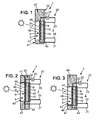
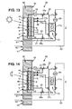
- FIGS. 4A and 4B illustrate a third variant which differs mainly from the variants described above in that the wall element is in the form of a brick 50, the other components remaining identical.
- the brick 50 may constitute an autonomous solar thermal system, shown on the figures 1 and 4A , or a modular solar thermal system, shown on the Figure 4B and wherein several bricks 50, or more panels 40, are connected to each other.
- each brick 50 has opposite upper 51 and lower 52 side surfaces extending between the first 41 and second 42 faces.
- the recovery line 9 the inlet and the outlet of the heat emitter 15 are embedded in the brick 50.
- the outlet of the recovery pipe 9 and the inlet of the heat emitter 15 open on the first connecting surface, upper, made on the upper lateral surface 51 of the brick 50.
- the inlet of the recovery pipe 9 and the outlet of the heat emitter 15 open on the second connecting surface, lower, realized on the lower side surface 52 of the brick 50.
- the solar thermal system 1 then comprises at least a first 50a and a second 50b bricks each provided with the solar thermal collector 5, the heat emitter 15, the insulating layer 45 and the transparent wall 46 as described herein. -above.
- the upper connecting surface of the first brick 50a is placed in contact with the lower connection surface of the second brick 50b so that the exit of the recovery pipe 9 of the first brick 50a is connected to the inlet of the pipe.
- recovery 9 of the second brick 50b, and the input of the heat emitter 15 of the first brick 50a is connected to the output of the heat emitter 15 of the second brick 50b.
- the modular design provides that the second brick 50b overlaps the first brick 50a and a third brick 50c.
- This design is made possible by the juxtaposition, in each of the bricks 50, of two absorbers and two contiguous solar exchangers, two contiguous heat emitters 15 and two parallel diffusion circuits 20.
- Each brick thus has two inputs and two outputs for the coolant on the side of the absorber and the exchanger, and two inputs and two outputs on the side of the heat emitter.
- each brick 50 is not necessarily provided with a drive device 25.
- the drive device 25 can circulate the heat transfer fluid in a hydraulic circuit constituted by the interconnection of several bricks 50. Two models of brick, bucket and hydraulic collector depending on the presence or absence of heat transfer fluid supply opening for other adjacent bricks, can then to be provided.
- the solar thermal collector 5 can also be connected to the heat emitter 15 by the interconnection of several bricks 50.
- a heat emitter 15 is common to several or all the bricks 50 (or panels 40).
- the output of the recovery line 9 of one of the bricks 50, located above the other bricks 50 with which it shares the heat emitter 15 is connected to the input of the transmitter 15 and the inlet of the recovery pipe 9 of one of the bricks 50, located below the other bricks 50 with which it shares the heat emitter 15, is connected to the output of the transmitter of heat 15.
- the solar thermal system 1 according to the first embodiment has many advantages.
- the solar thermal system 1 makes it possible to integrate a solar system into the building so that the walls of the building incorporate structural functions (resistance to mechanical and environmental stresses) and energy (capture, conversion, storage and diffusion of energy).
- the solar thermal system 1 locally constitutes an opaque wall surface capable of resuming mechanical stresses, thus simplifying the architectural integration of the energy functions that the building envelope elements must take up and which were generally designed as grafts. that is, elements with energy functions (insulation, systems) were reported on the envelope.
- the compactness of the solar thermal system 1 which makes it possible to improve its integration with the building envelope offers applications in the construction of new buildings as well as in the renovation of buildings.
- the solar thermal system 1 is integrated into an existing wall in the same way as for the drilling and installation of an opening, such as a window.
- the solar thermal system 1 also offers good adaptability by the appropriate choice of dimensions and autonomous or modular design. It can also be prefabricated.
- the solar thermal system allows to capture and return to the building the contribution of free solar radiation on the envelope, although being opaque. It is thus possible to value the contribution of solar radiation on the opaque parts of the building envelope. This is particularly advantageous compared to earlier constructions in which the contribution of solar radiation on the building, although significantly higher than its needs during a year, was made available only through the openings, which do not typically represent 20% to 60% of the envelope surface so that the opaque walls, ie 40% to 80% of the surface, do not contribute to the use of solar radiation input by the building .
- the solar thermal system 1 provides thermal insulation significantly reducing the heat requirement of the building, which becomes thermally active.
- the solar thermal system integrates an energy storage that overcomes the intermittency of the solar resource and guarantees the comfort of the occupants.
- the simplified structure of the solar thermal system 1 makes it possible to simplify the regulation thereof.
- the figure 5 illustrates an embodiment of the solar thermal collector 5 which may in particular be implemented in the solar thermal system 1 described above.
- the solar thermal collector 5 comprises the absorber and the exchanger in the form of the absorption plate 6 and the recovery pipe 9, it being understood that the recovery pipe 9 can form both the absorber and the exchanger as previously indicated.
- the solar thermal collector 5 also comprises the storage member 10.
- the storage member 10 covers the outer surface of the recovery line 9 leaving the absorption surface 7 uncovered.
- the storage member 10 substantially surrounds the entire outer surface of the metal tube constituting the recovery line 9, with the exception of the outer surface portion secured to the absorption plate 6.
- the solar thermal collector 5 comprises one or more thermal diffusion elements extending in the storage member 10 from the outer surface of the recovery line 9, opposite the absorption surface 7.
- the thermal diffusion elements each comprise a metal fin 11 having a base secured, for example by welding, to the outer surface of the metal tube of the recovery pipe 9.
- the metal fins 11 are immersed in the layer of material of the storage member 10 in which they extend, for example, in a direction substantially perpendicular to the absorption surface 7 over the entire thickness of the storage member 10.
- the metal fins 11 may have a thickness between 0 , 5 mm and 2 mm and a length substantially identical to the thickness of the storage member 10, namely between 2 cm and 7 cm.
- a metal bulb 12 between the metal tube and the base of the metal fin 11 can be realized.
- a metal extension 13 extends perpendicularly to the metal fin 11, at a free end, opposite the base.
- a second metal extension 13 extends perpendicularly to the metal fin 11, between its free end and its base.
- the solar thermal collector 5 described above makes it possible to limit the number of exchangers in the solar thermal system.
- the compactness of the solar thermal system, as well as its integration potential, but also its energy performance, are improved.
- the figure 7 illustrates the steady-state temperature field with circulation of the coolant in the recovery line.
- the solar thermal collector 5 is in a direct use state in which it is placed when sufficient solar radiation reaches the absorption surface 7. This state, the central unit controls the diffusion circuit 20 to circulate the coolant in the recovery line 9.
- the heat exchange between the coolant and the recovery line 9 carrying the absorption surface 7 takes over on the possible heat exchange between the recovery line 9 and the storage member 10 and between the absorption plate 6 and the outside air.
- the heat transfer fluid then carries most of the thermal energy captured by the absorption surface 7.
- the storage member 10 is not or little power and no thermal conduction achieved by the metal fins 11 does not appear.
- the figure 8 is a graph illustrating the distribution of the incident solar flux on the absorption surface 7 between the storage member 10 and the heat transfer fluid, in the direct use state of the solar thermal collector. It can notably be observed that after three hours of operation in the direct use state, approximately 70% of the thermal energy received by the absorption plate 7 is transmitted to the coolant and that about 30% of the thermal energy is stored in the storage member 10. It should be noted that the graph of the figure 8 was obtained with a storage member initially discharged, the temperature of the heat transfer fluid then being initially equal to the temperature of the storage member 10 so that the extracted flow is low. If the storage member 10 has a temperature greater than that of the heat transfer fluid, the ratio between the energy transported by the heat transfer fluid and the energy stored in the storage member 10 will be more favorable.
- the figure 9 illustrates the temperature field after three hours of sunshine with the heat transfer fluid stagnant in the recovery line.
- the solar thermal collector 5 is in a storage state.
- the central unit controls the diffusion circuit 20 to leave the coolant immobile inside the recovery line 9.
- the coolant and the recovery line 9 behave as a homogeneous assembly connected to the plate absorption 6 which transmits the absorbed thermal energy to the storage member 10 via the exchange surface 8 of the absorption plate 6, the recovery pipe 9 and the metal fins 11 as it appears field lines on the figure 8 .
- the figure 10 illustrates the discharge temperature field of the storage member.
- the solar thermal collector 5 is in a destocking state of the solar thermal collector when the solar radiation is insufficient.
- the central unit controls the diffusion circuit 20 to circulate the coolant in the recovery line 9.
- the thermal energy stored in the storage member 10 is then drawn in particular via the metal fins 11, as the show the field lines, and transferred to the coolant and then transported to a use such as the heat emitter 15 in the solar thermal system 1 according to the first embodiment.
- the solar thermal sensor 5 behaves as an open thermal energy switch, when the heat transfer fluid is immobile in the recovery pipe 9, as in the storage state, and closed when the heat transfer fluid circulates in the recovery line 9, as in the direct use and destocking states. When closed, the switch transfers thermal energy to a system that uses this thermal energy. When opened, the switch is used to store thermal energy.
- the solar thermal sensor 5 described above implemented in the solar thermal system 1 according to the first embodiment allows a simple way to automate the regulation of the solar thermal system 1 to heat the living space 2. It is described now a method for heating the living space 2 implementing the solar thermal system 1 according to the first embodiment with the solar thermal sensor 5 described above.
- the central unit After exposing the absorption surface 7 to the solar radiation and measuring the outside temperature outside the living space 2, the inside temperature inside the living space 2, the temperature of the absorption surface 7, the temperature of the storage member 10 and the heat transfer fluid inlet temperature in the recovery line 9, the central unit determines whether there is a need for heating.
- the central unit measures the difference between the indoor temperature and a desired temperature for heating (comfort temperature) which controls the operation of the solar thermal system according to the heating requirements.
- This desired temperature can be set either by a room thermostat or determined from the outside temperature and a predefined water law stored in the memory of the central unit.
- the central unit controls the diffusion circuit to put the solar thermal collector 5 in the state storage, the heat transfer fluid being immobile in the recovery line 9 and, if a solar input exists, the thermal energy being stored in the storage member 10.
- the central unit determines whether or not the absorption surface 7 is exposed to solar radiation.
- the central unit determines whether thermal energy can be taken by the heat transfer fluid on the absorption plate 6.
- Thermal energy can be taken by the coolant on the absorption plate 6 when the inlet temperature of the heat transfer fluid is lower than the temperature of the absorption surface 7. If this is the case, then the central unit controls the diffusion circuit 20 to put the solar thermal collector 5 in the state of direct use and to circulate the coolant in the recovery line 9 and the heat emitter 15. The thermal energy absorbed by the absorption surface 7 is thus transferred to the heat emitter 15.
- the heat transfer fluid inlet temperature is higher than the temperature of the absorption surface 7, the heat transfer fluid can not take heat energy from the absorption plate 6 and the central unit measures the heat transfer fluid. the difference between the inlet temperature of the coolant and the temperature of the storage member 10 to determine whether heat energy can be taken from the storage member 10.
- the storage member stores thermal energy that can be taken by placing the solar thermal sensor 5 in the destocking state.
- the central unit controls the diffusion circuit 20 to circulate the heat transfer fluid in the recovery line 9 and the heat emitter 15 so as to transfer to the heat emitter 15 the thermal energy stored in the storage 10.
- the central unit controls the diffusion circuit 20 to put the solar thermal collector in the storage state and leave the coolant immobile inside the recovery line 9 in order to store the thermal energy absorbed by the heat sink plate. absorption 6.
- the central unit measures the difference between the inlet temperature coolant and the temperature of the storage member 10.
- the central unit controls the diffusion circuit 20 to circulate the coolant in the recovery line 9 and the heat emitter 15 so as to transfer to the heat emitter 15 the thermal energy stored in the storage member 10.
- the central unit controls the diffusion circuit 20 to leave the coolant immobile inside the recovery line 9.
- the description of the solar thermal collector 5 of Figures 5 and 6 was made in connection with the solar thermal system 1 of heating.
- the solar thermal sensor 5 is however not limited to such an application and can be used in other applications in which it is not coupled to a heat emitter or it is not integrated into a wall element.
- the solar thermal collector 5 may, for example, be used in a hot water installation.
- the solar thermal collector 5 can also serve as an exchanger for the heat pump heat source which comprises two exchangers forming one an evaporator, and the other a condenser, and a refrigerant circulating between the evaporator and the condenser.
- the solar thermal collector 5 can then constitute the evaporator of the heat pump and the coolant is the refrigerant (direct expansion operation). However, it can be provided to introduce an exchanger between the solar thermal collector 5 and the evaporator of the heat pump.
- the figure 11 represents a solar thermal system 60 for heating the living space 2 according to a second embodiment.
- the solar thermal system 60 implements components similar to those of the first embodiment described above in connection with the figures.
- the analogous components namely the solar thermal collector 5, the heat emitter 15, the diffusion circuit 20, the panel 40, the transparent wall 46 and the insulation layer 45, reference will be made to the description made previously.
- the solar thermal system 60 differs from the first embodiment mainly in that it comprises a heat pump 70 coupled to the solar thermal collector 5 and to the heat emitter 15, an internal air circuit and an outdoor air circuit.
- the outside air circuit comprises an air inlet mouth 61 and an air outlet mouth 62 formed in the panel 40, an air circulation duct 63 interconnecting the inlet mouths 61 and outlet 62 of air, and a fan 64 arranged to circulate the outside air in the air duct 63 at a rate set by the characteristics of the heat pump 70.
- the air inlet 61 may have a square section of 10 cm or 25 cm depending on the air flow required to meet the heating requirement of the living space 2.
- the fan 64 may impose an air flow of between 200 m 3 / h and 350 m 3 / h when the heat pump 70 is running.
- the interior air circuit comprises an air intake valve 65 mounted on a portion of the air duct 63 comprising the fan 64, and an air rejection valve 66 mounted on the portion of the duct. air circulation 63.
- the air intake valve 65 is provided with an indoor air intake opening 67 and the air rejection valve 66 is provided with a hot air blower 68.
- the heat pump 70 comprises two exchangers 71 forming one an evaporator, and the other a condenser, and a refrigerant flowing between the exchangers.
- the heat pump 70 is said to be reversible insofar as each of the exchangers 71 can in turn become the evaporator and the condenser.
- the heat pump 70 comprises a first heat exchanger 71a and a second heat exchanger 71b which is in contact with the portion of the air flow duct 63 between the air intake and air rejection valves 65.
- another drive device 70 may be integrated with the heat pump to allow circulating coolant in the diffusion circuit 20 when the outlet line 22 of the recovery line is disconnected from the coolant circulation circuit. It is also recalled here that thermosiphon operation of the solar thermal system is possible.
- the diffusion circuit 20 comprises a bypass line 27 passing through the first heat exchanger 71a of the heat pump 70.
- the first, second and third three-way valves are controlled by the central unit.
- non-return valves 28 are provided in the heat emitter input pipe 23 and in the second portion 27b of the bypass pipe.
- the temperature of the heat transfer fluid at the outlet of the recovery line 9 is measured, and a target temperature for the heat transfer fluid is determined.
- the set temperature corresponds to the flow temperature of the coolant for heating by the heat emitter.
- the central unit can be adapted to calculate the set temperature, that is to say the flow temperature of the heat transfer fluid necessary for the heat emitter to provide sufficient heat, from the temperature outdoor, desired temperature within living space 2 and a predefined water law stored in the memory.
- the water law set during the commissioning of the solar thermal system 60 in particular according to the losses of the living space 2 and the nominal power and the dimensions of the heat emitter 15, indeed relates the temperature starting of the coolant necessary for the input of the heat emitter 15 to satisfy the heating requirement, and the outside temperature.
- the solar thermal collector 5 provides sufficient thermal energy and a sufficient water temperature to cover the heating needs directly by the heat emitter 15. This is detected by the central unit when the temperature of the coolant at the outlet of the recovery line 9 is greater than the set temperature. The central unit then puts the solar thermal system 60 into a solar heating operation in which the thermal energy is absorbed by the absorption surface 7 of the solar thermal collector 5 and the heat emitter 15 is transferred to the heat emitter thermal absorbed.
- the solar thermal system 1 is reduced to the solar thermal system 1 according to the first embodiment by controlling, by means of the central unit, the first 26a and second 26b three-way valves to connect the outlet pipe 22 of pipe recovering to the heat emitter input conduit 23, and the heat emitter output conduit 24 to the recovery line inlet conduit 21.
- the drive device 25 controlled by the central unit circulates the heat transfer fluid in a closed circuit between the recovery line 9, the outlet line 22 of the recovery line, the input pipe 23 of the heat emitter, the heat emitter 15, the heat emitter output pipe 24, the recovery pipe inlet pipe 21.
- the temperature of the heat transfer fluid leaving the recovery pipe 9 does not allow the distribution of heat in the living space 2.
- a supplement provided by the heat pump 70 is then necessary.
- Such a situation can be detected by the central unit when the temperature of the coolant at the outlet of the recovery line 9 is located in a first predetermined range of lower temperatures and close to the set temperature.
- This first temperature range can be stored in the memory of the central unit.
- the first temperature range comprises temperatures less than 7 ° C relative to the set temperature, in particular less than 3 ° C relative to the set temperature.
- the central unit puts the solar thermal system 60 into a supplementary thermodynamic heating operation in which the thermal energy is absorbed by the absorption surface 7, a thermal energy is taken from the air outside by the heat pump 70 and transferred to the heat emitter 15 the thermal energy absorbed and the thermal energy taken.
- the second exchanger 71 b of the heat pump is the evaporator which will take heat energy to the outside air as a cold source.
- the outside air enters through the air inlet 61, is circulated in the air duct 63 by means of the fan 64 and is discharged through the air blower 62 after the refrigerant heat pump 70 took the heat energy from it in the evaporator.
- the first heat exchanger 71a of the heat pump constitutes the condenser.
- the central unit controls the first three-way valve 26a to connect the recovery line outlet line 22 to the first portion 27a of the bypass line.
- the second three-way valve 26b is, in turn, controlled to connect the output line 24 of the heat emitter to the inlet line 21 of the recovery line.
- the third three-way valve 26c it is controlled to connect the first 27a and second 27b portions of the branch line.
- the central unit then controls the drive device 25 to circulate the coolant in the recovery line 9 and then in the outlet line 22 of the recovery line and in the first portion 27a of the bypass line where the heat transfer fluid as hot source preheated by the solar thermal collector 5 takes the heat energy from the refrigerant of the heat pump 70 during its passage in the condenser formed by the first exchanger 71 a.
- the heat transfer fluid is then circulated in the second portion 27b of the bypass pipe and then in the heat emitter 15, the heat emitter output pipe 24, the recovery pipe inlet pipe 21 and, at new in the recovery line 9.
- thermodynamic system constituted by the heat pump 70 is, in the embodiment described, used in addition to the solar thermal collector 5, which performs a preheating of the hot source.
- the absence of solar radiation can be detected by the central unit when the temperature of the heat transfer fluid leaving the recovery pipe 9 is located in a second predetermined range of temperatures below and away from the temperature deposit.
- This second temperature range can be stored in the memory of the central unit.
- the second temperature range includes temperatures below the temperatures of the first temperature range.
- thermodynamic heating in which it is determined whether there is thermal energy stored in the storage member 10.
- the thermal energy in the storage member 10 is exhausted or insufficient, in particular by relative to the heat energy available in the outside air, the thermal energy is taken from the outside air and the heat energy taken off is transferred to the heat emitter.
- the first 71a and second 71b exchangers of the heat pump 70 respectively constitute the condenser and the evaporator.
- the central unit controls the first three-way valve 26a to connect the first portion 27a of the branch line to the heat emitter input line 23.
- the second three-way valve 26b is controlled to connect the third portion 27c of the bypass line to the heat emitter output line 24.
- the third three-way valve 26c it is controlled to connect the first 27a and third 27c portions of the branch line.
- the heat transfer fluid in the first portion 27a of the bypass pipe is then circulated, for example by means of the heat pump driving device 70, where the heat transfer fluid as a hot source takes the heat energy from the refrigerant. of the heat pump 70 during its passage in the condenser formed by the first exchanger 71 a.
- the heat transfer fluid is then circulated in the heat emitter inlet pipe 23, in the heat emitter 15, in the heat emitter outlet pipe 24, in the third portion 27c of the bypass pipe. then again in the first portion 27a of the bypass pipe.
- the storage member 10 has a temperature greater than the temperature of the heat transfer fluid at the outlet of the recovery line 9 and, if the temperature of the storage member 10 is greater than or equal to the external temperature, it is possible to take the thermal energy stored in the storage member 10 and transfer it to the indoor air.
- the first heat exchanger 71a of the heat pump constitutes the evaporator and the second heat exchanger 71b of the heat pump constitutes the condenser.
- the air intake and air rejection valves 65 isolate the air duct portion 63 located between them from the remainder of the circulation duct 63 and the fan 64 creates an interior air flow in the circulation duct. 63 between the indoor air intake port 67, through which the interior air is drawn into the circulation duct 63, and the hot air blower outlet 68, through which the interior air as a hot source heated during its passage in the condenser formed by the second exchanger 71b is expelled.
- the air flow rate imposed by the fan 64 is then preferably of the order of 0.05 kg / s to 0.1 kg / s.
- the central unit controls the first three-way valve 26a to connect the first portion 27a of the bypass line to the recovery line outlet line 22.
- the second three-way valve 26b is controlled to connect the third portion 27c of the bypass line to the inlet line 21 of the recovery line.
- the third three-way valve 26c is controlled to connect the first 27a and third 27c portions of the bypass line.
- the central unit controls the circulation device 25 to circulate the coolant in the recovery line 9 where it draws the thermal energy stored in the storage member 10.
- the heat transfer fluid then flows in the outlet pipe 22 of recovery line and then the first portion 27a of the bypass pipe where the refrigerant takes the thermal energy of the heat transfer fluid during its passage in the evaporator formed by the first exchanger 71 a.
- the coolant then returns to the recovery line 9 through the third portion 27c of the bypass line and the inlet line 21 of the recovery line.
- the storage member 10 at which heat energy is removed forms the cold source of the thermodynamic system, thus ensuring an efficient and integral exploitation of the solar radiation converted into thermal energy.
- the solar thermal collector 5 can be successively used as heat exchanger for the heat source of the heat pump 70 and then as exchanger for the cold source of the heat pump 70.
- this arrangement makes it possible to improve the coefficient of performance of the heat pump when it has to meet the need for heating.
- the heat pump 70 draws particular benefit from the fact that it works with a cold source whose temperature is frequently higher than outside air, especially due to solar radiation and storage.
- bypass line 27 is limited to the first portion 27a described above and which is then connected, on the one hand, to the first three-way valve 26a and, secondly, to the second three-way valve 26b.
- This variant has the same operating modes as those described above with the exception of operation in auxiliary thermodynamic heating.
- the solar thermal system 60 has been described in relation to a wall element and a storage member. These elements could, however, be optional components.
- the solar thermal collector 5 could be devoid of storage member 10 so that the solar thermal system 60 realizes the solar heating mode of operation, the embodiment of thermodynamic heating auxiliary as well as the mode of operation in thermodynamic heating corresponding to the case where the stored thermal energy is exhausted.
Description
L'invention se rapporte à un système solaire thermique pour chauffer un espace habitable.The invention relates to a solar thermal system for heating a living space.
En particulier, l'invention se rapporte à un système solaire thermique pour chauffer un espace habitable, comprenant :
- un élément de paroi destiné à être incorporé dans une paroi d'un bâtiment délimitant l'espace habitable, l'élément de paroi présentant des première et deuxième faces opposées et comportant intérieurement un logement ouvert sur la première face, la première face étant destinée à être exposée au rayonnement solaire,
- au moins un capteur solaire thermique comprenant une conduite de récupération thermiquement conductrice, adaptée pour recevoir un fluide caloporteur et portant extérieurement une surface d'absorption du rayonnement solaire, le capteur solaire thermique étant placé à l'intérieur du logement avec la surface d'absorption sur la première face de l'élément de paroi, le capteur solaire thermique comprenant en outre un organe de stockage d'énergie thermique placé dans le logement de l'élément de paroi en contact avec la conduite de récupération à l'opposé de la surface d'absorption,
- au moins un émetteur de chaleur adapté pour recevoir le fluide caloporteur et connecté (directement ou indirectement) au capteur solaire thermique, l'émetteur de chaleur s'étendant sur la deuxième face de l'élément de paroi.
- a wall element intended to be incorporated in a wall of a building delimiting the living space, the wall element having opposite first and second faces and internally having an open housing on the first face, the first face being intended for be exposed to solar radiation,
- at least one solar thermal sensor comprising a thermally conductive recovery pipe, adapted to receive a heat transfer fluid and externally carrying a solar radiation absorption surface, the solar thermal sensor being placed inside the housing with the absorption surface on the first face of the wall element, the solar thermal sensor further comprising a thermal energy storage member placed in the housing of the wall element in contact with the recovery line opposite the surface absorption,
- at least one heat emitter adapted to receive the heat transfer fluid and connected (directly or indirectly) to the solar thermal collector, the heat emitter extending on the second face of the wall element.
On connaît, notamment du document
Or le rayonnement solaire n'est généralement pas en phase avec les besoins en chauffage du bâtiment de sorte qu'il est nécessaire d'avoir recours à des systèmes de chauffage d'appoint qui fonctionnent en l'absence de rayonnement solaire ou lorsque le rayonnement solaire est insuffisant. En outre, les systèmes solaires thermiques connus n'offrent pas une capacité d'intégration à la paroi du bâtiment satisfaisante.However, the solar radiation is generally not in line with the heating requirements of the building so that it is necessary to use auxiliary heating systems that operate in the absence of solar radiation or when the radiation solar is insufficient. In addition, the known solar thermal systems do not offer a satisfactory integration capacity to the building wall.
L'invention vise à pallier les problèmes évoqués ci-dessus.The invention aims to overcome the problems mentioned above.
A cet effet, l'invention propose un système solaire thermique du type précité dans lequel la conduite de récupération comporte une entrée et une sortie noyées dans l'élément de paroi, la sortie de la conduite de récupération débouchant sur une première surface de connexion de l'élément de paroi, et l'entrée de la conduite de récupération débouchant sur une deuxième surface de connexion de l'élément de paroi.For this purpose, the invention proposes a solar thermal system of the aforementioned type in which the recovery line comprises an inlet and an outlet embedded in the wall element, the outlet of the recovery pipe leading to a first connecting surface of the wall element, and the inlet of the recovery pipe opening to a second connecting surface of the wall element.
Ainsi, le système solaire thermique selon l'invention intègre en outre la fonction énergétique de stockage d'énergie thermique qui permet de restituer l'énergie thermique issue du rayonnement solaire, y compris en l'absence de rayonnement solaire ou lorsque le rayonnement solaire est insuffisant. Il est ainsi possible de pallier l'intermittence du rayonnement solaire et d'améliorer l'adéquation entre l'apport en rayonnement solaire et les besoins en chauffage.Thus, the solar thermal system according to the invention also incorporates the energy storage function of thermal energy that allows to restore the thermal energy from solar radiation, including in the absence of solar radiation or when the solar radiation is insufficient. It is thus possible to mitigate the intermittency of the solar radiation and to improve the adequacy between the contribution of solar radiation and the heating needs.
Par ailleurs, l'agencement intégré de l'organe de stockage dans l'élément de paroi présente l'avantage d'une conception compacte du système solaire thermique combinant les fonctions structurelles et l'ensemble des fonctions énergétiques (captation, conversion, stockage et diffusion). Chaque élément de paroi peut, en outre, constituer un module qui peut être utilisé de manière autonome ou en combinaison avec d'autres modules analogues. L'adaptabilité, la capacité d'intégration à la paroi du bâtiment et la modularité du système solaire thermique s'en trouvent améliorées.Furthermore, the integrated arrangement of the storage member in the wall element has the advantage of a compact design of the solar thermal system combining the structural functions and all the energy functions (capture, conversion, storage and diffusion). Each wall element may, in addition, constitute a module that can be used independently or in combination with other similar modules. The adaptability, the capacity of integration to the wall of the building and the modularity of the solar thermal system are improved.
Dans un mode de réalisation, le logement peut être ouvert sur la deuxième face de l'élément de paroi, l'émetteur de chaleur étant placé en regard et à distance de l'organe de stockage, le système solaire thermique comprenant en outre une couche d'isolation thermique interposée entre l'organe de stockage et l'émetteur de chaleur.In one embodiment, the housing can be open on the second face of the wall element, the heat emitter being placed opposite and at a distance from the storage member, the solar thermal system further comprising a layer thermal insulation interposed between the storage member and the heat emitter.
En particulier, les première et deuxième surfaces de connexion peuvent être opposées l'une par rapport à l'autre et s'étendre entre les première et deuxième faces de l'élément de paroi.In particular, the first and second connecting surfaces may be opposed to one another and extend between the first and second faces of the wall member.
Le système solaire thermique peut alors comprendre au moins un premier et un deuxième éléments de paroi, au moins un premier et un deuxième capteurs solaires thermiques placés respectivement dans les logements des premier et deuxième éléments de paroi, et au moins un émetteur de chaleur s'étendant sur au moins l'une des deuxièmes faces des premier et deuxième éléments de paroi, la première surface de connexion du premier élément de paroi étant en contact avec la deuxième surface de connexion du deuxième élément de paroi, la sortie de la conduite de récupération du premier capteur solaire thermique étant connectée à l'entrée de la conduite de récupération du deuxième capteur solaire thermique.The solar thermal system may then comprise at least a first and a second wall element, at least a first and a second solar thermal collector respectively placed in the housing of the first and second wall elements, and at least one heat emitter. extending on at least one of the second faces of the first and second wall members, the first connecting surface of the first wall member being in contact with the second connecting surface of the second wall member, the exit of the recovery pipe the first solar thermal collector being connected to the inlet of the recovery line of the second solar thermal collector.
Par ailleurs, l'émetteur de chaleur peut comporter une entrée et une sortie noyées dans l'élément de paroi, l'entrée de l'émetteur de chaleur débouchant sur la première surface de connexion de l'élément de paroi, et la sortie de l'émetteur de chaleur débouchant sur la deuxième surface de connexion de l'élément de paroi.Furthermore, the heat emitter may comprise an inlet and an outlet embedded in the wall element, the inlet of the heat emitter opening onto the first connection surface of the wall element, and the exit of the heat emitter opening on the second connecting surface of the wall element.
L'organe de stockage peut être adapté pour réaliser un stockage thermique sensible, auquel cas l'organe de stockage peut présenter une chaleur spécifique comprise entre 800 J/Kg.K et 1500 J/Kg.K, ou être adapté pour réaliser un stockage thermique latent, auquel cas l'organe de stockage peut être constitué d'un matériau à changement de phase présentant une température de fusion comprise entre 15 °C et 45°C et une chaleur latente de fusion comprise entre50 kJ/kg et 250 kJ/kg.The storage member may be adapted to perform sensible thermal storage, in which case the storage member may have a specific heat between 800 J / Kg.K and 1500 J / Kg.K, or be adapted to perform latent thermal storage, in which case the storage member may consist of a phase change material having a melting temperature included between 15 ° C and 45 ° C and a latent heat of fusion of between 50 kJ / kg and 250 kJ / kg.
De manière complémentaire ou indépendante des dispositions précédentes, l'élément de paroi peut présenter une surface intérieure délimitant le logement, la surface intérieure comprenant au moins localement une surface réfléchissante agencée pour orienter le rayonnement solaire qui atteint ladite surface réfléchissante vers la surface d'absorption.Complementarily or independently of the preceding arrangements, the wall element may have an interior surface delimiting the housing, the inner surface comprising at least locally a reflecting surface arranged to orient the solar radiation which reaches said reflecting surface towards the absorption surface. .
On peut, en outre, prévoir que le système solaire thermique comprenne une paroi transparente au rayonnement solaire et isolante thermiquement placée sur la face avant de l'élément de paroi, en regard de la surface d'absorption du capteur solaire thermique.It can further be provided that the solar thermal system comprises a thermally insulated solar radiation-transparent wall placed on the front face of the wall element, facing the absorption surface of the solar thermal collector.
Par ailleurs, l'élément de paroi peut comprendre une couche d'isolation thermique sur la première face, autour du logement.Furthermore, the wall element may comprise a thermal insulation layer on the first face, around the housing.
Dans un mode de réalisation pouvant mettre en oeuvre une ou plusieurs des dispositions précédentes, la conduite de récupération et l'émetteur de chaleur peuvent comporter chacun une entrée et une sortie pour le fluide caloporteur, le système solaire thermique pouvant comprendre en outre :
- un fluide caloporteur,
- une pompe à chaleur qui comporte deux échangeurs formant l'un un évaporateur, et l'autre un condenseur,
- un circuit d'air extérieur,
- un circuit d'air intérieur,
- un circuit de diffusion adapté pour recevoir le fluide caloporteur et commandé pour :
- dans un fonctionnement en chauffage solaire, lorsque le fluide caloporteur en sortie de la conduite de récupération présente une température supérieure à une température de consigne pour le fluide caloporteur (c'est-à-dire une température de départ du fluide caloporteur pour le chauffage par l'émetteur de chaleur, déterminée notamment par une loi d'eau), connecter la sortie de la conduite de récupération à l'entrée de l'émetteur de chaleur, connecter la sortie de l'émetteur de chaleur à l'entrée de la conduite de récupération, et faire circuler le fluide caloporteur de sorte à transférer à l'émetteur de chaleur une énergie thermique absorbée par la surface d'absorption,
- dans un fonctionnement en chauffage thermodynamique, lorsque le fluide caloporteur en sortie de la conduite de récupération présente une température située dans une plage prédéfinie de températures inférieures à la température de consigne pour le fluide caloporteur,
sinon, si l'organe de stockage présente une température inférieure à la température du fluide caloporteur en sortie de la conduite de récupération ou si la température de l'organe de stockage est inférieure à la température extérieure, connecter l'évaporateur de la pompe à chaleur au circuit d'air extérieur, et connecter la sortie de l'émetteur de chaleur à l'entrée de l'émetteur de chaleur au travers du condenseur de la pompe à chaleur, de sorte à transférer à l'émetteur de chaleur l'énergie thermique prélevée dans l'air extérieur.In one embodiment that can implement one or more of the preceding provisions, the recovery line and the heat emitter may each have an inlet and an outlet for the heat transfer fluid, the solar thermal system may further comprise:
- a heat transfer fluid,
- a heat pump which comprises two exchangers forming one an evaporator, and the other a condenser,
- an outside air circuit,
- an indoor air circuit,
- a diffusion circuit adapted to receive the coolant and controlled for:
- in a solar heating operation, when the coolant at the outlet of the recovery pipe has a temperature higher than a set temperature for the coolant (that is to say a starting temperature of the coolant for heating by the heat emitter, determined in particular by a water law), connect the output of the recovery line to the input of the heat emitter, connect the output of the heat emitter to the input of the recovery line, and circulating the heat transfer fluid so as to transfer to the heat emitter a thermal energy absorbed by the absorption surface,
- in a thermodynamic heating operation, when the heat transfer fluid leaving the recovery pipe has a temperature within a predefined range of temperatures below the set temperature for the coolant,
otherwise, if the storage member has a temperature lower than the temperature of the coolant at the outlet of the recovery line or if the temperature of the storage member is lower than the outside temperature, connect the evaporator of the pump to heat the external air circuit, and connect the output of the heat emitter to the input of the heat emitter through the condenser of the heat pump, so as to transfer to the heat emitter the thermal energy taken from the outside air.
Dans le mode de réalisation qui vient d'être décrit, le circuit de diffusion peut en outre être commandé pour, dans un fonctionnement en chauffage thermodynamique d'appoint, lorsque le fluide caloporteur en sortie de la conduite de récupération présente une température située dans une plage prédéfinie de températures inférieures et proches de la température de consigne pour le fluide caloporteur, connecter l'évaporateur de la pompe à chaleur au circuit d'air extérieur, connecter la sortie de la conduite de récupération à l'entrée de l'émetteur de chaleur au travers du condenseur de la pompe à chaleur, connecter la sortie de l'émetteur de chaleur à l'entrée de la conduite de récupération, et faire circuler le fluide caloporteur de sorte à transférer à l'émetteur de chaleur l'énergie thermique absorbée par la surface d'absorption et l'énergie thermique prélevée dans l'air extérieur.In the embodiment which has just been described, the diffusion circuit can be further controlled for, in a thermodynamic supplemental heating operation, when the coolant at the outlet of the recovery pipe has a temperature in a predefined range of temperatures below and close to the set temperature for the coolant, connect the evaporator of the heat pump to the outside air circuit, connect the outlet of the recovery line to the input of the transmitter of the heat through the condenser of the heat pump, connect the output of the heat emitter to the inlet of the recovery pipe, and circulate the heat transfer fluid so as to transfer heat energy to the heat emitter absorbed by the absorption surface and the thermal energy taken from the outside air.
D'autres objets et avantages de l'invention apparaîtront à la lecture de la description qui suit, faite en référence aux dessins annexés dans lesquels :
- la
figure 1 est une représentation schématique en coupe d'un système solaire thermique selon un premier mode de réalisation, illustrant un élément de paroi sous la forme d'un panneau, un capteur solaire thermique placé dans un logement de l'élément de paroi, et un émetteur de chaleur monté sur l'élément de paroi, - la
figure 2 est une représentation schématique en coupe du système solaire thermique selon une première variante du premier mode de réalisation de lafigure 1 , dans laquelle l'élément de paroi est pourvu d'une couche d'isolation thermique sur une face exposée au rayonnement solaire, - la
figure 3 est une représentation schématique en coupe du système solaire thermique selon une deuxième variante du premier mode de réalisation de lafigure 1 , dans laquelle le logement de l'élément de paroi est délimité par une surface intérieure dont une partie est réfléchissante, - les
figures 4A et 4B sont des représentations en perspective du système solaire thermique selon une troisième variante du premier mode de réalisation de lafigure 1 , dans laquelle l'élément de paroi se présente sous la forme d'une brique, lesfigures 4A et 4B illustrant respectivement le système solaire thermique comprenant une brique et un assemblage de briques, - la
figure 5 est une représentation schématique en coupe d'un mode de réalisation du capteur solaire thermique du système solaire thermique de lafigure 1 , - les
figures 6A, 6B et 6C sont des représentations agrandies du détail référencé VI sur lafigure 5 , - la
figure 7 est une représentation du champ de température en régime établi avec une circulation de fluide caloporteur dans le capteur solaire thermique de lafigure 5 , - la
figure 8 est un graphe illustrant la répartition du flux solaire incident sur le capteur solaire thermique de lafigure 5 entre un organe de stockage d'énergie thermique et le fluide caloporteur, - la
figure 9 est une représentation du champ de température après trois heures d'ensoleillement avec le fluide caloporteur stagnant dans le capteur solaire thermique de lafigure 5 , - la
figure 10 est une représentation du champ de température en décharge de l'organe de stockage du capteur de lafigure 5 , - la
figure 11 est une représentation schématique en coupe d'un système solaire thermique selon un deuxième mode de réalisation, - les
figures 12 ,13 ,14 et15 sont des représentations de différents modes de fonctionnement du système solaire thermique de lafigure 11 , - la
figure 16 est une représentation schématique en coupe du système solaire thermique selon une variante du deuxième mode de réalisation de lafigure 11 .
- the
figure 1 is a schematic sectional representation of a solar thermal system according to a first embodiment, illustrating a wall element in the form of a panel, a solar thermal collector placed in a housing of the wall element, and a transmitter of heat mounted on the wall element, - the
figure 2 is a schematic representation in section of the solar thermal system according to a first variant of the first embodiment of thefigure 1 in which the wall element is provided with a thermal insulation layer on a face exposed to solar radiation, - the
figure 3 is a schematic sectional representation of the solar thermal system according to a second variant of the first embodiment of thefigure 1 in which the housing of the wall element is delimited by an interior surface of which a part is reflective, - the
Figures 4A and 4B are perspective representations of the solar thermal system according to a third variant of the first embodiment of thefigure 1 , in which the wall element is in the form of a brick, theFigures 4A and 4B illustrating respectively the solar thermal system comprising a brick and a brick assembly, - the
figure 5 is a schematic representation in section of an embodiment of the solar thermal collector of the solar thermal system of thefigure 1 , - the
FIGS. 6A, 6B and 6C are enlarged representations of detail referenced VI on thefigure 5 , - the
figure 7 is a representation of the steady-state temperature field with a coolant circulation in the thermal solar collector of thefigure 5 , - the
figure 8 is a graph illustrating the distribution of incident solar flux on the solar thermal collector of thefigure 5 between a thermal energy storage member and the heat transfer fluid, - the
figure 9 is a representation of the temperature field after three hours of sunshine with the heat transfer fluid stagnant in the solar thermal collector of thefigure 5 , - the
figure 10 is a representation of the temperature field in discharge of the storage member of the sensor of thefigure 5 , - the
figure 11 is a schematic representation in section of a solar thermal system according to a second embodiment, - the
figures 12 ,13 ,14 and15 are representations of different modes of operation of the solar thermal system of thefigure 11 , - the
figure 16 is a schematic sectional representation of the solar thermal system according to a variant of the second embodiment of thefigure 11 .
Sur les figures, les mêmes références désignent des éléments identiques ou analogues.In the figures, the same references designate identical or similar elements.
La
Le système solaire thermique 1 comprend un capteur solaire thermique 5 dont la fonction est de convertir le rayonnement solaire en énergie thermique et de rendre disponible cette énergie thermique, directement ou indirectement comme il apparaîtra dans la suite de la description, à un émetteur de chaleur 15 dont la fonction est de dissiper l'énergie thermique sous forme de chaleur.The solar
En particulier, afin de convertir le rayonnement solaire en énergie thermique, le capteur solaire thermique 5 comprend un absorbeur sous la forme d'une plaque d'absorption 6, par exemple généralement plane, en métal tel que du cuivre, qui présente une surface d'absorption 7 destinée à être exposée au rayonnement solaire et une surface d'échange 8 opposée à la surface d'absorption 7. La surface d'absorption 7 permet l'absorption du rayonnement solaire visible et peut, pour ce faire, être recouverte d'une couche appropriée, notamment sélective, c'est-à-dire absorbante dans le rayonnement visible et peu émissive dans le rayonnement infrarouge, comme des peintures noires, contenant éventuellement des particules de carbone, ou comme des dépôts surfaciques d'oxyde de chrome ou d'oxyde de titane.In particular, in order to convert solar radiation into thermal energy, the solar
Afin de pouvoir rendre l'énergie thermique disponible et notamment la transporter vers l'émetteur de chaleur 15, le capteur solaire thermique 5 comprend également un échangeur sous la forme d'une conduite de récupération 9 thermiquement conductrice recevant un fluide caloporteur, par exemple de l'eau mélangée à un adjuvant pour prévenir le gel, tel que du glycol dans une proportion de 15 % à 40 %. La conduite de récupération 9 comporte une entrée et une sortie pour le fluide caloporteur et présente une surface extérieure en contact avec la surface d'échange 8 de la plaque d'absorption 6. La conduite de récupération 9 est répartie sensiblement sur toute la surface d'échange 8. En particulier, la conduite de récupération 9 peut comprendre un tube métallique soudé à la surface d'échange de la plaque d'absorption 6. Le tube métallique peut présenter, par exemple, des portions droites de section circulaire, adjacentes et parallèles entre elles, et des portions coudées de section circulaire reliant deux portions droites adjacentes. En variante, la conduite de récupération 9 peut comprendre un tube réalisé en tout autre matériau adapté pour la conduction de chaleur et solidarisé à la plaque d'absorption 6 par tout moyen approprié.In order to make the thermal energy available and in particular to transport it to the
La description du capteur solaire thermique 5 a été faite en relation avec une conduite de récupération 9 qui porte extérieurement la surface d'absorption 7 de manière indirecte, c'est-à-dire par l'intermédiaire d'une plaque d'absorption 6 avec laquelle la conduite de récupération 9 est en contact direct. En variante, notamment dans le cas où la conduite de récupération 9 présente une section polygonale, par exemple carrée ou rectangulaire, on pourrait prévoir que la conduite de récupération 9 elle-même porte extérieurement la surface d'absorption 7 de manière directe, c'est-à-dire qu'une partie de la surface extérieure de la conduite de récupération 9 forme la surface d'absorption 7. Dans cette variante, la conduite de récupération 9 forme à la fois l'absorbeur et l'échangeur.The description of the solar
Les dimensions de l'absorbeur et de l'échangeur sont adaptées en fonction du besoin de chauffage de l'espace habitable 2 à chauffer et en fonction de l'apport en rayonnement solaire. On peut, par exemple, prévoir que ces dimensions soient telles que le capteur solaire thermique 5 a une aire comprise de préférence entre 0,5 m2 et 4 m2. Par ailleurs, la plaque d'absorption 6 peut présenter une épaisseur comprise entre 1 mm et 5 mm et la conduite de récupération 9 peut comporter un tube métallique dont les sections droites sont espacées d'un entraxe compris entre 6 cm et 15 cm et la section présente un diamètre intérieur de 8 mm et un diamètre extérieur de 9 mm, ou un diamètre intérieur de 10 mm et un diamètre extérieur de 11 mm, ou un diamètre intérieur de 12 mm et un diamètre extérieur de 13 mm, ou un diamètre intérieur de 12 mm et un diamètre extérieur de 14 mm.The dimensions of the absorber and the exchanger are adapted according to the heating need of the
Par ailleurs, comme indiqué précédemment, le capteur solaire thermique 5 peut rendre disponible l'énergie thermique directement, en la transmettant directement à l'émetteur de chaleur 15, ou indirectement, en la transmettant à l'émetteur de chaleur 15 après l'avoir stockée.Furthermore, as indicated above, the solar
Dans le mode de réalisation illustré, le capteur solaire thermique comprend alors un organe de stockage 10 d'énergie thermique en contact avec la surface extérieure de la conduite de récupération 9 à l'opposé de la surface d'absorption 7.In the illustrated embodiment, the solar thermal collector then comprises a thermal
Selon les applications, l'organe de stockage peut être formé par une couche de matériau à forte capacité, adapté pour réaliser un stockage thermique sensible. L'organe de stockage 10 présente alors une chaleur spécifique comprise entre 800 J/Kg.K et 1500 J/Kg.K. Des exemples non limitatifs de matériaux pouvant réaliser ce type de stockage comprennent du béton ou de la brique.According to the applications, the storage member may be formed by a layer of high capacity material adapted to perform sensible thermal storage. The
En variante, l'organe de stockage 10 peut être une couche de matériau à changement de phase adapté pour réaliser un stockage thermique latent. L'organe de stockage 10 peut alors présenter une température de fusion comprise entre 15°C et 45°C, de préférence entre 25°C et 45°C, et une chaleur latente de fusion comprise entre 50 kJ/kg et 250 kJ/kg. Les matériaux à changement de phase présente une conductivité thermique de préférence entre 0,5 W/m.K et 1,5 W/m.K. Des exemples non limitatifs de matériaux pouvant réaliser ce type de stockage comprennent des paraffines.Alternatively, the
L'organe de stockage 10 dont les dimensions sont identiques à celles de l'absorbeur et de l'échangeur présente une épaisseur qui est fonction du besoin en chauffage de l'espace habitable 2 à chauffer et fonction de l'autonomie souhaitée pour le capteur solaire thermique 5. Par exemple, l'organe de stockage 10 peut présenter une épaisseur comprise entre 2 cm et 7 cm.The
L'émetteur de chaleur 15 comporte une entrée et une sortie pour le fluide caloporteur et est adapté pour recevoir le fluide caloporteur. L'émetteur de chaleur 15 peut ainsi dissiper l'énergie thermique absorbée directement par la plaque d'absorption 6 ou puisée dans l'organe de stockage 10. Par exemple, l'émetteur de chaleur 15 est un émetteur à eau tel qu'un radiateur basse température. Un tel émetteur de chaleur 15 présente une puissance nominale à un ΔT (corps de chauffe - température intérieure) de 50°C telle que la température de départ au jour le plus froid n'excède pas 45°C ou 50°C. Les dimensions maximales de l'émetteur de chaleur 15 sont de préférence celles de l'absorbeur et de l'échangeur. Dans des modes de réalisation, comme par exemple dans un système solaire thermique modulaire tel que décrit plus loin en relation avec la
L'émetteur de chaleur 15 est connecté au capteur solaire thermique 5 par l'intermédiaire d'un circuit de diffusion 20 dans lequel le fluide caloporteur peut circuler en circuit fermé. Comme il apparaîtra dans la suite de la description, bien que représenté sur la
En particulier, le circuit de diffusion 20 comprend des conduites d'entrée 21 et de sortie 22 de conduite de récupération connectées respectivement à l'entrée et à la sortie de la conduite de récupération 9, et des conduites d'entrée 23 et de sortie 24 d'émetteur de chaleur connectées respectivement à l'entrée et à la sortie de l'émetteur de chaleur. Sur la
Le circuit de diffusion 20 comprend également un dispositif d'entraînement 25 du fluide caloporteur dans la conduite de récupération 9, l'émetteur de chaleur 15, ainsi que les conduites d'entrée 21 et de sortie 22 de conduite de récupération et les conduites d'entrée 23 et de sortie 24 d'émetteur de chaleur. Lorsqu'il est activé pour répondre à besoin de chauffage comme il ressortira ultérieurement de la description, le dispositif d'entraînement 25 peut, par exemple, imposer un débit compris entre 15 l/h et 45 l/h par m2 d'absorbeur du capteur solaire thermique 5, notamment entre 20 l/h et 40 l/h par m2 d'absorbeur. Le dispositif d'entraînement est par exemple monté sur la conduite de sortie 22 de conduite de récupération. Dans une application particulière permettant un fonctionnement en thermosiphon, en particulier lorsque le capteur solaire thermique 5 présente une hauteur suffisante, le dispositif d'entraînement 25 pourrait être remplacé par une vanne.The
De nouveau, le dispositif d'entraînement 25 illustré sur la
Comme il apparaîtra au cours de la description faite plus loin d'un procédé de chauffage de l'espace habitable 2, la commande du circuit de diffusion 20 est réalisée à partir de différentes températures mesurées par le système solaire thermique 1. En cette fin, le système solaire thermique 1 comprend des capteurs de température adaptés pour mesurer des températures intérieure et extérieure respectivement à l'intérieur et à l'extérieur de l'espace habitable 2, une température du fluide caloporteur en sortie de la conduite de récupération 9, une température de la surface d'absorption 7, une température de l'organe de stockage 10 et une température d'entrée du fluide caloporteur dans la conduite de récupération 9. Les capteurs de température peuvent ainsi générer des données sous forme de signaux électriques représentatifs des températures. Le système solaire thermique 1 comprend alors une unité centrale dotée d'une mémoire et adaptée pour traiter ces données et commander un fonctionnement approprié du circuit de diffusion 20.As will become apparent in the following description of a method of heating the
Comme visible sur la
Dans le mode de réalisation, le panneau 40, réalisé par exemple en béton, terre cuite, métal, matériau plastique ou autre, a une forme généralement parallélépipédique. Le panneau 40 présente une première face 41, avant, destinée à être exposée au rayonnement solaire, et une deuxième face 42, arrière, opposée à la face avant 41. Le panneau 40 comporte intérieurement un logement 43, délimité par une surface intérieure 44 et ouvert sur les faces avant 41 et arrière 42.In the embodiment, the
La plaque d'absorption 6, la conduite de récupération 9 et l'organe de stockage 10 composant le capteur solaire thermique 5 dans le mode de réalisation représenté sont placés à l'intérieur du logement 43 avec la surface d'absorption 7 sur la face avant 41 du panneau 40. De cette manière, la surface d'absorption 7 peut capter le rayonnement solaire qui atteint la face avant 41 du panneau 40. L'entrée et la sortie de la conduite de récupération 9 peuvent alors être noyées dans le panneau 40 et déboucher respectivement sur des première et deuxième surfaces de connexion du panneau 40, situées, sur la
Sur la face avant 41 du panneau 40, dans le logement 43 en regard de la surface d'absorption 7, le système solaire thermique 1 comprend en outre une paroi transparente 46 au rayonnement solaire. La paroi transparente 46 peut être placée en contact avec la surface d'absorption 7. Si, toutefois, il existe un espace entre la paroi transparente 46 et la surface d'absorption 7, la couche recouvrant cette surface d'absorption 7 sera de préférence sélective.On the
La paroi transparente 46 est également isolante pour la conduction thermique et permet d'assurer une protection du capteur solaire thermique 5 vis à vis des contraintes mécaniques et environnementales. En particulier, la paroi transparente 46 peut être prévue pour permettre d'atteindre une résistance thermique entre la plaque d'absorption 6 et l'air extérieur de l'ordre de 1,5 m2.K/W à 5 m2.K/W. Par exemple, la paroi transparente 46 peut être constituée de :
- double vitrage, éventuellement sous argon ou sous vide, dont le coefficient de transmission thermique U est compris entre 0,8 W/m2.K et 1,2 W/m2.K pour une épaisseur maximale de 24 mm (soit une résistance thermique comprise
entre 0,83 m2.K/W et - un simple vitrage séparé du capteur solaire thermique 5 par un espace mis sous vide, présentant une résistance thermique comprise
entre 0,83 m2.K/W et - un matériau isolant transparent ou isolant translucide, de conductivité thermique comprise
entre 0,05 W/m.K et 0,1 W/m.K et d'épaisseur comprise entre 10 cm et 15 cm, équivalent à une résistance thermique comprise entre 1 m2.K/W et 3 m2.K/W.
- double glazing, possibly under argon or under vacuum, whose thermal transmittance U is between 0.8 W / m 2 .K and 1.2 W / m 2 .K for a maximum thickness of 24 mm (ie a resistance 0.83 m 2 .K / W and 1.25 m 2 .K / W), the double glazing being mountable with a selective layer on the face opposite to the solar
thermal collector 5, or - a single glazing separated from the solar
thermal collector 5 by a space evacuated, having a thermal resistance of between 0.83 m 2 .K / W and 1.25 m 2 .K / W, or - a translucent transparent insulating or insulating material with a thermal conductivity of between 0.05 W / mK and 0.1 W / mK and a thickness of between 10 cm and 15 cm, equivalent to a thermal resistance of between 1 m 2 .K / W and 3 m 2 .K / W.
Dans les cas du double vitrage ou du vitrage simple, le système solaire thermique 1 peut être complété pour une occultation solaire permettant de couper le rayonnement visible pour des hauteurs de soleil supérieures à environ 40°. En revanche, le matériau isolant transparent ou translucide peut posséder cette propriété de coupure du rayonnement visible en fonction de la hauteur du soleil de façon intrinsèque.In the case of double glazing or single glazing, the solar
L'émetteur de chaleur 15 s'étend sur la face arrière 42 du panneau 40. L'émetteur de chaleur 15 est alors placé en regard et à distance de l'organe de stockage 10, une couche d'isolation thermique 45 étant interposée entre l'organe de stockage 10 et l'émetteur de chaleur 15. L'émetteur de chaleur 15 est préférentiellement jointif (sans lame d'air) à la couche d'isolation thermique 45. Toutefois, si l'épaisseur du système solaire thermique 1 est limitée par celle de la paroi du bâtiment, ou si la couche d'isolation thermique 45 doit présenter une épaisseur réduite, un espace de 1 cm à 5 cm peut être laissé libre entre l'émetteur de chaleur 15 et la couche d'isolation thermique 45.The
La couche d'isolation thermique 45 vise à permettre une bonne régulation de l'utilisation du stockage d'énergie thermique dans l'organe de stockage 10. En particulier, en imposant une résistance thermique de 1 m2.K/W minimum entre l'émetteur de chaleur 15 et l'organe de stockage 10, la couche d'isolation thermique 45 contribue à l'isolation du panneau 40 et permet de limiter les « courts-circuits » de flux de chaleur entre l'émetteur de chaleur 15 et l'organe de stockage 10. Cette couche d'isolation thermique 45 peut être réalisée en un matériau dont la conductivité thermique est comprise entre 0,035 et 0,045 W/m. K.The
La couche d'isolation thermique 45 présente des dimensions identiques à celles de l'absorbeur et de l'échangeur du capteur solaire thermique 5, et une épaisseur maximale comprise entre 7 cm et 9 cm compte tenu des résistances thermiques minimales de l'organe de stockage 10 et de la paroi transparente 46. Pour pouvoir réduire l'épaisseur de la couche d'isolation thermique 45 et pour optimiser la gestion du stockage, un panneau isolant sous vide (PIV) de conductivité thermique de l'ordre de 0,005 W/m.K et d'épaisseur inférieure à 3 cm peut, par exemple, être mis en oeuvre.The
Les épaisseurs de la paroi transparente 46, de la plaque d'absorption 6, de la conduite de récupération 9, de l'organe de stockage 10 et de la couche d'isolation thermique 45 sont telles que le système solaire thermique 1 réponde aux exigences de la réglementation thermique pour le neuf ou l'existant, le cas échéant, conduisant à une résistance thermique supérieure à 3 m2.K/W.The thicknesses of the
Dans une première variante illustrée sur la
Dans une deuxième variante illustrée sur la
Les
En fonction des niveaux de température souhaitée dans l'espace habitable 2 (température de confort réglée ou déterminée en fonction des besoins en chauffage), la brique 50, tout comme le panneau 40 précédemment décrit, peut constituer un système solaire thermique autonome, représenté sur les
Dans une conception modulaire illustrée sur la
Le système solaire thermique 1 comprend alors au moins une première 50a et une deuxième 50b briques pourvues chacune du capteur solaire thermique 5, de l'émetteur de chaleur 15, de la couche d'isolation 45 et de la paroi transparent 46 tels que décrits ci-dessus. La surface de connexion supérieure de la première brique 50a est placée en contact avec la surface de connexion inférieure de la deuxième brique 50b de sorte que la sortie de la conduite de récupération 9 de la première brique 50a soit connectée à l'entrée de la conduite de récupération 9 de la deuxième brique 50b, et l'entrée de l'émetteur de chaleur 15 de la première brique 50a soit connectée à la sortie de l'émetteur de chaleur 15 de la deuxième brique 50b.The solar
En outre, dans la variante illustrée sur la
Chaque brique dispose ainsi de deux entrées et deux sorties pour le fluide caloporteur du côté de l'absorbeur et de l'échangeur, et de deux entrées et deux sorties du côté de l'émetteur de chaleur.Each brick thus has two inputs and two outputs for the coolant on the side of the absorber and the exchanger, and two inputs and two outputs on the side of the heat emitter.
Comme il apparaît de la description qui vient d'être faite de la troisième variante, dans une conception modulaire, chaque brique 50 n'est pas nécessairement munie d'un dispositif d'entraînement 25. Le dispositif d'entraînement 25 peut faire circuler le fluide caloporteur dans un circuit hydraulique constitué par l'interconnexion de plusieurs briques 50. Deux modèles de brique, nourrice et collecteur hydrauliques en fonction de la présence ou non d'ouverture d'alimentation en fluide caloporteur pour d'autres briques adjacentes, peuvent alors être prévus. En outre, pour chaque brique 50, le capteur solaire thermique 5 peut également être connecté à l'émetteur de chaleur 15 par l'interconnexion de plusieurs briques 50.As it appears from the description which has just been made of the third variant, in a modular design, each
Par ailleurs, on peut prévoir dans la conception modulaire du système solaire thermique qu'un émetteur de chaleur 15 soit commun à plusieurs ou à toutes les briques 50 (ou panneaux 40). Dans ce cas, seule la sortie de la conduite de récupération 9 de l'une des briques 50, située au-dessus des autres briques 50 avec lesquelles elle partage l'émetteur de chaleur 15, est connectée à l'entrée de l'émetteur de chaleur 15 et l'entrée de la conduite de récupération 9 de l'une des briques 50, située en-dessous des autres briques 50 avec lesquelles elle partage l'émetteur de chaleur 15, est connectée à la sortie de l'émetteur de chaleur 15.Furthermore, it can be provided in the modular design of the solar thermal system that a
Le système solaire thermique 1 selon le premier mode de réalisation présente de nombreux avantages.The solar
Le système solaire thermique 1 permet de réaliser l'intégration d'un système solaire au bâtiment de sorte que les parois du bâtiment intègrent dans des éléments de paroi unique les fonctions structurelles (résistance aux contraintes mécaniques et environnementales) et énergétiques (captation, conversion, stockage et diffusion de l'énergie).The solar
Le système solaire thermique 1 constitue localement une surface de paroi opaque susceptible de reprendre les contraintes mécaniques, simplifiant ainsi l'intégration architecturale des fonctions énergétiques que doivent reprendre les éléments de l'enveloppe du bâtiment et qui était généralement conçues comme des greffes, c'est-à-dire que les éléments ayant des fonctions énergétiques (isolation, systèmes) étaient rapportés sur l'enveloppe.The solar
La compacité du système solaire thermique 1 qui permet d'en améliorer l'intégration à l'enveloppe du bâtiment offre des applications dans la construction de bâtiments neufs ainsi que dans la rénovation de bâtiments. Dans ce dernier cas, le système solaire thermique 1 est intégré à une paroi existante de la même manière que pour le percement et la pose d'un ouvrant, tel qu'une fenêtre.The compactness of the solar
Le système solaire thermique 1 offre également une bonne adaptabilité par le choix approprié des dimensions et de la conception autonome ou modulaire. Il peut en outre être préfabriqué.The solar
Par ailleurs, le système solaire thermique permet de capter et de restituer au bâtiment l'apport en rayonnement solaire gratuit sur l'enveloppe, bien qu'étant opaque. On peut valoriser ainsi l'apport en rayonnement solaire sur les parties opaques de l'enveloppe du bâtiment. Ceci est particulièrement avantageux par rapport aux constructions antérieures dans lesquelles, l'apport en rayonnement solaire sur le bâtiment, bien que sensiblement supérieurs à ses besoins au cours d'une année, n'était rendu disponible qu'au travers des ouvrants, qui ne représentent généralement que 20 % à 60 % de la surface de l'enveloppe de sorte que les parois opaques, soit de 40 % à 80 % de la surface, ne contribuaient pas à l'utilisation de l'apport en rayonnement solaire par le bâtiment.In addition, the solar thermal system allows to capture and return to the building the contribution of free solar radiation on the envelope, although being opaque. It is thus possible to value the contribution of solar radiation on the opaque parts of the building envelope. This is particularly advantageous compared to earlier constructions in which the contribution of solar radiation on the building, although significantly higher than its needs during a year, was made available only through the openings, which do not typically represent 20% to 60% of the envelope surface so that the opaque walls, ie 40% to 80% of the surface, do not contribute to the use of solar radiation input by the building .
De plus, le système solaire thermique 1 offre une isolation thermique réduisant sensiblement le besoin en chaleur du bâtiment, lequel devient thermiquement actif.In addition, the solar
En outre, la ressource solaire n'étant généralement pas en phase avec le besoin énergétique, le système solaire thermique intègre un stockage énergétique palliant l'intermittence de la ressource solaire et garantissant le confort des occupants.In addition, since the solar resource is not generally in line with the energy needs, the solar thermal system integrates an energy storage that overcomes the intermittency of the solar resource and guarantees the comfort of the occupants.
Enfin, comme il apparaîtra plus loin en relation avec la description du procédé de chauffage, la structure simplifiée du système solaire thermique 1 permet d'en simplifier la régulation.Finally, as will be seen below in connection with the description of the heating method, the simplified structure of the solar
La
Comme décrit précédemment, le capteur solaire thermique 5 comprend l'absorbeur et l'échangeur sous la forme de la plaque d'absorption 6 et de la conduite de récupération 9, étant entendu que la conduite de récupération 9 peut former à la fois l'absorbeur et l'échangeur comme indiqué précédemment. Le capteur solaire thermique 5 comprend également l'organe de stockage 10.As previously described, the solar
Dans le mode de réalisation illustré, l'organe de stockage 10 recouvre la surface extérieure de la conduite de récupération 9 en laissant la surface d'absorption 7 découverte. En particulier, l'organe de stockage 10 entoure sensiblement la totalité de la surface extérieure du tube métallique constituant la conduite de récupération 9, à l'exception de la portion de surface extérieure solidarisée à la plaque d'absorption 6.In the illustrated embodiment, the
Par ailleurs, afin de favoriser les échanges conductifs dans toute l'épaisseur de l'organe de stockage 10, le capteur solaire thermique 5 comprend un ou plusieurs éléments de diffusion thermique s'étendant dans l'organe de stockage 10 depuis la surface extérieure de la conduite de récupération 9, à l'opposé de la surface d'absorption 7.Moreover, in order to promote the conductive exchanges throughout the thickness of the
En particulier, comme visible sur la
Afin d'optimiser l'échange thermique entre la conduite de récupération 9 et l'organe de stockage 10 et de maximiser le flux de chaleur pouvant passer de l'un à l'autre, un bulbe métallique 12 entre le tube métallique et la base de l'ailette métallique 11 peut être réalisé.In order to optimize the heat exchange between the
En variante éventuellement complémentaire, illustrée sur les
Par rapport à des systèmes solaires thermiques connus dans lesquels la mise en oeuvre du stockage est réalisée dans un lieu distinct de celui de la mise en oeuvre de la conversion du rayonnement solaire, ce qui implique l'utilisation de deux échangeurs, le capteur solaire thermique 5 décrit précédemment permet de limiter le nombre d'échangeur dans le système solaire thermique. La compacité du système solaire thermique, ainsi que son potentiel d'intégration, mais également ses performances énergétiques, s'en trouvent améliorés.Compared to known solar thermal systems in which the implementation of the storage is carried out in a place distinct from that of the implementation of the conversion of solar radiation, which involves the use of two heat exchangers, the solar
En relation avec les
La
Le capteur solaire thermique 5 est dans un état d'utilisation directe dans lequel il est placé lorsqu'un rayonnement solaire suffisant atteint la surface d'absorption 7. Dans cet état, l'unité centrale commande le circuit de diffusion 20 pour faire circuler le fluide caloporteur dans la conduite de récupération 9. L'échange thermique entre le fluide caloporteur et la conduite de récupération 9 portant la surface d'absorption 7 prend le dessus sur les échanges thermiques possibles entre la conduite de récupération 9 et l'organe de stockage 10 et entre la plaque d'absorption 6 et l'air extérieur. Le fluide caloporteur emporte alors l'essentiel de l'énergie thermique captée par la surface d'absorption 7. L'organe de stockage 10 n'est pas ou peu alimenté et aucune conduction thermique réalisée par les ailettes métalliques 11 n'apparaît.The solar
La
La
Le capteur solaire thermique 5 est dans un état de stockage. Dans cet état, l'unité centrale commande le circuit de diffusion 20 pour laisser le fluide caloporteur immobile à l'intérieur de la conduite de récupération 9. Le fluide caloporteur et la conduite de récupération 9 se comportent comme un ensemble homogène connecté à la plaque d'absorption 6 qui transmet l'énergie thermique absorbée vers l'organe de stockage 10 par l'intermédiaire de la surface d'échange 8 de la plaque d'absorption 6, la conduite de récupération 9 et les ailettes métalliques 11 comme il ressort des lignes de champ sur la
La
Le capteur solaire thermique 5 est dans un état de déstockage du capteur solaire thermique lorsque le rayonnement solaire est insuffisant. Dans cet état, l'unité centrale commande le circuit de diffusion 20 pour faire circuler le fluide caloporteur dans la conduite de récupération 9. L'énergie thermique stockée dans l'organe de stockage 10 est alors puisée notamment par l'intermédiaire des ailettes métalliques 11, comme le montrent les lignes de champ, et transférée au fluide caloporteur puis transportée vers un usage tel que l'émetteur de chaleur 15 dans le système solaire thermique 1 selon le premier mode de réalisation.The solar
Il apparaît de la description qui vient d'être faite, que le capteur solaire thermique 5 se comporte comme un interrupteur d'énergie thermique ouvert, lorsque le fluide caloporteur est immobile dans la conduite de récupération 9, comme dans l'état de stockage, et fermé lorsque le fluide caloporteur circule dans la conduite de récupération 9, comme dans les états d'utilisation directe et de déstockage. Lorsqu'il est fermé, l'interrupteur permet de transférer de l'énergie thermique vers un système qui exploite cette énergie thermique. Lorsqu'il est ouvert, l'interrupteur permet de stocker l'énergie thermique.It appears from the description that has just been made, that the solar
Le capteur solaire thermique 5 décrit ci-dessus mis en oeuvre dans le système solaire thermique 1 selon le premier mode de réalisation permet de réaliser de manière simple une automatisation de la régulation du système solaire thermique 1 pour chauffer l'espace habitable 2. On décrit maintenant un procédé pour chauffer l'espace habitable 2 mettant en oeuvre le système solaire thermique 1 selon le premier mode de réalisation avec le capteur solaire thermique 5 précédemment décrit.The solar
Après avoir exposé la surface d'absorption 7 au rayonnement solaire et mesuré la température extérieure à l'extérieur de l'espace habitable 2, la température intérieure à l'intérieur de l'espace habitable 2, la température de la surface d'absorption 7, la température de l'organe de stockage 10 et la température d'entrée du fluide caloporteur dans la conduite de récupération 9, l'unité centrale détermine s'il existe un besoin de chauffage.After exposing the
Pour ce faire, l'unité centrale mesure l'écart entre la température intérieure et une température souhaitée pour le chauffage (température de confort) qui commande le fonctionnement du système solaire thermique en fonction des besoins en chauffage. Cette température souhaitée peut être soit réglée par un thermostat d'ambiance soit déterminée à partir de la température extérieure et d'une loi d'eau prédéfinie mémorisée dans la mémoire de l'unité centrale.To do this, the central unit measures the difference between the indoor temperature and a desired temperature for heating (comfort temperature) which controls the operation of the solar thermal system according to the heating requirements. This desired temperature can be set either by a room thermostat or determined from the outside temperature and a predefined water law stored in the memory of the central unit.
Lorsqu'il n'y a pas de besoin de chauffage, en particulier lorsque la température intérieure est supérieure, voire égale, à la température souhaitée, l'unité centrale commande le circuit de diffusion pour mettre le capteur solaire thermique 5 dans l'état de stockage, le fluide caloporteur étant immobile dans la conduite de récupération 9 et, si un apport solaire existe, l'énergie thermique étant stockée dans l'organe de stockage 10 .When there is no need for heating, especially when the internal temperature is greater than or equal to the desired temperature, the central unit controls the diffusion circuit to put the solar
En revanche, lorsque la température intérieure est inférieure à la température souhaitée et qu'il existe un besoin de chauffage, l'unité centrale détermine si la surface d'absorption 7 est exposée ou non à un rayonnement solaire.On the other hand, when the internal temperature is below the desired temperature and there is a need for heating, the central unit determines whether or not the
En particulier, si la température de la surface d'absorption est supérieure à la température extérieure, la surface d'absorption 7 est exposée à un rayonnement solaire et l'unité centrale détermine si de l'énergie thermique peut être prélevée par le fluide caloporteur sur la plaque d'absorption 6.In particular, if the temperature of the absorption surface is greater than the external temperature, the
De l'énergie thermique peut être prélevée par le fluide caloporteur sur la plaque d'absorption 6 lorsque la température d'entrée du fluide caloporteur est inférieure à la température de la surface d'absorption 7. Si tel est le cas, alors l'unité centrale commande le circuit de diffusion 20 pour mettre le capteur solaire thermique 5 dans l'état d'utilisation directe et faire circuler le fluide caloporteur dans la conduite de récupération 9 et l'émetteur de chaleur 15. L'énergie thermique absorbée par la surface d'absorption 7 est ainsi transférée à l'émetteur de chaleur 15.Thermal energy can be taken by the coolant on the
Toutefois, si la température d'entrée du fluide caloporteur est supérieure à la température de la surface d'absorption 7, le fluide caloporteur ne peut pas prélever d'énergie thermique sur la plaque d'absorption 6 et l'unité centrale mesure l'écart entre la température d'entrée du fluide caloporteur et la température de l'organe de stockage 10 afin de déterminer si de l'énergie thermique peut être prélevée dans l'organe de stockage 10.However, if the heat transfer fluid inlet temperature is higher than the temperature of the
Si la température d'entrée du fluide caloporteur est inférieure à la température de l'organe de stockage 10, l'organe de stockage stocke de l'énergie thermique qu'il est possible de prélever en mettant le capteur solaire thermique 5 dans l'état de déstockage. L'unité centrale commande le circuit de diffusion 20 pour faire circuler le fluide caloporteur dans la conduite de récupération 9 et l'émetteur de chaleur 15 de sorte à transférer à l'émetteur de chaleur 15 l'énergie thermique stockée dans l'organe de stockage 10.If the inlet temperature of the coolant is lower than the temperature of the
Si, toutefois, la température d'entrée du fluide caloporteur est supérieure à la température de l'organe de stockage 10, l'énergie thermique disponible dans l'organe de stockage 10 est épuisée ou insuffisante pour alimenter l'émetteur de chaleur 15. L'unité centrale commande le circuit de diffusion 20 pour mettre le capteur solaire thermique dans l'état de stockage et laisser le fluide caloporteur immobile à l'intérieur de la conduite de récupération 9 afin de stocker l'énergie thermique absorbée par la plaque d'absorption 6.If, however, the heat transfer fluid inlet temperature is greater than the temperature of the
En revanche, si la température de la surface d'absorption 7 est inférieure à la température extérieure, la surface d'absorption 7 n'est pas exposée à un rayonnement solaire et l'unité centrale mesure l'écart entre la température d'entrée du fluide caloporteur et la température de l'organe de stockage 10.On the other hand, if the temperature of the
Si la température d'entrée du fluide caloporteur est inférieure à la température de l'organe de stockage 10, il existe de l'énergie thermique dans l'organe de stockage 10 qui peut être prélevée en mettant le capteur solaire thermique 5 dans l'état de déstockage. Pour ce faire, l'unité centrale commande le circuit de diffusion 20 pour faire circuler le fluide caloporteur dans la conduite de récupération 9 et l'émetteur de chaleur 15 de sorte à transférer à l'émetteur de chaleur 15 l'énergie thermique stockée dans l'organe de stockage 10.If the inlet temperature of the coolant is lower than the temperature of the
Si la température d'entrée du fluide caloporteur est supérieure à la température de l'organe de stockage 10, alors il n'y a pas d'énergie thermique à prélever sur la plaque d'absorption ni d'énergie thermique stockée dans l'organe de stockage 10. On peut alors mettre le capteur solaire thermique dans l'état de stockage. Pour ce faire, l'unité centrale commande le circuit de diffusion 20 pour laisser le fluide caloporteur immobile à l'intérieur de la conduite de récupération 9.If the inlet temperature of the coolant is greater than the temperature of the
La description du capteur solaire thermique 5 des
La
Dans le deuxième mode de réalisation illustré, le système solaire thermique 60 met en oeuvre des composants analogues à ceux du premier mode de réalisation décrit précédemment en relation avec les figures. Pour plus de détails sur les composants analogues, à savoir le capteur solaire thermique 5, l'émetteur de chaleur 15, le circuit de diffusion 20, le panneau 40, la paroi transparente 46 et la couche d'isolation 45, on se référera à la description faite précédemment.In the second embodiment illustrated, the solar
Le système solaire thermique 60 selon le deuxième mode de réalisation diffère du premier mode de réalisation principalement en ce qu'il comprend une pompe à chaleur 70 couplée au capteur solaire thermique 5 et à l'émetteur de chaleur 15, un circuit d'air intérieur et un circuit d'air extérieur.The solar
Le circuit d'air extérieur comprend une bouche d'entrée d'air 61 et une bouche de sortie d'air 62 ménagées dans le panneau 40, une gaine de circulation d'air 63 reliant entre elles les bouches d'entrée 61 et de sortie 62 d'air, et un ventilateur 64 agencé pour faire circuler l'air extérieur dans la gaine de circulation d'air 63 à un débit fixé par les caractéristiques de la pompe à chaleur 70. La bouche d'entrée d'air 61 peut présenter une section carrée de 10 cm ou 25 cm de côté en fonction du débit d'air nécessaire pour répondre au besoin en chauffage de l'espace habitable 2. Le ventilateur 64 peut imposer un débit d'air compris entre 200 m3/h et 350 m3/h lorsque la pompe à chaleur 70 fonctionne.The outside air circuit comprises an
Le circuit d'air intérieur comprend une vanne de reprise d'air 65 montée sur une portion de la gaine de circulation d'air 63 comprenant le ventilateur 64, et une vanne de rejet d'air 66 montée sur la portion de la gaine de circulation d'air 63. La vanne de reprise d'air 65 est pourvue d'une bouche de reprise d'air intérieur 67 et la vanne de rejet d'air 66 est pourvue d'une bouche de soufflage d'air chaud 68.The interior air circuit comprises an
La pompe à chaleur 70 comporte deux échangeurs 71 formant l'un un évaporateur, et l'autre un condenseur, et un réfrigérant circulant entre les échangeurs. En particulier, la pompe à chaleur 70 est dite réversible dans la mesure où chacun des échangeurs 71 peut tour à tour devenir l'évaporateur et le condenseur. En particulier, la pompe à chaleur 70 comprend un premier échangeur 71 a et un deuxième échangeur 71 b qui est en contact avec la portion de la gaine de circulation d'air 63 entre les vannes de reprise 65 et de rejet 66 d'air.The
Par ailleurs, lorsque, comme illustré sur la
Afin de pouvoir coupler la pompe à chaleur 70 au capteur solaire thermique 5 et à l'émetteur de chaleur 15, le circuit de diffusion 20 comprend une conduite de dérivation 27 traversant le premier échangeur 71 a de la pompe à chaleur 70.In order to be able to couple the
Le circuit de diffusion 20 comprend une première vanne trois voies 26a agencée de telle manière que :
- la conduite de sortie 22 de conduite de récupération est connectée, d'une part, à la sortie de la conduite de récupération 9 et, d'autre part, à une première voie de la première vanne trois voies 26a, et
- la conduite d'entrée 23 d'émetteur de chaleur est connectée, d'une part, à l'entrée de l'émetteur de chaleur 15 et, d'autre part, à une deuxième voie de la première vanne trois voies 26a.
- the recovery
pipe outlet line 22 is connected, on the one hand, to the outlet of therecovery pipe 9 and, on the other hand, to a first channel of the first three-way valve 26a, and - the heat
emitter input line 23 is connected, on the one hand, to the input of theheat emitter 15 and, on the other hand, to a second channel of the first three-way valve 26a.
Le circuit de diffusion 20 comprend une deuxième vanne trois voies 26b agencée de telle manière que :
- la conduite d'entrée 21 de conduite de récupération est connectée, d'une part, à l'entrée de la conduite de récupération 9 et, d'autre part, à une première voie de la deuxième vanne trois voies 26b, et
- la conduite de sortie 24 d'émetteur de chaleur est connectée, d'une part, à la sortie de l'émetteur de chaleur 15 et, d'autre part, à une deuxième voie de la deuxième vanne trois voies 26b.
- the recovery
line inlet pipe 21 is connected, on the one hand, to the inlet of therecovery pipe 9 and, on the other hand, to a first channel of the second three-way valve 26b, and - the heat
emitter output line 24 is connected, on the one hand, to the output of theheat emitter 15 and, on the other hand, to a second channel of the second three-way valve 26b.
La conduite de dérivation 27 comporte :
- une troisième vanne trois voies 26c,
une première portion 27a en contact avec le premier échangeur 71 a de la pompe à chaleur 70 et connectée, d'une part, à une troisième voie de la première vanne trois voies 26a et, d'autre part, à une première voie de la troisième vanne trois voies 26c,- une deuxième
portion 27b connectée, d'une part, à une deuxième voie de la troisième vanne trois voies 26c et, d'autre part, à l'entrée de l'émetteur de chaleur 15, et - une troisième
portion 27c connectée, d'une part, à la troisième voie de la deuxième vanne trois voies 26b et, d'autre part, à la troisième voie de la troisième vanne trois voies 26c.
- a third three-
way valve 26c, - a
first portion 27a in contact with thefirst heat exchanger 71a of theheat pump 70 and connected, on the one hand, to a third channel of the first three-way valve 26a and, on the other hand, to a first channel of the third three-way valve 26c, - a
second portion 27b connected, on the one hand, to a second channel of the third three-way valve 26c and, on the other hand, to the input of theheat emitter 15, and - a
third portion 27c connected, on the one hand, to the third channel of the second three-way valve 26b and, on the other hand, to the third channel of the third three-way valve 26c.
Comme il apparaîtra dans ce qui suit, les première, deuxième et troisième vannes trois voies sont commandées par l'unité centrale.As will appear in the following, the first, second and third three-way valves are controlled by the central unit.
Pour s'assurer du sens de circulation du fluide caloporteur dans le circuit de diffusion 20 vers l'entrée de l'émetteur de chaleur 15, des clapets anti-retours 28 sont prévus dans la conduite d'entrée 23 d'émetteur de chaleur et dans la deuxième portion 27b de la conduite de dérivation.In order to ascertain the direction of circulation of the coolant in the
En relation avec les
Dans une étape préalable, on mesure la température du fluide caloporteur en sortie de la conduite de récupération 9, et on détermine une température de consigne pour le fluide caloporteur. La température de consigne correspond à la température de départ du fluide caloporteur pour le chauffage par l'émetteur de chaleur. En particulier, l'unité centrale peut être adaptée pour calculer la température de consigne, c'est-à-dire la température de départ du fluide caloporteur nécessaire pour que l'émetteur de chaleur puisse fournir la chaleur suffisante, à partir de la température extérieure, de la température souhaitée à l'intérieur de l'espace habitable 2 et d'une loi d'eau prédéfinie mémorisée dans la mémoire. La loi d'eau, réglée lors de la mise en service du système solaire thermique 60 notamment en fonction des déperditions de l'espace habitable 2 et de la puissance nominale et des dimensions de l'émetteur de chaleur 15, relie en effet la température de départ du fluide caloporteur nécessaire à l'entrée de l'émetteur de chaleur 15 pour satisfaire le besoin en chauffage, et la température extérieure.In a prior step, the temperature of the heat transfer fluid at the outlet of the
Sur la
Pour ce faire, on se ramène au système solaire thermique 1 selon le premier mode de réalisation en commandant, au moyen de l'unité centrale, les première 26a et deuxième 26b vannes trois voies pour qu'elles connectent la conduite de sortie 22 de conduite de récupération à la conduite d'entrée 23 d'émetteur de chaleur, et la conduite de sortie 24 d'émetteur de chaleur à la conduite d'entrée 21 de conduite de récupération.To do this, it is reduced to the solar
Le dispositif d'entraînement 25 commandé par l'unité centrale fait circuler le fluide caloporteur en circuit fermé entre la conduite de récupération 9, la conduite de sortie 22 de conduite de récupération, la conduite d'entrée 23 d'émetteur de chaleur, l'émetteur de chaleur 15, la conduite de sortie 24 d'émetteur de chaleur, la conduite d'entrée 21 de conduite de récupération.The
Sur
Lorsque cette situation est détectée, l'unité centrale met le système solaire thermique 60 dans un fonctionnement en chauffage thermodynamique d'appoint dans lequel on absorbe l'énergie thermique par la surface d'absorption 7, on prélève une énergie thermique dans l'air extérieur par la pompe à chaleur 70 et on transfère à l'émetteur de chaleur 15 l'énergie thermique absorbée et l'énergie thermique prélevée.When this situation is detected, the central unit puts the solar
Pour ce faire, le deuxième échangeur 71 b de la pompe à chaleur constitue l'évaporateur qui va prélever de l'énergie thermique à l'air extérieur comme source froide. L'air extérieur entre par la bouche d'entrée d'air 61, est mis en circulation dans la gaine de circulation d'air 63 au moyen du ventilateur 64 puis est évacué par la bouche de soufflage d'air 62 après que le réfrigérant de la pompe à chaleur 70 lui a prélevé l'énergie thermique dans l'évaporateur.To do this, the
Le premier échangeur 71 a de la pompe à chaleur constitue le condenseur.The
L'unité centrale commande la première vanne trois voies 26a pour qu'elle connecte la conduite de sortie 22 de conduite de récupération 9 à la première portion 27a de la conduite de dérivation. La deuxième vanne trois voies 26b est, quant à elle, commandée pour connecter la conduite de sortie 24 d'émetteur de chaleur à la conduite d'entrée 21 de conduite de récupération. Quant à la troisième vanne trois voies 26c, elle est commandée pour connecter les première 27a et deuxième 27b portions de la conduite de dérivation.The central unit controls the first three-
L'unité centrale commande ensuite le dispositif d'entraînement 25 pour faire circuler le fluide caloporteur dans la conduite de récupération 9 puis dans la conduite de sortie 22 de conduite de récupération et dans la première portion 27a de conduite de dérivation où le fluide caloporteur comme source chaude préchauffé par le capteur solaire thermique 5 prélève l'énergie thermique au réfrigérant de la pompe à chaleur 70 lors de son passage dans le condenseur formé par le premier échangeur 71 a. On fait ensuite circuler le fluide caloporteur dans la deuxième portion 27b de la conduite de dérivation puis dans l'émetteur de chaleur 15, la conduite de sortie 24 d'émetteur de chaleur, la conduite d'entrée 21 de conduite de récupération et, à nouveau dans la conduite de récupération 9.The central unit then controls the
Le système thermodynamique que constitue la pompe à chaleur 70 est, dans le mode de réalisation décrit, utilisé en appoint du capteur solaire thermique 5, lequel réalise un préchauffage de la source chaude.The thermodynamic system constituted by the
Sur les
Le système solaire thermique est alors mis dans un fonctionnement en chauffage thermodynamique, dans lequel on détermine s'il existe de l'énergie thermique stockée dans l'organe de stockage 10.The solar thermal system is then put into operation in thermodynamic heating, in which it is determined whether there is thermal energy stored in the
Sur la
Pour ce faire, comme pour le fonctionnement en chauffage thermodynamique d'appoint, les premier 71a et deuxième 71 b échangeurs de la pompe à chaleur 70 constituent respectivement le condenseur et l'évaporateur.For this purpose, as for the operation in auxiliary thermodynamic heating, the first 71a and second 71b exchangers of the
L'unité centrale commande la première vanne trois voies 26a pour connecter la première portion 27a de la conduite de dérivation à la conduite d'entrée 23 d'émetteur de chaleur. La deuxième vanne trois voies 26b est commandée pour connecter la troisième portion 27c de la conduite de dérivation à la conduite de sortie 24 d'émetteur de chaleur. Quant à la troisième vanne trois voies 26c, elle est commandée pour connecter les première 27a et troisième 27c portions de la conduite de dérivation.The central unit controls the first three-
On fait alors circuler, par exemple par l'intermédiaire du dispositif d'entraînement de la pompe à chaleur 70, le fluide caloporteur dans la première portion 27a de la conduite de dérivation où le fluide caloporteur comme source chaude prélève l'énergie thermique au réfrigérant de la pompe à chaleur 70 lors de son passage dans le condenseur formé par le premier échangeur 71 a. On fait ensuite circuler le fluide caloporteur dans la conduite d'entrée 23 d'émetteur de chaleur, dans l'émetteur de chaleur 15, dans la conduite de sortie 24 d'émetteur de chaleur, dans la troisième portion 27c de la conduite de dérivation puis à nouveau dans première portion 27a de la conduite de dérivation.The heat transfer fluid in the
En revanche, sur la
Pour ce faire, le premier échangeur 71 a de la pompe à chaleur constitue l'évaporateur et le deuxième échangeur 71 b de la pompe à chaleur constitue le condenseur.To do this, the
Les vannes de reprise 65 et de rejet 66 d'air isolent la portion de gaine de circulation d'air 63 situées entre elles du reste de la gaine de circulation 63 et le ventilateur 64 crée une circulation d'air intérieur dans la gaine de circulation 63 entre la bouche de reprise d'air intérieure 67, par laquelle l'air intérieur est aspiré dans la gaine de circulation 63, et la bouche de soufflage d'air chaud 68, par laquelle l'air intérieur comme source chaude chauffé lors de son passage dans le condenseur formé par le deuxième échangeur 71 b est expulsé. Le débit d'air imposé par le ventilateur 64 est alors de préférence de l'ordre de 0,05 kg/s à 0,1 kg/s.The air intake and
L'unité centrale commande la première vanne trois voies 26a pour connecter la première portion 27a de la conduite de dérivation à la conduite de sortie 22 de conduite de récupération. La deuxième vanne trois voies 26b est commandée pour connecter la troisième portion 27c de la conduite de dérivation à la conduite d'entrée 21 de conduite de récupération. La troisième vanne trois voies 26c est commandée pour connecter les première 27a et troisième 27c portions de la conduite de dérivation.The central unit controls the first three-
L'unité centrale commande le dispositif de circulation 25 pour faire circuler le fluide caloporteur dans la conduite de récupération 9 où il puise l'énergie thermique stockée dans l'organe de stockage 10. Le fluide caloporteur circule ensuite dans la conduite de sortie 22 de conduite de récupération puis la première portion 27a de la conduite de dérivation où le réfrigérant prélève l'énergie thermique du fluide calorifique lors de son passage dans l'évaporateur formé par le premier échangeur 71 a. Le fluide caloporteur retourne ensuite à la conduite de récupération 9 par l'intermédiaire de la troisième portion 27c de la conduite de dérivation et la conduite d'entrée 21 de conduite de récupération.The central unit controls the
Dans ce mode de fonctionnement, l'organe de stockage 10 auquel de l'énergie thermique est prélevée forme la source froide du système thermodynamique, garantissant ainsi une exploitation efficace et intégrale du rayonnement solaire convertie en énergie thermique.In this mode of operation, the
Dans le système solaire thermique 60 selon le deuxième mode de réalisation, le capteur solaire thermique 5 peut servir successivement d'échangeur pour la source chaude de la pompe à chaleur 70 puis d'échangeur pour la source froide de la pompe à chaleur 70. Cette disposition permet en particulier, d'améliorer le coefficient de performance de la pompe à chaleur lorsqu'elle doit répondre au besoin de chauffage.In the solar
Un tel système solaire thermique offre des performances améliorées du fait des différents modes de fonctionnement possibles. La pompe à chaleur 70 tire en particulier bénéfice du fait qu'elle travaille avec une source froide dont la température est fréquemment supérieure à l'air extérieur, notamment du fait du rayonnement solaire et du stockage.Such a solar thermal system offers improved performance due to the different possible modes of operation. The
En variante représentée sur la
Par ailleurs, le système solaire thermique 60 selon le deuxième mode de réalisation a été décrit en relation avec un élément de paroi et un organe de stockage. Ces éléments pourraient, toutefois, constituer des composants optionnels. Dans une autre variante non illustrée, le capteur solaire thermique 5 pourrait être dépourvu d'organe de stockage 10 de sorte que le système solaire thermique 60 réalise le mode de fonctionnement en chauffage solaire, le mode de réalisation en chauffage thermodynamique d'appoint ainsi que le mode de fonctionnement en chauffage thermodynamique correspondant au cas où l'énergie thermique stockée est épuisée.Furthermore, the solar
Claims (14)
- Solar heating system (1; 60) for heating a habitable space (2), comprising:- a wall element (40; 50) designed to be incorporated in a wall of a building bounding the habitable space (2), the wall element (40; 50) having first (41) and second (42) opposing faces and having a housing (43) on the inside open at the first face (41), the first face (41) being designed to be exposed to solar radiation,- at least one solar thermal collector (5) comprising a heat conductive recovery pipe (9) configured to receive a heat exchange fluid and having on the outside a surface (7) for absorbing solar radiation, the solar thermal collector (5) being positioned inside the housing (43) with the absorption surface (7) on the first face (41) of the wall element (40; 50), the solar thermal collector (5) further comprising an element (10) for storing thermal energy disposed in the housing (43) of the wall element (40; 50) in contact with the recovery pipe (9) opposite the absorption surface (7),- at least one heat transmitter (15) configured to receive the heat exchange fluid and connected to the solar thermal collector (5), the heat transmitter (15) extending on the second face (42) of the wall element (40; 50),said solar heating system (1; 60) being characterised in that the recovery pipe (9) has an inlet and an outlet embedded in the wall element (40; 50), the outlet of the recovery pipe (9) opening onto a first connection surface of the wall element (40; 50) and the inlet of the recovery pipe (9) opening onto a second connection surface of the wall element (40; 50).
- Solar heating system (1; 60) as claimed in claim 1, wherein the housing (43) is open at the second face (42) of the wall element (40; 50), the heat transmitter (15) being positioned facing and at a distance from the storage element (10), the solar heating system (1; 60) further comprising a thermal insulation layer (45) interposed between the storage element (10) and the heat transmitter (15).
- Solar heating system (1; 60) as claimed in any one of claims 1 and 2, wherein the first and second connection surfaces are disposed opposite one another and extend between the first (41) and second (42) faces of the wall element (40; 50).
- Solar heating system (1; 60) as claimed in claim 3, comprising at least a first (50a) and a second (50b) wall element, at least a first and a second solar thermal collector (5) positioned respectively in the housings (43) of the first (50a) and second (50b) wall elements, and at least one heat transmitter (15) extending on at least one of the second faces (42) of the first (50a) and second (50b) wall elements, the first connection surface of the first wall element (50a) being in contact with the second connection surface of the second wall element (50b), the outlet of the recovery pipe (9) of the first solar thermal collector (5) being connected to the inlet of the recovery pipe (9) of the second solar thermal collector (5).
- Solar heating system (1; 60) as claimed in any one of claims 1 to 4, wherein the heat transmitter (15) has an inlet and an outlet embedded in the wall element (40; 50), the inlet of the heat transmitter (15) opening onto the first connection surface of the wall element (40; 50), the outlet of the heat transmitter (15) opening onto the second connection surface of the wall element (40; 50).
- Solar heating system (1; 60) as claimed in any one of claims 1 to 5, wherein the storage element (10) is configured to store sensible heat.
- Solar heating system (1; 60) as claimed in claim 6, wherein the storage element (10) has a specific heat of between 800 J/Kg.K and 1500 J/Kg.K.
- Solar heating system (1; 60) as claimed in any one of claims 1 to 5, wherein the storage element (10) is configured to store latent heat.
- Solar heating system (1; 60) as claimed in claim 8, wherein the storage element (10) is made from a phase change material having a melting temperature of between 15°C and 45°C and a latent heat of fusion of between 50 kJ/kg and 250 kJ/kg.
- Solar heating system (1) as claimed in any one of claims 1 to 9, wherein the wall element (40; 50) has an internal surface (44) bounding the housing (43), the internal surface (44) comprising at least locally a reflecting surface (48) for directing the solar radiation hitting said reflecting surface (48) towards the absorption surface (7).
- Solar heating system (1; 60) as claimed in any one of claims 1 to 10, further comprising a wall (46) transparent to solar radiation and thermally insulating positioned on the front face of the wall element (40; 50) facing the absorption surface (7) of the solar thermal collector (5).
- Solar heating system (1) as claimed in any one of claims 1 to 11, wherein the wall element (40; 50) further comprises a thermal insulation layer (47) on the first face (41) around the housing (43).
- Solar heating system (60) as claimed in any one of claims 1 to 12, wherein the recovery pipe (9) and the heat transmitter (15) each have an inlet and an outlet for the heat exchange fluid, the solar heating system (60) further comprising:- a heat exchange fluid,- a heat pump (70) which has two exchangers (71), one forming an evaporator and the other a condenser,- an outside air circuit,- an inside air circuit,- a diffusion circuit (20) configured to receive the heat exchange fluid and controlled so as to:- in a solar heating mode, when the heat exchange fluid at the outlet of the recovery pipe (9) is at a temperature higher than a setpoint temperature for the heat exchange fluid, to connect the outlet of the recovery pipe (9) to the inlet of the heat transmitter (15), connect the outlet of the heat transmitter (15) to the inlet of the recovery pipe (9) and circulate the heat exchange fluid so as to transfer thermal energy absorbed by the absorption surface (7) to the heat transmitter (15),- in a thermodynamic heating mode, when the heat exchange fluid at the outlet of the recovery pipe (9) is at a temperature within a predefined range of temperatures lower than the setpoint temperature for the heat exchange fluid,if the storage element (10) is at a temperature higher than the temperature of the heat exchange fluid at the outlet of the recovery pipe (9) and if the temperature of the storage element (10) is higher than or equal to an external temperature outside the habitable space, to connect the outlet of the recovery pipe (9) to the inlet of the recovery pipe (9) via the evaporator of the heat pump (70), connect the condenser of the heat pump (70) to the inside air circuit and circulate the heat exchange fluid so as to transfer thermal energy stored in the storage element (10) to the inside air,otherwise, if the storage element (10) is at a temperature lower than the temperature of the heat exchange fluid at the outlet of the recovery pipe (9) or if the temperature of the storage element (10) is lower than the outside temperature, to connect the evaporator of the heat pump (70) to the outside air circuit and connect the outlet of the heat transmitter (15) to the inlet of the heat transmitter (15) via the condenser of the heat pump (70) so as to transfer thermal energy picked up from the outside air to the heat transmitter (15).
- Solar heating system (60) as claimed in claim 13, wherein the diffusion circuit (20) is additionally controlled, in a thermodynamic booster heating mode, when the heat exchange fluid at the outlet of the recovery pipe (9) is at a temperature within a predefined range of temperatures lower than and close to the setpoint temperature for the heat exchange fluid, to connect the evaporator of the heat pump (70) to the outside air circuit, connect the outlet of the recovery pipe (9) to the inlet of the heat transmitter (15) via the condenser of the heat pump (70), connect the outlet of the heat transmitter (15) to the inlet of the recovery pipe (9) and circulate the heat exchange fluid so as to transfer the thermal energy absorbed by the absorption surface (7) and the thermal energy picked up from the outside air to the heat transmitter (15).
Applications Claiming Priority (1)
| Application Number | Priority Date | Filing Date | Title |
|---|---|---|---|
| FR1050281A FR2955379B1 (en) | 2010-01-15 | 2010-01-15 | THERMAL SOLAR SYSTEM FOR HEATING A HABITABLE SPACE |
Publications (2)
| Publication Number | Publication Date |
|---|---|
| EP2354713A1 EP2354713A1 (en) | 2011-08-10 |
| EP2354713B1 true EP2354713B1 (en) | 2015-09-30 |
Family
ID=42634506
Family Applications (1)
| Application Number | Title | Priority Date | Filing Date |
|---|---|---|---|
| EP11150608.5A Not-in-force EP2354713B1 (en) | 2010-01-15 | 2011-01-11 | Thermal solar system for heating a habitable space. |
Country Status (2)
| Country | Link |
|---|---|
| EP (1) | EP2354713B1 (en) |
| FR (1) | FR2955379B1 (en) |
Families Citing this family (7)
| Publication number | Priority date | Publication date | Assignee | Title |
|---|---|---|---|---|
| US20130074826A1 (en) * | 2011-09-26 | 2013-03-28 | The Cyprus Institute | Integrated solar receiver - thermal storage system |
| DE102013010488B3 (en) * | 2013-06-24 | 2014-08-14 | Marijan Butić | Structure e.g. wall of framework construction of truss in e.g. bioenergetic building, has column and locking element inserted into spacer over compressor and expansion valve when capacitor or evaporator of heat machine is activated |
| EP3154803A4 (en) | 2014-06-12 | 2018-02-21 | Hollywood Trucks, LLC | Solar-thermal powered recreational vehicle |
| CN110906428B (en) * | 2019-12-10 | 2021-02-19 | 南京工业大学 | Phase-change heat storage type solar heat pipe heater |
| CN111578360B (en) * | 2020-06-02 | 2021-07-23 | 安徽舜安建设工程有限公司 | Modularized assembled passive energy-saving small-volume building |
| CN113932277A (en) * | 2021-11-22 | 2022-01-14 | 燕山大学 | Water-through wood structure wall |
| DE202022001833U1 (en) | 2022-08-17 | 2022-10-12 | Peter Moser | air collector |
Family Cites Families (6)
| Publication number | Priority date | Publication date | Assignee | Title |
|---|---|---|---|---|
| US4083490A (en) * | 1976-02-26 | 1978-04-11 | John Joseph Cunningham | Solar supplemental heating system |
| CH600264A5 (en) * | 1976-05-20 | 1978-06-15 | Werner Staudacher | |
| US4382437A (en) * | 1979-12-07 | 1983-05-10 | Iowa State University Research Foundation, Inc. | Self-contained passive solar heating system |
| FR2537256A1 (en) * | 1982-12-03 | 1984-06-08 | Dimitrievitch Alexandre | Apparatuses, intended for heating buildings or for producing hot water, which operate on solar energy according to the thermosyphon principle |
| DE4013759A1 (en) * | 1990-04-28 | 1991-10-31 | Meyer Fa Rud Otto | METHOD FOR HEATING AND / OR COOLING A BUILDING WITH SOLAR ENERGY AND SYSTEM FOR IMPLEMENTING THE METHOD |
| EP0582730A1 (en) * | 1992-08-11 | 1994-02-16 | Bossert, Gerdi | Panel element |
-
2010
- 2010-01-15 FR FR1050281A patent/FR2955379B1/en not_active Expired - Fee Related
-
2011
- 2011-01-11 EP EP11150608.5A patent/EP2354713B1/en not_active Not-in-force
Also Published As
| Publication number | Publication date |
|---|---|
| EP2354713A1 (en) | 2011-08-10 |
| FR2955379A1 (en) | 2011-07-22 |
| FR2955379B1 (en) | 2012-05-11 |
Similar Documents
| Publication | Publication Date | Title |
|---|---|---|
| EP2354713B1 (en) | Thermal solar system for heating a habitable space. | |
| FR2727790A1 (en) | Hybrid solar panel generating photovoltaic electricity and heat | |
| WO2008129163A2 (en) | Fluid heating device using thermal solar energy | |
| FR2501839A1 (en) | Window shutter incorporating solar panel - has protective insulating cover on rear face of panel hinged to window frame | |
| EP2354712B1 (en) | Thermal solar collector, thermal solar system including such a thermal solar collector and method for heating a habitable space. | |
| EP2354714B1 (en) | Thermal solar system and method for heating a habitable space. | |
| EP0027626A2 (en) | Device, panel and method for heating, cooling, air conditioning or humidity control of an industrial or commercial locality | |
| EP2366845B1 (en) | Active thermal insulation method and device for implementing said method | |
| EP0060813B1 (en) | Heat pump | |
| EP1972859A2 (en) | Hybrid central-heating installation and method of controlling such an installation | |
| WO2013017677A2 (en) | Photovoltaic module with heat exchanger | |
| EP1376026B1 (en) | Fixed or mobile device of closure for openings in buildings, capable of capturing solar energy | |
| FR2945857A1 (en) | Device for transmitting heat energy to gaseous or liquid fluid in e.g. solar thermal station, has frame supporting mobile structure for aligning structure so as to maintain solar light in common optical plane of mirrors | |
| FR3047022A1 (en) | BUILDING ENVELOPE ELEMENT COMPRISING PHASE CHANGE MATERIAL, AND CORRESPONDING BUILDING | |
| FR2863300A1 (en) | Pivoting shutter for use with window, has heat exchange and air circulation passage communicating with flexible pipe for diverting hot air inside building, where pipe is fixed to duct integrated to building | |
| CH642443A5 (en) | INSTALLATION FOR THE SOLAR HEATING AND AIR CONDITIONING OF PREMISES AND THE PRODUCTION OF HOT AND COLD WATER. | |
| FR2499693A1 (en) | Solar heat collecting panel - has sectional construction to form roof covering under tiles or slates | |
| FR2979714A1 (en) | LIGHT GUIDE FOR SOLAR DEVICE | |
| EP2992271A1 (en) | Heating and/or cooling device comprising a wall having a solar thermal collector and an element for storing thermal energy | |
| KR20230107263A (en) | Multi-temperature heat collection system | |
| EP2189735A2 (en) | Verbesserter Sonnenkollektor | |
| FR2486634A1 (en) | Solar energy trap made of flexible plastics - forms triangular enclosure for simplicity and low wt. for marginal heating loads and costs | |
| FR2613045A1 (en) | Compact thermosyphon solar water heater with concentration | |
| WO2007077391A1 (en) | Heat transfer device, especially a solar device, for heating or cooling a heat-transfer fluid | |
| FR2936860A1 (en) | Air-conditioning installation for heating and cooling room of dwelling, has guiding tube carrying gas or liquid heated by solar collector along riser, to use heated gas or liquid as heat source for boiling absorption liquid in riser |
Legal Events
| Date | Code | Title | Description |
|---|---|---|---|
| PUAI | Public reference made under article 153(3) epc to a published international application that has entered the european phase |
Free format text: ORIGINAL CODE: 0009012 |
|
| AK | Designated contracting states |
Kind code of ref document: A1 Designated state(s): AL AT BE BG CH CY CZ DE DK EE ES FI FR GB GR HR HU IE IS IT LI LT LU LV MC MK MT NL NO PL PT RO RS SE SI SK SM TR |
|
| AX | Request for extension of the european patent |
Extension state: BA ME |
|
| 17P | Request for examination filed |
Effective date: 20110922 |
|
| RIC1 | Information provided on ipc code assigned before grant |
Ipc: F24D 15/02 20060101ALI20150302BHEP Ipc: F24J 2/04 20060101AFI20150302BHEP Ipc: F24J 2/44 20060101ALN20150302BHEP Ipc: F24J 2/32 20060101ALI20150302BHEP Ipc: F24J 2/46 20060101ALI20150302BHEP Ipc: E04C 2/52 20060101ALI20150302BHEP Ipc: F24D 3/18 20060101ALI20150302BHEP Ipc: F24D 11/00 20060101ALI20150302BHEP Ipc: F24J 2/34 20060101ALI20150302BHEP Ipc: F24J 2/26 20060101ALI20150302BHEP Ipc: F24D 3/14 20060101ALI20150302BHEP |
|
| GRAP | Despatch of communication of intention to grant a patent |
Free format text: ORIGINAL CODE: EPIDOSNIGR1 |
|
| INTG | Intention to grant announced |
Effective date: 20150414 |
|
| GRAS | Grant fee paid |
Free format text: ORIGINAL CODE: EPIDOSNIGR3 |
|
| GRAA | (expected) grant |
Free format text: ORIGINAL CODE: 0009210 |
|
| AK | Designated contracting states |
Kind code of ref document: B1 Designated state(s): AL AT BE BG CH CY CZ DE DK EE ES FI FR GB GR HR HU IE IS IT LI LT LU LV MC MK MT NL NO PL PT RO RS SE SI SK SM TR |
|
| REG | Reference to a national code |
Ref country code: CH Ref legal event code: EP Ref country code: GB Ref legal event code: FG4D Free format text: NOT ENGLISH |
|
| REG | Reference to a national code |
Ref country code: AT Ref legal event code: REF Ref document number: 752660 Country of ref document: AT Kind code of ref document: T Effective date: 20151015 |
|
| REG | Reference to a national code |
Ref country code: IE Ref legal event code: FG4D Free format text: LANGUAGE OF EP DOCUMENT: FRENCH |
|
| REG | Reference to a national code |
Ref country code: DE Ref legal event code: R096 Ref document number: 602011020115 Country of ref document: DE |
|
| PG25 | Lapsed in a contracting state [announced via postgrant information from national office to epo] |
Ref country code: FI Free format text: LAPSE BECAUSE OF FAILURE TO SUBMIT A TRANSLATION OF THE DESCRIPTION OR TO PAY THE FEE WITHIN THE PRESCRIBED TIME-LIMIT Effective date: 20150930 Ref country code: LT Free format text: LAPSE BECAUSE OF FAILURE TO SUBMIT A TRANSLATION OF THE DESCRIPTION OR TO PAY THE FEE WITHIN THE PRESCRIBED TIME-LIMIT Effective date: 20150930 Ref country code: LV Free format text: LAPSE BECAUSE OF FAILURE TO SUBMIT A TRANSLATION OF THE DESCRIPTION OR TO PAY THE FEE WITHIN THE PRESCRIBED TIME-LIMIT Effective date: 20150930 Ref country code: NO Free format text: LAPSE BECAUSE OF FAILURE TO SUBMIT A TRANSLATION OF THE DESCRIPTION OR TO PAY THE FEE WITHIN THE PRESCRIBED TIME-LIMIT Effective date: 20151230 Ref country code: GR Free format text: LAPSE BECAUSE OF FAILURE TO SUBMIT A TRANSLATION OF THE DESCRIPTION OR TO PAY THE FEE WITHIN THE PRESCRIBED TIME-LIMIT Effective date: 20151231 |
|
| REG | Reference to a national code |
Ref country code: FR Ref legal event code: PLFP Year of fee payment: 6 |
|
| REG | Reference to a national code |
Ref country code: NL Ref legal event code: MP Effective date: 20150930 |
|
| REG | Reference to a national code |
Ref country code: LT Ref legal event code: MG4D |
|
| REG | Reference to a national code |
Ref country code: AT Ref legal event code: MK05 Ref document number: 752660 Country of ref document: AT Kind code of ref document: T Effective date: 20150930 |
|
| PG25 | Lapsed in a contracting state [announced via postgrant information from national office to epo] |
Ref country code: RS Free format text: LAPSE BECAUSE OF FAILURE TO SUBMIT A TRANSLATION OF THE DESCRIPTION OR TO PAY THE FEE WITHIN THE PRESCRIBED TIME-LIMIT Effective date: 20150930 Ref country code: HR Free format text: LAPSE BECAUSE OF FAILURE TO SUBMIT A TRANSLATION OF THE DESCRIPTION OR TO PAY THE FEE WITHIN THE PRESCRIBED TIME-LIMIT Effective date: 20150930 Ref country code: SE Free format text: LAPSE BECAUSE OF FAILURE TO SUBMIT A TRANSLATION OF THE DESCRIPTION OR TO PAY THE FEE WITHIN THE PRESCRIBED TIME-LIMIT Effective date: 20150930 |
|
| PG25 | Lapsed in a contracting state [announced via postgrant information from national office to epo] |
Ref country code: CZ Free format text: LAPSE BECAUSE OF FAILURE TO SUBMIT A TRANSLATION OF THE DESCRIPTION OR TO PAY THE FEE WITHIN THE PRESCRIBED TIME-LIMIT Effective date: 20150930 Ref country code: EE Free format text: LAPSE BECAUSE OF FAILURE TO SUBMIT A TRANSLATION OF THE DESCRIPTION OR TO PAY THE FEE WITHIN THE PRESCRIBED TIME-LIMIT Effective date: 20150930 Ref country code: IT Free format text: LAPSE BECAUSE OF FAILURE TO SUBMIT A TRANSLATION OF THE DESCRIPTION OR TO PAY THE FEE WITHIN THE PRESCRIBED TIME-LIMIT Effective date: 20150930 Ref country code: IS Free format text: LAPSE BECAUSE OF FAILURE TO SUBMIT A TRANSLATION OF THE DESCRIPTION OR TO PAY THE FEE WITHIN THE PRESCRIBED TIME-LIMIT Effective date: 20160130 Ref country code: NL Free format text: LAPSE BECAUSE OF FAILURE TO SUBMIT A TRANSLATION OF THE DESCRIPTION OR TO PAY THE FEE WITHIN THE PRESCRIBED TIME-LIMIT Effective date: 20150930 Ref country code: ES Free format text: LAPSE BECAUSE OF FAILURE TO SUBMIT A TRANSLATION OF THE DESCRIPTION OR TO PAY THE FEE WITHIN THE PRESCRIBED TIME-LIMIT Effective date: 20150930 Ref country code: SK Free format text: LAPSE BECAUSE OF FAILURE TO SUBMIT A TRANSLATION OF THE DESCRIPTION OR TO PAY THE FEE WITHIN THE PRESCRIBED TIME-LIMIT Effective date: 20150930 |
|
| PG25 | Lapsed in a contracting state [announced via postgrant information from national office to epo] |
Ref country code: AT Free format text: LAPSE BECAUSE OF FAILURE TO SUBMIT A TRANSLATION OF THE DESCRIPTION OR TO PAY THE FEE WITHIN THE PRESCRIBED TIME-LIMIT Effective date: 20150930 Ref country code: PL Free format text: LAPSE BECAUSE OF FAILURE TO SUBMIT A TRANSLATION OF THE DESCRIPTION OR TO PAY THE FEE WITHIN THE PRESCRIBED TIME-LIMIT Effective date: 20150930 Ref country code: PT Free format text: LAPSE BECAUSE OF FAILURE TO SUBMIT A TRANSLATION OF THE DESCRIPTION OR TO PAY THE FEE WITHIN THE PRESCRIBED TIME-LIMIT Effective date: 20160201 Ref country code: RO Free format text: LAPSE BECAUSE OF FAILURE TO SUBMIT A TRANSLATION OF THE DESCRIPTION OR TO PAY THE FEE WITHIN THE PRESCRIBED TIME-LIMIT Effective date: 20150930 Ref country code: BE Free format text: LAPSE BECAUSE OF NON-PAYMENT OF DUE FEES Effective date: 20160131 |
|
| REG | Reference to a national code |
Ref country code: DE Ref legal event code: R097 Ref document number: 602011020115 Country of ref document: DE |
|
| REG | Reference to a national code |
Ref country code: DE Ref legal event code: R119 Ref document number: 602011020115 Country of ref document: DE |
|
| PLBE | No opposition filed within time limit |
Free format text: ORIGINAL CODE: 0009261 |
|
| STAA | Information on the status of an ep patent application or granted ep patent |
Free format text: STATUS: NO OPPOSITION FILED WITHIN TIME LIMIT |
|
| PG25 | Lapsed in a contracting state [announced via postgrant information from national office to epo] |
Ref country code: LU Free format text: LAPSE BECAUSE OF FAILURE TO SUBMIT A TRANSLATION OF THE DESCRIPTION OR TO PAY THE FEE WITHIN THE PRESCRIBED TIME-LIMIT Effective date: 20160111 Ref country code: DK Free format text: LAPSE BECAUSE OF FAILURE TO SUBMIT A TRANSLATION OF THE DESCRIPTION OR TO PAY THE FEE WITHIN THE PRESCRIBED TIME-LIMIT Effective date: 20150930 |
|
| REG | Reference to a national code |
Ref country code: CH Ref legal event code: PL |
|
| 26N | No opposition filed |
Effective date: 20160701 |
|
| GBPC | Gb: european patent ceased through non-payment of renewal fee |
Effective date: 20160111 |
|
| PG25 | Lapsed in a contracting state [announced via postgrant information from national office to epo] |
Ref country code: MC Free format text: LAPSE BECAUSE OF FAILURE TO SUBMIT A TRANSLATION OF THE DESCRIPTION OR TO PAY THE FEE WITHIN THE PRESCRIBED TIME-LIMIT Effective date: 20150930 |
|
| PG25 | Lapsed in a contracting state [announced via postgrant information from national office to epo] |
Ref country code: CH Free format text: LAPSE BECAUSE OF NON-PAYMENT OF DUE FEES Effective date: 20160131 Ref country code: GB Free format text: LAPSE BECAUSE OF NON-PAYMENT OF DUE FEES Effective date: 20160111 Ref country code: DE Free format text: LAPSE BECAUSE OF NON-PAYMENT OF DUE FEES Effective date: 20160802 Ref country code: LI Free format text: LAPSE BECAUSE OF NON-PAYMENT OF DUE FEES Effective date: 20160131 |
|
| REG | Reference to a national code |
Ref country code: IE Ref legal event code: MM4A |
|
| PG25 | Lapsed in a contracting state [announced via postgrant information from national office to epo] |
Ref country code: SI Free format text: LAPSE BECAUSE OF FAILURE TO SUBMIT A TRANSLATION OF THE DESCRIPTION OR TO PAY THE FEE WITHIN THE PRESCRIBED TIME-LIMIT Effective date: 20150930 |
|
| PG25 | Lapsed in a contracting state [announced via postgrant information from national office to epo] |
Ref country code: IE Free format text: LAPSE BECAUSE OF NON-PAYMENT OF DUE FEES Effective date: 20160111 |
|
| REG | Reference to a national code |
Ref country code: FR Ref legal event code: PLFP Year of fee payment: 7 |
|
| PG25 | Lapsed in a contracting state [announced via postgrant information from national office to epo] |
Ref country code: MT Free format text: LAPSE BECAUSE OF FAILURE TO SUBMIT A TRANSLATION OF THE DESCRIPTION OR TO PAY THE FEE WITHIN THE PRESCRIBED TIME-LIMIT Effective date: 20150930 |
|
| REG | Reference to a national code |
Ref country code: FR Ref legal event code: PLFP Year of fee payment: 8 |
|
| PG25 | Lapsed in a contracting state [announced via postgrant information from national office to epo] |
Ref country code: SM Free format text: LAPSE BECAUSE OF FAILURE TO SUBMIT A TRANSLATION OF THE DESCRIPTION OR TO PAY THE FEE WITHIN THE PRESCRIBED TIME-LIMIT Effective date: 20150930 Ref country code: HU Free format text: LAPSE BECAUSE OF FAILURE TO SUBMIT A TRANSLATION OF THE DESCRIPTION OR TO PAY THE FEE WITHIN THE PRESCRIBED TIME-LIMIT; INVALID AB INITIO Effective date: 20110111 Ref country code: CY Free format text: LAPSE BECAUSE OF FAILURE TO SUBMIT A TRANSLATION OF THE DESCRIPTION OR TO PAY THE FEE WITHIN THE PRESCRIBED TIME-LIMIT Effective date: 20150930 |
|
| PGFP | Annual fee paid to national office [announced via postgrant information from national office to epo] |
Ref country code: FR Payment date: 20180131 Year of fee payment: 8 |
|
| PG25 | Lapsed in a contracting state [announced via postgrant information from national office to epo] |
Ref country code: TR Free format text: LAPSE BECAUSE OF FAILURE TO SUBMIT A TRANSLATION OF THE DESCRIPTION OR TO PAY THE FEE WITHIN THE PRESCRIBED TIME-LIMIT Effective date: 20150930 Ref country code: MK Free format text: LAPSE BECAUSE OF FAILURE TO SUBMIT A TRANSLATION OF THE DESCRIPTION OR TO PAY THE FEE WITHIN THE PRESCRIBED TIME-LIMIT Effective date: 20150930 |
|
| PG25 | Lapsed in a contracting state [announced via postgrant information from national office to epo] |
Ref country code: BG Free format text: LAPSE BECAUSE OF FAILURE TO SUBMIT A TRANSLATION OF THE DESCRIPTION OR TO PAY THE FEE WITHIN THE PRESCRIBED TIME-LIMIT Effective date: 20150930 |
|
| PG25 | Lapsed in a contracting state [announced via postgrant information from national office to epo] |
Ref country code: AL Free format text: LAPSE BECAUSE OF FAILURE TO SUBMIT A TRANSLATION OF THE DESCRIPTION OR TO PAY THE FEE WITHIN THE PRESCRIBED TIME-LIMIT Effective date: 20150930 |
|
| PG25 | Lapsed in a contracting state [announced via postgrant information from national office to epo] |
Ref country code: FR Free format text: LAPSE BECAUSE OF NON-PAYMENT OF DUE FEES Effective date: 20190131 |