EP2354650B1 - Lighting apparatus - Google Patents
Lighting apparatus Download PDFInfo
- Publication number
- EP2354650B1 EP2354650B1 EP11153195.0A EP11153195A EP2354650B1 EP 2354650 B1 EP2354650 B1 EP 2354650B1 EP 11153195 A EP11153195 A EP 11153195A EP 2354650 B1 EP2354650 B1 EP 2354650B1
- Authority
- EP
- European Patent Office
- Prior art keywords
- cap
- disposed
- clasp
- gear
- lighting apparatus
- Prior art date
- Legal status (The legal status is an assumption and is not a legal conclusion. Google has not performed a legal analysis and makes no representation as to the accuracy of the status listed.)
- Not-in-force
Links
- 230000000712 assembly Effects 0.000 description 7
- 238000000429 assembly Methods 0.000 description 7
- 238000005286 illumination Methods 0.000 description 2
- 238000005516 engineering process Methods 0.000 description 1
- 230000007613 environmental effect Effects 0.000 description 1
Images




Classifications
-
- F—MECHANICAL ENGINEERING; LIGHTING; HEATING; WEAPONS; BLASTING
- F21—LIGHTING
- F21K—NON-ELECTRIC LIGHT SOURCES USING LUMINESCENCE; LIGHT SOURCES USING ELECTROCHEMILUMINESCENCE; LIGHT SOURCES USING CHARGES OF COMBUSTIBLE MATERIAL; LIGHT SOURCES USING SEMICONDUCTOR DEVICES AS LIGHT-GENERATING ELEMENTS; LIGHT SOURCES NOT OTHERWISE PROVIDED FOR
- F21K9/00—Light sources using semiconductor devices as light-generating elements, e.g. using light-emitting diodes [LED] or lasers
- F21K9/60—Optical arrangements integrated in the light source, e.g. for improving the colour rendering index or the light extraction
- F21K9/65—Optical arrangements integrated in the light source, e.g. for improving the colour rendering index or the light extraction specially adapted for changing the characteristics or the distribution of the light, e.g. by adjustment of parts
-
- F—MECHANICAL ENGINEERING; LIGHTING; HEATING; WEAPONS; BLASTING
- F21—LIGHTING
- F21K—NON-ELECTRIC LIGHT SOURCES USING LUMINESCENCE; LIGHT SOURCES USING ELECTROCHEMILUMINESCENCE; LIGHT SOURCES USING CHARGES OF COMBUSTIBLE MATERIAL; LIGHT SOURCES USING SEMICONDUCTOR DEVICES AS LIGHT-GENERATING ELEMENTS; LIGHT SOURCES NOT OTHERWISE PROVIDED FOR
- F21K9/00—Light sources using semiconductor devices as light-generating elements, e.g. using light-emitting diodes [LED] or lasers
- F21K9/20—Light sources comprising attachment means
- F21K9/27—Retrofit light sources for lighting devices with two fittings for each light source, e.g. for substitution of fluorescent tubes
- F21K9/272—Details of end parts, i.e. the parts that connect the light source to a fitting; Arrangement of components within end parts
-
- F—MECHANICAL ENGINEERING; LIGHTING; HEATING; WEAPONS; BLASTING
- F21—LIGHTING
- F21Y—INDEXING SCHEME ASSOCIATED WITH SUBCLASSES F21K, F21L, F21S and F21V, RELATING TO THE FORM OR THE KIND OF THE LIGHT SOURCES OR OF THE COLOUR OF THE LIGHT EMITTED
- F21Y2103/00—Elongate light sources, e.g. fluorescent tubes
- F21Y2103/10—Elongate light sources, e.g. fluorescent tubes comprising a linear array of point-like light-generating elements
-
- F—MECHANICAL ENGINEERING; LIGHTING; HEATING; WEAPONS; BLASTING
- F21—LIGHTING
- F21Y—INDEXING SCHEME ASSOCIATED WITH SUBCLASSES F21K, F21L, F21S and F21V, RELATING TO THE FORM OR THE KIND OF THE LIGHT SOURCES OR OF THE COLOUR OF THE LIGHT EMITTED
- F21Y2115/00—Light-generating elements of semiconductor light sources
- F21Y2115/10—Light-emitting diodes [LED]
Definitions
- the present invention relates generally to an electrical apparatus. More particularly, the present invention relates to a lighting apparatus.
- LED elements Light emitting diode elements
- LED elements may be used to replace fluorescent or incandescent bulbs to obtain the environmental and economic benefits of LED technology.
- LED elements are directional and when used with exiting light fixtures, they do not necessarily provide the illumination where it is needed.
- Standard light tubes are mounted in a light fixture by means of sliding connector pins into end sockets and then turning the tube 90 degrees so that the pins engage electrical contacts in the sockets.
- the lamp tube emits light omni-directionally and its orientation in the sockets is of no consequence, making orientation of pin connectors on different models of fixtures inconsequential.
- LED elements emit light generally at a narrowly-angled conical path.
- An LED lighting tube retrofitted into the exiting light fixture may not be oriented to emit light in the desired direction as the angular presentation of the light to the surface to be illuminated can be offset by the variation of the pin connectors.
- a retro-fit LED lighting apparatus with a light direction adjustment possibility is known from US-A-2009/159919 , which discloses all features of the preamble of claim 1.
- the present invention is directed to provide a lighting apparatus with an improved adjustable assembly.
- a lighting apparatus in one embodiment, includes a housing, a light source and at least one adjustable assembly.
- the light source is disposed in the housing
- the adjustable assembly is disposed at an end of the housing and includes a connection element, a cap, at least one electrical terminal and an adjusting mechanism.
- the connection element is fixed to the end of the housing.
- the cap caps the connection element, wherein the cap includes a side wall, an end wall and an opening, the side wall is disposed at the end wall, the opening is disposed at the side wall and opposite to the end wall, the side wall and the end wall together form an accommodating space, the connection element passes through the opening, and a part of the connection element is located in the accommodating space.
- the electrical terminal is disposed at the end wall and extends outside the cap.
- the electrical terminal is electrically connected to the light source.
- the adjusting mechanism includes a gear, a positioning element, a clasp and a track.
- One of the gear and the positioning element is disposed at the connection element, the other of the gear and the positioning element is disposed at the cap and located in the accommodating space, one of the clasp and the track is disposed at the connection element, and the other of the clasp and the track is disposed at the cap and located in the accommodating space.
- the positioning element is engaged with the gear to be restricted by the gear such that the cap is not rotated relative to the connection element.
- the positioning element is not restricted by the gear and the clasp is disposed at the track such that the cap is adapted to be rotated relative to the connection element and the clasp is adapted to slide along the track.
- the track has a first trench and a second trench, wherein the clasp clasps the first trench when the cap is at the first position, and the clasp is disposed at the second trench when the cap is at the second position.
- the positioning element is a protrusion.
- the adjusting assembly further includes a medium element disposed in the cap, the positioning element includes a ring-shaped body encircling the medium element and a rod disposed at the ring-shaped body. The rod is engaged with the gear when the cap is at the first position.
- the clasp is a protrusion.
- the lighting apparatus of each of the embodiments is applicable to the present exiting light fixture and the light from the lighting source can be directed to illuminate the desired surface or area.
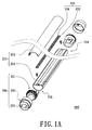
- FIG.1A is a partially-exploded schematic view of a lighting apparatus of a first embodiment of the present invention
- FIG. 1B is a partially-exploded schematic view of an adjustable assembly of FIG. 1A
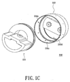
- FIG. 1C is another partially-exploded schematic view of the adjustable assembly of FIG. 1B
- FIG. 1D is a cross-sectional schematic view of the lighting apparatus of the first embodiment as the cap is at a first position
- FIG. 1E is a cross-sectional schematic view of the lighting apparatus of the first embodiment as the cap is at a second position.
- a lighting apparatus 200 includes a housing 210, a light source 220 and at least one adjustable assembly 230 (two adjustable assemblies 230 are schematically shown in FIG. 1A ).
- the housing 210 may include a transparent front portion 212 and a rigid back portion 214.
- the rigid back portion 214 may be a heat sink.
- the transparent front portion 212 may be sliding disposed at the rigid back portion 214 such that the transparent front portion 212 and the rigid back portion 214 together form an accommodating space 216.
- the light source 220 is disposed in the housing 210.
- the light source 220 may include a circuit board 222 and a plurality of LED elements 224.
- the LED elements 224 are electrically disposed on the circuit board 222.
- the circuit board 222 is disposed on the rigid back portion 214 such that the light source 220 is located in the accommodating space 216.
- the heat generated by the LED elements 224 can be transferred to the outside environment through a plurality of heat conductive channels (not shown) of the circuit board 222 and the rigid back portion 214 such as the heat sink.
- the adjustable assemblies 230 are disposed at two opposite ends 218 of the housing 210.
- Each of the adjustable assemblies 230 includes a connection element 231, a cap 232, at least one electrical terminal 233 (two electrical terminals 233 are schematically illustrated in FIG. 1B ) and an adjusting mechanism 234.
- the connection elements 231 of the adjustable assemblies 230 may be inserted into the rigid back portion 214 to be fixed to the ends 218 of the housing 210, respectively.
- the cap 232 of each adjustable assembly 230 caps the connection element 231, wherein the cap 232 includes a side wall 232a, an end wall 232b and an opening 232c.
- the side wall 232a is disposed at the end wall 232b
- the opening 232c is disposed at the side wall 232a and opposite to the end wall 232b
- the side wall 232a and the end wall 232b together form an accommodating space 232d
- the connection element 231 passes through the opening 232c
- a part of the connection element 231 is located in the accommodating space 232d.
- the electrical terminals 233 such as pins, are disposed at the end wall 232b and extend outside the cap 232.
- the electrical terminals 233 are electrically connected to the circuit board 222 of the light source 220.
- the electrical terminals 233 can be electrically connected to the circuit board 222 of the light source 220 through wires (not shown).
- the electrical terminals 233 of each of the adjustable assemblies 230 can be inserted into one of two sockets of a standard fluorescent or incandescent light fixture (not shown).
- the adjusting mechanism 234 includes a gear 234a, a positioning element 234b, a clasp 234c and a track 234d.
- the positioning element 234b is, for example, a protrusion
- the clasp 234c is, for example, a protrusion.
- One of the gear 234a and the positioning element 234b (e.g. the gear 234a) is disposed at the connection element 231, the other of the gear 234a and the positioning element 234b (e.g. the positioning element 234b) is disposed at the cap 232 and located in the accommodating space 232d.
- One of the clasp 234c and the track 234d (e.g.
- the track 234d is disposed at the connection element 231
- the other of the clasp 234c and the track 234d e.g. the clasp 234c
- the positioning element 234b is disposed at the connection element 231
- the gear 234a is disposed at the cap 232 and located in the accommodating space 232d
- the clasp 234c is disposed at the connection element 231
- the track 234d is disposed at the cap 232 and located in the accommodating space 232d.
- each adjustable assembly 230 when the cap 232 of each adjustable assembly 230 is at a first position, the positioning element 234b is engaged with the gear 234a to be restricted by the gear 234a such that the cap 232 is not rotated relative to the connection element 231.
- the positioning element 234b when the cap 232 of each adjustable assembly 230 is at a second position, the positioning element 234b is not restricted by the gear 234a and the clasp 234c is disposed at the track 234d such that the cap 232 is adapted to be rotated relative to the connection element 231 and the clasp 234c is adapted to slide along the track 234d to direct the light from the LED elements 224 to illuminate the desired surface or area.
- the track 234d has a first trench T1 and a second trench T2, wherein the clasp 234c clasps the first trench T1 when the cap 232 is at the first position, and the clasp 234c is disposed at the second trench T2 when the cap 232 is at the second position.
- the user can shift the caps 232 to the first position such that the final position of the housing 210 and the connection elements 231 is maintained. Because the caps 232 can be shifted to the second position to disengage the positioning element 234b and the gear 234a such that the housing 210 and the connection elements 231 can be rotated relative to the caps 232.
- the lighting apparatus 200 of the first embodiment is applicable to the present exiting light fixture and the light from the lighting source 220 can be directed to illuminate the desired surface or area.
- FIG. 2A is a partially-exploded schematic view of a lighting apparatus of a second embodiment of the present invention.
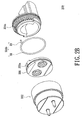
- FIG. 2B is a partially-exploded schematic view of an adjustable assembly of a second embodiment of the present invention
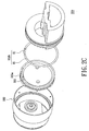
- FIG. 2C is another partially-exploded schematic view of the adjustable assembly of FIG. 2A
- FIG. 2D is a cross-sectional schematic view of the adjustable assembly of the second embodiment as the cap is at a first position
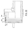
- FIG. 2E is a cross-sectional schematic view of the adjustable assembly of the second embodiment as the cap is at a second position.
- each of the adjustable assemblies 330 of the lighting apparatus further includes a medium element 335 disposed in the cap 332, the positioning element 334b includes a ring-shaped body B1 encircling the medium element 335 and a rod R1 disposed at the ring-shaped body B1. More specifically, the medium element 335 has a trench 335a and the ring-shaped body B1 is disposed in the trench 335a to encircling the medium element 335. The rod R1 is engaged with the gear 334a when the cap 332 is at the first position (shown in FIG. 2D ).
- the lighting apparatus of the second embodiment is applicable to the present exiting light fixture and the light from the lighting source 320 can be directed to illuminate the desired surface or area.
- the lighting apparatus of each of the embodiments is applicable to the present exiting light fixture and the light from the lighting source can be directed to illuminate the desired surface or area.
Landscapes
- Engineering & Computer Science (AREA)
- Physics & Mathematics (AREA)
- Microelectronics & Electronic Packaging (AREA)
- Optics & Photonics (AREA)
- General Engineering & Computer Science (AREA)
- Non-Portable Lighting Devices Or Systems Thereof (AREA)
- Fastening Of Light Sources Or Lamp Holders (AREA)
Description
- The present invention relates generally to an electrical apparatus. More particularly, the present invention relates to a lighting apparatus.
- Commercial light fixtures commonly use fluorescent lamps or incandescent lamps to radiate light for illumination. These lighting fixtures have the common drawbacks of high power consumption, quick light attenuation, short service life, fragility, and the inability to be reclaimed. Light emitting diode elements (hereinafter LED elements) may be used to replace fluorescent or incandescent bulbs to obtain the environmental and economic benefits of LED technology. However, LED elements are directional and when used with exiting light fixtures, they do not necessarily provide the illumination where it is needed.
- Standard light tubes are mounted in a light fixture by means of sliding connector pins into end sockets and then turning the tube 90 degrees so that the pins engage electrical contacts in the sockets. The lamp tube emits light omni-directionally and its orientation in the sockets is of no consequence, making orientation of pin connectors on different models of fixtures inconsequential. However, LED elements emit light generally at a narrowly-angled conical path. An LED lighting tube retrofitted into the exiting light fixture may not be oriented to emit light in the desired direction as the angular presentation of the light to the surface to be illuminated can be offset by the variation of the pin connectors.
- A retro-fit LED lighting apparatus with a light direction adjustment possibility is known from
US-A-2009/159919 , which discloses all features of the preamble ofclaim 1. - The present invention is directed to provide a lighting apparatus with an improved adjustable assembly.
- In one embodiment, a lighting apparatus includes a housing, a light source and at least one adjustable assembly. The light source is disposed in the housing, and the adjustable assembly is disposed at an end of the housing and includes a connection element, a cap, at least one electrical terminal and an adjusting mechanism. The connection element is fixed to the end of the housing. The cap caps the connection element, wherein the cap includes a side wall, an end wall and an opening, the side wall is disposed at the end wall, the opening is disposed at the side wall and opposite to the end wall, the side wall and the end wall together form an accommodating space, the connection element passes through the opening, and a part of the connection element is located in the accommodating space. The electrical terminal is disposed at the end wall and extends outside the cap. The electrical terminal is electrically connected to the light source. The adjusting mechanism includes a gear, a positioning element, a clasp and a track. One of the gear and the positioning element is disposed at the connection element, the other of the gear and the positioning element is disposed at the cap and located in the accommodating space, one of the clasp and the track is disposed at the connection element, and the other of the clasp and the track is disposed at the cap and located in the accommodating space. When the cap is at a first position, the positioning element is engaged with the gear to be restricted by the gear such that the cap is not rotated relative to the connection element. When the cap is at a second position, the positioning element is not restricted by the gear and the clasp is disposed at the track such that the cap is adapted to be rotated relative to the connection element and the clasp is adapted to slide along the track.
- In one embodiment of the present invention, the track has a first trench and a second trench, wherein the clasp clasps the first trench when the cap is at the first position, and the clasp is disposed at the second trench when the cap is at the second position.
- In one embodiment of the present invention, the positioning element is a protrusion.
- In one embodiment of the present invention, the adjusting assembly further includes a medium element disposed in the cap, the positioning element includes a ring-shaped body encircling the medium element and a rod disposed at the ring-shaped body. The rod is engaged with the gear when the cap is at the first position.
- In one embodiment of the present invention, the clasp is a protrusion.
- Because the housing and the connection element of the lighting apparatus of each of the embodiments can be rotated relative to the cap, the lighting apparatus of each of the embodiments is applicable to the present exiting light fixture and the light from the lighting source can be directed to illuminate the desired surface or area.
- Other objectives, features and advantages of the present invention will be further understood from the further technological features disclosed by the embodiments of the present invention wherein there are shown and described preferred embodiments of this invention, simply by way of illustration of modes best suited to carry out the invention.
- The accompanying drawings are included to provide a further understanding of the invention, and are incorporated in and constitute part of this specification. The drawings illustrate embodiments of the invention and, together with the description, serve to explain the principles of the invention.
-
FIG.1A is a partially-exploded schematic view of a lighting apparatus of a first embodiment of the present invention. -
FIG. 1B is a partially-exploded schematic view of an adjustable assembly ofFIG. 1A . -
FIG. 1C is another partially-exploded schematic view of the adjustable assembly ofFIG. 1B . -
FIG. 1D is a cross-sectional schematic view of the lighting apparatus of the first embodiment as the cap is at a first position. -
FIG. 1E is a cross-sectional schematic view of the lighting apparatus of the first embodiment as the cap is at a second position. -
FIG. 2A is a partially-exploded schematic view of a lighting apparatus of a second embodiment of the present invention. -
FIG. 2B is a partially-exploded schematic view of an adjustable assembly of a second embodiment of the present invention. -
FIG. 2C is another partially-exploded schematic view of the adjustable assembly ofFIG. 2A . -
FIG. 2D is a cross-sectional schematic view of the adjustable assembly of the second embodiment as the cap is at a first position. -
FIG. 2E is a cross-sectional schematic view of the adjustable assembly of the second embodiment as the cap is at a second position. - Reference will now be made to the drawings to describe exemplary embodiments of the present sensing system, in detail. The following description is given by way of example, and not limitation.
-
FIG.1A is a partially-exploded schematic view of a lighting apparatus of a first embodiment of the present invention,FIG. 1B is a partially-exploded schematic view of an adjustable assembly ofFIG. 1A ,FIG. 1C is another partially-exploded schematic view of the adjustable assembly ofFIG. 1B ,FIG. 1D is a cross-sectional schematic view of the lighting apparatus of the first embodiment as the cap is at a first position, andFIG. 1E is a cross-sectional schematic view of the lighting apparatus of the first embodiment as the cap is at a second position. Referring toFIGS 1A to 1E , alighting apparatus 200 includes ahousing 210, alight source 220 and at least one adjustable assembly 230 (twoadjustable assemblies 230 are schematically shown inFIG. 1A ). Thehousing 210 may include a transparentfront portion 212 and arigid back portion 214. Therigid back portion 214 may be a heat sink. Thetransparent front portion 212 may be sliding disposed at therigid back portion 214 such that thetransparent front portion 212 and therigid back portion 214 together form anaccommodating space 216. - The
light source 220 is disposed in thehousing 210. Particularly, thelight source 220 may include acircuit board 222 and a plurality ofLED elements 224. TheLED elements 224 are electrically disposed on thecircuit board 222. Thecircuit board 222 is disposed on therigid back portion 214 such that thelight source 220 is located in theaccommodating space 216. When theLED elements 224 operate to illuminate light, the heat generated by theLED elements 224 can be transferred to the outside environment through a plurality of heat conductive channels (not shown) of thecircuit board 222 and therigid back portion 214 such as the heat sink. - The
adjustable assemblies 230 are disposed at twoopposite ends 218 of thehousing 210. Each of theadjustable assemblies 230 includes aconnection element 231, acap 232, at least one electrical terminal 233 (twoelectrical terminals 233 are schematically illustrated inFIG. 1B ) and anadjusting mechanism 234. Theconnection elements 231 of theadjustable assemblies 230 may be inserted into therigid back portion 214 to be fixed to theends 218 of thehousing 210, respectively. Thecap 232 of eachadjustable assembly 230 caps theconnection element 231, wherein thecap 232 includes aside wall 232a, anend wall 232b and anopening 232c. Theside wall 232a is disposed at theend wall 232b, theopening 232c is disposed at theside wall 232a and opposite to theend wall 232b, theside wall 232a and theend wall 232b together form anaccommodating space 232d, theconnection element 231 passes through theopening 232c, and a part of theconnection element 231 is located in theaccommodating space 232d. Theelectrical terminals 233, such as pins, are disposed at theend wall 232b and extend outside thecap 232. Theelectrical terminals 233 are electrically connected to thecircuit board 222 of thelight source 220. In one embodiment, theelectrical terminals 233 can be electrically connected to thecircuit board 222 of thelight source 220 through wires (not shown). Theelectrical terminals 233 of each of theadjustable assemblies 230 can be inserted into one of two sockets of a standard fluorescent or incandescent light fixture (not shown). - In each of the
adjustable assemblies 230, theadjusting mechanism 234 includes agear 234a, apositioning element 234b, aclasp 234c and atrack 234d. Thepositioning element 234b is, for example, a protrusion, and theclasp 234c is, for example, a protrusion. One of thegear 234a and thepositioning element 234b (e.g. thegear 234a) is disposed at theconnection element 231, the other of thegear 234a and thepositioning element 234b (e.g. thepositioning element 234b) is disposed at thecap 232 and located in theaccommodating space 232d. One of theclasp 234c and thetrack 234d (e.g. thetrack 234d) is disposed at theconnection element 231, and the other of theclasp 234c and thetrack 234d (e.g. theclasp 234c) is disposed at thecap 232 and located in theaccommodating space 232d. In another embodiment, thepositioning element 234b is disposed at theconnection element 231, thegear 234a is disposed at thecap 232 and located in theaccommodating space 232d, theclasp 234c is disposed at theconnection element 231, and thetrack 234d is disposed at thecap 232 and located in theaccommodating space 232d. - Referring to
FIG. 1D , when thecap 232 of eachadjustable assembly 230 is at a first position, thepositioning element 234b is engaged with thegear 234a to be restricted by thegear 234a such that thecap 232 is not rotated relative to theconnection element 231. Referring toFIG. 1E , when thecap 232 of eachadjustable assembly 230 is at a second position, thepositioning element 234b is not restricted by thegear 234a and theclasp 234c is disposed at thetrack 234d such that thecap 232 is adapted to be rotated relative to theconnection element 231 and theclasp 234c is adapted to slide along thetrack 234d to direct the light from theLED elements 224 to illuminate the desired surface or area. In one embodiment, thetrack 234d has a first trench T1 and a second trench T2, wherein theclasp 234c clasps the first trench T1 when thecap 232 is at the first position, and theclasp 234c is disposed at the second trench T2 when thecap 232 is at the second position. - When the
housing 210 and theconnection elements 231 are adjusted to an adequate position, the user can shift thecaps 232 to the first position such that the final position of thehousing 210 and theconnection elements 231 is maintained. Because thecaps 232 can be shifted to the second position to disengage thepositioning element 234b and thegear 234a such that thehousing 210 and theconnection elements 231 can be rotated relative to thecaps 232. Thelighting apparatus 200 of the first embodiment is applicable to the present exiting light fixture and the light from thelighting source 220 can be directed to illuminate the desired surface or area. -
FIG. 2A is a partially-exploded schematic view of a lighting apparatus of a second embodiment of the present invention.FIG. 2B is a partially-exploded schematic view of an adjustable assembly of a second embodiment of the present invention,FIG. 2C is another partially-exploded schematic view of the adjustable assembly ofFIG. 2A ,FIG. 2D is a cross-sectional schematic view of the adjustable assembly of the second embodiment as the cap is at a first position, andFIG. 2E is a cross-sectional schematic view of the adjustable assembly of the second embodiment as the cap is at a second position. Referring toFIGS. 2A to 2E , the main difference between thelighting apparatus 300 of the second embodiment and thelighting apparatus 200 of the first embodiment lies in that each of theadjustable assemblies 330 of the lighting apparatus further includes amedium element 335 disposed in thecap 332, thepositioning element 334b includes a ring-shaped body B1 encircling themedium element 335 and a rod R1 disposed at the ring-shaped body B1. More specifically, themedium element 335 has atrench 335a and the ring-shaped body B1 is disposed in thetrench 335a to encircling themedium element 335. The rod R1 is engaged with thegear 334a when thecap 332 is at the first position (shown inFIG. 2D ). - Because the
caps 332 can be shifted to the second position to disengage the rod R1 of thepositioning element 334b and thegear 334a such that the housing 310 and the connection elements 331 can be rotated relative to thecaps 332. The lighting apparatus of the second embodiment is applicable to the present exiting light fixture and the light from the lighting source 320 can be directed to illuminate the desired surface or area. - According to the above description, because the housing and the connection element of the lighting apparatus of each of the embodiments can be rotated relative to the cap, the lighting apparatus of each of the embodiments is applicable to the present exiting light fixture and the light from the lighting source can be directed to illuminate the desired surface or area.
- The above description is given by way of example, and not limitation. Given the above disclosure, one skilled in the art could devise variations that are within the scope and spirit of the invention disclosed herein, including configurations ways of the recessed portions and materials and/or designs of the attaching structures. Further, the various features of the embodiments disclosed herein can be used alone, or in varying combinations with each other and are not intended to be limited to the specific combination described herein. Thus, the scope of the claims is not to be limited by the illustrated embodiments. The scope of the invention is defined by the claims.
Claims (5)
- A lighting apparatus comprising:a housing (210);a light source (220) disposed in the housing; andat least one adjustable assembly (230) disposed at an end of the housing and comprising:a connection element (231) fixed to the end of the housing;a cap (232) capping the connection element, wherein the cap comprises a side wall (232a), an end wall (232b) and an opening (232c), the side wall is disposed at the end wall, the opening is disposed at the side wall and opposite to the end wall, the side wall and the end wall together form an accommodating space (232d), the connection element passes through the opening, and a part of the connection element is located in the accommodating space;at least one electrical terminal (233) disposed at the end wall and extending outside the cap, wherein the electrical terminal is electrically connected to the light source; and characterised by: an adjusting mechanism comprising a gear (234a), a positioning element (234b), a clasp (234c) and a track (234d); wherein one of the gear and the positioning element is disposed at the connection element (231), the other of the gear and the positioning element is disposed at the cap (232) and located in the accommodating space, one of the clasp and the track is disposed at the connection element, and the other of the clasp and the track is disposed at the cap and located in the accommodating space;when the cap is at a first position, the positioning element (234b) is engaged with the gear (234a) to be restricted by the gear such that the cap is not rotated relative to the connection element;when the cap is at a second position, the positioning element is not restricted by the gear and the clasp (234c) is disposed at the track (234d) such that the cap is adapted to be rotated relative to the connection element and the clasp is adapted to slide along the track.
- The lighting apparatus as claimed in claim 1, wherein the track (234d) has a first trench (T1) and a second trench (T2); wherein the clasp (234c) clasps the first trench when the cap is at the first position, and the clasp is disposed at the second trench when the cap is at the second position.
- The lighting apparatus as claimed in claim 1, wherein the positioning element (234b) is a protrusion.
- The lighting apparatus as claimed in claim 1, wherein the adjusting assembly further comprises a medium element (335) disposed in the cap (332), the positioning element (334b) comprises a ring-shaped body (B1) encircling the medium element and a rod (R1) disposed at the ring-shaped body, and the rod is engaged with the gear when the cap is at the first position.
- The lighting apparatus as claimed in claim 1, wherein the clasp (234c) is a protrusion.
Applications Claiming Priority (1)
| Application Number | Priority Date | Filing Date | Title |
|---|---|---|---|
| US12/703,284 US8157408B2 (en) | 2010-02-10 | 2010-02-10 | Lighting apparatus |
Publications (3)
| Publication Number | Publication Date |
|---|---|
| EP2354650A2 EP2354650A2 (en) | 2011-08-10 |
| EP2354650A3 EP2354650A3 (en) | 2012-05-02 |
| EP2354650B1 true EP2354650B1 (en) | 2014-04-30 |
Family
ID=44009993
Family Applications (1)
| Application Number | Title | Priority Date | Filing Date |
|---|---|---|---|
| EP11153195.0A Not-in-force EP2354650B1 (en) | 2010-02-10 | 2011-02-03 | Lighting apparatus |
Country Status (2)
| Country | Link |
|---|---|
| US (1) | US8157408B2 (en) |
| EP (1) | EP2354650B1 (en) |
Families Citing this family (24)
| Publication number | Priority date | Publication date | Assignee | Title |
|---|---|---|---|---|
| US8905579B2 (en) * | 2006-10-24 | 2014-12-09 | Ellenby Technologies, Inc. | Vending machine having LED lamp with control and communication circuits |
| CN102200226A (en) * | 2010-03-23 | 2011-09-28 | 欧司朗有限公司 | Self-ballasting light emitting diode (LED) lamp tube and lamp with same |
| DE102010003717A1 (en) * | 2010-04-08 | 2011-10-13 | Osram Gesellschaft mit beschränkter Haftung | Lamp and end cap for a lamp |
| US8604712B2 (en) * | 2010-08-17 | 2013-12-10 | Keystone L.E.D. Holdings Llc | LED luminaires power supply |
| US8827486B2 (en) * | 2011-02-21 | 2014-09-09 | Lextar Electronics Corporation | Lamp tube structure and assembly thereof |
| CN102086986B (en) * | 2011-02-28 | 2013-01-09 | 鸿富锦精密工业(深圳)有限公司 | LED (light-emitting diode) lighting tube |
| CN202302808U (en) * | 2011-09-07 | 2012-07-04 | 欧司朗股份有限公司 | Lamp seat for light-emitting diode (LED) luminescent device and LED luminescent assembly |
| TWM429803U (en) * | 2011-10-21 | 2012-05-21 | Wintek Corp | Rotatable illumination device |
| DE202011107688U1 (en) * | 2011-11-10 | 2012-01-12 | Jakob Radtke | lighting device |
| TWI480486B (en) * | 2012-03-20 | 2015-04-11 | Delta Electronics Inc | Lamp module and connection mechanism thereof |
| US8628342B2 (en) * | 2012-06-04 | 2014-01-14 | Rv Lighting | Swivel adaptor |
| JP2014029824A (en) * | 2012-07-04 | 2014-02-13 | Sankei Co Ltd | Fluorescent lamp type semiconductor lamp and sleeve parts of the same |
| TW201413162A (en) * | 2012-09-27 | 2014-04-01 | Justing Tech Taiwan Pte Ltd | Light-emitting diode light tube connector |
| CN103822178A (en) * | 2012-11-16 | 2014-05-28 | 通用电气照明解决方案有限责任公司 | Rotating cap for light source field |
| CN104235768B (en) * | 2013-06-18 | 2019-02-22 | 朗德万斯公司 | The end cap of fluorescent tube and the lighting device for using the end cap |
| JP6131734B2 (en) * | 2013-06-21 | 2017-05-24 | 株式会社リコー | Straight tube LED lamp and lighting device |
| US9726330B2 (en) | 2013-12-20 | 2017-08-08 | Cree, Inc. | LED lamp |
| CN105098551B (en) | 2014-05-19 | 2019-01-25 | 朗德万斯公司 | Electrical connector and lighting device including the electrical connector |
| DE102014214175A1 (en) * | 2014-07-21 | 2016-01-21 | Osram Gmbh | Twistable base for lamp tube |
| TWI564507B (en) * | 2014-10-22 | 2017-01-01 | 隆達電子股份有限公司 | Rotatable lamp cap structure and rotatable lamp tube |
| CN106410539B (en) * | 2015-07-28 | 2020-01-03 | 朗德万斯公司 | Electrical connector and lighting device |
| CN106439751B (en) * | 2015-08-04 | 2019-11-26 | 朗德万斯公司 | Electrical connector and lighting device |
| US10253954B2 (en) * | 2015-11-16 | 2019-04-09 | Banner Engineering Corp. | Longitudinal stress mitigation for elongate LED luminaires |
| CN109296952B (en) * | 2018-08-17 | 2024-05-10 | 赛尔富电子有限公司 | Angle-adjustable lamp |
Family Cites Families (5)
| Publication number | Priority date | Publication date | Assignee | Title |
|---|---|---|---|---|
| US7052171B1 (en) * | 2004-12-15 | 2006-05-30 | Emteq, Inc. | Lighting assembly with swivel end connectors |
| US7270443B2 (en) * | 2006-01-13 | 2007-09-18 | Richard Kurtz | Directional adjustable swivel lighting-fixture |
| US20090091929A1 (en) * | 2007-10-05 | 2009-04-09 | Faubion Associates, Inc. | Directional l.e.d. lighting unit for retrofit applications |
| US8118447B2 (en) * | 2007-12-20 | 2012-02-21 | Altair Engineering, Inc. | LED lighting apparatus with swivel connection |
| US7594738B1 (en) * | 2008-07-02 | 2009-09-29 | Cpumate Inc. | LED lamp with replaceable power supply |
-
2010
- 2010-02-10 US US12/703,284 patent/US8157408B2/en not_active Expired - Fee Related
-
2011
- 2011-02-03 EP EP11153195.0A patent/EP2354650B1/en not_active Not-in-force
Also Published As
| Publication number | Publication date |
|---|---|
| US20110194278A1 (en) | 2011-08-11 |
| EP2354650A2 (en) | 2011-08-10 |
| US8157408B2 (en) | 2012-04-17 |
| EP2354650A3 (en) | 2012-05-02 |
Similar Documents
| Publication | Publication Date | Title |
|---|---|---|
| US8167452B2 (en) | Lighting apparatus | |
| EP2354650A2 (en) | Lighting apparatus | |
| CN1955774B (en) | LED lamp source | |
| US9765935B2 (en) | LED lamp with LED board brace | |
| CN102089938B (en) | Two-pin connector and lamp using the same | |
| JP6010116B2 (en) | Socket, lighting module, and lighting fixture | |
| EP2781822A1 (en) | Lamp device and luminaire | |
| JP5662065B2 (en) | Straight tube lamp and lighting device | |
| JP2014523097A (en) | Lamp tube | |
| US20140286021A1 (en) | Lamp Device and Luminaire | |
| KR101140162B1 (en) | Tube type led lamp assembly | |
| US10222006B2 (en) | Tubular lamp and lamp socket with power pin connector and signal pin connector | |
| RU2616965C2 (en) | Control interface module | |
| JP5845050B2 (en) | Vehicle lighting | |
| JP7513317B2 (en) | LED lighting equipment | |
| JP5132007B2 (en) | lighting equipment | |
| US20140286014A1 (en) | Lamp Device and Luminaire | |
| KR101077477B1 (en) | LED illuminator | |
| WO2013108666A1 (en) | Light fixture for vehicle | |
| US12455050B1 (en) | LED tube lighting device having uniform light distribution | |
| JP5736500B2 (en) | Straight tube lamp and lighting device | |
| CA2746820A1 (en) | Adapter, particularly for adapting light emitting diodes to commercial lamp-holders | |
| JP2011171070A (en) | Illumination fixture | |
| JP2023148734A (en) | lighting equipment | |
| US10322665B2 (en) | Holding device for lamps in vehicle lights having a plate-like section with receptacle providing space for different types of lamps and vehicle light |
Legal Events
| Date | Code | Title | Description |
|---|---|---|---|
| PUAI | Public reference made under article 153(3) epc to a published international application that has entered the european phase |
Free format text: ORIGINAL CODE: 0009012 |
|
| 17P | Request for examination filed |
Effective date: 20110224 |
|
| AK | Designated contracting states |
Kind code of ref document: A2 Designated state(s): AL AT BE BG CH CY CZ DE DK EE ES FI FR GB GR HR HU IE IS IT LI LT LU LV MC MK MT NL NO PL PT RO RS SE SI SK SM TR |
|
| AX | Request for extension of the european patent |
Extension state: BA ME |
|
| PUAL | Search report despatched |
Free format text: ORIGINAL CODE: 0009013 |
|
| AK | Designated contracting states |
Kind code of ref document: A3 Designated state(s): AL AT BE BG CH CY CZ DE DK EE ES FI FR GB GR HR HU IE IS IT LI LT LU LV MC MK MT NL NO PL PT RO RS SE SI SK SM TR |
|
| AX | Request for extension of the european patent |
Extension state: BA ME |
|
| RIC1 | Information provided on ipc code assigned before grant |
Ipc: F21K 99/00 20100101ALI20120328BHEP Ipc: F21V 19/02 20060101AFI20120328BHEP Ipc: F21V 14/02 20060101ALN20120328BHEP |
|
| GRAP | Despatch of communication of intention to grant a patent |
Free format text: ORIGINAL CODE: EPIDOSNIGR1 |
|
| RIC1 | Information provided on ipc code assigned before grant |
Ipc: F21V 14/02 20060101ALN20130930BHEP Ipc: F21Y 101/02 20060101ALI20130930BHEP Ipc: F21K 99/00 20100101ALI20130930BHEP Ipc: F21V 19/02 20060101AFI20130930BHEP Ipc: F21Y 103/00 20060101ALI20130930BHEP |
|
| INTG | Intention to grant announced |
Effective date: 20131024 |
|
| GRAS | Grant fee paid |
Free format text: ORIGINAL CODE: EPIDOSNIGR3 |
|
| GRAP | Despatch of communication of intention to grant a patent |
Free format text: ORIGINAL CODE: EPIDOSNIGR1 |
|
| RIC1 | Information provided on ipc code assigned before grant |
Ipc: F21Y 101/02 20060101ALI20140218BHEP Ipc: F21V 14/02 20060101ALN20140218BHEP Ipc: F21V 19/02 20060101AFI20140218BHEP Ipc: F21K 99/00 20100101ALI20140218BHEP Ipc: F21Y 103/00 20060101ALI20140218BHEP |
|
| GRAA | (expected) grant |
Free format text: ORIGINAL CODE: 0009210 |
|
| INTG | Intention to grant announced |
Effective date: 20140306 |
|
| AK | Designated contracting states |
Kind code of ref document: B1 Designated state(s): AL AT BE BG CH CY CZ DE DK EE ES FI FR GB GR HR HU IE IS IT LI LT LU LV MC MK MT NL NO PL PT RO RS SE SI SK SM TR |
|
| REG | Reference to a national code |
Ref country code: GB Ref legal event code: FG4D Ref country code: CH Ref legal event code: EP |
|
| REG | Reference to a national code |
Ref country code: AT Ref legal event code: REF Ref document number: 665396 Country of ref document: AT Kind code of ref document: T Effective date: 20140515 |
|
| REG | Reference to a national code |
Ref country code: IE Ref legal event code: FG4D |
|
| REG | Reference to a national code |
Ref country code: DE Ref legal event code: R096 Ref document number: 602011006462 Country of ref document: DE Effective date: 20140612 |
|
| REG | Reference to a national code |
Ref country code: NL Ref legal event code: T3 |
|
| REG | Reference to a national code |
Ref country code: AT Ref legal event code: MK05 Ref document number: 665396 Country of ref document: AT Kind code of ref document: T Effective date: 20140430 |
|
| REG | Reference to a national code |
Ref country code: LT Ref legal event code: MG4D |
|
| PG25 | Lapsed in a contracting state [announced via postgrant information from national office to epo] |
Ref country code: BG Free format text: LAPSE BECAUSE OF FAILURE TO SUBMIT A TRANSLATION OF THE DESCRIPTION OR TO PAY THE FEE WITHIN THE PRESCRIBED TIME-LIMIT Effective date: 20140730 Ref country code: IS Free format text: LAPSE BECAUSE OF FAILURE TO SUBMIT A TRANSLATION OF THE DESCRIPTION OR TO PAY THE FEE WITHIN THE PRESCRIBED TIME-LIMIT Effective date: 20140830 Ref country code: FI Free format text: LAPSE BECAUSE OF FAILURE TO SUBMIT A TRANSLATION OF THE DESCRIPTION OR TO PAY THE FEE WITHIN THE PRESCRIBED TIME-LIMIT Effective date: 20140430 Ref country code: NO Free format text: LAPSE BECAUSE OF FAILURE TO SUBMIT A TRANSLATION OF THE DESCRIPTION OR TO PAY THE FEE WITHIN THE PRESCRIBED TIME-LIMIT Effective date: 20140730 Ref country code: GR Free format text: LAPSE BECAUSE OF FAILURE TO SUBMIT A TRANSLATION OF THE DESCRIPTION OR TO PAY THE FEE WITHIN THE PRESCRIBED TIME-LIMIT Effective date: 20140731 Ref country code: LT Free format text: LAPSE BECAUSE OF FAILURE TO SUBMIT A TRANSLATION OF THE DESCRIPTION OR TO PAY THE FEE WITHIN THE PRESCRIBED TIME-LIMIT Effective date: 20140430 Ref country code: CY Free format text: LAPSE BECAUSE OF FAILURE TO SUBMIT A TRANSLATION OF THE DESCRIPTION OR TO PAY THE FEE WITHIN THE PRESCRIBED TIME-LIMIT Effective date: 20140430 |
|
| PG25 | Lapsed in a contracting state [announced via postgrant information from national office to epo] |
Ref country code: PL Free format text: LAPSE BECAUSE OF FAILURE TO SUBMIT A TRANSLATION OF THE DESCRIPTION OR TO PAY THE FEE WITHIN THE PRESCRIBED TIME-LIMIT Effective date: 20140430 Ref country code: LV Free format text: LAPSE BECAUSE OF FAILURE TO SUBMIT A TRANSLATION OF THE DESCRIPTION OR TO PAY THE FEE WITHIN THE PRESCRIBED TIME-LIMIT Effective date: 20140430 Ref country code: SE Free format text: LAPSE BECAUSE OF FAILURE TO SUBMIT A TRANSLATION OF THE DESCRIPTION OR TO PAY THE FEE WITHIN THE PRESCRIBED TIME-LIMIT Effective date: 20140430 Ref country code: AT Free format text: LAPSE BECAUSE OF FAILURE TO SUBMIT A TRANSLATION OF THE DESCRIPTION OR TO PAY THE FEE WITHIN THE PRESCRIBED TIME-LIMIT Effective date: 20140430 Ref country code: HR Free format text: LAPSE BECAUSE OF FAILURE TO SUBMIT A TRANSLATION OF THE DESCRIPTION OR TO PAY THE FEE WITHIN THE PRESCRIBED TIME-LIMIT Effective date: 20140430 Ref country code: RS Free format text: LAPSE BECAUSE OF FAILURE TO SUBMIT A TRANSLATION OF THE DESCRIPTION OR TO PAY THE FEE WITHIN THE PRESCRIBED TIME-LIMIT Effective date: 20140430 Ref country code: ES Free format text: LAPSE BECAUSE OF FAILURE TO SUBMIT A TRANSLATION OF THE DESCRIPTION OR TO PAY THE FEE WITHIN THE PRESCRIBED TIME-LIMIT Effective date: 20140430 |
|
| PG25 | Lapsed in a contracting state [announced via postgrant information from national office to epo] |
Ref country code: PT Free format text: LAPSE BECAUSE OF FAILURE TO SUBMIT A TRANSLATION OF THE DESCRIPTION OR TO PAY THE FEE WITHIN THE PRESCRIBED TIME-LIMIT Effective date: 20140901 |
|
| PG25 | Lapsed in a contracting state [announced via postgrant information from national office to epo] |
Ref country code: SK Free format text: LAPSE BECAUSE OF FAILURE TO SUBMIT A TRANSLATION OF THE DESCRIPTION OR TO PAY THE FEE WITHIN THE PRESCRIBED TIME-LIMIT Effective date: 20140430 Ref country code: EE Free format text: LAPSE BECAUSE OF FAILURE TO SUBMIT A TRANSLATION OF THE DESCRIPTION OR TO PAY THE FEE WITHIN THE PRESCRIBED TIME-LIMIT Effective date: 20140430 Ref country code: DK Free format text: LAPSE BECAUSE OF FAILURE TO SUBMIT A TRANSLATION OF THE DESCRIPTION OR TO PAY THE FEE WITHIN THE PRESCRIBED TIME-LIMIT Effective date: 20140430 Ref country code: BE Free format text: LAPSE BECAUSE OF FAILURE TO SUBMIT A TRANSLATION OF THE DESCRIPTION OR TO PAY THE FEE WITHIN THE PRESCRIBED TIME-LIMIT Effective date: 20140430 Ref country code: RO Free format text: LAPSE BECAUSE OF FAILURE TO SUBMIT A TRANSLATION OF THE DESCRIPTION OR TO PAY THE FEE WITHIN THE PRESCRIBED TIME-LIMIT Effective date: 20140430 Ref country code: CZ Free format text: LAPSE BECAUSE OF FAILURE TO SUBMIT A TRANSLATION OF THE DESCRIPTION OR TO PAY THE FEE WITHIN THE PRESCRIBED TIME-LIMIT Effective date: 20140430 |
|
| REG | Reference to a national code |
Ref country code: DE Ref legal event code: R097 Ref document number: 602011006462 Country of ref document: DE |
|
| PLBE | No opposition filed within time limit |
Free format text: ORIGINAL CODE: 0009261 |
|
| STAA | Information on the status of an ep patent application or granted ep patent |
Free format text: STATUS: NO OPPOSITION FILED WITHIN TIME LIMIT |
|
| PG25 | Lapsed in a contracting state [announced via postgrant information from national office to epo] |
Ref country code: IT Free format text: LAPSE BECAUSE OF FAILURE TO SUBMIT A TRANSLATION OF THE DESCRIPTION OR TO PAY THE FEE WITHIN THE PRESCRIBED TIME-LIMIT Effective date: 20140430 |
|
| 26N | No opposition filed |
Effective date: 20150202 |
|
| REG | Reference to a national code |
Ref country code: DE Ref legal event code: R097 Ref document number: 602011006462 Country of ref document: DE Effective date: 20150202 |
|
| PG25 | Lapsed in a contracting state [announced via postgrant information from national office to epo] |
Ref country code: SI Free format text: LAPSE BECAUSE OF FAILURE TO SUBMIT A TRANSLATION OF THE DESCRIPTION OR TO PAY THE FEE WITHIN THE PRESCRIBED TIME-LIMIT Effective date: 20140430 |
|
| PG25 | Lapsed in a contracting state [announced via postgrant information from national office to epo] |
Ref country code: LU Free format text: LAPSE BECAUSE OF FAILURE TO SUBMIT A TRANSLATION OF THE DESCRIPTION OR TO PAY THE FEE WITHIN THE PRESCRIBED TIME-LIMIT Effective date: 20150203 |
|
| REG | Reference to a national code |
Ref country code: CH Ref legal event code: PL |
|
| PG25 | Lapsed in a contracting state [announced via postgrant information from national office to epo] |
Ref country code: CH Free format text: LAPSE BECAUSE OF NON-PAYMENT OF DUE FEES Effective date: 20150228 Ref country code: MC Free format text: LAPSE BECAUSE OF FAILURE TO SUBMIT A TRANSLATION OF THE DESCRIPTION OR TO PAY THE FEE WITHIN THE PRESCRIBED TIME-LIMIT Effective date: 20140430 Ref country code: LI Free format text: LAPSE BECAUSE OF NON-PAYMENT OF DUE FEES Effective date: 20150228 |
|
| REG | Reference to a national code |
Ref country code: IE Ref legal event code: MM4A |
|
| REG | Reference to a national code |
Ref country code: FR Ref legal event code: ST Effective date: 20151030 |
|
| PG25 | Lapsed in a contracting state [announced via postgrant information from national office to epo] |
Ref country code: IE Free format text: LAPSE BECAUSE OF NON-PAYMENT OF DUE FEES Effective date: 20150203 |
|
| PG25 | Lapsed in a contracting state [announced via postgrant information from national office to epo] |
Ref country code: FR Free format text: LAPSE BECAUSE OF NON-PAYMENT OF DUE FEES Effective date: 20150302 |
|
| PG25 | Lapsed in a contracting state [announced via postgrant information from national office to epo] |
Ref country code: MT Free format text: LAPSE BECAUSE OF FAILURE TO SUBMIT A TRANSLATION OF THE DESCRIPTION OR TO PAY THE FEE WITHIN THE PRESCRIBED TIME-LIMIT Effective date: 20140430 |
|
| PG25 | Lapsed in a contracting state [announced via postgrant information from national office to epo] |
Ref country code: HU Free format text: LAPSE BECAUSE OF FAILURE TO SUBMIT A TRANSLATION OF THE DESCRIPTION OR TO PAY THE FEE WITHIN THE PRESCRIBED TIME-LIMIT; INVALID AB INITIO Effective date: 20110203 Ref country code: SM Free format text: LAPSE BECAUSE OF FAILURE TO SUBMIT A TRANSLATION OF THE DESCRIPTION OR TO PAY THE FEE WITHIN THE PRESCRIBED TIME-LIMIT Effective date: 20140430 |
|
| PG25 | Lapsed in a contracting state [announced via postgrant information from national office to epo] |
Ref country code: TR Free format text: LAPSE BECAUSE OF FAILURE TO SUBMIT A TRANSLATION OF THE DESCRIPTION OR TO PAY THE FEE WITHIN THE PRESCRIBED TIME-LIMIT Effective date: 20140430 |
|
| PG25 | Lapsed in a contracting state [announced via postgrant information from national office to epo] |
Ref country code: MK Free format text: LAPSE BECAUSE OF FAILURE TO SUBMIT A TRANSLATION OF THE DESCRIPTION OR TO PAY THE FEE WITHIN THE PRESCRIBED TIME-LIMIT Effective date: 20140430 |
|
| PG25 | Lapsed in a contracting state [announced via postgrant information from national office to epo] |
Ref country code: AL Free format text: LAPSE BECAUSE OF FAILURE TO SUBMIT A TRANSLATION OF THE DESCRIPTION OR TO PAY THE FEE WITHIN THE PRESCRIBED TIME-LIMIT Effective date: 20140430 |
|
| RIC2 | Information provided on ipc code assigned after grant |
Ipc: F21K 99/00 20160101ALI20140218BHEP Ipc: F21V 19/02 20060101AFI20140218BHEP Ipc: F21Y 103/00 20160101ALI20140218BHEP Ipc: F21V 14/02 20060101ALN20140218BHEP Ipc: F21Y 101/02 20000101ALI20140218BHEP |
|
| PGFP | Annual fee paid to national office [announced via postgrant information from national office to epo] |
Ref country code: NL Payment date: 20190225 Year of fee payment: 9 |
|
| PGFP | Annual fee paid to national office [announced via postgrant information from national office to epo] |
Ref country code: DE Payment date: 20190124 Year of fee payment: 9 Ref country code: GB Payment date: 20190128 Year of fee payment: 9 |
|
| REG | Reference to a national code |
Ref country code: DE Ref legal event code: R119 Ref document number: 602011006462 Country of ref document: DE |
|
| REG | Reference to a national code |
Ref country code: NL Ref legal event code: MM Effective date: 20200301 |
|
| GBPC | Gb: european patent ceased through non-payment of renewal fee |
Effective date: 20200203 |
|
| PG25 | Lapsed in a contracting state [announced via postgrant information from national office to epo] |
Ref country code: NL Free format text: LAPSE BECAUSE OF NON-PAYMENT OF DUE FEES Effective date: 20200301 |
|
| PG25 | Lapsed in a contracting state [announced via postgrant information from national office to epo] |
Ref country code: GB Free format text: LAPSE BECAUSE OF NON-PAYMENT OF DUE FEES Effective date: 20200203 Ref country code: DE Free format text: LAPSE BECAUSE OF NON-PAYMENT OF DUE FEES Effective date: 20200901 |