EP2354453A1 - Turbine engine component for adaptive cooling - Google Patents
Turbine engine component for adaptive cooling Download PDFInfo
- Publication number
- EP2354453A1 EP2354453A1 EP10152428A EP10152428A EP2354453A1 EP 2354453 A1 EP2354453 A1 EP 2354453A1 EP 10152428 A EP10152428 A EP 10152428A EP 10152428 A EP10152428 A EP 10152428A EP 2354453 A1 EP2354453 A1 EP 2354453A1
- Authority
- EP
- European Patent Office
- Prior art keywords
- depression
- turbine engine
- engine component
- back face
- body portion
- Prior art date
- Legal status (The legal status is an assumption and is not a legal conclusion. Google has not performed a legal analysis and makes no representation as to the accuracy of the status listed.)
- Granted
Links
- 238000001816 cooling Methods 0.000 title claims description 48
- 230000003044 adaptive effect Effects 0.000 title claims description 4
- 239000012809 cooling fluid Substances 0.000 claims abstract description 26
- 239000012530 fluid Substances 0.000 claims abstract description 16
- 230000007423 decrease Effects 0.000 claims abstract description 11
- 239000000463 material Substances 0.000 claims description 24
- 230000003647 oxidation Effects 0.000 claims description 17
- 238000007254 oxidation reaction Methods 0.000 claims description 17
- 239000011248 coating agent Substances 0.000 claims description 15
- 238000000576 coating method Methods 0.000 claims description 15
- 238000005260 corrosion Methods 0.000 claims description 9
- 230000007797 corrosion Effects 0.000 claims description 9
- 230000003628 erosive effect Effects 0.000 claims description 9
- 230000000694 effects Effects 0.000 claims description 5
- 238000000034 method Methods 0.000 claims description 4
- 230000003068 static effect Effects 0.000 claims description 2
- 230000007704 transition Effects 0.000 claims description 2
- 239000007789 gas Substances 0.000 description 19
- 238000004519 manufacturing process Methods 0.000 description 5
- 230000008901 benefit Effects 0.000 description 4
- 239000003779 heat-resistant material Substances 0.000 description 4
- 238000009434 installation Methods 0.000 description 4
- 238000002844 melting Methods 0.000 description 4
- 230000008018 melting Effects 0.000 description 4
- 238000005266 casting Methods 0.000 description 3
- 239000012720 thermal barrier coating Substances 0.000 description 3
- 238000002485 combustion reaction Methods 0.000 description 2
- 230000001419 dependent effect Effects 0.000 description 2
- 238000005297 material degradation process Methods 0.000 description 2
- 238000012986 modification Methods 0.000 description 2
- 230000004048 modification Effects 0.000 description 2
- 230000009467 reduction Effects 0.000 description 2
- 238000000859 sublimation Methods 0.000 description 2
- 230000008022 sublimation Effects 0.000 description 2
- 241000826860 Trapezium Species 0.000 description 1
- 238000013459 approach Methods 0.000 description 1
- 239000000919 ceramic Substances 0.000 description 1
- 230000008859 change Effects 0.000 description 1
- 239000002826 coolant Substances 0.000 description 1
- 238000013461 design Methods 0.000 description 1
- 238000011161 development Methods 0.000 description 1
- 230000018109 developmental process Effects 0.000 description 1
- 238000005553 drilling Methods 0.000 description 1
- 238000005516 engineering process Methods 0.000 description 1
- 238000007689 inspection Methods 0.000 description 1
- 238000012423 maintenance Methods 0.000 description 1
- 239000000203 mixture Substances 0.000 description 1
- 230000001590 oxidative effect Effects 0.000 description 1
- 239000011253 protective coating Substances 0.000 description 1
- 238000011084 recovery Methods 0.000 description 1
- 230000008439 repair process Effects 0.000 description 1
- 238000007789 sealing Methods 0.000 description 1
- 239000007787 solid Substances 0.000 description 1
- 238000012546 transfer Methods 0.000 description 1
- 238000011144 upstream manufacturing Methods 0.000 description 1
Images

Classifications
-
- F—MECHANICAL ENGINEERING; LIGHTING; HEATING; WEAPONS; BLASTING
- F01—MACHINES OR ENGINES IN GENERAL; ENGINE PLANTS IN GENERAL; STEAM ENGINES
- F01D—NON-POSITIVE DISPLACEMENT MACHINES OR ENGINES, e.g. STEAM TURBINES
- F01D5/00—Blades; Blade-carrying members; Heating, heat-insulating, cooling or antivibration means on the blades or the members
- F01D5/12—Blades
- F01D5/14—Form or construction
- F01D5/18—Hollow blades, i.e. blades with cooling or heating channels or cavities; Heating, heat-insulating or cooling means on blades
- F01D5/186—Film cooling
-
- F—MECHANICAL ENGINEERING; LIGHTING; HEATING; WEAPONS; BLASTING
- F01—MACHINES OR ENGINES IN GENERAL; ENGINE PLANTS IN GENERAL; STEAM ENGINES
- F01D—NON-POSITIVE DISPLACEMENT MACHINES OR ENGINES, e.g. STEAM TURBINES
- F01D5/00—Blades; Blade-carrying members; Heating, heat-insulating, cooling or antivibration means on the blades or the members
- F01D5/12—Blades
- F01D5/14—Form or construction
- F01D5/18—Hollow blades, i.e. blades with cooling or heating channels or cavities; Heating, heat-insulating or cooling means on blades
- F01D5/187—Convection cooling
-
- F—MECHANICAL ENGINEERING; LIGHTING; HEATING; WEAPONS; BLASTING
- F01—MACHINES OR ENGINES IN GENERAL; ENGINE PLANTS IN GENERAL; STEAM ENGINES
- F01D—NON-POSITIVE DISPLACEMENT MACHINES OR ENGINES, e.g. STEAM TURBINES
- F01D5/00—Blades; Blade-carrying members; Heating, heat-insulating, cooling or antivibration means on the blades or the members
- F01D5/12—Blades
- F01D5/28—Selecting particular materials; Particular measures relating thereto; Measures against erosion or corrosion
- F01D5/288—Protective coatings for blades
-
- F—MECHANICAL ENGINEERING; LIGHTING; HEATING; WEAPONS; BLASTING
- F05—INDEXING SCHEMES RELATING TO ENGINES OR PUMPS IN VARIOUS SUBCLASSES OF CLASSES F01-F04
- F05D—INDEXING SCHEME FOR ASPECTS RELATING TO NON-POSITIVE-DISPLACEMENT MACHINES OR ENGINES, GAS-TURBINES OR JET-PROPULSION PLANTS
- F05D2230/00—Manufacture
- F05D2230/90—Coating; Surface treatment
-
- F—MECHANICAL ENGINEERING; LIGHTING; HEATING; WEAPONS; BLASTING
- F05—INDEXING SCHEMES RELATING TO ENGINES OR PUMPS IN VARIOUS SUBCLASSES OF CLASSES F01-F04
- F05D—INDEXING SCHEME FOR ASPECTS RELATING TO NON-POSITIVE-DISPLACEMENT MACHINES OR ENGINES, GAS-TURBINES OR JET-PROPULSION PLANTS
- F05D2250/00—Geometry
- F05D2250/20—Three-dimensional
- F05D2250/23—Three-dimensional prismatic
- F05D2250/232—Three-dimensional prismatic conical
-
- F—MECHANICAL ENGINEERING; LIGHTING; HEATING; WEAPONS; BLASTING
- F05—INDEXING SCHEMES RELATING TO ENGINES OR PUMPS IN VARIOUS SUBCLASSES OF CLASSES F01-F04
- F05D—INDEXING SCHEME FOR ASPECTS RELATING TO NON-POSITIVE-DISPLACEMENT MACHINES OR ENGINES, GAS-TURBINES OR JET-PROPULSION PLANTS
- F05D2250/00—Geometry
- F05D2250/20—Three-dimensional
- F05D2250/29—Three-dimensional machined; miscellaneous
- F05D2250/292—Three-dimensional machined; miscellaneous tapered
-
- F—MECHANICAL ENGINEERING; LIGHTING; HEATING; WEAPONS; BLASTING
- F05—INDEXING SCHEMES RELATING TO ENGINES OR PUMPS IN VARIOUS SUBCLASSES OF CLASSES F01-F04
- F05D—INDEXING SCHEME FOR ASPECTS RELATING TO NON-POSITIVE-DISPLACEMENT MACHINES OR ENGINES, GAS-TURBINES OR JET-PROPULSION PLANTS
- F05D2260/00—Function
- F05D2260/20—Heat transfer, e.g. cooling
- F05D2260/202—Heat transfer, e.g. cooling by film cooling
-
- F—MECHANICAL ENGINEERING; LIGHTING; HEATING; WEAPONS; BLASTING
- F05—INDEXING SCHEMES RELATING TO ENGINES OR PUMPS IN VARIOUS SUBCLASSES OF CLASSES F01-F04
- F05D—INDEXING SCHEME FOR ASPECTS RELATING TO NON-POSITIVE-DISPLACEMENT MACHINES OR ENGINES, GAS-TURBINES OR JET-PROPULSION PLANTS
- F05D2270/00—Control
- F05D2270/01—Purpose of the control system
- F05D2270/11—Purpose of the control system to prolong engine life
Definitions
- the invention relates to adaptive cooling of a hot turbine engine component, particularly a turbine aerofoil within a turbine section of a gas turbine engine.
- Components such as gas turbine blades, vanes and others in a turbine or a combustion section of a gas turbine may be affected by hot fluids resulting in oxidation of the components. This problem is addressed in several ways, e.g. by using heat resistant materials or by applying a coating, like a thermal barrier coating (TBC). Alternatively or additionally the components may be cooled. For this additional cooling, cooling air may be supplied and cooling features and cooling holes may be designed in regions to be cooled.
- TBC thermal barrier coating
- cooling may be necessary, the existence of cooling holes and the supply of cooling air to the region to be cooled - the cooling air may typically be taken from a compressor section of the gas turbine - may have negative side effects on the overall performance of the compressor and/or of the turbine section.
- a gas turbine may be designed such that only that amount of cooling air is provided and distributed that is considered necessary.
- material may still oxidise during operation, e.g. due to high temperature peaks.
- an apparatus for adaptive cooling comprising a first component having at least one aperture extending therethrough with a sacrificial component positioned within the at least one aperture.
- the first component is operable at a maximum duty temperature and the sacrificial component has a melting or sublimation point below the maximum duty temperature of the first component.
- the sacrificial component defines an effective aperture, the size of which may be increased if, in use, the sacrificial component is subjected to a temperature between the melting or sublimation point of the sacrificial component and the maximum duty temperature of the first component.
- the sacrificial component is a separate component than the first component.
- Patent US 7,241,107 B2 shows that cooling air passages may be coated.
- the coating is being made of a material that has an oxidizing property such that the material oxidizes away and opens the passage to more flow when exposed to a temperature above a critical temperature of an airfoil.
- the airfoil surface is not properly cooled by a flow passing through the passage, the material oxidizes away until the size of the passage increases to allow for the proper amount of cooling air to flow to cool the airfoil.
- the passages are through holes and each have a fixed diameter. To coat these passages may be difficult.
- a leading edge of an airfoil may erode or corrode such that a passage for cooling air - the passage being built inside of the airfoil - may become exposed to allow a cooling fluid to effect film cooling of a selected portion of the airfoil.
- the present invention seeks to find a solution in which the time of operation can be stretched further and downtime may be avoided even when oxidation of parts has already occurred, so that repair or replacement of parts can be performed at the next maintenance schedule and still providing a mode of operation with only marginal performance losses.
- a turbine engine component particularly an aerofoil, having a body comprising a first surface exposed to a working fluid of high temperatures during operation, so that erosion and/or corrosion, e.g. particularly oxidation, may take place on the first surface.
- the body is further comprising a second surface comprising at least one depression, the depression being exposed to a cooling fluid during operation, the depression being oriented such that, starting from the second surface, it deepens in direction of a back face of the first surface.
- a depression may be in form of a blind hole or a trench.
- the body also comprises a body portion between the back face and the first surface, wherein a diameter of the depression decreases from the second surface in direction of the back face.
- the depression can be seen as to have a particularly V-shaped cross section.
- the turbine engine component may be, besides the already mentioned aerofoils like blades or vanes in a turbine section of a gas turbine engine, a component inside a hot fluid path or a component defining and guiding the hot fluid path.
- This component may be located in the turbine section, in a combustor section of a gas turbine engine or any intermediate component - like a transition duct between combustor and turbine section - or downstream component - like an exhaust or a diffuser of the gas turbine engine that is downstream of the turbine section.
- the turbine engine component may be any component within a gas turbine engine or a similar type of engine having surfaces over which hot gases are swept. Furthermore these surfaces may be part of a vane aerofoil and/or a vane platform within a turbine section, and/or a blade aerofoil and/or a blade platform and/or a blade shroud within the turbine section. The surface may also be part of a combustor. Additionally the surface may be part of a static shroud and/or a heat shield. Besides, the invention is also applicable to other hot gas swept surfaces downstream of the turbine section in a diffuser and/or in an exhaust, including heat recovery system.
- the depression may be casted or machined. If instead of a blind hole a through hole is produced during manufacturing, the through hole may be filled again partly, covered and/or plugged so that the first surface may be closed again.
- the through hole may be filled by a heat resistant material, possibly by the same material as the body, or of a material with a melting point that will permanently exceed the temperature during operation.
- a heat resistant material possibly by the same material as the body, or of a material with a melting point that will permanently exceed the temperature during operation.
- this heat resistant material is not designed to melt during operation. But the surface directed to the hot fluid path of the heat resistant material may encounter oxidation.
- the invention is not directed to oxidise surfaces of cooling passages. It is directed to scenarios in which a hot surface that is designed to guide the hot fluid - the first surface according to the invention - may oxidise.
- the invention is advantageous, if the first surface oxidises until the body portion between the back face and the first surface gets oxidised away, so that the depression becomes a passage to the hot fluid path. Due to the fact that the depression is being exposed to the cooling fluid, this newly built passage performs the function of a cooling hole via which the cooling fluid will be guided in direction of the first surface. This results in cooling of the first surface and its surroundings in a proximity of the passage. As a consequence the oxidation may stop in that area.
- the depression has a specific shape, so that the diameter of the depression decreases from the second surface in direction of the back face of the first surface.
- this passage has an exit with a first diameter, as defined by the width of the depression, providing a first amount of cooling fluid. This will stop or slow down further oxidation in the future. Assuming, oxidation will not be prevented completely because the first amount of cooling fluid may not be sufficient to do so, the first surface including the rim of the newly built passage may oxidise further. This results in a further gradual reduction of surface material and also in enlarging the diameter of the cooling passage, due to the specific shape of the depression with its tilted walls.
- a second amount of cooling fluid will be provided to the surroundings of the exit.
- the second diameter will be greater than the first diameter, the second amount of cooling fluid will exceed the first amount of cooling fluid. This principle will continue until enough cooling fluid will pass the passage so that no oxidation will occur anymore in the surroundings of the passage.
- the inner walls of the passage itself will not oxidise but the first surface will continue to oxidise which then directly has an effect on the diameter of the exit of the passage.
- the invention advantageously provides a self adapting principle to adapt to the conditions within the hot fluid path.
- the invention is advantageous because, if the heat will never reach an oxidising temperature, the depression will never become a cooling passage and therefore no performance losses will occur.
- a part of the body adjacent to the body portion is of a further material that is less susceptible to erosion and/or corrosion, particularly oxidation, than the body portion.
- the compositions of the material may be seamlessly change so that this effect may take place.
- the part of the body adjacent to the body portion may be coated.
- the last paragraph is based on the fact that one might anticipate at which positions hot spots will occur. This may not always be the case.
- the invention is also advantageous if the positions of hot spots will not be known beforehand or on which components the hot spots will occur. This may be the case if the locations of the hot spots depend on how the parts are assembled. In this case a plurality of depressions may be arranged in many places on several components and only these depressions will become holes eventually that are actually located at or near a hot spot.
- the body portion may also incorporate a protective coating over the first surface. Cooling holes would then be exposed after the coating and part of the component material have been lost.
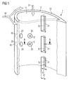
- FIG. 1 one half of an aerofoil 1 of a turbine is shown in a perspective view as seen from the inside of the aerofoil 1.
- the second half of the aerofoil 1 that would disallow the view to the inside of the aerofoil 1 is not shown is only indicated by broken and dashed lines.
- the aerofoil 1 for example a guide vane or a blade within a turbine section of a gas turbine engine, represents the turbine engine component as defined in the invention and will be present in a working fluid flow 30 during operation.
- This working fluid flow 30 is indicated as a double arrow and may be a hot gas provided by a combustion chamber located upstream.
- the aerofoil 1 has a circumferential wall 2 as a body of turbine engine component and a cavity to allow cooling fluid - a cooling fluid flow 31 is indicated via a further arrow - to cool the wall 2 from the inside and to supply cooling holes (not shown in the figure).
- the wall 2 has a first surface 10 which is exposed, in use, to the working fluid flow 30 - a hot gas path - of high temperatures.
- the first surface 10 is directed to the outside of the aerofoil 1.
- the wall 2 may be coated from the outside (not shown in Fig. 1 ; indicated in Fig. 2C ), for example by a thermal barrier coating or oxidation resistant coating, such as MCrAlY.
- the first surface 10 may also comprise the coating.
- the wall 2 has a second surface 11 which is facing away from the hot gas path and is being exposed to the cooling fluid flow 31.
- the second surface 11 is the inner wall of the aerofoil 1, surrounding the cavity.
- the second surface 11 comprises a plurality of depressions 20, 21 in different forms, e.g. a first depression 20 in form of a truncated cone, having a circular rim with the second surface 11.
- a first depression 20 in form of a truncated cone, having a circular rim with the second surface 11.
- a second depression 21 a trench is indicated having two side planes and a third bottom plane. Further types of depressions will be shown in Fig. 2 .
- the depressions 20, 21 are being exposed to the cooling fluid during operation. At the time of installation, the depressions 20, 21 are blind holes and may not supply any cooling fluid to the first surface 10.
- each of the depressions 20, 21 is oriented such that, starting from the second surface 11, the depression 20, 21 deepens in direction of a back face 12 of the first surface 10, and at the same time, a diameter of the depression 20, 21 decreases from the second surface in direction of the back face, thus resulting in a depression in form of a truncated cone (like the first depression 20), a truncated pyramid, a truncated triangular prism (like the second depression 21), or any kind of frustum, for example.
- the back face 12 will be the result of the truncation.
- the back face 12 may be substantially flat.
- a diameter may be defined as the distance between two opposing points on a wall of the depression 20, 21.
- the diameter of the depression 20, 21 decreases from the second surface 11 in direction of the back face 12, with a first diameter d1 at the second surface 11 and a second diameter d2 at the back face 12, with d1 greater than d2.
- walls of the depression 20, 21 are tilted, narrowing the diameter until the back face 12 is reached, which defines the narrowest plane with the depression 20, 21.
- a body portion 40 can be defined between the back face 12 of the first surface 10 and the first surface 10, which is part of the wall 2.
- the body portion 40 may comprise less material than other areas of the wall 2 and may define a narrow section of the wall 2. This is intentional, so that in case of oxidation of the first surface 11 of the wall 2, the wall 2 may be breached at this location and will result in a passage (see Fig. 2A and Fig. 2C , reference sign 50) for cooling air.
- Fig. 1 the aerofoil 1 is shown as manufactured. All depression 20, 21 may be blind holes which have not become passages yet.
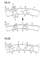
- Fig. 2A the same is shown for a short section of the wall 2 as a cross section from a direction indicated by the line A-A in Fig. 1 . Furthermore Fig. 2A also shows the appearance of the wall section once oxidation of the first surface 10 has taken place.
- a section of the wall 2 is shown, with its first surface 10 that is directed to the hot gas path.
- Hot streaming gas is indicated again via an arrow for the working fluid flow 30.
- the first depression 20 in form of a truncated cone and a second depression 21 in form of a truncated triangular prism is shown, which both appear in a cross section as truncated trapezoid or trapezium.
- the first depression 20 has an opening of the first diameter d1 then narrows until the back face 12 is reached with a diameter of the second diameter d2.
- the width of the material of the body portion 40 is indicated by the width w and may be a fraction of a width of a medium distance between the first surface 10 and the second surface 11.
- the first drawing of Fig. 2A shows the aerofoil 1 without being oxidised, for example when manufactured or if installed in an area in which no extreme temperatures occur.
- the second drawing of Fig. 2A show the aerofoil 1 after oxidisation has occurred for a longer time span.
- the first surface 10 is affected by oxidisation resulting in material loss and in an oxidised first surface 13. If the temperature remains extremely hot, the oxidisation of the oxidised first surface 11 continues, until all the material of the body portion 40 has vanished. In this case the blind holes of the depressions 20, 21 will become through holes, i.e. passages 50 which allow cooling air to pass, as indicated via arrows for cooling fluid flow 31. As a further consequence the cooling air will cool the oxidised first surface 13 in a proximity of the passage 50.
- the material degradation of the first surface 10 may continue at a slower pace. This result in further oxidisation, as indicated by a dashed line for a further oxidised first surface 14.
- the height of the passages 50 will also decrease, which has a direct impact on the width of the passage 50, due to the tilted walls of the passage 50.
- the throughput of cooling air will increase through the passage 50, because the second diameter d2 indicating the diameter of the passage exit will also increase. This has the consequence that the oxidisation of the first surface 10 will decrease further until a stable point of operation is reached, at which enough cooling air is provided via the passage 50.
- the invention provides a self adjusting principle, in which cooling passages will be created “automatically” for hot spots and the turbine engine component will adapt the diameters of the exits of the cooling passages "itself” such that the minimum needed cooling air is provided, so that no oxidisation takes place any further.
- Fig. 2B a number of depressions 22, 23, 24, 25 are shown, that are slight modifications of the first depression 20 and the second depression 21.
- Fig. 2A showed depressions 20, 21 that show a plane symmetry in regards of a plane through the centre of the back face 12, the plane being perpendicular to the first surface 10 extending perpendicular to the plane of projection. Due to the symmetry tilted walls 51 of the depression 20, 21 have the same length in the projection of Fig. 2A . Depressions with different walls 51 are shown for the depressions 22 and 24 in Fig. 2B . This allows to direct the depression in a wanted direction, so that the cooling fluid, once the passage 50 has been occurred, will be guided in a the wanted direction, for example to provide film cooling or alternatively to create turbulences.
- Depression 23 shows a specific form, in which the depression is a cone or a trapezoid without truncation.
- the back face 12 may only be a point or a line. This will result in a very small passage 50 at the beginning.
- depression 25 shows a different form, in which the walls 51 are convex.
- Other forms may be also advantageous.
- the wall 2 of the aerofoil 1 may be designed such that the oxidation mainly takes place or will be affecting the material faster on the first surface in the area of the body portion 40. This may be possible if a part of the wall 2 adjacent to the body portion 40 is of a further material that is less susceptible to erosion and/or corrosion, e.g. oxidation, than the body portion 40. This allows creating a passage 50 for cooling air even before the remainder of the first surface 10 of the wall 2 is totally oxidised.
- Fig. 2C shows an embodiment in which the complete first surface 10 is coated.
- the body portion 40 is sealing the passage 50 to become a depression in form of a blind hole merely by a coating 60.
- the principle of operation does not differ from the previously said, thus resulting in a passage 50 as shown in the second drawing of Fig. 2C .
- the solution of Fig. 2C may be advantageous in respect of manufacturing the aerofoil with its depressions, because the depression can be manufactured initially as through hole and then be closed by the coating 60.
- the aerofoil with depressions may be manufactured by casting the aerofoil including its depressions or by casting a solid aerofoil without depressions and later drilling the depressions.
- Fig. 2D shows a slightly different embodiment, in which a depression 27 is a blind hole as in Fig. 2A , with an additional coating 60 as known from Fig. 2C .
- the body portion 40 which may oxidise away, comprises a portion of the coating 60 and a portion of the wall 2 between the back face 12 and the first surface 10, as indicated in Fig. 2D .
- the part of the aerofoil 1 is shown once at the beginning of operation and in a second drawing after oxidisation has taken place and the passage 50 has been formed.
- This invention is particularly advantageous, because the operation time of turbine engine components that may be affected by oxidisation may be extended. Furthermore the invention is directed to protect installed components in a way that a slight oxidation of surfaces will be accepted. Besides, an adaption to the needed amount of cooling fluid is possible, and due to the fact that the walls of the depression are tilted, this adaption may take less time than in other implementations.
- the invention may have further advantages in respect of internal convection cooling.
- One of the benefits of a tapered depression is that it increases the internal surface area of the wall to which it is applied. This means that the depression provides some cooling benefit even before the outside part - the body portion 40 - of the depression is removed and a passage is built. If there is active impingement cooling on the inside surface, as there often is in an aerofoil, this cooling benefit could be significant. In this case, to distinguish from prior art convective cooling solutions, it may be the target to design the depression such that in a perfect installation the convective cooling may be sufficient and no erosion and/or corrosion takes place.
- the body portion 40 may be sized such that there is a chance that a passage 50 may arise during typical time of operation of the component.
- the body portion 40 may have a lesser width than known depressions that are solely intended for convection cooling.
- the convective heat transfer coefficient will also be enhanced due to turbulences of the cooling air resulting of the tapered depression.
- the depression may be arranged such that the body portion may be eroded and/or corroded completely and generating the passage 50 before a next scheduled inspection of the gas turbine in cases of continuously occurring hot spots.
- the invention allows easy manufacturing.
- the turbine engine component may be easier to cast.
- a ceramic forming the depression during the casting process is stronger with a tapered shape than with a parallel sided shape.
- a depression could start from the second surface with a cylindrical shape, later followed by a tapered portion in direction of the back face.
Landscapes
- Engineering & Computer Science (AREA)
- Mechanical Engineering (AREA)
- General Engineering & Computer Science (AREA)
- Chemical & Material Sciences (AREA)
- Materials Engineering (AREA)
- Turbine Rotor Nozzle Sealing (AREA)
Abstract
Description
- The invention relates to adaptive cooling of a hot turbine engine component, particularly a turbine aerofoil within a turbine section of a gas turbine engine.
- Components such as gas turbine blades, vanes and others in a turbine or a combustion section of a gas turbine may be affected by hot fluids resulting in oxidation of the components. This problem is addressed in several ways, e.g. by using heat resistant materials or by applying a coating, like a thermal barrier coating (TBC). Alternatively or additionally the components may be cooled. For this additional cooling, cooling air may be supplied and cooling features and cooling holes may be designed in regions to be cooled.
- Even though cooling may be necessary, the existence of cooling holes and the supply of cooling air to the region to be cooled - the cooling air may typically be taken from a compressor section of the gas turbine - may have negative side effects on the overall performance of the compressor and/or of the turbine section.
- Thus, a gas turbine may be designed such that only that amount of cooling air is provided and distributed that is considered necessary. In installed gas turbines, even if thoroughly designed, material may still oxidise during operation, e.g. due to high temperature peaks.
- According to patent application
US 2007/0036942 A1 an apparatus for adaptive cooling is disclosed comprising a first component having at least one aperture extending therethrough with a sacrificial component positioned within the at least one aperture. The first component is operable at a maximum duty temperature and the sacrificial component has a melting or sublimation point below the maximum duty temperature of the first component. The sacrificial component defines an effective aperture, the size of which may be increased if, in use, the sacrificial component is subjected to a temperature between the melting or sublimation point of the sacrificial component and the maximum duty temperature of the first component. The sacrificial component is a separate component than the first component. - A similar solution is shown in patent
US 4,136,516 , in which plugs are provided to initially close secondary air outlets. The plugs are fabricated of a material having a lower melting point temperature than that of the remainder of the blade airfoil portion such that, in the event of failure in the primary cooling system, the plugs will melt, thereby permitting the secondary coolant to rush through the blade and provide internal cooling thereof. A fairly similar technology is disclosed in patent applicationEP 1416225 A1 and patentUS 3,990,837 . - Patent
US 7,241,107 B2 shows that cooling air passages may be coated. The coating is being made of a material that has an oxidizing property such that the material oxidizes away and opens the passage to more flow when exposed to a temperature above a critical temperature of an airfoil. When the airfoil surface is not properly cooled by a flow passing through the passage, the material oxidizes away until the size of the passage increases to allow for the proper amount of cooling air to flow to cool the airfoil. The passages are through holes and each have a fixed diameter. To coat these passages may be difficult. - According to patent application
GB 2259118 A - The present invention seeks to find a solution in which the time of operation can be stretched further and downtime may be avoided even when oxidation of parts has already occurred, so that repair or replacement of parts can be performed at the next maintenance schedule and still providing a mode of operation with only marginal performance losses.
- This objective is achieved by the independent claims. The dependent claims describe advantageous developments and modifications of the invention.
- In accordance with the invention there is provided a turbine engine component, particularly an aerofoil, having a body comprising a first surface exposed to a working fluid of high temperatures during operation, so that erosion and/or corrosion, e.g. particularly oxidation, may take place on the first surface. The body is further comprising a second surface comprising at least one depression, the depression being exposed to a cooling fluid during operation, the depression being oriented such that, starting from the second surface, it deepens in direction of a back face of the first surface. A depression may be in form of a blind hole or a trench. The body also comprises a body portion between the back face and the first surface, wherein a diameter of the depression decreases from the second surface in direction of the back face. Thus, the depression can be seen as to have a particularly V-shaped cross section.
- The turbine engine component may be, besides the already mentioned aerofoils like blades or vanes in a turbine section of a gas turbine engine, a component inside a hot fluid path or a component defining and guiding the hot fluid path. This component may be located in the turbine section, in a combustor section of a gas turbine engine or any intermediate component - like a transition duct between combustor and turbine section - or downstream component - like an exhaust or a diffuser of the gas turbine engine that is downstream of the turbine section.
- More precisely, the turbine engine component may be any component within a gas turbine engine or a similar type of engine having surfaces over which hot gases are swept. Furthermore these surfaces may be part of a vane aerofoil and/or a vane platform within a turbine section, and/or a blade aerofoil and/or a blade platform and/or a blade shroud within the turbine section. The surface may also be part of a combustor. Additionally the surface may be part of a static shroud and/or a heat shield. Besides, the invention is also applicable to other hot gas swept surfaces downstream of the turbine section in a diffuser and/or in an exhaust, including heat recovery system.
- The depression may be casted or machined. If instead of a blind hole a through hole is produced during manufacturing, the through hole may be filled again partly, covered and/or plugged so that the first surface may be closed again.
- The through hole may be filled by a heat resistant material, possibly by the same material as the body, or of a material with a melting point that will permanently exceed the temperature during operation. Thus, this heat resistant material is not designed to melt during operation. But the surface directed to the hot fluid path of the heat resistant material may encounter oxidation.
- In contrast to prior art disclosure, no special coating material is needed that is merely applied to be oxidised away faster than the remainder of the first surface. Additionally, the invention is not directed to oxidise surfaces of cooling passages. It is directed to scenarios in which a hot surface that is designed to guide the hot fluid - the first surface according to the invention - may oxidise.
- The invention is advantageous, if the first surface oxidises until the body portion between the back face and the first surface gets oxidised away, so that the depression becomes a passage to the hot fluid path. Due to the fact that the depression is being exposed to the cooling fluid, this newly built passage performs the function of a cooling hole via which the cooling fluid will be guided in direction of the first surface. This results in cooling of the first surface and its surroundings in a proximity of the passage. As a consequence the oxidation may stop in that area.
- According to the invention the depression has a specific shape, so that the diameter of the depression decreases from the second surface in direction of the back face of the first surface. Once a passage has been built, this passage has an exit with a first diameter, as defined by the width of the depression, providing a first amount of cooling fluid. This will stop or slow down further oxidation in the future. Assuming, oxidation will not be prevented completely because the first amount of cooling fluid may not be sufficient to do so, the first surface including the rim of the newly built passage may oxidise further. This results in a further gradual reduction of surface material and also in enlarging the diameter of the cooling passage, due to the specific shape of the depression with its tilted walls. With the new and larger dimensions of the exit of the passage - having a second diameter -, a second amount of cooling fluid will be provided to the surroundings of the exit. The second diameter will be greater than the first diameter, the second amount of cooling fluid will exceed the first amount of cooling fluid. This principle will continue until enough cooling fluid will pass the passage so that no oxidation will occur anymore in the surroundings of the passage.
- To summarise, the inner walls of the passage itself will not oxidise but the first surface will continue to oxidise which then directly has an effect on the diameter of the exit of the passage.
- Thus, the invention advantageously provides a self adapting principle to adapt to the conditions within the hot fluid path.
- In contrast to provide a large number of cooling holes during manufacturing to accommodate the needs of worst case scenarios in regards of hot spots, the invention is advantageous because, if the heat will never reach an oxidising temperature, the depression will never become a cooling passage and therefore no performance losses will occur.
- As a consequence, uniform components may be built and installed, even though they will be impacted differently by heat due to their different locations of installation. Some of the components will operate without oxidisation and others may be affected by oxidisation.
- In an advantageous embodiment of the invention a part of the body adjacent to the body portion is of a further material that is less susceptible to erosion and/or corrosion, particularly oxidation, than the body portion. The compositions of the material may be seamlessly change so that this effect may take place. Alternatively the part of the body adjacent to the body portion may be coated.
- The last paragraph is based on the fact that one might anticipate at which positions hot spots will occur. This may not always be the case. The invention is also advantageous if the positions of hot spots will not be known beforehand or on which components the hot spots will occur. This may be the case if the locations of the hot spots depend on how the parts are assembled. In this case a plurality of depressions may be arranged in many places on several components and only these depressions will become holes eventually that are actually located at or near a hot spot.
- The body portion may also incorporate a protective coating over the first surface. Cooling holes would then be exposed after the coating and part of the component material have been lost.
- It has to be noted that embodiments of the invention have been described with reference to different subject matters. In particular, some embodiments have been described with reference to apparatus type claims whereas other embodiments have been described with reference to method type claims. However, a person skilled in the art will gather from the above and the following description that, unless other notified, in addition to any combination of features belonging to one type of subject matter also any combination between features relating to different subject matters, in particular between features of the apparatus type claims and features of the method type claims is considered as to be disclosed with this application.
- The aspects defined above and further aspects of the present invention are apparent from the examples of embodiment to be described hereinafter and are explained with reference to the examples of embodiment.
- Embodiments of the invention will now be described, by way of example only, with reference to the accompanying drawings, of which:
- FIG. 1:
- shows schematically an aerofoil with different depressions according to an embodiment of the invention;
- FIG. 2A:
- illustrates a cross section along a plane indicated by a line A-A in
Fig. 1 showing two depressions; - FIG. 2B, 2C, 2D:
- illustrate in a cross sectional view further alternative forms of depressions.
- The illustration in the drawing is schematical. It is noted that for similar or identical elements in different figures, the same reference signs will be used.
- Referring now to
FIG. 1 , one half of an aerofoil 1 of a turbine is shown in a perspective view as seen from the inside of the aerofoil 1. The second half of the aerofoil 1 that would disallow the view to the inside of the aerofoil 1 is not shown is only indicated by broken and dashed lines. - The aerofoil 1, for example a guide vane or a blade within a turbine section of a gas turbine engine, represents the turbine engine component as defined in the invention and will be present in a working
fluid flow 30 during operation. This workingfluid flow 30 is indicated as a double arrow and may be a hot gas provided by a combustion chamber located upstream. The aerofoil 1 has acircumferential wall 2 as a body of turbine engine component and a cavity to allow cooling fluid - acooling fluid flow 31 is indicated via a further arrow - to cool thewall 2 from the inside and to supply cooling holes (not shown in the figure). - The
wall 2 has afirst surface 10 which is exposed, in use, to the working fluid flow 30 - a hot gas path - of high temperatures. Thefirst surface 10 is directed to the outside of the aerofoil 1. - The
wall 2 may be coated from the outside (not shown inFig. 1 ; indicated inFig. 2C ), for example by a thermal barrier coating or oxidation resistant coating, such as MCrAlY. In this case thefirst surface 10 may also comprise the coating. - The
wall 2 has asecond surface 11 which is facing away from the hot gas path and is being exposed to the coolingfluid flow 31. For the aerofoil 1, thesecond surface 11 is the inner wall of the aerofoil 1, surrounding the cavity. - The
second surface 11 comprises a plurality ofdepressions first depression 20 in form of a truncated cone, having a circular rim with thesecond surface 11. As a second depression 21 a trench is indicated having two side planes and a third bottom plane. Further types of depressions will be shown inFig. 2 . - The
depressions depressions first surface 10. - As already indicated, each of the
depressions second surface 11, thedepression back face 12 of thefirst surface 10, and at the same time, a diameter of thedepression - The
back face 12 will be the result of the truncation. Theback face 12 may be substantially flat. - A diameter may be defined as the distance between two opposing points on a wall of the
depression depression second surface 11 in direction of theback face 12, with a first diameter d1 at thesecond surface 11 and a second diameter d2 at theback face 12, with d1 greater than d2. - As it should become clear by also consulting the figures, walls of the
depression back face 12 is reached, which defines the narrowest plane with thedepression - Furthermore a
body portion 40 can be defined between theback face 12 of thefirst surface 10 and thefirst surface 10, which is part of thewall 2. Thebody portion 40 may comprise less material than other areas of thewall 2 and may define a narrow section of thewall 2. This is intentional, so that in case of oxidation of thefirst surface 11 of thewall 2, thewall 2 may be breached at this location and will result in a passage (seeFig. 2A andFig. 2C , reference sign 50) for cooling air. - In
Fig. 1 the aerofoil 1 is shown as manufactured. Alldepression - In
Fig. 2A the same is shown for a short section of thewall 2 as a cross section from a direction indicated by the line A-A inFig. 1 . FurthermoreFig. 2A also shows the appearance of the wall section once oxidation of thefirst surface 10 has taken place. - According to
Fig. 2A , a section of thewall 2 is shown, with itsfirst surface 10 that is directed to the hot gas path. - Hot streaming gas is indicated again via an arrow for the working
fluid flow 30. In thesecond surface 11, as before, thefirst depression 20 in form of a truncated cone and asecond depression 21 in form of a truncated triangular prism is shown, which both appear in a cross section as truncated trapezoid or trapezium. - The
first depression 20 has an opening of the first diameter d1 then narrows until theback face 12 is reached with a diameter of the second diameter d2. The width of the material of thebody portion 40 is indicated by the width w and may be a fraction of a width of a medium distance between thefirst surface 10 and thesecond surface 11. - The first drawing of
Fig. 2A shows the aerofoil 1 without being oxidised, for example when manufactured or if installed in an area in which no extreme temperatures occur. - The second drawing of
Fig. 2A show the aerofoil 1 after oxidisation has occurred for a longer time span. Thefirst surface 10 is affected by oxidisation resulting in material loss and in an oxidisedfirst surface 13. If the temperature remains extremely hot, the oxidisation of the oxidisedfirst surface 11 continues, until all the material of thebody portion 40 has vanished. In this case the blind holes of thedepressions passages 50 which allow cooling air to pass, as indicated via arrows for coolingfluid flow 31. As a further consequence the cooling air will cool the oxidisedfirst surface 13 in a proximity of thepassage 50. - This will diminish the oxidisation of the already oxidised
first surface 13 and slowing down the material degradation at thefirst surface 10. - If still temperature peaks occur, the material degradation of the
first surface 10 may continue at a slower pace. This result in further oxidisation, as indicated by a dashed line for a further oxidisedfirst surface 14. As it can be seen, the height of thepassages 50 will also decrease, which has a direct impact on the width of thepassage 50, due to the tilted walls of thepassage 50. The throughput of cooling air will increase through thepassage 50, because the second diameter d2 indicating the diameter of the passage exit will also increase. This has the consequence that the oxidisation of thefirst surface 10 will decrease further until a stable point of operation is reached, at which enough cooling air is provided via thepassage 50. - Thus, the invention provides a self adjusting principle, in which cooling passages will be created "automatically" for hot spots and the turbine engine component will adapt the diameters of the exits of the cooling passages "itself" such that the minimum needed cooling air is provided, so that no oxidisation takes place any further.
- Even though this principle is explained for an aerofoil, the invention can be applied to other turbine engine components being affected by hot fluids. Dependent on the location of the turbine engine component, different types of depressions with different orientations may be advantageous. As examples, several types of depressions are shown in
Fig. 2B and2C . - In
Fig. 2B a number ofdepressions first depression 20 and thesecond depression 21. - The drawing of
Fig. 2A showeddepressions back face 12, the plane being perpendicular to thefirst surface 10 extending perpendicular to the plane of projection. Due to the symmetry tiltedwalls 51 of thedepression Fig. 2A . Depressions withdifferent walls 51 are shown for thedepressions Fig. 2B . This allows to direct the depression in a wanted direction, so that the cooling fluid, once thepassage 50 has been occurred, will be guided in a the wanted direction, for example to provide film cooling or alternatively to create turbulences. -
Depression 23 shows a specific form, in which the depression is a cone or a trapezoid without truncation. Thus, theback face 12 may only be a point or a line. This will result in a verysmall passage 50 at the beginning. - Even though up to now only flat walls of the
depressions depression 25 shows a different form, in which thewalls 51 are convex. Other forms may be also advantageous. - Not discussed so far, the
wall 2 of the aerofoil 1 may be designed such that the oxidation mainly takes place or will be affecting the material faster on the first surface in the area of thebody portion 40. This may be possible if a part of thewall 2 adjacent to thebody portion 40 is of a further material that is less susceptible to erosion and/or corrosion, e.g. oxidation, than thebody portion 40. This allows creating apassage 50 for cooling air even before the remainder of thefirst surface 10 of thewall 2 is totally oxidised. - This may also be possible, if only parts of the
first surface 10 of the aerofoil 1 will be coated by an oxidation resistant coating, leaving coating free gaps in the area of thebody portion 40. -
Fig. 2C shows an embodiment in which the completefirst surface 10 is coated. Thebody portion 40 is sealing thepassage 50 to become a depression in form of a blind hole merely by acoating 60. The principle of operation does not differ from the previously said, thus resulting in apassage 50 as shown in the second drawing ofFig. 2C . The solution ofFig. 2C may be advantageous in respect of manufacturing the aerofoil with its depressions, because the depression can be manufactured initially as through hole and then be closed by thecoating 60. - Besides this approach the aerofoil with depressions may be manufactured by casting the aerofoil including its depressions or by casting a solid aerofoil without depressions and later drilling the depressions.
-
Fig. 2D shows a slightly different embodiment, in which adepression 27 is a blind hole as inFig. 2A , with anadditional coating 60 as known fromFig. 2C . Thus, thecooling passage 50 will then be exposed after thecoating 60 and part of thewall 2 material have been lost. Thebody portion 40, which may oxidise away, comprises a portion of thecoating 60 and a portion of thewall 2 between theback face 12 and thefirst surface 10, as indicated inFig. 2D . As before, inFig. 2D the part of the aerofoil 1 is shown once at the beginning of operation and in a second drawing after oxidisation has taken place and thepassage 50 has been formed. - This invention is particularly advantageous, because the operation time of turbine engine components that may be affected by oxidisation may be extended. Furthermore the invention is directed to protect installed components in a way that a slight oxidation of surfaces will be accepted. Besides, an adaption to the needed amount of cooling fluid is possible, and due to the fact that the walls of the depression are tilted, this adaption may take less time than in other implementations.
- Not mentioned so far, the invention may have further advantages in respect of internal convection cooling. One of the benefits of a tapered depression is that it increases the internal surface area of the wall to which it is applied. This means that the depression provides some cooling benefit even before the outside part - the body portion 40 - of the depression is removed and a passage is built. If there is active impingement cooling on the inside surface, as there often is in an aerofoil, this cooling benefit could be significant. In this case, to distinguish from prior art convective cooling solutions, it may be the target to design the depression such that in a perfect installation the convective cooling may be sufficient and no erosion and/or corrosion takes place. In a real life installation, in which hot spots may arise due to assembly and/or manufacturing inaccuracies, the
body portion 40 may be sized such that there is a chance that apassage 50 may arise during typical time of operation of the component. Thus, thebody portion 40 may have a lesser width than known depressions that are solely intended for convection cooling. - Besides, the convective heat transfer coefficient will also be enhanced due to turbulences of the cooling air resulting of the tapered depression.
- In other words, the depression may be arranged such that the body portion may be eroded and/or corroded completely and generating the
passage 50 before a next scheduled inspection of the gas turbine in cases of continuously occurring hot spots. - Besides, it has to be mentioned that the invention allows easy manufacturing. Particularly due to the tapered form of the depressions, the turbine engine component may be easier to cast. A ceramic forming the depression during the casting process is stronger with a tapered shape than with a parallel sided shape.
- Even though the invention was explained for depressions with a continuous reduction in the diameter of the depression, also non-continuous forms are possible. For example a depression could start from the second surface with a cylindrical shape, later followed by a tapered portion in direction of the back face.
Claims (10)
- Turbine engine component (1), particularly an aerofoil, having a body (2) comprising:- a first surface (10) exposed to a working fluid of high temperatures during operation;- a second surface (11) comprising at least one depression (20, 21, 22, 23, 24, 25, 26), the depression (20, 21, ...) being exposed to a cooling fluid during operation, the depression (20, 21, ...) being oriented such that, starting from the second surface (11), it deepens in direction of a back face (12) of the first surface (10);- a body portion (40) between the back face (12) and the first surface (10);
wherein a diameter (d1, d2) of the depression (20, 21, ...) decreases from the second surface (11) in direction of the back face (12). - Turbine engine component (1) according to claim 1, characterised in that
the body portion (40) is of a material and/or of a width (w) between the first surface (10) and the back face (12) of the first surface (10), such that, in use and if exposed to a specific temperature, erosion and/or corrosion on the first surface (10) side of the body portion (40) will lay open a passage (50) to the depression (20, 21, ...). - Turbine engine component (1) according to claim 2, characterised in that
a part of the body (2) adjacent to the body portion (40) is of a further material that is less susceptible to erosion and/or corrosion than the body portion (40). - Turbine engine component (1) according to claim 3, characterised in that
the further material being an oxidation resistant coating (60). - Turbine engine component (1) according to any of the claims 2 to 4,
characterised in that
the laid open passage (50) provides the cooling fluid to effect cooling, particularly film cooling, of a proximity of the first surface (10). - Turbine engine component (1) according to claim 5, characterised in that
the diameter (d1, d2) of the depression (20, 21, ...) decreases from the second surface (11) in direction of the back face (12) such that, in use, continuing erosion and/or corrosion on the first surface (10) side of the body portion (40) results in widening the passage (50) to let pass a larger amount of cooling fluid. - Turbine engine component (1) according to claim 6, characterised in that
the diameter (d1, d2) of the depression (20, 21, ...) decreases from the second surface (11) in direction of the back face (12) such that, in use, continuing widening of the passage (50) due to erosion and/or corrosion provides an increasing amount of passed cooling fluid such that the temperature of a proximity of the first surface (10) is reduced to a value at which erosion and/or corrosion on the first surface (10) side of the body portion (40) terminates. - Gas turbine engine, comprising:at least one turbine engine component (1) configured according to one of the previous claims.
- Gas turbine engine according to claim 8,
characterised in that
the at least one turbine engine component (1) is comprised in:- a vane aerofoil, and/or- a vane platform, and/or- a blade aerofoil, and/or- a blade platform, and/or- a blade shroud, and/or- a transition duct between a combustor and a turbine section, and/or- a combustor, and/or- a static shroud, and/or- a heat shield, and/or- a diffuser, and/or- an exhaust. - Method for adaptive cooling a turbine engine component (1), the method comprising the steps of:- providing cooling fluid to the turbine engine component (1) having a body comprising a first surface (10) exposed to a working fluid of high temperatures during operation, a second surface (11) comprising a depression (20, 21, 22, 23, 24, 25, 26), the depression (20, 21, ...) being exposed to the cooling fluid during operation, the depression (20, 21, ...) being oriented such that, starting from the second surface (11), it deepens in direction of a back face (12) of the first surface (10), and also comprising a body portion (40) between the back face (12) and the first surface (10), wherein a diameter (d1, d2) of the depression (20, 21, ...) decreases from the second surface (11) in direction of the back face (12);- applying heat to the first surface (10) such that material of the first surface (10) is eroded and/or corroded on the first surface (10) side of the body portion (40) so that a passage (50) to the depression (20, 21, ...) will be laid open to allow the cooling fluid to pass.
Priority Applications (2)
| Application Number | Priority Date | Filing Date | Title |
|---|---|---|---|
| EP10152428.8A EP2354453B1 (en) | 2010-02-02 | 2010-02-02 | Turbine engine component for adaptive cooling |
| US13/017,350 US20110189015A1 (en) | 2010-02-02 | 2011-01-31 | turbine engine component for adaptive cooling |
Applications Claiming Priority (1)
| Application Number | Priority Date | Filing Date | Title |
|---|---|---|---|
| EP10152428.8A EP2354453B1 (en) | 2010-02-02 | 2010-02-02 | Turbine engine component for adaptive cooling |
Publications (2)
| Publication Number | Publication Date |
|---|---|
| EP2354453A1 true EP2354453A1 (en) | 2011-08-10 |
| EP2354453B1 EP2354453B1 (en) | 2018-03-28 |
Family
ID=42289328
Family Applications (1)
| Application Number | Title | Priority Date | Filing Date |
|---|---|---|---|
| EP10152428.8A Not-in-force EP2354453B1 (en) | 2010-02-02 | 2010-02-02 | Turbine engine component for adaptive cooling |
Country Status (2)
| Country | Link |
|---|---|
| US (1) | US20110189015A1 (en) |
| EP (1) | EP2354453B1 (en) |
Cited By (10)
| Publication number | Priority date | Publication date | Assignee | Title |
|---|---|---|---|---|
| EP2716867A1 (en) * | 2012-10-05 | 2014-04-09 | General Electric Company | Turbine components with adaptive cooling pathways |
| EP2857636A1 (en) * | 2013-10-01 | 2015-04-08 | Siemens Aktiengesellschaft | Enhanced cooling arrangement for a turbomachine component |
| EP2873806A1 (en) * | 2013-11-14 | 2015-05-20 | Siemens Aktiengesellschaft | A thermal barrier coating enhanced cooling arrangement for a turbomachine component |
| EP2937512A1 (en) * | 2014-04-23 | 2015-10-28 | United Technologies Corporation | Gas turbine engine component and corresponding assembly |
| EP3351729A1 (en) * | 2016-11-17 | 2018-07-25 | United Technologies Corporation | Gas turbine engine component and corresponding gas turbine engine |
| EP3409891A1 (en) * | 2017-05-31 | 2018-12-05 | General Electric Company | Components for use in a hot gas path of an industrial machine |
| EP3409890A1 (en) * | 2017-05-31 | 2018-12-05 | General Electric Company | Component for use in a hot gas path of an industrial machine |
| EP3409894A1 (en) * | 2017-05-31 | 2018-12-05 | General Electric Company | Adaptive cover for cooling pathway by additive manufacture |
| WO2019074514A1 (en) * | 2017-10-13 | 2019-04-18 | General Electric Company | Coated components having adaptive cooling openings and methods of making the same |
| US10927680B2 (en) | 2017-05-31 | 2021-02-23 | General Electric Company | Adaptive cover for cooling pathway by additive manufacture |
Families Citing this family (15)
| Publication number | Priority date | Publication date | Assignee | Title |
|---|---|---|---|---|
| US9435208B2 (en) | 2012-04-17 | 2016-09-06 | General Electric Company | Components with microchannel cooling |
| US10006367B2 (en) * | 2013-03-15 | 2018-06-26 | United Technologies Corporation | Self-opening cooling passages for a gas turbine engine |
| US9394798B2 (en) * | 2013-04-02 | 2016-07-19 | Honeywell International Inc. | Gas turbine engines with turbine airfoil cooling |
| KR101785228B1 (en) * | 2013-07-30 | 2017-10-12 | 미츠비시 히타치 파워 시스템즈 가부시키가이샤 | Moisture removal device for steam turbine and slit hole formation method |
| US9784123B2 (en) | 2014-01-10 | 2017-10-10 | Genearl Electric Company | Turbine components with bi-material adaptive cooling pathways |
| DE102014207790A1 (en) * | 2014-04-25 | 2015-10-29 | Siemens Aktiengesellschaft | Cooling fluid channel |
| US9718735B2 (en) * | 2015-02-03 | 2017-08-01 | General Electric Company | CMC turbine components and methods of forming CMC turbine components |
| US10738622B2 (en) | 2016-08-09 | 2020-08-11 | General Electric Company | Components having outer wall recesses for impingement cooling |
| US10508553B2 (en) | 2016-12-02 | 2019-12-17 | General Electric Company | Components having separable outer wall plugs for modulated film cooling |
| US20180347442A1 (en) * | 2017-05-31 | 2018-12-06 | General Electric Company | Lattice structure in cooling pathway by additive manufacture |
| KR102230700B1 (en) * | 2017-09-12 | 2021-03-23 | 한국기계연구원 | Gas turbin blade |
| JP7214831B2 (en) | 2018-07-31 | 2023-01-30 | ゼネラル・エレクトリック・カンパニイ | Components and manufacturing methods with mechanical locking mechanisms incorporating adaptive cooling |
| US11203939B2 (en) * | 2018-12-12 | 2021-12-21 | Raytheon Technologies Corporation | Airfoil platform with cooling orifices |
| US11248790B2 (en) | 2019-04-18 | 2022-02-15 | Rolls-Royce Corporation | Impingement cooling dust pocket |
| US11333037B2 (en) | 2020-02-06 | 2022-05-17 | Raytheon Technologies Corporation | Vane arc segment load path |
Citations (9)
| Publication number | Priority date | Publication date | Assignee | Title |
|---|---|---|---|---|
| US3990837A (en) | 1974-12-07 | 1976-11-09 | Rolls-Royce (1971) Limited | Combustion equipment for gas turbine engines |
| US4136516A (en) | 1977-06-03 | 1979-01-30 | General Electric Company | Gas turbine with secondary cooling means |
| EP0207799A2 (en) * | 1985-07-03 | 1987-01-07 | Westinghouse Electric Corporation | Improved coolant passage structure for rotor blades in a combustion turbine |
| GB2259118A (en) | 1991-08-24 | 1993-03-03 | Rolls Royce Plc | Aerofoil cooling |
| EP1375825A1 (en) * | 2002-06-17 | 2004-01-02 | General Electric Company | Failsafe film cooled wall |
| EP1416225A1 (en) | 2002-10-30 | 2004-05-06 | ALSTOM Technology Ltd | Emergency cooling system and plug for a thermally loaded component, as well as thermally loaded component |
| EP1655454A1 (en) * | 2004-11-09 | 2006-05-10 | General Electric Company | Coated wall with cooling arrangement |
| US20060263217A1 (en) * | 2005-05-19 | 2006-11-23 | Spanks William A Jr | Gas turbine airfoil with adjustable cooling air flow passages |
| US20070036942A1 (en) | 2005-08-11 | 2007-02-15 | Rolls-Royce Plc | Cooling method and apparatus |
Family Cites Families (5)
| Publication number | Priority date | Publication date | Assignee | Title |
|---|---|---|---|---|
| DE3615226A1 (en) * | 1986-05-06 | 1987-11-12 | Mtu Muenchen Gmbh | HOT GAS OVERHEATING PROTECTION DEVICE FOR GAS TURBINE ENGINES |
| JP2000517397A (en) * | 1996-09-04 | 2000-12-26 | シーメンス アクチエンゲゼルシヤフト | Turbine blades exposed to hot gas flow |
| EP1160352B1 (en) * | 2000-05-31 | 2009-04-22 | ALSTOM Technology Ltd | Method of adjusting the size of cooling holes of a gas turbine component |
| FR2870560B1 (en) * | 2004-05-18 | 2006-08-25 | Snecma Moteurs Sa | HIGH TEMPERATURE RATIO COOLING CIRCUIT FOR GAS TURBINE BLADE |
| US20090074576A1 (en) * | 2006-04-20 | 2009-03-19 | Florida Turbine Technologies, Inc. | Turbine blade with cooling breakout passages |
-
2010
- 2010-02-02 EP EP10152428.8A patent/EP2354453B1/en not_active Not-in-force
-
2011
- 2011-01-31 US US13/017,350 patent/US20110189015A1/en not_active Abandoned
Patent Citations (10)
| Publication number | Priority date | Publication date | Assignee | Title |
|---|---|---|---|---|
| US3990837A (en) | 1974-12-07 | 1976-11-09 | Rolls-Royce (1971) Limited | Combustion equipment for gas turbine engines |
| US4136516A (en) | 1977-06-03 | 1979-01-30 | General Electric Company | Gas turbine with secondary cooling means |
| EP0207799A2 (en) * | 1985-07-03 | 1987-01-07 | Westinghouse Electric Corporation | Improved coolant passage structure for rotor blades in a combustion turbine |
| GB2259118A (en) | 1991-08-24 | 1993-03-03 | Rolls Royce Plc | Aerofoil cooling |
| EP1375825A1 (en) * | 2002-06-17 | 2004-01-02 | General Electric Company | Failsafe film cooled wall |
| EP1416225A1 (en) | 2002-10-30 | 2004-05-06 | ALSTOM Technology Ltd | Emergency cooling system and plug for a thermally loaded component, as well as thermally loaded component |
| EP1655454A1 (en) * | 2004-11-09 | 2006-05-10 | General Electric Company | Coated wall with cooling arrangement |
| US20060263217A1 (en) * | 2005-05-19 | 2006-11-23 | Spanks William A Jr | Gas turbine airfoil with adjustable cooling air flow passages |
| US7241107B2 (en) | 2005-05-19 | 2007-07-10 | Spanks Jr William A | Gas turbine airfoil with adjustable cooling air flow passages |
| US20070036942A1 (en) | 2005-08-11 | 2007-02-15 | Rolls-Royce Plc | Cooling method and apparatus |
Cited By (22)
| Publication number | Priority date | Publication date | Assignee | Title |
|---|---|---|---|---|
| EP2716867A1 (en) * | 2012-10-05 | 2014-04-09 | General Electric Company | Turbine components with adaptive cooling pathways |
| US9617859B2 (en) | 2012-10-05 | 2017-04-11 | General Electric Company | Turbine components with passive cooling pathways |
| EP2857636A1 (en) * | 2013-10-01 | 2015-04-08 | Siemens Aktiengesellschaft | Enhanced cooling arrangement for a turbomachine component |
| EP2873806A1 (en) * | 2013-11-14 | 2015-05-20 | Siemens Aktiengesellschaft | A thermal barrier coating enhanced cooling arrangement for a turbomachine component |
| WO2015071141A1 (en) * | 2013-11-14 | 2015-05-21 | Siemens Aktiengesellschaft | A thermal barrier coating enhanced cooling arrangement for a turbomachine component |
| EP2937512A1 (en) * | 2014-04-23 | 2015-10-28 | United Technologies Corporation | Gas turbine engine component and corresponding assembly |
| US9797260B2 (en) | 2014-04-23 | 2017-10-24 | United Technologies Corporation | Engine component with wear surface protection |
| US10662779B2 (en) | 2016-11-17 | 2020-05-26 | Raytheon Technologies Corporation | Gas turbine engine component with degradation cooling scheme |
| EP3351729A1 (en) * | 2016-11-17 | 2018-07-25 | United Technologies Corporation | Gas turbine engine component and corresponding gas turbine engine |
| US10760430B2 (en) | 2017-05-31 | 2020-09-01 | General Electric Company | Adaptively opening backup cooling pathway |
| EP3409894A1 (en) * | 2017-05-31 | 2018-12-05 | General Electric Company | Adaptive cover for cooling pathway by additive manufacture |
| CN108979733A (en) * | 2017-05-31 | 2018-12-11 | 通用电气公司 | For the component in the hot gas path of industrial machine |
| CN108979731A (en) * | 2017-05-31 | 2018-12-11 | 通用电气公司 | The cooling path adaptively opened |
| JP2019011753A (en) * | 2017-05-31 | 2019-01-24 | ゼネラル・エレクトリック・カンパニイ | Cooling path opening adaptively |
| EP3409890A1 (en) * | 2017-05-31 | 2018-12-05 | General Electric Company | Component for use in a hot gas path of an industrial machine |
| US10704399B2 (en) | 2017-05-31 | 2020-07-07 | General Electric Company | Adaptively opening cooling pathway |
| EP3409891A1 (en) * | 2017-05-31 | 2018-12-05 | General Electric Company | Components for use in a hot gas path of an industrial machine |
| US10927680B2 (en) | 2017-05-31 | 2021-02-23 | General Electric Company | Adaptive cover for cooling pathway by additive manufacture |
| US11041389B2 (en) | 2017-05-31 | 2021-06-22 | General Electric Company | Adaptive cover for cooling pathway by additive manufacture |
| WO2019074514A1 (en) * | 2017-10-13 | 2019-04-18 | General Electric Company | Coated components having adaptive cooling openings and methods of making the same |
| US11352886B2 (en) | 2017-10-13 | 2022-06-07 | General Electric Company | Coated components having adaptive cooling openings and methods of making the same |
| EP3695101B1 (en) * | 2017-10-13 | 2024-11-27 | General Electric Technology GmbH | Coated components having adaptive cooling openings |
Also Published As
| Publication number | Publication date |
|---|---|
| EP2354453B1 (en) | 2018-03-28 |
| US20110189015A1 (en) | 2011-08-04 |
Similar Documents
| Publication | Publication Date | Title |
|---|---|---|
| EP2354453B1 (en) | Turbine engine component for adaptive cooling | |
| EP2860359B1 (en) | Arrangement for cooling a component in the hot gas path of a gas turbine | |
| EP2365188B1 (en) | Cooling gas turbine components with seal slot channels | |
| CN101315032B (en) | Stator-rotor assembly having surface feature for enhanced containment of gas flow and related processes | |
| EP2607624B1 (en) | Vane for a turbomachine | |
| JP4250088B2 (en) | Collision cooling structure of gas turbine rotor blade or stationary blade | |
| EP1936468A1 (en) | Bi-metallic elements for adjusting a cooling channel | |
| US20090074576A1 (en) | Turbine blade with cooling breakout passages | |
| US20100124485A1 (en) | Aerofoil cooling arrangement | |
| US20100054915A1 (en) | Airfoil insert | |
| EP3168535B1 (en) | Aerodynamically shaped body and method for cooling a body provided in a hot fluid flow | |
| JP2008075644A (en) | Airfoil bucket for turbine engine | |
| EP3406852B1 (en) | Turbine component with tip film cooling and method of cooling | |
| EP3090145B1 (en) | Gas turbine engine component cooling passage turbulator | |
| KR102715377B1 (en) | Two portion cooling passage for airfoil | |
| CN104704203B (en) | Turbo blade is arranged | |
| JP2012530870A (en) | Annular flow path for turbomachinery | |
| WO2015071141A1 (en) | A thermal barrier coating enhanced cooling arrangement for a turbomachine component | |
| CN101208497A (en) | Heat shields and turbine guide vanes for gas turbines | |
| JP2021127764A (en) | High temperature gas path components including rear end exhaust conduit and rear end flange | |
| CN104379874A (en) | A component and a method of cooling a component | |
| WO2019002274A1 (en) | A turbomachine component and method of manufacturing a turbomachine component | |
| JP6948793B2 (en) | Gas turbine blades and manufacturing method | |
| JP4202038B2 (en) | Method for selectively arranging turbine nozzle and shroud and gas turbine | |
| KR102690189B1 (en) | Method of forming cooling passage for turbine component with cap element |
Legal Events
| Date | Code | Title | Description |
|---|---|---|---|
| PUAI | Public reference made under article 153(3) epc to a published international application that has entered the european phase |
Free format text: ORIGINAL CODE: 0009012 |
|
| AK | Designated contracting states |
Kind code of ref document: A1 Designated state(s): AT BE BG CH CY CZ DE DK EE ES FI FR GB GR HR HU IE IS IT LI LT LU LV MC MK MT NL NO PL PT RO SE SI SK SM TR |
|
| 17P | Request for examination filed |
Effective date: 20120210 |
|
| RAP1 | Party data changed (applicant data changed or rights of an application transferred) |
Owner name: SIEMENS AKTIENGESELLSCHAFT |
|
| 17Q | First examination report despatched |
Effective date: 20160307 |
|
| RAP1 | Party data changed (applicant data changed or rights of an application transferred) |
Owner name: SIEMENS AKTIENGESELLSCHAFT |
|
| GRAP | Despatch of communication of intention to grant a patent |
Free format text: ORIGINAL CODE: EPIDOSNIGR1 |
|
| STAA | Information on the status of an ep patent application or granted ep patent |
Free format text: STATUS: GRANT OF PATENT IS INTENDED |
|
| INTG | Intention to grant announced |
Effective date: 20171018 |
|
| GRAS | Grant fee paid |
Free format text: ORIGINAL CODE: EPIDOSNIGR3 |
|
| GRAA | (expected) grant |
Free format text: ORIGINAL CODE: 0009210 |
|
| STAA | Information on the status of an ep patent application or granted ep patent |
Free format text: STATUS: THE PATENT HAS BEEN GRANTED |
|
| AK | Designated contracting states |
Kind code of ref document: B1 Designated state(s): AT BE BG CH CY CZ DE DK EE ES FI FR GB GR HR HU IE IS IT LI LT LU LV MC MK MT NL NO PL PT RO SE SI SK SM TR |
|
| REG | Reference to a national code |
Ref country code: GB Ref legal event code: FG4D |
|
| REG | Reference to a national code |
Ref country code: CH Ref legal event code: EP |
|
| REG | Reference to a national code |
Ref country code: AT Ref legal event code: REF Ref document number: 983638 Country of ref document: AT Kind code of ref document: T Effective date: 20180415 |
|
| REG | Reference to a national code |
Ref country code: IE Ref legal event code: FG4D |
|
| REG | Reference to a national code |
Ref country code: DE Ref legal event code: R096 Ref document number: 602010049449 Country of ref document: DE |
|
| PG25 | Lapsed in a contracting state [announced via postgrant information from national office to epo] |
Ref country code: LT Free format text: LAPSE BECAUSE OF FAILURE TO SUBMIT A TRANSLATION OF THE DESCRIPTION OR TO PAY THE FEE WITHIN THE PRESCRIBED TIME-LIMIT Effective date: 20180328 Ref country code: FI Free format text: LAPSE BECAUSE OF FAILURE TO SUBMIT A TRANSLATION OF THE DESCRIPTION OR TO PAY THE FEE WITHIN THE PRESCRIBED TIME-LIMIT Effective date: 20180328 Ref country code: HR Free format text: LAPSE BECAUSE OF FAILURE TO SUBMIT A TRANSLATION OF THE DESCRIPTION OR TO PAY THE FEE WITHIN THE PRESCRIBED TIME-LIMIT Effective date: 20180328 Ref country code: NO Free format text: LAPSE BECAUSE OF FAILURE TO SUBMIT A TRANSLATION OF THE DESCRIPTION OR TO PAY THE FEE WITHIN THE PRESCRIBED TIME-LIMIT Effective date: 20180628 |
|
| REG | Reference to a national code |
Ref country code: NL Ref legal event code: MP Effective date: 20180328 |
|
| REG | Reference to a national code |
Ref country code: LT Ref legal event code: MG4D |
|
| PG25 | Lapsed in a contracting state [announced via postgrant information from national office to epo] |
Ref country code: GR Free format text: LAPSE BECAUSE OF FAILURE TO SUBMIT A TRANSLATION OF THE DESCRIPTION OR TO PAY THE FEE WITHIN THE PRESCRIBED TIME-LIMIT Effective date: 20180629 Ref country code: BG Free format text: LAPSE BECAUSE OF FAILURE TO SUBMIT A TRANSLATION OF THE DESCRIPTION OR TO PAY THE FEE WITHIN THE PRESCRIBED TIME-LIMIT Effective date: 20180628 Ref country code: SE Free format text: LAPSE BECAUSE OF FAILURE TO SUBMIT A TRANSLATION OF THE DESCRIPTION OR TO PAY THE FEE WITHIN THE PRESCRIBED TIME-LIMIT Effective date: 20180328 Ref country code: LV Free format text: LAPSE BECAUSE OF FAILURE TO SUBMIT A TRANSLATION OF THE DESCRIPTION OR TO PAY THE FEE WITHIN THE PRESCRIBED TIME-LIMIT Effective date: 20180328 |
|
| PG25 | Lapsed in a contracting state [announced via postgrant information from national office to epo] |
Ref country code: PL Free format text: LAPSE BECAUSE OF FAILURE TO SUBMIT A TRANSLATION OF THE DESCRIPTION OR TO PAY THE FEE WITHIN THE PRESCRIBED TIME-LIMIT Effective date: 20180328 Ref country code: NL Free format text: LAPSE BECAUSE OF FAILURE TO SUBMIT A TRANSLATION OF THE DESCRIPTION OR TO PAY THE FEE WITHIN THE PRESCRIBED TIME-LIMIT Effective date: 20180328 Ref country code: EE Free format text: LAPSE BECAUSE OF FAILURE TO SUBMIT A TRANSLATION OF THE DESCRIPTION OR TO PAY THE FEE WITHIN THE PRESCRIBED TIME-LIMIT Effective date: 20180328 Ref country code: RO Free format text: LAPSE BECAUSE OF FAILURE TO SUBMIT A TRANSLATION OF THE DESCRIPTION OR TO PAY THE FEE WITHIN THE PRESCRIBED TIME-LIMIT Effective date: 20180328 Ref country code: ES Free format text: LAPSE BECAUSE OF FAILURE TO SUBMIT A TRANSLATION OF THE DESCRIPTION OR TO PAY THE FEE WITHIN THE PRESCRIBED TIME-LIMIT Effective date: 20180328 |
|
| PG25 | Lapsed in a contracting state [announced via postgrant information from national office to epo] |
Ref country code: SM Free format text: LAPSE BECAUSE OF FAILURE TO SUBMIT A TRANSLATION OF THE DESCRIPTION OR TO PAY THE FEE WITHIN THE PRESCRIBED TIME-LIMIT Effective date: 20180328 Ref country code: CZ Free format text: LAPSE BECAUSE OF FAILURE TO SUBMIT A TRANSLATION OF THE DESCRIPTION OR TO PAY THE FEE WITHIN THE PRESCRIBED TIME-LIMIT Effective date: 20180328 Ref country code: SK Free format text: LAPSE BECAUSE OF FAILURE TO SUBMIT A TRANSLATION OF THE DESCRIPTION OR TO PAY THE FEE WITHIN THE PRESCRIBED TIME-LIMIT Effective date: 20180328 |
|
| REG | Reference to a national code |
Ref country code: AT Ref legal event code: MK05 Ref document number: 983638 Country of ref document: AT Kind code of ref document: T Effective date: 20180328 |
|
| PG25 | Lapsed in a contracting state [announced via postgrant information from national office to epo] |
Ref country code: PT Free format text: LAPSE BECAUSE OF FAILURE TO SUBMIT A TRANSLATION OF THE DESCRIPTION OR TO PAY THE FEE WITHIN THE PRESCRIBED TIME-LIMIT Effective date: 20180730 |
|
| REG | Reference to a national code |
Ref country code: DE Ref legal event code: R097 Ref document number: 602010049449 Country of ref document: DE |
|
| PG25 | Lapsed in a contracting state [announced via postgrant information from national office to epo] |
Ref country code: DK Free format text: LAPSE BECAUSE OF FAILURE TO SUBMIT A TRANSLATION OF THE DESCRIPTION OR TO PAY THE FEE WITHIN THE PRESCRIBED TIME-LIMIT Effective date: 20180328 Ref country code: AT Free format text: LAPSE BECAUSE OF FAILURE TO SUBMIT A TRANSLATION OF THE DESCRIPTION OR TO PAY THE FEE WITHIN THE PRESCRIBED TIME-LIMIT Effective date: 20180328 |
|
| PLBE | No opposition filed within time limit |
Free format text: ORIGINAL CODE: 0009261 |
|
| STAA | Information on the status of an ep patent application or granted ep patent |
Free format text: STATUS: NO OPPOSITION FILED WITHIN TIME LIMIT |
|
| PG25 | Lapsed in a contracting state [announced via postgrant information from national office to epo] |
Ref country code: IT Free format text: LAPSE BECAUSE OF FAILURE TO SUBMIT A TRANSLATION OF THE DESCRIPTION OR TO PAY THE FEE WITHIN THE PRESCRIBED TIME-LIMIT Effective date: 20180328 |
|
| 26N | No opposition filed |
Effective date: 20190103 |
|
| PG25 | Lapsed in a contracting state [announced via postgrant information from national office to epo] |
Ref country code: SI Free format text: LAPSE BECAUSE OF FAILURE TO SUBMIT A TRANSLATION OF THE DESCRIPTION OR TO PAY THE FEE WITHIN THE PRESCRIBED TIME-LIMIT Effective date: 20180328 |
|
| REG | Reference to a national code |
Ref country code: CH Ref legal event code: PL |
|
| PG25 | Lapsed in a contracting state [announced via postgrant information from national office to epo] |
Ref country code: LU Free format text: LAPSE BECAUSE OF NON-PAYMENT OF DUE FEES Effective date: 20190202 Ref country code: MC Free format text: LAPSE BECAUSE OF FAILURE TO SUBMIT A TRANSLATION OF THE DESCRIPTION OR TO PAY THE FEE WITHIN THE PRESCRIBED TIME-LIMIT Effective date: 20180328 |
|
| REG | Reference to a national code |
Ref country code: BE Ref legal event code: MM Effective date: 20190228 |
|
| REG | Reference to a national code |
Ref country code: IE Ref legal event code: MM4A |
|
| PG25 | Lapsed in a contracting state [announced via postgrant information from national office to epo] |
Ref country code: LI Free format text: LAPSE BECAUSE OF NON-PAYMENT OF DUE FEES Effective date: 20190228 Ref country code: CH Free format text: LAPSE BECAUSE OF NON-PAYMENT OF DUE FEES Effective date: 20190228 |
|
| PG25 | Lapsed in a contracting state [announced via postgrant information from national office to epo] |
Ref country code: IE Free format text: LAPSE BECAUSE OF NON-PAYMENT OF DUE FEES Effective date: 20190202 |
|
| PG25 | Lapsed in a contracting state [announced via postgrant information from national office to epo] |
Ref country code: BE Free format text: LAPSE BECAUSE OF NON-PAYMENT OF DUE FEES Effective date: 20190228 |
|
| PG25 | Lapsed in a contracting state [announced via postgrant information from national office to epo] |
Ref country code: TR Free format text: LAPSE BECAUSE OF FAILURE TO SUBMIT A TRANSLATION OF THE DESCRIPTION OR TO PAY THE FEE WITHIN THE PRESCRIBED TIME-LIMIT Effective date: 20180328 |
|
| PG25 | Lapsed in a contracting state [announced via postgrant information from national office to epo] |
Ref country code: MT Free format text: LAPSE BECAUSE OF NON-PAYMENT OF DUE FEES Effective date: 20190202 |
|
| PGFP | Annual fee paid to national office [announced via postgrant information from national office to epo] |
Ref country code: DE Payment date: 20200420 Year of fee payment: 11 |
|
| REG | Reference to a national code |
Ref country code: DE Ref legal event code: R081 Ref document number: 602010049449 Country of ref document: DE Owner name: SIEMENS ENERGY GLOBAL GMBH & CO. KG, DE Free format text: FORMER OWNER: SIEMENS AKTIENGESELLSCHAFT, 80333 MUENCHEN, DE |
|
| PGFP | Annual fee paid to national office [announced via postgrant information from national office to epo] |
Ref country code: FR Payment date: 20210215 Year of fee payment: 12 |
|
| PG25 | Lapsed in a contracting state [announced via postgrant information from national office to epo] |
Ref country code: CY Free format text: LAPSE BECAUSE OF FAILURE TO SUBMIT A TRANSLATION OF THE DESCRIPTION OR TO PAY THE FEE WITHIN THE PRESCRIBED TIME-LIMIT Effective date: 20180328 |
|
| PGFP | Annual fee paid to national office [announced via postgrant information from national office to epo] |
Ref country code: GB Payment date: 20210302 Year of fee payment: 12 |
|
| PG25 | Lapsed in a contracting state [announced via postgrant information from national office to epo] |
Ref country code: IS Free format text: LAPSE BECAUSE OF FAILURE TO SUBMIT A TRANSLATION OF THE DESCRIPTION OR TO PAY THE FEE WITHIN THE PRESCRIBED TIME-LIMIT Effective date: 20180728 |
|
| PG25 | Lapsed in a contracting state [announced via postgrant information from national office to epo] |
Ref country code: HU Free format text: LAPSE BECAUSE OF FAILURE TO SUBMIT A TRANSLATION OF THE DESCRIPTION OR TO PAY THE FEE WITHIN THE PRESCRIBED TIME-LIMIT; INVALID AB INITIO Effective date: 20100202 |
|
| REG | Reference to a national code |
Ref country code: DE Ref legal event code: R119 Ref document number: 602010049449 Country of ref document: DE |
|
| PG25 | Lapsed in a contracting state [announced via postgrant information from national office to epo] |
Ref country code: DE Free format text: LAPSE BECAUSE OF NON-PAYMENT OF DUE FEES Effective date: 20210901 |
|
| PG25 | Lapsed in a contracting state [announced via postgrant information from national office to epo] |
Ref country code: MK Free format text: LAPSE BECAUSE OF FAILURE TO SUBMIT A TRANSLATION OF THE DESCRIPTION OR TO PAY THE FEE WITHIN THE PRESCRIBED TIME-LIMIT Effective date: 20180328 |
|
| GBPC | Gb: european patent ceased through non-payment of renewal fee |
Effective date: 20220202 |
|
| PG25 | Lapsed in a contracting state [announced via postgrant information from national office to epo] |
Ref country code: FR Free format text: LAPSE BECAUSE OF NON-PAYMENT OF DUE FEES Effective date: 20220228 |
|
| PG25 | Lapsed in a contracting state [announced via postgrant information from national office to epo] |
Ref country code: GB Free format text: LAPSE BECAUSE OF NON-PAYMENT OF DUE FEES Effective date: 20220202 |