EP2354370A1 - Device for connecting building boards - Google Patents
Device for connecting building boards Download PDFInfo
- Publication number
- EP2354370A1 EP2354370A1 EP11151968A EP11151968A EP2354370A1 EP 2354370 A1 EP2354370 A1 EP 2354370A1 EP 11151968 A EP11151968 A EP 11151968A EP 11151968 A EP11151968 A EP 11151968A EP 2354370 A1 EP2354370 A1 EP 2354370A1
- Authority
- EP
- European Patent Office
- Prior art keywords
- boards
- top plate
- spring leaf
- board
- planar flange
- Prior art date
- Legal status (The legal status is an assumption and is not a legal conclusion. Google has not performed a legal analysis and makes no representation as to the accuracy of the status listed.)
- Granted
Links
Images


Classifications
-
- E—FIXED CONSTRUCTIONS
- E04—BUILDING
- E04F—FINISHING WORK ON BUILDINGS, e.g. STAIRS, FLOORS
- E04F15/00—Flooring
- E04F15/02—Flooring or floor layers composed of a number of similar elements
- E04F15/04—Flooring or floor layers composed of a number of similar elements only of wood or with a top layer of wood, e.g. with wooden or metal connecting members
-
- E—FIXED CONSTRUCTIONS
- E04—BUILDING
- E04F—FINISHING WORK ON BUILDINGS, e.g. STAIRS, FLOORS
- E04F15/00—Flooring
- E04F15/02—Flooring or floor layers composed of a number of similar elements
- E04F15/10—Flooring or floor layers composed of a number of similar elements of other materials, e.g. fibrous or chipped materials, organic plastics, magnesite tiles, hardboard, or with a top layer of other materials
-
- E—FIXED CONSTRUCTIONS
- E04—BUILDING
- E04F—FINISHING WORK ON BUILDINGS, e.g. STAIRS, FLOORS
- E04F15/00—Flooring
- E04F15/02—Flooring or floor layers composed of a number of similar elements
- E04F15/02044—Separate elements for fastening to an underlayer
- E04F2015/0205—Separate elements for fastening to an underlayer with load-supporting elongated furring elements between the flooring elements and the underlayer
- E04F2015/02066—Separate elements for fastening to an underlayer with load-supporting elongated furring elements between the flooring elements and the underlayer with additional fastening elements between furring elements and flooring elements
- E04F2015/02077—Separate elements for fastening to an underlayer with load-supporting elongated furring elements between the flooring elements and the underlayer with additional fastening elements between furring elements and flooring elements the additional fastening elements located in-between two adjacent flooring elements
- E04F2015/02094—Engaging side grooves running along the whole length of the flooring elements
Definitions
- the invention relates to a device for connecting building boards.
- Conventional building boards and in particular deck boards as described e.g. in W02008/105012 typically include horizontal floors raised above the ground and supported by an underlying structure. Deck boards are generally placed side by side during construction of a deck, on top of a supporting structure such as joists. Other structures utilizing similar flooring techniques include boat docks, ramps, stairs, landings, bridges, platforms and for structures for surrounding or enclosing swimming pools and hot tubs.
- decks are constructed to withstand exposure to the elements and are often constructed from pressure treated wood, plastic or, more recently, wood fiber filled plastics also referred to as Wood Plastic Composites (WPC) and in particular PVC.
- WPC Wood Plastic Composites
- the substructure is typically formed of commonly available pressure treated lumber or alumina profiles.
- the substructure is formed with joists and headers optionally attached to posts.
- the deck boards are typically fixed transversely across the joists to the substructure, in a generally parallel relationship, by way of nails or screws, driven through the upper surface of the deck board into the joist below.
- a device for connecting building boards was described in US20050063771 that comprises an at least partially flat top plate, including a first planar flange and a second planar flange. Each of said planar flanges extends outward in a substantially horizontal plane. These planar flanges fit into slots provided into the sides of adjacent deck boards.
- Generally several of these devices are used to connect two building boards, whereby the devices typically are positioned above the underlying joist.
- At least one bottom tab extends downwardly from a bottom surface of the top plate. Bottom tabs typically rest upon the upper surface of the underlying joist.
- the known device for connecting building boards further comprises at least one spring leaf. A first end of the spring leaf is connected to said bottom tab. The at least one spring leaf of said device provides for expansion and contraction of the boards after installation, and in particular, provides for post-installation expansion of adjoining deck boards.
- the object of the invention is to provide a device for connecting building boards of the above type and which is so simple to mount that unskilled person can carry out the mounting.
- this object is reached in that a second end of the spring leaf is connected with the top plate (6) by a breakable jam (3).
- the breakable jam breaks when the boards expand due to water absorption or temperature rise and that does not break under forces practiced during installation of building boards.
- the provision of a breakable jam at the second end of the spring leaf, connected with the top plate allows an unskilled person to install building boards equally spaced just by pressing a second building against a number of devices according to the invention that are placed in a slot provided in the side of an adjacent first building board.
- a breakable jam is understood to be a connection between the second end of a spring leaf and the top plate that does not break under a force practiced during installing of building boards, but that breaks when the boards expand due to water absorption or temperature rise.
- a skilled person may easily determine the dimensions of the connection between the second end of the spring leaf and the top plate that allow equally spaced installation of building board without breaking the jam and that still allow breaking of the jam under forces caused by expansion of the boards.
- the spring leaf becomes a spring element only when the jam is broken.
- the breakable jam at the second end of the spring breaks when the boards expand due to water absorption or temperature rise. This allows the boards to expand, whereby the spacing between adjacent the boards is controlled by the springs such that all the spacing between the boards remain equal, or become again equal when all breakable jams are broken by the expansion of the boards.
- a further advantage of the device according to the invention is that building boards can expand and shrink freely in their length direction as well and that an easy replacement of a single board is possible.
- the breakable jam is connected with the top plate. This feature allows an easy control of the force required to break the jam. Elements that collapse under expansion due to swelling of wood are known from US20040182034 . However once collapsed, they loose their spring function, which causes loose lying building boards with different spacing in between. An advantage of the breakable jam of the invention is that once broken, the spring leafs remain a guarantee for equally spaced building boards.
- the bottom plate further comprises a fastener for connecting the device to a support member.
- the fastener comprises a fastening aperture. This allows an easy connection of the device according to the invention to the underling joist.
- the fastener for comprises spring clips.
- the spring clips allow an easy connection with an underlying joist comprising mounting tabs.
- the invention further relates to a kit of parts comprising a device according to the invention a building board comprising a slot to receive a planar flange of the device.
- a building board is a wood fiber filled PVC deck board.
- the invention also relates to a kit of parts according to the invention, further comprising a support joist with mounting tabs to receive the spring clips.
- Figure 1 shows a bottom up view device according to the invention (1), comprising an at least partially flat top plate (6), including a first planar flange (5) and a second planar flange (5), each of said planar flanges extending outward in a substantially horizontal plane, a bottom tab (4) extending downwardly from a bottom surface of said top plate (6) and two spring leafs (2), the first ends of the spring leafs are connected to said tab (4) and the second ends of the spring leafs are connected to the top plate (6) via breakable jams (3).
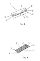
- Figure 2 shows top down view of the device according to the invention (1), comprising an at least partially flat top plate (6), including a first planar flange (5) and a second planar flange (5), each of said planar flanges extending outward in a substantially horizontal plane, a bottom tab (4) extending downwardly from the bottom surface of said top plate (6) and two spring leafs (2).
- One of the spring leafs is visibly connected with a breakable jam (3) to the top plate (6).
- Figure 3 shows a bottom up view of a further embodiment of the device according to the invention (1), comprising an at least partially flat top plate (6), including a first planar flange (5) and a second planar flange (5), each of said planar flanges extending outward in a substantially horizontal plane, a bottom tab (4) extending downwardly from a bottom surface of said top plate (6) and two spring leafs (2), the first ends of the spring leafs are connected to said tab (4) and the second ends of the spring leafs have breakable jams (3) connected to the top plate (6), one of which is not visible in Fig.3 .
- Figure 4 shows top down view of the device according to the invention (1), comprising a flat top plate (6), including a first planar flange (5) and a second planar flange (5), each of said planar flanges extending outward in a substantially horizontal plane, a bottom tab (not visible) extending downwardly from the bottom surface of said top plate (6) and two spring leafs (2).
- the spring leafs are visibly connected with a breakable jam (3, only one shown) to the top plate (6).
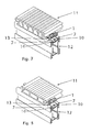
- Fig. 5 shows a top view of the first embodiment of the invention (1) wherein the bottom surface is provided with a fastener (8) for connecting the device to a supporting joist (not shown).
- the fastener further comprises a fastening aperture (9) and four spring clips (10).
- Fig. 6 shows a top view of a second embodiment of the invention including wherein the bottom surface is provided with a fastener (8) for connecting the device to a supporting joist (not shown).
- the fastener further comprises a fastening aperture (9) and four spring clips (10), to connect the devise according to the invention to the supporting joist.
- Fig. 7 shows a perspective view of a deck board (11), connected via a first device according to the invention (1) to a support joist (12).
- a support joist (12) One planar flange fits into a slot (13) provided into the side of the deck board (11).
- Two spring clips (10) are shown, which connects the fastener to mounting tabs (7) of the support joist (12).
- Fig. 8 shows a perspective view of a deck board (11), connected via a second device according to the invention (1) to a support joist (12).
- a support joist (12) One planar flange fits into a slot (13) provided into the side of the deck board (11).
- Two spring clips (10) are shown, which connects the fastener to mounting tabs (7) of the support joist (12).
Landscapes
- Engineering & Computer Science (AREA)
- Architecture (AREA)
- Civil Engineering (AREA)
- Structural Engineering (AREA)
- Life Sciences & Earth Sciences (AREA)
- Wood Science & Technology (AREA)
- Floor Finish (AREA)
- Joining Of Building Structures In Genera (AREA)
- Finishing Walls (AREA)
Abstract
Description
- The invention relates to a device for connecting building boards.
- Conventional building boards and in particular deck boards as described e.g. in
W02008/105012 typically include horizontal floors raised above the ground and supported by an underlying structure. Deck boards are generally placed side by side during construction of a deck, on top of a supporting structure such as joists. Other structures utilizing similar flooring techniques include boat docks, ramps, stairs, landings, bridges, platforms and for structures for surrounding or enclosing swimming pools and hot tubs. - Typically, decks are constructed to withstand exposure to the elements and are often constructed from pressure treated wood, plastic or, more recently, wood fiber filled plastics also referred to as Wood Plastic Composites (WPC) and in particular PVC. Whether the deck boards, which form the flooring of the deck, are comprised of wood or plastic or other material, the substructure is typically formed of commonly available pressure treated lumber or alumina profiles. The substructure is formed with joists and headers optionally attached to posts. The deck boards are typically fixed transversely across the joists to the substructure, in a generally parallel relationship, by way of nails or screws, driven through the upper surface of the deck board into the joist below.
- This manner of attaching deck boards to the substructure presents several disadvantages. If nails or screws are used, they typically cause discoloration of the surrounding wood surface over time. In addition, in driving the nail through the wood or plastic deck board, the surface of the board is often marred during hammering, causing unsightly dents and scratches to the top surface of the board. Both the discoloration of the wood and marring of the surface are of particular concern when exotic hardwoods are used.
- In addition, nails have a tendency to work themselves loose from the board over time, projecting upward from the board's surface. Not only is this aesthetically unpleasing, it causes the deck board to loosen against the joist and also constitutes a safety hazard, particularly to individuals walking over the deck surface barefoot. In addition, both nails and screws are prone to rusting over time, causing failure to the attachment. Removal of one or more deck boards entails prying the nails loose, which is both time consuming and causes damage to the surface of the board.
- Since decks are constantly exposed to outside environmental conditions, the deck boards are exposed to extremes of both temperature and humidity. Both plastic and wooden deck boards will shrink and expand in response to temperature changes, and wooden deck boards will also shrink and expand as the moisture content of the board increases or decreases. Deficiencies in the attachment means in the prior art often cause attachment devices to loosen over time or to cause the deck boards to warp or crack because the attachment device does not provide for movement along with the board as it expands or contracts.
- To avoid the difficulties presented by attachment devices as described above, a device for connecting building boards was described in
US20050063771 that comprises an at least partially flat top plate, including a first planar flange and a second planar flange. Each of said planar flanges extends outward in a substantially horizontal plane. These planar flanges fit into slots provided into the sides of adjacent deck boards. Generally several of these devices are used to connect two building boards, whereby the devices typically are positioned above the underlying joist. At least one bottom tab extends downwardly from a bottom surface of the top plate. Bottom tabs typically rest upon the upper surface of the underlying joist. The known device for connecting building boards further comprises at least one spring leaf. A first end of the spring leaf is connected to said bottom tab. The at least one spring leaf of said device provides for expansion and contraction of the boards after installation, and in particular, provides for post-installation expansion of adjoining deck boards. - However, after mounting of the building boards, the building boards should be equally spaced. This requires that during mounting all boards should be subjected to equal forces to equally compress the leaf springs of all the devices used to connect two adjacent building boards. This is difficult and requires skilled persons.
- The object of the invention is to provide a device for connecting building boards of the above type and which is so simple to mount that unskilled person can carry out the mounting.
- According to the invention this object is reached in that a second end of the spring leaf is connected with the top plate (6) by a breakable jam (3). The breakable jam breaks when the boards expand due to water absorption or temperature rise and that does not break under forces practiced during installation of building boards. The provision of a breakable jam at the second end of the spring leaf, connected with the top plate, allows an unskilled person to install building boards equally spaced just by pressing a second building against a number of devices according to the invention that are placed in a slot provided in the side of an adjacent first building board.
- A breakable jam is understood to be a connection between the second end of a spring leaf and the top plate that does not break under a force practiced during installing of building boards, but that breaks when the boards expand due to water absorption or temperature rise. Depending on the material of the device of the invention, a skilled person may easily determine the dimensions of the connection between the second end of the spring leaf and the top plate that allow equally spaced installation of building board without breaking the jam and that still allow breaking of the jam under forces caused by expansion of the boards. The spring leaf becomes a spring element only when the jam is broken.
- The breakable jam at the second end of the spring breaks when the boards expand due to water absorption or temperature rise. This allows the boards to expand, whereby the spacing between adjacent the boards is controlled by the springs such that all the spacing between the boards remain equal, or become again equal when all breakable jams are broken by the expansion of the boards.
- A further advantage of the device according to the invention is that building boards can expand and shrink freely in their length direction as well and that an easy replacement of a single board is possible.
- According to the invention, the breakable jam is connected with the top plate. This feature allows an easy control of the force required to break the jam. Elements that collapse under expansion due to swelling of wood are known from
US20040182034 . However once collapsed, they loose their spring function, which causes loose lying building boards with different spacing in between. An advantage of the breakable jam of the invention is that once broken, the spring leafs remain a guarantee for equally spaced building boards. - In another embodiment, at least a part of the bottom plate further comprises a fastener for connecting the device to a support member. Preferably the fastener comprises a fastening aperture. This allows an easy connection of the device according to the invention to the underling joist.
- In another preferred embodiment, the fastener for comprises spring clips. The spring clips allow an easy connection with an underlying joist comprising mounting tabs.
- The invention further relates to a kit of parts comprising a device according to the invention a building board comprising a slot to receive a planar flange of the device. Preferably the building board is a wood fiber filled PVC deck board.
- The invention also relates to a kit of parts according to the invention, further comprising a support joist with mounting tabs to receive the spring clips.
- The invention will now be explained in greater detail by means of the enclosed drawings, wherein the drawings depict:
-
Figure 1 : A perspective bottom up view of a first embodiment of a device according to the invention; -
Figure 2 : A perspective top down view of the first embodiment of the device according to the invention; -
Figure 3 : A perspective bottom up view of a second embodiment of the device according to the invention -
Figure 4 : A perspective top down view of the second embodiment of the device according to the invention; -
Fig. 5 : Top view of the first embodiment of the invention including a fastener for connecting the device to a support member. -
Fig. 6 : Top view of a second embodiment of the invention including a fastener for connecting the device to a support member. -
Fig. 7 : Perspective view showing deck board, a first device according to the invention and underlying joist. -
Fig. 8 : Perspective view showing deck board, a second device according to the invention and underlying joist. -
Figure 1 shows a bottom up view device according to the invention (1), comprising an at least partially flat top plate (6), including a first planar flange (5) and a second planar flange (5), each of said planar flanges extending outward in a substantially horizontal plane, a bottom tab (4) extending downwardly from a bottom surface of said top plate (6) and two spring leafs (2), the first ends of the spring leafs are connected to said tab (4) and the second ends of the spring leafs are connected to the top plate (6) via breakable jams (3). -
Figure 2 shows top down view of the device according to the invention (1), comprising an at least partially flat top plate (6), including a first planar flange (5) and a second planar flange (5), each of said planar flanges extending outward in a substantially horizontal plane, a bottom tab (4) extending downwardly from the bottom surface of said top plate (6) and two spring leafs (2). One of the spring leafs is visibly connected with a breakable jam (3) to the top plate (6). -
Figure 3 shows a bottom up view of a further embodiment of the device according to the invention (1), comprising an at least partially flat top plate (6), including a first planar flange (5) and a second planar flange (5), each of said planar flanges extending outward in a substantially horizontal plane, a bottom tab (4) extending downwardly from a bottom surface of said top plate (6) and two spring leafs (2), the first ends of the spring leafs are connected to said tab (4) and the second ends of the spring leafs have breakable jams (3) connected to the top plate (6), one of which is not visible inFig.3 . -
Figure 4 shows top down view of the device according to the invention (1), comprising a flat top plate (6), including a first planar flange (5) and a second planar flange (5), each of said planar flanges extending outward in a substantially horizontal plane, a bottom tab (not visible) extending downwardly from the bottom surface of said top plate (6) and two spring leafs (2). The spring leafs are visibly connected with a breakable jam (3, only one shown) to the top plate (6). -
Fig. 5 shows a top view of the first embodiment of the invention (1) wherein the bottom surface is provided with a fastener (8) for connecting the device to a supporting joist (not shown). The fastener further comprises a fastening aperture (9) and four spring clips (10). -
Fig. 6 shows a top view of a second embodiment of the invention including wherein the bottom surface is provided with a fastener (8) for connecting the device to a supporting joist (not shown). The fastener further comprises a fastening aperture (9) and four spring clips (10), to connect the devise according to the invention to the supporting joist. -
Fig. 7 shows a perspective view of a deck board (11), connected via a first device according to the invention (1) to a support joist (12). One planar flange fits into a slot (13) provided into the side of the deck board (11). Two spring clips (10) are shown, which connects the fastener to mounting tabs (7) of the support joist (12). -
Fig. 8 shows a perspective view of a deck board (11), connected via a second device according to the invention (1) to a support joist (12). One planar flange fits into a slot (13) provided into the side of the deck board (11). Two spring clips (10) are shown, which connects the fastener to mounting tabs (7) of the support joist (12).
Claims (7)
- A device for connecting building boards (1) comprising an at least partially flat top plate (6), including a first planar flange (5) and a second planar flange, each of said planar flanges extending outward in a substantially horizontal plane, at least one bottom tab (4) extending downwardly from a bottom surface of said top plate (6) and at least one spring leaf (2), a first end of the spring leaf is connected to said tab (4), characterized in that a second end of the spring leaf is connected with the top plate (6) by a breakable jam (3) that breaks when the boards expand due to water absorption or temperature rise and that does not break under forces practiced during installation of building boards.
- A device according to claim 1 or 2, wherein at least a part of the bottom plate further comprises a fastener (8) for connecting the device to a support member.
- A device according to claim 3, wherein the fastener comprises a fastening aperture (9).
- A device according to claim 1 or 2, wherein the fastener comprises spring clips (10).
- Kit of parts comprising a device according to any of the preceding claims and a building board comprising a slot (13) to receive a planar flange of the device.
- Kit of parts according to claim 6, wherein the building board is a Wood Plastic Composite, preferably a wood fiber filled PVC deck board.
- Kit of parts according to claim 6 or 7, further comprising a support joist (12) with mounting tabs (7) to receive the spring clips (10).
Priority Applications (2)
| Application Number | Priority Date | Filing Date | Title |
|---|---|---|---|
| PL11151968T PL2354370T3 (en) | 2010-01-26 | 2011-01-25 | Device for connecting building boards |
| EP11151968A EP2354370B1 (en) | 2010-01-26 | 2011-01-25 | Device for connecting building boards |
Applications Claiming Priority (2)
| Application Number | Priority Date | Filing Date | Title |
|---|---|---|---|
| EP10151693A EP2354369A1 (en) | 2010-01-26 | 2010-01-26 | Device for connecting building boards |
| EP11151968A EP2354370B1 (en) | 2010-01-26 | 2011-01-25 | Device for connecting building boards |
Publications (2)
| Publication Number | Publication Date |
|---|---|
| EP2354370A1 true EP2354370A1 (en) | 2011-08-10 |
| EP2354370B1 EP2354370B1 (en) | 2013-03-13 |
Family
ID=42272239
Family Applications (2)
| Application Number | Title | Priority Date | Filing Date |
|---|---|---|---|
| EP10151693A Withdrawn EP2354369A1 (en) | 2010-01-26 | 2010-01-26 | Device for connecting building boards |
| EP11151968A Active EP2354370B1 (en) | 2010-01-26 | 2011-01-25 | Device for connecting building boards |
Family Applications Before (1)
| Application Number | Title | Priority Date | Filing Date |
|---|---|---|---|
| EP10151693A Withdrawn EP2354369A1 (en) | 2010-01-26 | 2010-01-26 | Device for connecting building boards |
Country Status (5)
| Country | Link |
|---|---|
| EP (2) | EP2354369A1 (en) |
| ES (1) | ES2409056T3 (en) |
| HR (1) | HRP20130439T1 (en) |
| PL (1) | PL2354370T3 (en) |
| PT (1) | PT2354370E (en) |
Cited By (1)
| Publication number | Priority date | Publication date | Assignee | Title |
|---|---|---|---|---|
| CN106752049A (en) * | 2016-12-19 | 2017-05-31 | 山东霞光实业有限公司 | Novel antibacterial wood-plastic board and preparation method thereof |
Families Citing this family (3)
| Publication number | Priority date | Publication date | Assignee | Title |
|---|---|---|---|---|
| FR3002257B1 (en) * | 2013-02-15 | 2015-06-26 | Oceplast | FLAP ASSEMBLY OF THE POSITIONABLE TYPE ON A SUPPORT PLAN, FASTENER PART IMPLEMENTED IN SAID ASSEMBLY, COATING COMPRISING AT LEAST SUCH ASSEMBLY AND METHOD FOR FIXING SUCH ASSEMBLY TO A SUPPORT PLAN |
| GB2566521A (en) * | 2017-09-15 | 2019-03-20 | John Jarmey Michael | Tiling system |
| CN113272507B (en) | 2019-01-08 | 2023-03-10 | 瓦林格创新股份有限公司 | Deck system provided with a connection system and associated connection means |
Citations (3)
| Publication number | Priority date | Publication date | Assignee | Title |
|---|---|---|---|---|
| US20040182034A1 (en) | 2003-03-20 | 2004-09-23 | Eberle Harry W. | Expansion-compensating deck fastener |
| US20050063771A1 (en) | 2003-09-23 | 2005-03-24 | Harris G. Steven | Resilient deck board fastener |
| WO2008105012A1 (en) | 2007-03-01 | 2008-09-04 | Eterno Ivica Srl | Supporting system for raised floors |
-
2010
- 2010-01-26 EP EP10151693A patent/EP2354369A1/en not_active Withdrawn
-
2011
- 2011-01-25 PL PL11151968T patent/PL2354370T3/en unknown
- 2011-01-25 ES ES11151968T patent/ES2409056T3/en active Active
- 2011-01-25 EP EP11151968A patent/EP2354370B1/en active Active
- 2011-01-25 PT PT111519682T patent/PT2354370E/en unknown
-
2013
- 2013-05-20 HR HRP20130439AT patent/HRP20130439T1/en unknown
Patent Citations (3)
| Publication number | Priority date | Publication date | Assignee | Title |
|---|---|---|---|---|
| US20040182034A1 (en) | 2003-03-20 | 2004-09-23 | Eberle Harry W. | Expansion-compensating deck fastener |
| US20050063771A1 (en) | 2003-09-23 | 2005-03-24 | Harris G. Steven | Resilient deck board fastener |
| WO2008105012A1 (en) | 2007-03-01 | 2008-09-04 | Eterno Ivica Srl | Supporting system for raised floors |
Cited By (1)
| Publication number | Priority date | Publication date | Assignee | Title |
|---|---|---|---|---|
| CN106752049A (en) * | 2016-12-19 | 2017-05-31 | 山东霞光实业有限公司 | Novel antibacterial wood-plastic board and preparation method thereof |
Also Published As
| Publication number | Publication date |
|---|---|
| EP2354369A1 (en) | 2011-08-10 |
| HRP20130439T1 (en) | 2013-06-30 |
| EP2354370B1 (en) | 2013-03-13 |
| ES2409056T3 (en) | 2013-06-24 |
| PL2354370T3 (en) | 2013-07-31 |
| PT2354370E (en) | 2013-05-27 |
Similar Documents
| Publication | Publication Date | Title |
|---|---|---|
| US7052200B2 (en) | Resilient deck board fastener | |
| US6810633B2 (en) | Deck board fastener | |
| US6226947B1 (en) | Cladding board mounting system | |
| US9038324B2 (en) | Field paver connector and restraining system | |
| CA2361427C (en) | Deck system | |
| US20090217495A1 (en) | Hidden deck fastener | |
| US9790690B2 (en) | Peripheral stabilizing system for elevated flooring surface | |
| US8359794B2 (en) | Extruded plastic members for covering wood surfaces | |
| US8302360B2 (en) | Wooden roof truss | |
| EP2354370B1 (en) | Device for connecting building boards | |
| KR101790130B1 (en) | Convenient construction and maintenance-friendly deck structure | |
| KR101176363B1 (en) | Device for connecting deck | |
| US20070090232A1 (en) | Barricade system and barricade bracket for use therein | |
| US9303402B2 (en) | Basement wall and floor assembly | |
| US11085193B2 (en) | Peripheral restraint system for elevated flooring surface | |
| KR102822110B1 (en) | Anchor platform assembly with angled base plate | |
| CN111295489A (en) | deck plate | |
| US20080190069A1 (en) | Hidden Deck Fastener | |
| US5664381A (en) | Construction nailing method and structures | |
| KR20170042994A (en) | Hybrid fixing apparatus for wood deck and plate | |
| AU722347C (en) | An improved cladding board mounting system | |
| US20160369503A1 (en) | Modular flooring substrate system and element | |
| AU729806B2 (en) | An improved cladding board mounting system | |
| AU722347B2 (en) | An improved cladding board mounting system | |
| CA2894347A1 (en) | Modular flooring substrate system and element |
Legal Events
| Date | Code | Title | Description |
|---|---|---|---|
| PUAI | Public reference made under article 153(3) epc to a published international application that has entered the european phase |
Free format text: ORIGINAL CODE: 0009012 |
|
| AK | Designated contracting states |
Kind code of ref document: A1 Designated state(s): AL AT BE BG CH CY CZ DE DK EE ES FI FR GB GR HR HU IE IS IT LI LT LU LV MC MK MT NL NO PL PT RO RS SE SI SK SM TR |
|
| AX | Request for extension of the european patent |
Extension state: BA ME |
|
| 17P | Request for examination filed |
Effective date: 20120110 |
|
| REG | Reference to a national code |
Ref country code: DE Ref legal event code: R079 Ref document number: 602011001020 Country of ref document: DE Free format text: PREVIOUS MAIN CLASS: E04F0015020000 Ipc: E04F0015040000 |
|
| RIC1 | Information provided on ipc code assigned before grant |
Ipc: E04F 15/04 20060101AFI20120604BHEP Ipc: E04F 15/10 20060101ALI20120604BHEP |
|
| GRAP | Despatch of communication of intention to grant a patent |
Free format text: ORIGINAL CODE: EPIDOSNIGR1 |
|
| GRAS | Grant fee paid |
Free format text: ORIGINAL CODE: EPIDOSNIGR3 |
|
| GRAA | (expected) grant |
Free format text: ORIGINAL CODE: 0009210 |
|
| AK | Designated contracting states |
Kind code of ref document: B1 Designated state(s): AL AT BE BG CH CY CZ DE DK EE ES FI FR GB GR HR HU IE IS IT LI LT LU LV MC MK MT NL NO PL PT RO RS SE SI SK SM TR |
|
| REG | Reference to a national code |
Ref country code: GB Ref legal event code: FG4D |
|
| REG | Reference to a national code |
Ref country code: CH Ref legal event code: EP Ref country code: AT Ref legal event code: REF Ref document number: 600918 Country of ref document: AT Kind code of ref document: T Effective date: 20130315 |
|
| REG | Reference to a national code |
Ref country code: IE Ref legal event code: FG4D |
|
| REG | Reference to a national code |
Ref country code: DE Ref legal event code: R096 Ref document number: 602011001020 Country of ref document: DE Effective date: 20130508 |
|
| REG | Reference to a national code |
Ref country code: HR Ref legal event code: TUEP Ref document number: P20130439 Country of ref document: HR |
|
| REG | Reference to a national code |
Ref country code: PT Ref legal event code: SC4A Free format text: AVAILABILITY OF NATIONAL TRANSLATION Effective date: 20130520 |
|
| REG | Reference to a national code |
Ref country code: CH Ref legal event code: NV Representative=s name: MEYER AND KOLLEGEN, CH |
|
| REG | Reference to a national code |
Ref country code: SE Ref legal event code: TRGR |
|
| REG | Reference to a national code |
Ref country code: ES Ref legal event code: FG2A Ref document number: 2409056 Country of ref document: ES Kind code of ref document: T3 Effective date: 20130624 |
|
| REG | Reference to a national code |
Ref country code: HR Ref legal event code: T1PR Ref document number: P20130439 Country of ref document: HR |
|
| REG | Reference to a national code |
Ref country code: NL Ref legal event code: T3 |
|
| PG25 | Lapsed in a contracting state [announced via postgrant information from national office to epo] |
Ref country code: LT Free format text: LAPSE BECAUSE OF FAILURE TO SUBMIT A TRANSLATION OF THE DESCRIPTION OR TO PAY THE FEE WITHIN THE PRESCRIBED TIME-LIMIT Effective date: 20130313 Ref country code: NO Free format text: LAPSE BECAUSE OF FAILURE TO SUBMIT A TRANSLATION OF THE DESCRIPTION OR TO PAY THE FEE WITHIN THE PRESCRIBED TIME-LIMIT Effective date: 20130613 Ref country code: BG Free format text: LAPSE BECAUSE OF FAILURE TO SUBMIT A TRANSLATION OF THE DESCRIPTION OR TO PAY THE FEE WITHIN THE PRESCRIBED TIME-LIMIT Effective date: 20130613 |
|
| REG | Reference to a national code |
Ref country code: PL Ref legal event code: T3 |
|
| REG | Reference to a national code |
Ref country code: SK Ref legal event code: T3 Ref document number: E 14212 Country of ref document: SK |
|
| REG | Reference to a national code |
Ref country code: LT Ref legal event code: MG4D |
|
| PG25 | Lapsed in a contracting state [announced via postgrant information from national office to epo] |
Ref country code: GR Free format text: LAPSE BECAUSE OF FAILURE TO SUBMIT A TRANSLATION OF THE DESCRIPTION OR TO PAY THE FEE WITHIN THE PRESCRIBED TIME-LIMIT Effective date: 20130614 Ref country code: LV Free format text: LAPSE BECAUSE OF FAILURE TO SUBMIT A TRANSLATION OF THE DESCRIPTION OR TO PAY THE FEE WITHIN THE PRESCRIBED TIME-LIMIT Effective date: 20130313 Ref country code: SI Free format text: LAPSE BECAUSE OF FAILURE TO SUBMIT A TRANSLATION OF THE DESCRIPTION OR TO PAY THE FEE WITHIN THE PRESCRIBED TIME-LIMIT Effective date: 20130313 |
|
| PG25 | Lapsed in a contracting state [announced via postgrant information from national office to epo] |
Ref country code: RS Free format text: LAPSE BECAUSE OF FAILURE TO SUBMIT A TRANSLATION OF THE DESCRIPTION OR TO PAY THE FEE WITHIN THE PRESCRIBED TIME-LIMIT Effective date: 20130313 |
|
| PG25 | Lapsed in a contracting state [announced via postgrant information from national office to epo] |
Ref country code: IS Free format text: LAPSE BECAUSE OF FAILURE TO SUBMIT A TRANSLATION OF THE DESCRIPTION OR TO PAY THE FEE WITHIN THE PRESCRIBED TIME-LIMIT Effective date: 20130713 Ref country code: EE Free format text: LAPSE BECAUSE OF FAILURE TO SUBMIT A TRANSLATION OF THE DESCRIPTION OR TO PAY THE FEE WITHIN THE PRESCRIBED TIME-LIMIT Effective date: 20130313 Ref country code: RO Free format text: LAPSE BECAUSE OF FAILURE TO SUBMIT A TRANSLATION OF THE DESCRIPTION OR TO PAY THE FEE WITHIN THE PRESCRIBED TIME-LIMIT Effective date: 20130313 |
|
| PLBE | No opposition filed within time limit |
Free format text: ORIGINAL CODE: 0009261 |
|
| STAA | Information on the status of an ep patent application or granted ep patent |
Free format text: STATUS: NO OPPOSITION FILED WITHIN TIME LIMIT |
|
| PG25 | Lapsed in a contracting state [announced via postgrant information from national office to epo] |
Ref country code: DK Free format text: LAPSE BECAUSE OF FAILURE TO SUBMIT A TRANSLATION OF THE DESCRIPTION OR TO PAY THE FEE WITHIN THE PRESCRIBED TIME-LIMIT Effective date: 20130313 |
|
| 26N | No opposition filed |
Effective date: 20131216 |
|
| REG | Reference to a national code |
Ref country code: DE Ref legal event code: R097 Ref document number: 602011001020 Country of ref document: DE Effective date: 20131216 |
|
| PGFP | Annual fee paid to national office [announced via postgrant information from national office to epo] |
Ref country code: SE Payment date: 20140129 Year of fee payment: 4 Ref country code: FI Payment date: 20140129 Year of fee payment: 4 Ref country code: CH Payment date: 20140129 Year of fee payment: 4 Ref country code: IE Payment date: 20140127 Year of fee payment: 4 |
|
| PGFP | Annual fee paid to national office [announced via postgrant information from national office to epo] |
Ref country code: ES Payment date: 20140127 Year of fee payment: 4 |
|
| REG | Reference to a national code |
Ref country code: HR Ref legal event code: ODRP Ref document number: P20130439 Country of ref document: HR Payment date: 20150112 Year of fee payment: 5 |
|
| PG25 | Lapsed in a contracting state [announced via postgrant information from national office to epo] |
Ref country code: MC Free format text: LAPSE BECAUSE OF FAILURE TO SUBMIT A TRANSLATION OF THE DESCRIPTION OR TO PAY THE FEE WITHIN THE PRESCRIBED TIME-LIMIT Effective date: 20130313 |
|
| PGFP | Annual fee paid to national office [announced via postgrant information from national office to epo] |
Ref country code: CZ Payment date: 20150109 Year of fee payment: 5 Ref country code: SK Payment date: 20150102 Year of fee payment: 5 Ref country code: IT Payment date: 20150121 Year of fee payment: 5 Ref country code: PT Payment date: 20150105 Year of fee payment: 5 |
|
| PGFP | Annual fee paid to national office [announced via postgrant information from national office to epo] |
Ref country code: TR Payment date: 20150113 Year of fee payment: 5 Ref country code: HR Payment date: 20150112 Year of fee payment: 5 Ref country code: PL Payment date: 20141231 Year of fee payment: 5 |
|
| REG | Reference to a national code |
Ref country code: CH Ref legal event code: PL |
|
| REG | Reference to a national code |
Ref country code: SE Ref legal event code: EUG |
|
| GBPC | Gb: european patent ceased through non-payment of renewal fee |
Effective date: 20150125 |
|
| PG25 | Lapsed in a contracting state [announced via postgrant information from national office to epo] |
Ref country code: GB Free format text: LAPSE BECAUSE OF NON-PAYMENT OF DUE FEES Effective date: 20150125 Ref country code: LI Free format text: LAPSE BECAUSE OF NON-PAYMENT OF DUE FEES Effective date: 20150131 Ref country code: CH Free format text: LAPSE BECAUSE OF NON-PAYMENT OF DUE FEES Effective date: 20150131 Ref country code: FI Free format text: LAPSE BECAUSE OF NON-PAYMENT OF DUE FEES Effective date: 20150125 |
|
| REG | Reference to a national code |
Ref country code: IE Ref legal event code: MM4A |
|
| PG25 | Lapsed in a contracting state [announced via postgrant information from national office to epo] |
Ref country code: SE Free format text: LAPSE BECAUSE OF NON-PAYMENT OF DUE FEES Effective date: 20150126 |
|
| REG | Reference to a national code |
Ref country code: FR Ref legal event code: PLFP Year of fee payment: 6 |
|
| PG25 | Lapsed in a contracting state [announced via postgrant information from national office to epo] |
Ref country code: IE Free format text: LAPSE BECAUSE OF NON-PAYMENT OF DUE FEES Effective date: 20150125 |
|
| REG | Reference to a national code |
Ref country code: ES Ref legal event code: FD2A Effective date: 20160226 |
|
| PG25 | Lapsed in a contracting state [announced via postgrant information from national office to epo] |
Ref country code: MT Free format text: LAPSE BECAUSE OF FAILURE TO SUBMIT A TRANSLATION OF THE DESCRIPTION OR TO PAY THE FEE WITHIN THE PRESCRIBED TIME-LIMIT Effective date: 20130313 |
|
| PG25 | Lapsed in a contracting state [announced via postgrant information from national office to epo] |
Ref country code: SM Free format text: LAPSE BECAUSE OF FAILURE TO SUBMIT A TRANSLATION OF THE DESCRIPTION OR TO PAY THE FEE WITHIN THE PRESCRIBED TIME-LIMIT Effective date: 20130313 Ref country code: ES Free format text: LAPSE BECAUSE OF NON-PAYMENT OF DUE FEES Effective date: 20150126 |
|
| PG25 | Lapsed in a contracting state [announced via postgrant information from national office to epo] |
Ref country code: CY Free format text: LAPSE BECAUSE OF FAILURE TO SUBMIT A TRANSLATION OF THE DESCRIPTION OR TO PAY THE FEE WITHIN THE PRESCRIBED TIME-LIMIT Effective date: 20130313 |
|
| PG25 | Lapsed in a contracting state [announced via postgrant information from national office to epo] |
Ref country code: HU Free format text: LAPSE BECAUSE OF FAILURE TO SUBMIT A TRANSLATION OF THE DESCRIPTION OR TO PAY THE FEE WITHIN THE PRESCRIBED TIME-LIMIT; INVALID AB INITIO Effective date: 20110125 |
|
| REG | Reference to a national code |
Ref country code: HR Ref legal event code: PBON Ref document number: P20130439 Country of ref document: HR Effective date: 20160125 |
|
| REG | Reference to a national code |
Ref country code: SK Ref legal event code: MM4A Ref document number: E 14212 Country of ref document: SK Effective date: 20160125 |
|
| PG25 | Lapsed in a contracting state [announced via postgrant information from national office to epo] |
Ref country code: SK Free format text: LAPSE BECAUSE OF NON-PAYMENT OF DUE FEES Effective date: 20160125 Ref country code: CZ Free format text: LAPSE BECAUSE OF NON-PAYMENT OF DUE FEES Effective date: 20160125 Ref country code: HR Free format text: LAPSE BECAUSE OF NON-PAYMENT OF DUE FEES Effective date: 20160125 Ref country code: PT Free format text: LAPSE BECAUSE OF NON-PAYMENT OF DUE FEES Effective date: 20160725 |
|
| PG25 | Lapsed in a contracting state [announced via postgrant information from national office to epo] |
Ref country code: IT Free format text: LAPSE BECAUSE OF NON-PAYMENT OF DUE FEES Effective date: 20160125 |
|
| REG | Reference to a national code |
Ref country code: FR Ref legal event code: PLFP Year of fee payment: 7 |
|
| REG | Reference to a national code |
Ref country code: AT Ref legal event code: MM01 Ref document number: 600918 Country of ref document: AT Kind code of ref document: T Effective date: 20160125 |
|
| PG25 | Lapsed in a contracting state [announced via postgrant information from national office to epo] |
Ref country code: PL Free format text: LAPSE BECAUSE OF NON-PAYMENT OF DUE FEES Effective date: 20160125 Ref country code: AT Free format text: LAPSE BECAUSE OF NON-PAYMENT OF DUE FEES Effective date: 20160125 |
|
| REG | Reference to a national code |
Ref country code: FR Ref legal event code: PLFP Year of fee payment: 8 |
|
| PG25 | Lapsed in a contracting state [announced via postgrant information from national office to epo] |
Ref country code: MK Free format text: LAPSE BECAUSE OF FAILURE TO SUBMIT A TRANSLATION OF THE DESCRIPTION OR TO PAY THE FEE WITHIN THE PRESCRIBED TIME-LIMIT Effective date: 20130313 |
|
| PG25 | Lapsed in a contracting state [announced via postgrant information from national office to epo] |
Ref country code: AL Free format text: LAPSE BECAUSE OF FAILURE TO SUBMIT A TRANSLATION OF THE DESCRIPTION OR TO PAY THE FEE WITHIN THE PRESCRIBED TIME-LIMIT Effective date: 20130313 |
|
| PG25 | Lapsed in a contracting state [announced via postgrant information from national office to epo] |
Ref country code: TR Free format text: LAPSE BECAUSE OF NON-PAYMENT OF DUE FEES Effective date: 20160125 |
|
| P01 | Opt-out of the competence of the unified patent court (upc) registered |
Effective date: 20230531 |
|
| PGFP | Annual fee paid to national office [announced via postgrant information from national office to epo] |
Ref country code: NL Payment date: 20260126 Year of fee payment: 16 Ref country code: LU Payment date: 20260127 Year of fee payment: 16 |
|
| PGFP | Annual fee paid to national office [announced via postgrant information from national office to epo] |
Ref country code: DE Payment date: 20260128 Year of fee payment: 16 |
|
| PGFP | Annual fee paid to national office [announced via postgrant information from national office to epo] |
Ref country code: BE Payment date: 20260127 Year of fee payment: 16 |
|
| PGFP | Annual fee paid to national office [announced via postgrant information from national office to epo] |
Ref country code: FR Payment date: 20260126 Year of fee payment: 16 |