EP2354330A1 - Engine controller for the hydraulic circuit of a construction machine - Google Patents
Engine controller for the hydraulic circuit of a construction machine Download PDFInfo
- Publication number
- EP2354330A1 EP2354330A1 EP11151101A EP11151101A EP2354330A1 EP 2354330 A1 EP2354330 A1 EP 2354330A1 EP 11151101 A EP11151101 A EP 11151101A EP 11151101 A EP11151101 A EP 11151101A EP 2354330 A1 EP2354330 A1 EP 2354330A1
- Authority
- EP
- European Patent Office
- Prior art keywords
- pressure
- discharge rate
- engine
- control
- construction machine
- Prior art date
- Legal status (The legal status is an assumption and is not a legal conclusion. Google has not performed a legal analysis and makes no representation as to the accuracy of the status listed.)
- Granted
Links
Images


Classifications
-
- E—FIXED CONSTRUCTIONS
- E02—HYDRAULIC ENGINEERING; FOUNDATIONS; SOIL SHIFTING
- E02F—DREDGING; SOIL-SHIFTING
- E02F3/00—Dredgers; Soil-shifting machines
- E02F3/04—Dredgers; Soil-shifting machines mechanically-driven
- E02F3/28—Dredgers; Soil-shifting machines mechanically-driven with digging tools mounted on a dipper- or bucket-arm, i.e. there is either one arm or a pair of arms, e.g. dippers, buckets
- E02F3/36—Component parts
- E02F3/42—Drives for dippers, buckets, dipper-arms or bucket-arms
- E02F3/43—Control of dipper or bucket position; Control of sequence of drive operations
-
- E—FIXED CONSTRUCTIONS
- E02—HYDRAULIC ENGINEERING; FOUNDATIONS; SOIL SHIFTING
- E02F—DREDGING; SOIL-SHIFTING
- E02F9/00—Component parts of dredgers or soil-shifting machines, not restricted to one of the kinds covered by groups E02F3/00 - E02F7/00
- E02F9/20—Drives; Control devices
- E02F9/22—Hydraulic or pneumatic drives
- E02F9/2221—Control of flow rate; Load sensing arrangements
- E02F9/2232—Control of flow rate; Load sensing arrangements using one or more variable displacement pumps
- E02F9/2235—Control of flow rate; Load sensing arrangements using one or more variable displacement pumps including an electronic controller
-
- E—FIXED CONSTRUCTIONS
- E02—HYDRAULIC ENGINEERING; FOUNDATIONS; SOIL SHIFTING
- E02F—DREDGING; SOIL-SHIFTING
- E02F9/00—Component parts of dredgers or soil-shifting machines, not restricted to one of the kinds covered by groups E02F3/00 - E02F7/00
- E02F9/20—Drives; Control devices
- E02F9/22—Hydraulic or pneumatic drives
- E02F9/2246—Control of prime movers, e.g. depending on the hydraulic load of work tools
-
- F—MECHANICAL ENGINEERING; LIGHTING; HEATING; WEAPONS; BLASTING
- F02—COMBUSTION ENGINES; HOT-GAS OR COMBUSTION-PRODUCT ENGINE PLANTS
- F02D—CONTROLLING COMBUSTION ENGINES
- F02D29/00—Controlling engines, such controlling being peculiar to the devices driven thereby, the devices being other than parts or accessories essential to engine operation, e.g. controlling of engines by signals external thereto
- F02D29/04—Controlling engines, such controlling being peculiar to the devices driven thereby, the devices being other than parts or accessories essential to engine operation, e.g. controlling of engines by signals external thereto peculiar to engines driving pumps
Definitions
- This invention relates to a hydraulic drive device for a construction machine which stops an engine when a predetermined state of the construction machine has continued for a predetermined period of time.
- a hydraulic drive device which includes a gate lock lever (gate bar) provided near the side of the operator's seat of the construction machine, and an engine stopping unit that stops the engine in accordance with the position of this gate lock lever.
- the gate lock lever is operated to switch between a close position in which the gate lock lever projects obliquely toward the boarding entrance to close the boarding entrance, and an open position in which the gate lock lever retracts toward the side of the operator's seat to open the boarding entrance.
- This gate lock lever is provided with a position detecting unit that outputs a gate close signal upon detecting that the gate lock lever is in the close position, and outputs a gate open signal upon detecting that the gate lock lever is in the open position.
- the engine stopping unit is set to stop the engine when a predetermined period of time has elapsed in the state in which the gate open signal is outputted from the position detecting unit, in other words, in the state in which the gate lock lever is in the open position.
- the gate lock lever is operated to switch from the close position to the open position when the operator of the construction machine leaves the cabin. That is, the engine stops when a predetermined period of time has elapsed after the operator of the construction machine leaves the cabin without stopping the engine. This can contribute to reducing wasted fuel consumption, and also reducing environmental destruction such as global warming due to exhaust gas (see Japanese Patent No. 3811169 ).
- a hydraulic drive device which includes an exhaust emission control device.
- This exhaust emission control device has an exhaust filter provided to the exhaust pipe of the engine, and captures particulate matter contained in exhaust gas by this exhaust filter. When this exhaust filter becomes clogged with particulate matter, the hydraulic drive device performs regeneration control for removing the particulate matter from the exhaust filter by burning the particulate matter, in other words, for regenerating the function of the exhaust filter.
- This regeneration control is, for example, a control for raising the discharge pressure and discharge flow rate of a variable displacement hydraulic pump driven by the engine, thereby increasing the load applied to the engine to raise the temperature of exhaust gas to a sufficient temperature for the particulate matter to burn (see Japanese Patent No. 3073380 ).
- a warm-up operation is sometimes performed to warm hydraulic oil by circulating the hydraulic oil in the hydraulic circuit.
- the variable displacement hydraulic pump is driven by the engine in the state in which the discharge rate of the variable displacement hydraulic pump is controlled to be higher than the lower limit for use in the construction machine.
- This warm-up operation is also finished without sufficient warm-up, if the engine is stopped at the time when a predetermined period of time has elapsed since the gate lock lever is held in the open position.
- the present invention has been made in view of the above circumstances and provides a hydraulic drive device for a construction machine which can reliably judge whether or not the state of the construction machine is appropriate for automatically stopping the engine.
- the present invention is configured as described below.
- a hydraulic drive device for a construction machine can reliably judge whether or not the state of the construction machine is appropriate for stopping the engine.
- regeneration control of the exhaust filter, and a warm-up operation can be performed appropriately.
- a hydraulic drive device for a construction machine according to a first embodiment will be described with reference to Figs. 1 to 5 .
- a hydraulic excavator 1 has a travelling body 2 that travels by driving crawlers, a swing body 3 swingably coupled to the travelling body 2, and a front attachment 4 provided at substantially the center of the front of the swing body 3.
- the swing body 3 has a cabin 3a provided to the left of the front attachment 4, a counterweight 3c that forms the rear end of the swing body 3, and a machine room 3b formed so as to extend between the rear of the cabin 3a and the counterweight 3c.
- the front attachment 4 is of a backhoe type, and has a boom 4a coupled to the front of the swing body 3 so as to be vertically rotatable, an arm 4b rotatably coupled to the boom 4a, and a bucket 4c rotatably coupled to the arm 4b.
- the hydraulic excavator 1 includes plural hydraulic actuators for driving each of the travelling body 2, the swing body 3, and the front attachment 4.
- Those plural hydraulic actuators are, specifically, a left travel motor (not shown) and a right travel motor (not shown) that drive the left and right crawlers of the travelling body 2, respectively, a swing motor (not shown) that drives the swing body 3, a boom cylinder 10 that drives the boom 4a, an arm cylinder 11 that drives the arm 4b, and a bucket cylinder 12 that drives the bucket 4c.
- Discharge oil from the main pump 13 formed by a variable displacement hydraulic pump shown in Fig. 2 is supplied to each of these hydraulic actuators.
- the main pump 13 is driven by an engine 16.
- the main pump 13 has a variable mechanism portion 14 that makes discharge rate variable by tilting of a swash plate 14a, and a regulator 15 that drives the variable mechanism portion 14.
- the regulator 15 operates when given a control signal in the form of hydraulic pressure, in other words, control pressure Pc, and drives the variable mechanism portion 14.
- a relief valve 18 is connected to a main line 17 that guides pressure oil from the main pump 13 to an arm control valve 19 and the like. The upper limit on the discharge pressure of the main pump 13 is regulated by the relief valve 18.
- hydraulic pilot control valves that control the operations of those respective hydraulic actuators are provided.
- the control valves each control the direction and rate of flow of pressure oil supplied to each of the hydraulic actuators such as the left travel motor, the right travel motor, the swing motor, the boom cylinder 10, the arm cylinder 11, and the bucket cylinder 12.
- the arm control valve 19 is depicted among those control valves, and also, the arm cylinder 11 corresponding to the arm control valve 19 is depicted as representing the left travel motor, the right travel motor, the boom cylinder 10, the arm cylinder 11, and the bucket cylinder 12.
- the engine 16 also drives a pilot pump 20 formed by a fixed displacement hydraulic pump, in addition to the main pump 13.
- a left-travel operating lever device, a right-travel operating lever device, a swing/arm operating lever device, and a boom/bucket operating lever device are provided inside the cabin 3a.
- These operating lever devices are each supplied with the discharge pressure of the pilot pump 20 via a supply line 21, and generate a pilot pressure applied to each of the control valves mentioned above.
- a relief valve 22 is connected to the supply line 21.
- the upper limit on the discharge pressure of the pilot pump 20 is regulated by the relief valve 22.
- Fig. 2 for the sake of simplicity, only an operating lever device 23 for operating the arm control valve 19 mentioned above is depicted among those operating lever devices.
- the supply line 21 is provided with a gate lock valve 24 that can shut off supply of pressure oil from the pilot pump 20 to the operating lever device 23.
- the gate lock valve 24 is an solenoid valve of a spring return type.
- the normal position of the gate lock valve 24 is set to a shut-off position S, and the actuated position of the gate lock valve 24 is set to a communicating position R.
- the communicating position R is a valve position for allowing communication between the pilot pump 20 and the operating lever device 23, and the shut-off position S is a valve position for shutting off communication between the pilot pump 20 and the operating lever 23 while allowing communication between the operating lever device 23 and a hydraulic oil tank 25.
- a gate lock lever 26 is provided near the side of a operator's seat in the cabin 3a.
- the gate lock lever 26 is operated to switch between a close position in which the gate lock lever 26 projects obliquely toward the boarding entrance to the cabin 3a to close the boarding entrance, and an open position in which the gate lock lever 26 retracts toward the side of the operator's seat to open the boarding entrance.
- the gate lock lever 26 is provided with a lever switch 27 that outputs a gate close signal upon detecting that the gate lock lever 26 is in the close position, and outputs a gate open signal upon detecting that the gate lock lever 26 is in the open position.
- the controller 80 includes a CPU (Central Processing Unit), a ROM (Read Only Memory) storing a control program and data, a RAM (Random Access Memory) used as the working area of the CPU, and the like.
- the controller 80 performs processing related to control of the hydraulic excavator by reading the control program and data stored in the ROM.
- the controller 80 With input of a gate close signal from the lever switch 27 as a trigger, the controller 80 supplies current to a solenoid 24a of the gate lock valve 24 to switch the valve position from the shut-off position S to the communicating position R, and when a gate open signal from the lever switch 27 is inputted, the controller 80 stops the supply of current to the solenoid 24a to return the valve position of the gate lock valve 24 from the communicating position R to the shut-off position S.
- Pilot lines 34 and 35 extend from the operating lever device 23 to hydraulic pilot portions 19a and 19b of the arm control valve 19, respectively.
- Each of a pair of inlets of a high pressure preference type shuttle valve 37 is connected to each of the pilot lines 34 and 35.
- the high pressure preference type shuttle valve 37 is a valve that selects the higher one of the pressure in the pilot line 34 and the pressure in the pilot line 35, as a pilot pressure for operating a pressure control valve 38.
- the pressure control valve 38 has a hydraulic pilot portion 38a that admits the pilot pressure from the high pressure preference type shuttle valve 37 through a pilot line 36, an inlet 38b for admitting the discharge pressure of the pilot pump 20 through a first branch line 39 branched off from the supply line 21, and an outlet 38c for discharging control pressure Pc to be applied to the regulator 15.
- control pressure Pc is a control signal for controlling the regulator 15.
- the valve position of the pressure control valve 38 varies with pilot pressure Pa applied to the hydraulic pilot portion 38a, and thus control pressure Pc is generated from the discharge pressure of the pilot pump 20.
- the pressure control valve 38 is a discharge rate control unit that controls the discharge rate of the main pump 13 by a control signal.
- control pressure Pc rises from control pressure Pc1 in proportion to this rise in pilot pressure Pa.
- the first branch line 39 is in communication with the hydraulic oil tank 25 via the supply line 21 and the gate lock valve 24, and generation of pilot pressure Pa by the operating lever device 23 is not performed.
- control pressure Pc generated by the pressure control valve 38 is equal to tank pressure Pt (substantially zero [Pa]).
- control pressure Pc1 is the minimum control pressure generated by the pressure control valve 38 in the state when the valve position of the gate lock valve 24 is the communicating position R.
- control pressure Pc1 is a pressure for regulating the discharge rate Q of the main pump 13 to the lower limit for use in the hydraulic excavator 1, for example, minimum discharge rate Qmin. It should be noted that the lower limit on discharge rate Q for use in the hydraulic excavator 1 is not limited to minimum discharge rate Qmin as given by the specifications (performance) of the main pump 13 but may be larger than the minimum discharge rate.
- an exhaust pipe 50 of the engine 16 is provided with an exhaust emission control device 51.
- the exhaust emission control device 51 is provided with an exhaust filter (not shown) that captures particulate matter in the exhaust gas passing through the exhaust pipe 50, and a differential pressure sensor 51a that detects the differential pressure between the exhaust gas pressure on the upstream side of this exhaust filter and the exhaust gas pressure on the downstream side and converts the detected differential pressure into a differential pressure detection signal (electrical signal).
- a differential pressure detection signal electrical signal
- the controller 80 has a regeneration control unit 81.
- the regeneration control unit 81 is set by the control program and data stored in the ROM.
- the regeneration control unit 81 judges whether or not a differential pressure detection signal indicates a differential pressure equal to or higher than a predetermined differential pressure, and also whether or not a gate open signal from the lever switch 27 has been inputted.
- the regeneration control unit 81 performs regeneration control of the exhaust filter when the regeneration control unit 81 obtains a judgment result that the differential detection signal indicates a differential pressure equal to or higher than a predetermined differential pressure, and that a gate open signal from the lever switch 27 has been inputted.
- the predetermined differential pressure is set as the differential pressure in the case when the exhaust filter has become clogged to such an extent that it is necessary to regenerate the function of the exhaust filter.
- a proportional solenoid valve 52 is controlled in the regeneration control.
- the proportional solenoid valve 52 is a pressure control valve of a proportional electromagnetic type which is actuated when current is supplied to a solenoid 52a.
- the proportional solenoid valve 52 admits the discharge pressure of the pilot pump 20 from an inlet 52b through a second branch line 53.
- the proportional solenoid valve 52 When actuated, the proportional solenoid valve 52 generates control pressure Pc from the discharge pressure of the pilot pump 20, and discharges the control pressure Pc from an outlet 52c.
- the control pressure Pc at this time is set to control pressure Pc3 (Pc3>Pc1) of a pressure value at which the discharge rate of the main pump 13 becomes a discharge rate for regeneration.
- This discharge rate for regeneration is set for the purpose of applying to the engine 16 a load for raising the temperature of exhaust gas to a sufficient temperature for particulate matter to burn.
- a variable throttle that can be electrically operated by the controller 80 may be added to the main line 17 so that in the regeneration control, not only the discharge rate of the main pump 13 but also the discharge pressure of the main pump 13 can be raised, in other words, so that a load can be applied to the engine 16 by both the discharge rate and the discharge pressure.
- a warm-up switch 60 that is operated to output a warm-up command signal (electrical signal) is provided inside the cabin 3a.
- the controller 80 includes a warm-up control unit 82.
- the warm-up control unit 82 is set by the control program and data stored in the ROM.
- the warm-up control unit 82 performs warm-up control when a warm-up command signal from the warm-up switch 60 is inputted.
- the proportional solenoid valve 52 is actuated by supplying current to the solenoid 52a.
- the control pressure Pc at this time is set to control pressure Pc4 (Pc4>Pc1) of a pressure value at which the discharge rate of the main pump 13 becomes a discharge rate for warm-up operation.
- the discharge rate for warm-up operation is set for the purpose of warming hydraulic oil, in other words, performing warm-up operation, by circulating the hydraulic oil within the hydraulic circuit.
- the outlet 52c of the proportional solenoid valve 52 and the outlet 38c of the pressure control valve 38 mentioned above are each connected to each of a pair of inlets of a high pressure preference type shuttle valve 70.
- the pressure on the high pressure side selected by the high pressure preference type shuttle valve 70 is applied to the regulator 15 as control pressure Pc.
- the second branch line 53 is located on the upstream side of the gate lock valve 24 in the direction of the flow of pressure oil caused by the pilot pump 20, whereas the first branch line 39 mentioned above is located downstream of the gate lock valve 24.
- the state in which the valve position of the gate lock valve 24 is controlled to the shut-off position S is a state in which the regulator 15 of the main pump 13 can be controlled only by control pressure Pc generated by the proportional solenoid valve 52 out of the proportional solenoid valve 52 and the pressure control valve 38.
- a control line 71 that guides control pressure Pc from the high pressure preference type shuttle valve 70 to the regulator 15 is provided with a pressure sensor 72, which serves as a signal detecting unit that detects control pressure Pc (control signal) applied to the regulator 15.
- the control pressure Pc detected by the pressure sensor 72 is converted into a pressure detection signal formed by an electrical signal and outputted to the controller 80.
- the controller 80 includes an engine stopping unit 83 that stops the engine 16 when the hydraulic excavator 1 is in a predetermined state.
- An engine controller 16a that includes a CPU, a ROM, a RAM, and the like and controls a fuel injector is attached to the engine 16.
- the engine stopping unit 83 stops the engine 16 by performing an engine stopping process that commands the engine controller 16a to stop the fuel injector.
- the engine stopping unit 83 is set by the control program and data stored in the ROM, and has a control signal judging unit 84 and a timer 85, each serving as a unit that judges whether or not the hydraulic excavator 1 is in a predetermined state.
- the control signal judging unit 84 judges whether or not the pressure value (signal value) of control pressure Pc (control signal) based on the pressure detection signal is lower than a predetermined pressure value.
- the predetermined pressure value is a pressure value for controlling the discharge rate of the main pump 13 to the lower limit (minimum discharge rate Qmin in this embodiment) for use in the hydraulic excavator 1, in other words, the pressure value of control pressure Pc1 generated by the pressure control valve 38 in the state when the valve position of the gate lock valve 24 is the communicating position R and when manipulated variable of the operating lever device 23 is zero.
- the control signal judging unit 84 stores threshold pressure Pc2 smaller than the control pressure Pc1 and larger than a tank pressure in advance, and is set to judge whether or not control pressure Pc based on a pressure detection signal is lower than the threshold pressure Pc2.
- the timer 85 judges, on the basis of clock frequency, whether or not predetermined period of time T, for example, three minutes has elapsed since a judgment result that control pressure Pc based on a pressure detection signal is lower than the threshold pressure Pc2 is obtained.
- the hydraulic drive device operates as in "(1)”, "(2)", and "(3)” below, in the state in which the gate lock lever 26 is operated into the open position.
- the valve position of the gate lock valve 24 switches from the communicating position R to the shut-off position S.
- the lever switch 27 outputs a gate open signal, and this gate open signal is inputted to the controller 80.
- a differential pressure detection signal from the differential pressure sensor 51a of the exhaust emission control device 51 is also inputted to the controller 80.
- the regeneration control unit 81 of the controller 80 judges whether or not, in the state in which the gate open signal has been inputted, the differential pressure detection signal indicates a predetermined differential pressure or more. Suppose that at the present time, the regeneration control unit 81 has judged that the differential pressure detection signal indicates a predetermined differential pressure or more.
- the regeneration control unit 81 performs regeneration control. That is, the proportional solenoid valve 52 is actuated by supplying current to the solenoid 52a, and thus the proportional solenoid valve 52 generates control pressure Pc3 from the discharge pressure of the pilot pump 20 and discharges this control pressure Pc3 from the outlet 52c.
- the valve position of the gate lock valve 24 is the shut-off position S, and thus control pressure Pc generated by the pressure control valve 38 is tank pressure Pt (substantially zero [Pa]).
- control pressure Pc3 generated by the proportional solenoid valve 52 is applied to the regulator 15 of the main pump 13 through the high pressure preference type shuttle valve 70 and the control line 71, and the discharge flow rate of the main pump 13 rises from minimum discharge rate Qmin to the discharge rate for regeneration.
- the load of the engine 16 rises, the temperature of exhaust gas rises to a sufficient temperature for particulate matter to burn, and clogging of the exhaust filter is removed, in other words, the function of the exhaust filter is regenerated.
- the pressure sensor 72 detects control pressure Pc3 applied to the regulator 15 of the main pump 13, and outputs a pressure detection signal corresponding to the detected control pressure Pc3.
- This pressure detection signal is inputted to the controller 80.
- the control signal judging unit 84 of the engine stopping unit 83 judges whether or not control pressure Pc3 indicated by the pressure detection signal is lower than threshold pressure Pc2 (step S1), and also starts counting by the timer 85.
- the engine stopping unit 83 obtains by the control signal judging unit 84 a judgment result that control pressure Pc3 is higher than threshold pressure Pc2 (NO in step S1), and resets the timer 85 (step S4).
- the engine stopping unit 83 judges that the current state is a state in which driving of the main pump 13 by the engine 16 is required, in other words, the hydraulic excavator 1 is in a state inappropriate for stopping the engine 16, and thus does not perform stopping of the engine 16.
- this warm-up command signal is inputted to the controller 80.
- the warm-up control unit 82 of the controller 80 performs warm-up control. That is, the proportional solenoid valve 52 is actuated by supplying current to the solenoid 52a, and thus the proportional solenoid valve 52 generates control pressure Pc4 from the discharge pressure of the pilot pump 20 and discharges this control pressure Pc4 from the outlet 52c.
- the valve position of the gate lock valve 24 is the shut-off position S, and therefore control pressure Pc generated by the pressure control valve 38 is tank pressure Pt (substantially zero [Pa]).
- control pressure Pc4 generated by the proportional solenoid valve 52 is applied to the regulator 15 of the main pump 13 through the high pressure preference type shuttle valve 70 and the control line 71, and the discharge flow rate of the main pump 13 rises from minimum discharge rate Qmin to the discharge rate for warm-up operation.
- hydraulic oil circulates within the hydraulic circuit and warms up.
- the pressure sensor 72 detects control pressure Pc4 applied to the regulator 15 of the main pump 13, and outputs a pressure detection signal corresponding to the detected control pressure Pc4.
- This pressure detection signal is inputted to the controller 80.
- the control signal judging unit 84 of the engine stopping unit 83 judges whether or not control pressure Pc4 indicated by the pressure detection signal is lower than threshold pressure Pc2 (step S1), and also starts counting by the timer 85.
- the engine stopping unit 83 obtains by the control signal judging unit 84 a judgment result that control pressure Pc4 is higher than threshold pressure Pc2 (NO in step S1), and resets the timer 85 (step S4). That is, the engine stopping unit 83 judges that the current state is a state in which driving of the main pump 13 by the engine 16 is required, in other words, the hydraulic excavator 1 is in a state inappropriate for stopping the engine 16, and thus does not perform stopping of the engine 16. (3) Operation when not performing regeneration control and warm-up control
- control pressure Pc generated by the proportional solenoid valve 52 is the tank pressure (substantially zero [Pa]).
- control pressure Pc generated by the pressure control valve 38 is also the tank pressure. That is, control pressure Pc applied to the regulator 15 of the main pump 13 through the high pressure preference type shuttle valve 70 and the control line 71 is tank pressure Pt.
- the pressure sensor 72 detects this tank pressure Pt, and outputs to the controller 80 a pressure detection signal corresponding to the detected tank pressure Pt. This pressure detection signal is inputted to the controller 80. Following this, in the controller 80, as shown in Fig.
- control signal judging unit 84 of the engine stopping unit 83 judges whether or not control pressure Pc indicated by the pressure detection signal is lower than threshold pressure Pc2 (step S1), and also starts counting by the timer 85. Then, at the present time, since control pressure Pc is tank pressure Pt, the engine stopping unit 83 obtains by the control signal judging unit 84a a judgment result that control pressure Pc is lower than threshold pressure Pc2 (YES in step S1).
- control pressure Pc is lower than threshold pressure Pc2
- the engine stopping unit 83 performs the engine stopping process, and commands the engine controller 16a to stop the fuel injector (step S3). That is, the engine stopping unit 83 judges that the current state is a state in which driving of the main pump 13 by the engine 16 is not required, in other words, the hydraulic excavator 1 is in a state appropriate for stopping the engine 16, and thus stops the engine 16.
- Stopping the engine 16 in this way contributes to reducing wasted fuel consumption, and also reducing environmental destruction such as global warming due to exhaust gas in the case when, for example, the operator leaves the cabin 3a without stopping the engine 16 with the intention of coming back soon, and thereafter does not come back to the cabin 3a even after predetermined period of time T (three minutes) has elapsed.
- control pressure Pc rises above threshold pressure Pc2, such as when warm-up control is started, and when the hydraulic excavator 1 is operated again, before predetermined period of time T (three minutes) is counted by the timer 85, a routine process of "NO in step S2, then NO in step S1, and then step S4" is performed, and the engine 16 is not stopped.
- the hydraulic drive device according to the first embodiment provides the following advantageous effects.
- the engine stopping unit 83 judges, by the control signal judging unit 84, whether or not control pressure Pc for the regulator 15 is lower than threshold pressure Pc2, in other words, whether or not control pressure Pc is lower than control pressure Pc1 for controlling the discharge rate of the main pump 13 to the lower limit (minimum discharge rate Qmin) for use in the hydraulic excavator 1.
- the state when the discharge rate of the main pump 13 is lower than its lower limit for use in the hydraulic excavator 1 is a state when neither regeneration control of the exhaust filter nor a warm-up operation for warming hydraulic oil is performed, in other words, a state appropriate for stopping the engine 16. That is, the hydraulic drive device according to the first embodiment can reliably judge by the control signal judging unit 84 whether or not the state of the hydraulic excavator 1 is appropriate for stopping the engine 16.
- the hydraulic drive device includes the main pump 13 (variable displacement hydraulic pump). While the main pump 13 has a characteristic such that the relationship between discharge rate Q and control pressure Pc is as shown in Fig. 4 , the characteristic of the variable displacement hydraulic pump according to an embodiment of the present invention is not limited to the one shown in Fig. 4 but may be the characteristic shown in Fig. 6 , in other words, a characteristic such that discharge rate Q is proportional to control pressure Pc when control pressure Pc is in the range of "0 ⁇ Pc".
- control pressure Pc1 is a pressure for regulating the lower limit on discharge rate Q of the main pump 13 for use in the hydraulic excavator 1 to, for example, discharge rate Q1 higher than minimum discharge rate Qmin.
- a hydraulic drive device according to a second embodiment will be described with reference to Figs. 6 and 7 .
- the hydraulic drive device has a main pump 90 having the characteristic shown in Fig. 6 , instead of the main pump 13 according to the first embodiment.
- a tilt angle sensor 91 is provided instead of the pressure sensor 72 according to the first embodiment, and further, the engine stopping unit 83 has a discharge rate judging unit 92 instead of the control signal judging unit 84 according to the first embodiment.
- the tilt angle sensor 91 detects the tilt angle of the swash plate 14a of the variable mechanism portion 14, and outputs a tilt angle detection signal corresponding to the detected tilt angle to the controller 80.
- the tilt angle sensor 91 is provided as a discharge rate detecting unit that detects the discharge rate of the main pump 90.
- the discharge rate judging unit 92 judges whether or not the tilt angle detected by the tilt angle sensor 91 (discharge rate detecting unit) corresponds to a discharge rate lower than the lower limit (discharge rate Q1) on the discharge rate of the main pump 90 for use in the hydraulic excavator 1, for example, minimum discharge rate Qmin (see Fig. 6 ).
- the engine stopping unit 83 stops the engine 16 when the engine stopping unit 83 obtains a judgment result that the discharge rate Q of the main pump 90 is minimum discharge rate Qmin.
- processing in the controller 80 partially differs from that in the flowchart shown in Fig. 5 .
- the difference is that in step S1, the judgment by the discharge rate judging unit 92, in other words, the judgment as to whether or not the tilt angle detected by the tilt angle sensor 91 (discharge rate detecting unit) corresponds to minimum discharge rate Qmin is performed. Otherwise, the processing is the same as that shown in Fig. 5 .
- the hydraulic drive device according to the second embodiment provides the following advantageous effects.
- both regeneration control of the exhaust filter and warm-up operation for warming hydraulic oil are performed by controlling control pressure Pc to be a control pressure (Pc3, Pc4) higher than control pressure Pc1, in other words, by making discharge rate Q of the main pump 90 higher than its lower limit (discharge rate Qmin) for use in the hydraulic excavator 1. That is, the state when discharge rate Q of the main pump 90 is lower than its lower limit for use in the hydraulic excavator 1 is a state when neither regeneration control nor warm-up operation is performed, in other words, a state appropriate for stopping the engine 16.
- the engine stopping unit 83 judges, by the discharge rate judging unit 92, whether or not the discharge rate of the main pump 90 corresponding to the tilt angle detected by the tilt angle sensor 91 is minimum discharge rate Qmin, and stops the engine 16 when the engine stopping unit 83 obtains a judgment result that the discharge rate Q of the main pump 90 is minimum discharge rate Qmin. Thus, whether or not the state of the hydraulic excavator 1 is appropriate for stopping the engine 16 can be reliably judged.
- the discharge rate judging unit 92 makes the judgment of whether or not the discharge rate of the main pump 90 is lower than its lower limit (discharge rate Q1) for use in the hydraulic excavator 1, by using minimum discharge rate Qmin as the judgment criterion.
- the discharge rate that serves as the judgment criterion is not limited to minimum discharge rate Qmin but may be a discharge rate lower than discharge rate Q1 as the lower limit but higher than minimum discharge rate Qmin.
- a discharge rate judging unit to be provided instead of the discharge rate judging unit 92 judges whether or not the discharge rate of the main pump 90 is equal to or lower than a predetermined discharge rate.
Abstract
Description
- This invention relates to a hydraulic drive device for a construction machine which stops an engine when a predetermined state of the construction machine has continued for a predetermined period of time.
- As a hydraulic drive device of this type, a hydraulic drive device has been devised which includes a gate lock lever (gate bar) provided near the side of the operator's seat of the construction machine, and an engine stopping unit that stops the engine in accordance with the position of this gate lock lever. The gate lock lever is operated to switch between a close position in which the gate lock lever projects obliquely toward the boarding entrance to close the boarding entrance, and an open position in which the gate lock lever retracts toward the side of the operator's seat to open the boarding entrance. This gate lock lever is provided with a position detecting unit that outputs a gate close signal upon detecting that the gate lock lever is in the close position, and outputs a gate open signal upon detecting that the gate lock lever is in the open position. The engine stopping unit is set to stop the engine when a predetermined period of time has elapsed in the state in which the gate open signal is outputted from the position detecting unit, in other words, in the state in which the gate lock lever is in the open position. The gate lock lever is operated to switch from the close position to the open position when the operator of the construction machine leaves the cabin. That is, the engine stops when a predetermined period of time has elapsed after the operator of the construction machine leaves the cabin without stopping the engine. This can contribute to reducing wasted fuel consumption, and also reducing environmental destruction such as global warming due to exhaust gas (see Japanese Patent No.
3811169 - Also, as another hydraulic drive device according to the related art different from the hydraulic drive device described above, there is a hydraulic drive device which includes an exhaust emission control device. This exhaust emission control device has an exhaust filter provided to the exhaust pipe of the engine, and captures particulate matter contained in exhaust gas by this exhaust filter. When this exhaust filter becomes clogged with particulate matter, the hydraulic drive device performs regeneration control for removing the particulate matter from the exhaust filter by burning the particulate matter, in other words, for regenerating the function of the exhaust filter. This regeneration control is, for example, a control for raising the discharge pressure and discharge flow rate of a variable displacement hydraulic pump driven by the engine, thereby increasing the load applied to the engine to raise the temperature of exhaust gas to a sufficient temperature for the particulate matter to burn (see Japanese Patent No.
3073380 - As a type of the above-described hydraulic drive device including an exhaust emission control device, there is a hydraulic drive device which performs regeneration control in the state in which the gate lock lever is operated into the open position. In the case of this hydraulic drive device, if the engine is stopped at the time when a predetermined period of time has elapsed since the gate lock lever is held in the open position, there is a possibility that the regeneration control of the exhaust filter is not sufficiently performed, with the result that the function of the exhaust filter is not sufficiently regenerated.
- Also, in the state in which the gate lock lever is operated into the open position, a warm-up operation is sometimes performed to warm hydraulic oil by circulating the hydraulic oil in the hydraulic circuit. At the time of this warm-up operation, the variable displacement hydraulic pump is driven by the engine in the state in which the discharge rate of the variable displacement hydraulic pump is controlled to be higher than the lower limit for use in the construction machine. This warm-up operation is also finished without sufficient warm-up, if the engine is stopped at the time when a predetermined period of time has elapsed since the gate lock lever is held in the open position.
- The present invention has been made in view of the above circumstances and provides a hydraulic drive device for a construction machine which can reliably judge whether or not the state of the construction machine is appropriate for automatically stopping the engine.
- To this end, the present invention is configured as described below.
- [1] According to an embodiment of the present invention, there is provided a hydraulic drive device for a construction machine, including a variable displacement hydraulic pump, a discharge rate control unit that controls a discharge rate of the variable displacement hydraulic pump by a control signal, an engine that drives the variable displacement hydraulic pump, an engine stopping unit that stops the engine when a predetermined state of the construction machine has continued for a predetermined period of time, and a signal detecting unit that detects the control signal, in which the engine stopping unit has a control signal judging unit that judges whether or not a signal value of the control signal detected by the signal detecting unit is lower than a predetermined signal value, as a judgment of whether or not the predetermined state is present, and the engine stopping unit stops the engine when a judgment result that the signal value of the control signal is lower than the predetermined signal value is obtained by the control signal judging unit.
In the hydraulic drive device according to "[1]" above, the engine stopping unit stops the engine when a judgment result that the signal value of the control signal from the discharge rate control unit is lower than the predetermined signal value is obtained by the control signal judging unit. That is, whether or not the state of the construction machine is appropriate for stopping the engine can be reliably judged by the control signal judging unit. - [2] According to an embodiment of the present invention, in the hydraulic drive device for a construction machine according to "[1]", the predetermined signal value is a signal value for controlling the discharge rate of the variable displacement hydraulic pump to a lower limit for use in the construction machine. It should be noted that as for the discharge rate of the variable displacement hydraulic pump, the lower limit for use in the construction machine is one of a discharge rate that is set so as to substantially coincide with the minimum discharge rate as given by the specifications (performance) of the variable displacement hydraulic pump, and a discharge rate that is set to be larger than the minimum discharge rate.
In the hydraulic drive device according to "[2]" above, the state of the discharge rate being the lower limit for use in the construction machine is a state when neither regeneration control of the exhaust filter nor a warm-up operation for warming hydraulic oil is performed, in other words, a state appropriate for stopping the engine. - [3] According to an embodiment of the present invention, there is provided a hydraulic drive device for a construction machine, including a variable displacement hydraulic pump, an engine that drives the variable displacement hydraulic pump, an engine stopping unit that stops the engine when a predetermined state of the construction machine has continued for a predetermined period of time, and a discharge rate detecting unit that detects a discharge rate of the variable displacement hydraulic pump, in which the engine stopping unit has a discharge rate judging unit that judges whether or not the discharge rate detected by the discharge rate detecting unit is equal to or lower than a predetermined discharge rate, as a judgment of whether or not the predetermined state is present, and the engine stopping unit stops the engine when a judgment result that the discharge rate is equal to or lower than the predetermined discharge rate is obtained by the discharge rate detecting unit.
In the hydraulic drive device according to "[3]" above, the engine stopping unit stops the engine when a judgment result that the discharge rate is equal to or lower than the predetermined discharge rate is obtained by the discharge rate detecting unit. That is, whether or not the state of the construction machine is appropriate for stopping the engine can be reliably judged by the discharge rate judging unit. - [4] According to an embodiment of the present invention, in the hydraulic drive device for a construction machine according to "[3]", the predetermined discharge rate is a discharge rate lower than a lower limit for use in the construction machine.
- As described above, a hydraulic drive device for a construction machine according to an embodiment of the present invention can reliably judge whether or not the state of the construction machine is appropriate for stopping the engine. Thus, regeneration control of the exhaust filter, and a warm-up operation can be performed appropriately.
- Embodiments of the present invention will be described in detail based on the following drawings, wherein:
-
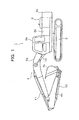
Fig. 1 is a left side view of a hydraulic excavator as a construction machine to which a hydraulic drive device according to a first embodiment of the present invention is applied; -
Fig. 2 is a hydraulic circuit diagram of the hydraulic drive device according to the first embodiment of the present invention; -
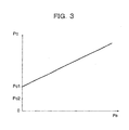
Fig. 3 is a diagram showing the relationship between a pilot pressure generated by an operating lever device shown inFig. 2 and a control pressure (control signal) generated by a pressure control valve; -
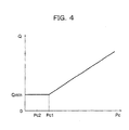
Fig. 4 is a diagram showing the characteristic of the discharge rate of a main pump (variable displacement hydraulic pump) shown inFig. 2 , with respect to the control pressure (control signal) shown inFig. 3 ; -
Fig. 5 is a flowchart showing the flow of processing performed by a controller shown inFig. 2 ; -
Fig. 6 is a diagram showing the characteristic of the discharge rate of the variable displacement hydraulic pump with respect to the control pressure, which is different from the characteristic shown inFig. 2 ; and -
Fig. 7 is a hydraulic circuit diagram of a hydraulic drive device according to a second embodiment of the present invention. - A hydraulic drive device for a construction machine according to each of first and second embodiments of the present invention will be described.
- A hydraulic drive device for a construction machine according to a first embodiment will be described with reference to
Figs. 1 to 5 . - As shown in
Fig. 1 , ahydraulic excavator 1 has atravelling body 2 that travels by driving crawlers, aswing body 3 swingably coupled to thetravelling body 2, and afront attachment 4 provided at substantially the center of the front of theswing body 3. Theswing body 3 has acabin 3a provided to the left of thefront attachment 4, a counterweight 3c that forms the rear end of theswing body 3, and amachine room 3b formed so as to extend between the rear of thecabin 3a and thecounterweight 3c. Thefront attachment 4 is of a backhoe type, and has aboom 4a coupled to the front of theswing body 3 so as to be vertically rotatable, anarm 4b rotatably coupled to theboom 4a, and abucket 4c rotatably coupled to thearm 4b. - The
hydraulic excavator 1 includes plural hydraulic actuators for driving each of thetravelling body 2, theswing body 3, and thefront attachment 4. Those plural hydraulic actuators are, specifically, a left travel motor (not shown) and a right travel motor (not shown) that drive the left and right crawlers of thetravelling body 2, respectively, a swing motor (not shown) that drives theswing body 3, aboom cylinder 10 that drives theboom 4a, anarm cylinder 11 that drives thearm 4b, and abucket cylinder 12 that drives thebucket 4c. Discharge oil from themain pump 13 formed by a variable displacement hydraulic pump shown inFig. 2 is supplied to each of these hydraulic actuators. Themain pump 13 is driven by anengine 16. - The
main pump 13 has avariable mechanism portion 14 that makes discharge rate variable by tilting of aswash plate 14a, and aregulator 15 that drives thevariable mechanism portion 14. Theregulator 15 operates when given a control signal in the form of hydraulic pressure, in other words, control pressure Pc, and drives thevariable mechanism portion 14. Arelief valve 18 is connected to amain line 17 that guides pressure oil from themain pump 13 to anarm control valve 19 and the like. The upper limit on the discharge pressure of themain pump 13 is regulated by therelief valve 18. - Between the
main pump 13 and the left travel motor, between themain pump 13 and the right travel motor, between themain pump 13 and the swing motor, between themain pump 13 and theboom cylinder 10, between themain pump 13 and thearm cylinder 11, and between themain pump 13 and thebucket cylinder 12, hydraulic pilot control valves that control the operations of those respective hydraulic actuators are provided. The control valves each control the direction and rate of flow of pressure oil supplied to each of the hydraulic actuators such as the left travel motor, the right travel motor, the swing motor, theboom cylinder 10, thearm cylinder 11, and thebucket cylinder 12. InFig. 2 , for the sake of simplicity, only thearm control valve 19 is depicted among those control valves, and also, thearm cylinder 11 corresponding to thearm control valve 19 is depicted as representing the left travel motor, the right travel motor, theboom cylinder 10, thearm cylinder 11, and thebucket cylinder 12. - The
engine 16 also drives apilot pump 20 formed by a fixed displacement hydraulic pump, in addition to themain pump 13. Although not shown, a left-travel operating lever device, a right-travel operating lever device, a swing/arm operating lever device, and a boom/bucket operating lever device are provided inside thecabin 3a. These operating lever devices are each supplied with the discharge pressure of thepilot pump 20 via asupply line 21, and generate a pilot pressure applied to each of the control valves mentioned above. Arelief valve 22 is connected to thesupply line 21. The upper limit on the discharge pressure of thepilot pump 20 is regulated by therelief valve 22. InFig. 2 , for the sake of simplicity, only an operatinglever device 23 for operating thearm control valve 19 mentioned above is depicted among those operating lever devices. - The
supply line 21 is provided with agate lock valve 24 that can shut off supply of pressure oil from thepilot pump 20 to the operatinglever device 23. Thegate lock valve 24 is an solenoid valve of a spring return type. The normal position of thegate lock valve 24 is set to a shut-off position S, and the actuated position of thegate lock valve 24 is set to a communicating position R. The communicating position R is a valve position for allowing communication between thepilot pump 20 and the operatinglever device 23, and the shut-off position S is a valve position for shutting off communication between thepilot pump 20 and the operatinglever 23 while allowing communication between the operatinglever device 23 and ahydraulic oil tank 25. - A
gate lock lever 26 is provided near the side of a operator's seat in thecabin 3a. Thegate lock lever 26 is operated to switch between a close position in which thegate lock lever 26 projects obliquely toward the boarding entrance to thecabin 3a to close the boarding entrance, and an open position in which thegate lock lever 26 retracts toward the side of the operator's seat to open the boarding entrance. Thegate lock lever 26 is provided with alever switch 27 that outputs a gate close signal upon detecting that thegate lock lever 26 is in the close position, and outputs a gate open signal upon detecting that thegate lock lever 26 is in the open position. These gate close signal and gate open signal are outputted to acontroller 80. - The
controller 80 includes a CPU (Central Processing Unit), a ROM (Read Only Memory) storing a control program and data, a RAM (Random Access Memory) used as the working area of the CPU, and the like. Thecontroller 80 performs processing related to control of the hydraulic excavator by reading the control program and data stored in the ROM. With input of a gate close signal from thelever switch 27 as a trigger, thecontroller 80 supplies current to asolenoid 24a of thegate lock valve 24 to switch the valve position from the shut-off position S to the communicating position R, and when a gate open signal from thelever switch 27 is inputted, thecontroller 80 stops the supply of current to thesolenoid 24a to return the valve position of thegate lock valve 24 from the communicating position R to the shut-off position S. -
Pilot lines lever device 23 tohydraulic pilot portions arm control valve 19, respectively. Each of a pair of inlets of a high pressure preferencetype shuttle valve 37 is connected to each of thepilot lines type shuttle valve 37 is a valve that selects the higher one of the pressure in thepilot line 34 and the pressure in thepilot line 35, as a pilot pressure for operating apressure control valve 38. Thepressure control valve 38 has ahydraulic pilot portion 38a that admits the pilot pressure from the high pressure preferencetype shuttle valve 37 through apilot line 36, aninlet 38b for admitting the discharge pressure of thepilot pump 20 through afirst branch line 39 branched off from thesupply line 21, and anoutlet 38c for discharging control pressure Pc to be applied to theregulator 15. As described above, control pressure Pc is a control signal for controlling theregulator 15. The valve position of thepressure control valve 38 varies with pilot pressure Pa applied to thehydraulic pilot portion 38a, and thus control pressure Pc is generated from the discharge pressure of thepilot pump 20. Thepressure control valve 38 is a discharge rate control unit that controls the discharge rate of themain pump 13 by a control signal. - As shown in
Fig. 3 , in the state when the valve position of thegate lock valve 24 is the communicating position R, pilot pressure Pa applied to thehydraulic pilot portion 38a of thepressure control valve 38 rises with increase in the amount of lever operation of the operatinglever device 23. Control pressure Pc rises from control pressure Pc1 in proportion to this rise in pilot pressure Pa. When the valve position of thegate lock valve 24 is the shut-off position S, thefirst branch line 39 is in communication with thehydraulic oil tank 25 via thesupply line 21 and thegate lock valve 24, and generation of pilot pressure Pa by the operatinglever device 23 is not performed. Thus, control pressure Pc generated by thepressure control valve 38 is equal to tank pressure Pt (substantially zero [Pa]). As shown inFig. 4 , the relationship between the discharge rate Q of themain pump 13 and control pressure Pc is set such that discharge rate Q is Qmin when control pressure Pc is in the range of "0≤Pc≤Pc1", and discharge rate Q is proportional to control pressure Pc when control pressure Pc is in the range of "Pc1 <Pc". Control pressure Pc1 is the minimum control pressure generated by thepressure control valve 38 in the state when the valve position of thegate lock valve 24 is the communicating position R. Also, control pressure Pc1 is a pressure for regulating the discharge rate Q of themain pump 13 to the lower limit for use in thehydraulic excavator 1, for example, minimum discharge rate Qmin. It should be noted that the lower limit on discharge rate Q for use in thehydraulic excavator 1 is not limited to minimum discharge rate Qmin as given by the specifications (performance) of themain pump 13 but may be larger than the minimum discharge rate. - Returning to
Fig. 2 , an exhaust pipe 50 of theengine 16 is provided with an exhaustemission control device 51. The exhaustemission control device 51 is provided with an exhaust filter (not shown) that captures particulate matter in the exhaust gas passing through the exhaust pipe 50, and adifferential pressure sensor 51a that detects the differential pressure between the exhaust gas pressure on the upstream side of this exhaust filter and the exhaust gas pressure on the downstream side and converts the detected differential pressure into a differential pressure detection signal (electrical signal). As clogging of the exhaust filter of the exhaustemission control device 51 increases, the channel resistance to the exhaust gas increases, and the exhaust gas pressure on the upstream side becomes higher than that on the downstream side. Thedifferential pressure sensor 51a detects the differential pressure due to the increase in channel resistance, and outputs the resulting differential pressure detection signal to thecontroller 80 mentioned above. - The
controller 80 has aregeneration control unit 81. Theregeneration control unit 81 is set by the control program and data stored in the ROM. Theregeneration control unit 81 judges whether or not a differential pressure detection signal indicates a differential pressure equal to or higher than a predetermined differential pressure, and also whether or not a gate open signal from thelever switch 27 has been inputted. Theregeneration control unit 81 performs regeneration control of the exhaust filter when theregeneration control unit 81 obtains a judgment result that the differential detection signal indicates a differential pressure equal to or higher than a predetermined differential pressure, and that a gate open signal from thelever switch 27 has been inputted. The predetermined differential pressure is set as the differential pressure in the case when the exhaust filter has become clogged to such an extent that it is necessary to regenerate the function of the exhaust filter. Aproportional solenoid valve 52 is controlled in the regeneration control. Theproportional solenoid valve 52 is a pressure control valve of a proportional electromagnetic type which is actuated when current is supplied to asolenoid 52a. Theproportional solenoid valve 52 admits the discharge pressure of thepilot pump 20 from aninlet 52b through asecond branch line 53. When actuated, theproportional solenoid valve 52 generates control pressure Pc from the discharge pressure of thepilot pump 20, and discharges the control pressure Pc from anoutlet 52c. The control pressure Pc at this time is set to control pressure Pc3 (Pc3>Pc1) of a pressure value at which the discharge rate of themain pump 13 becomes a discharge rate for regeneration. This discharge rate for regeneration is set for the purpose of applying to theengine 16 a load for raising the temperature of exhaust gas to a sufficient temperature for particulate matter to burn. It should be noted that a variable throttle that can be electrically operated by thecontroller 80 may be added to themain line 17 so that in the regeneration control, not only the discharge rate of themain pump 13 but also the discharge pressure of themain pump 13 can be raised, in other words, so that a load can be applied to theengine 16 by both the discharge rate and the discharge pressure. - A warm-
up switch 60 that is operated to output a warm-up command signal (electrical signal) is provided inside thecabin 3a. Thecontroller 80 includes a warm-upcontrol unit 82. The warm-upcontrol unit 82 is set by the control program and data stored in the ROM. The warm-upcontrol unit 82 performs warm-up control when a warm-up command signal from the warm-up switch 60 is inputted. In this warm-up control, theproportional solenoid valve 52 is actuated by supplying current to thesolenoid 52a. The control pressure Pc at this time is set to control pressure Pc4 (Pc4>Pc1) of a pressure value at which the discharge rate of themain pump 13 becomes a discharge rate for warm-up operation. The discharge rate for warm-up operation is set for the purpose of warming hydraulic oil, in other words, performing warm-up operation, by circulating the hydraulic oil within the hydraulic circuit. - The
outlet 52c of theproportional solenoid valve 52 and theoutlet 38c of thepressure control valve 38 mentioned above are each connected to each of a pair of inlets of a high pressure preferencetype shuttle valve 70. The pressure on the high pressure side selected by the high pressure preferencetype shuttle valve 70 is applied to theregulator 15 as control pressure Pc. Thesecond branch line 53 is located on the upstream side of thegate lock valve 24 in the direction of the flow of pressure oil caused by thepilot pump 20, whereas thefirst branch line 39 mentioned above is located downstream of thegate lock valve 24. Therefore, the state in which the valve position of thegate lock valve 24 is controlled to the shut-off position S is a state in which theregulator 15 of themain pump 13 can be controlled only by control pressure Pc generated by theproportional solenoid valve 52 out of theproportional solenoid valve 52 and thepressure control valve 38. - A control line 71 that guides control pressure Pc from the high pressure preference
type shuttle valve 70 to theregulator 15 is provided with apressure sensor 72, which serves as a signal detecting unit that detects control pressure Pc (control signal) applied to theregulator 15. The control pressure Pc detected by thepressure sensor 72 is converted into a pressure detection signal formed by an electrical signal and outputted to thecontroller 80. - In the first embodiment, in particular, the
controller 80 includes anengine stopping unit 83 that stops theengine 16 when thehydraulic excavator 1 is in a predetermined state. Anengine controller 16a that includes a CPU, a ROM, a RAM, and the like and controls a fuel injector is attached to theengine 16. Theengine stopping unit 83 stops theengine 16 by performing an engine stopping process that commands theengine controller 16a to stop the fuel injector. Theengine stopping unit 83 is set by the control program and data stored in the ROM, and has a controlsignal judging unit 84 and atimer 85, each serving as a unit that judges whether or not thehydraulic excavator 1 is in a predetermined state. - The control
signal judging unit 84 judges whether or not the pressure value (signal value) of control pressure Pc (control signal) based on the pressure detection signal is lower than a predetermined pressure value. The predetermined pressure value is a pressure value for controlling the discharge rate of themain pump 13 to the lower limit (minimum discharge rate Qmin in this embodiment) for use in thehydraulic excavator 1, in other words, the pressure value of control pressure Pc1 generated by thepressure control valve 38 in the state when the valve position of thegate lock valve 24 is the communicating position R and when manipulated variable of the operatinglever device 23 is zero. The controlsignal judging unit 84 stores threshold pressure Pc2 smaller than the control pressure Pc1 and larger than a tank pressure in advance, and is set to judge whether or not control pressure Pc based on a pressure detection signal is lower than the threshold pressure Pc2. - The
timer 85 judges, on the basis of clock frequency, whether or not predetermined period of time T, for example, three minutes has elapsed since a judgment result that control pressure Pc based on a pressure detection signal is lower than the threshold pressure Pc2 is obtained. - The hydraulic drive device according to the first embodiment operates as in "(1)", "(2)", and "(3)" below, in the state in which the
gate lock lever 26 is operated into the open position. - When the
gate lock lever 26 is operated from the close position to the open position, the valve position of thegate lock valve 24 switches from the communicating position R to the shut-off position S. At this time, thelever switch 27 outputs a gate open signal, and this gate open signal is inputted to thecontroller 80. On the other hand, a differential pressure detection signal from thedifferential pressure sensor 51a of the exhaustemission control device 51 is also inputted to thecontroller 80. Then, theregeneration control unit 81 of thecontroller 80 judges whether or not, in the state in which the gate open signal has been inputted, the differential pressure detection signal indicates a predetermined differential pressure or more. Suppose that at the present time, theregeneration control unit 81 has judged that the differential pressure detection signal indicates a predetermined differential pressure or more. That is, suppose that clogging of the exhaust filter that necessitates regeneration of the function of the exhaust filter has been detected. In this case, theregeneration control unit 81 performs regeneration control. That is, theproportional solenoid valve 52 is actuated by supplying current to thesolenoid 52a, and thus theproportional solenoid valve 52 generates control pressure Pc3 from the discharge pressure of thepilot pump 20 and discharges this control pressure Pc3 from theoutlet 52c. Currently, the valve position of thegate lock valve 24 is the shut-off position S, and thus control pressure Pc generated by thepressure control valve 38 is tank pressure Pt (substantially zero [Pa]). Therefore, control pressure Pc3 generated by theproportional solenoid valve 52 is applied to theregulator 15 of themain pump 13 through the high pressure preferencetype shuttle valve 70 and the control line 71, and the discharge flow rate of themain pump 13 rises from minimum discharge rate Qmin to the discharge rate for regeneration. As a result, the load of theengine 16 rises, the temperature of exhaust gas rises to a sufficient temperature for particulate matter to burn, and clogging of the exhaust filter is removed, in other words, the function of the exhaust filter is regenerated. - While regeneration control is performed in this way, the
pressure sensor 72 detects control pressure Pc3 applied to theregulator 15 of themain pump 13, and outputs a pressure detection signal corresponding to the detected control pressure Pc3. This pressure detection signal is inputted to thecontroller 80. Following this, in thecontroller 80, as shown inFig. 5 , the controlsignal judging unit 84 of theengine stopping unit 83 judges whether or not control pressure Pc3 indicated by the pressure detection signal is lower than threshold pressure Pc2 (step S1), and also starts counting by thetimer 85. At the present time, theengine stopping unit 83 obtains by the control signal judging unit 84 a judgment result that control pressure Pc3 is higher than threshold pressure Pc2 (NO in step S1), and resets the timer 85 (step S4). That is, theengine stopping unit 83 judges that the current state is a state in which driving of themain pump 13 by theengine 16 is required, in other words, thehydraulic excavator 1 is in a state inappropriate for stopping theengine 16, and thus does not perform stopping of theengine 16. - When the warm-
up switch 60 is operated to output a warm-up command signal, this warm-up command signal is inputted to thecontroller 80. Following this, the warm-upcontrol unit 82 of thecontroller 80 performs warm-up control. That is, theproportional solenoid valve 52 is actuated by supplying current to thesolenoid 52a, and thus theproportional solenoid valve 52 generates control pressure Pc4 from the discharge pressure of thepilot pump 20 and discharges this control pressure Pc4 from theoutlet 52c. Currently, the valve position of thegate lock valve 24 is the shut-off position S, and therefore control pressure Pc generated by thepressure control valve 38 is tank pressure Pt (substantially zero [Pa]). Thus, control pressure Pc4 generated by theproportional solenoid valve 52 is applied to theregulator 15 of themain pump 13 through the high pressure preferencetype shuttle valve 70 and the control line 71, and the discharge flow rate of themain pump 13 rises from minimum discharge rate Qmin to the discharge rate for warm-up operation. As a result, hydraulic oil circulates within the hydraulic circuit and warms up. - While warm-up control is performed in this way, the
pressure sensor 72 detects control pressure Pc4 applied to theregulator 15 of themain pump 13, and outputs a pressure detection signal corresponding to the detected control pressure Pc4. This pressure detection signal is inputted to thecontroller 80. Following this, in thecontroller 80, as shown inFig. 5 , the controlsignal judging unit 84 of theengine stopping unit 83 judges whether or not control pressure Pc4 indicated by the pressure detection signal is lower than threshold pressure Pc2 (step S1), and also starts counting by thetimer 85. At the present time, since warm-up control is being performed, theengine stopping unit 83 obtains by the control signal judging unit 84 a judgment result that control pressure Pc4 is higher than threshold pressure Pc2 (NO in step S1), and resets the timer 85 (step S4). That is, theengine stopping unit 83 judges that the current state is a state in which driving of themain pump 13 by theengine 16 is required, in other words, thehydraulic excavator 1 is in a state inappropriate for stopping theengine 16, and thus does not perform stopping of theengine 16. (3) Operation when not performing regeneration control and warm-up control - In the case when the
controller 80 performs neither regeneration control nor warm-up control, control pressure Pc generated by theproportional solenoid valve 52 is the tank pressure (substantially zero [Pa]). At this time, since the valve position of thegate lock valve 24 is the shut-off position S, control pressure Pc generated by thepressure control valve 38 is also the tank pressure. That is, control pressure Pc applied to theregulator 15 of themain pump 13 through the high pressure preferencetype shuttle valve 70 and the control line 71 is tank pressure Pt. Thepressure sensor 72 detects this tank pressure Pt, and outputs to the controller 80 a pressure detection signal corresponding to the detected tank pressure Pt. This pressure detection signal is inputted to thecontroller 80. Following this, in thecontroller 80, as shown inFig. 5 , the controlsignal judging unit 84 of theengine stopping unit 83 judges whether or not control pressure Pc indicated by the pressure detection signal is lower than threshold pressure Pc2 (step S1), and also starts counting by thetimer 85. Then, at the present time, since control pressure Pc is tank pressure Pt, theengine stopping unit 83 obtains by the control signal judging unit 84a a judgment result that control pressure Pc is lower than threshold pressure Pc2 (YES in step S1). Then, until predetermined period of time T (three minutes) is counted by thetimer 85, the judgment of whether or not control pressure Pc is lower than threshold pressure Pc2 is repeated (repetition of NO in step S2 and then YES in step S1), and if the judgment result that control pressure Pc is lower than threshold pressure Pc2 is continuously obtained (YES in step S2), theengine stopping unit 83 performs the engine stopping process, and commands theengine controller 16a to stop the fuel injector (step S3). That is, theengine stopping unit 83 judges that the current state is a state in which driving of themain pump 13 by theengine 16 is not required, in other words, thehydraulic excavator 1 is in a state appropriate for stopping theengine 16, and thus stops theengine 16. - Stopping the
engine 16 in this way contributes to reducing wasted fuel consumption, and also reducing environmental destruction such as global warming due to exhaust gas in the case when, for example, the operator leaves thecabin 3a without stopping theengine 16 with the intention of coming back soon, and thereafter does not come back to thecabin 3a even after predetermined period of time T (three minutes) has elapsed. - It should be noted that in the case when control pressure Pc rises above threshold pressure Pc2, such as when warm-up control is started, and when the
hydraulic excavator 1 is operated again, before predetermined period of time T (three minutes) is counted by thetimer 85, a routine process of "NO in step S2, then NO in step S1, and then step S4" is performed, and theengine 16 is not stopped. - The hydraulic drive device according to the first embodiment provides the following advantageous effects.
- In the hydraulic drive device according to the first embodiment, when stopping the
engine 16, theengine stopping unit 83 judges, by the controlsignal judging unit 84, whether or not control pressure Pc for theregulator 15 is lower than threshold pressure Pc2, in other words, whether or not control pressure Pc is lower than control pressure Pc1 for controlling the discharge rate of themain pump 13 to the lower limit (minimum discharge rate Qmin) for use in thehydraulic excavator 1. The state when the discharge rate of themain pump 13 is lower than its lower limit for use in thehydraulic excavator 1 is a state when neither regeneration control of the exhaust filter nor a warm-up operation for warming hydraulic oil is performed, in other words, a state appropriate for stopping theengine 16. That is, the hydraulic drive device according to the first embodiment can reliably judge by the controlsignal judging unit 84 whether or not the state of thehydraulic excavator 1 is appropriate for stopping theengine 16. - It should be noted that the hydraulic drive device according to the first embodiment described above includes the main pump 13 (variable displacement hydraulic pump). While the
main pump 13 has a characteristic such that the relationship between discharge rate Q and control pressure Pc is as shown inFig. 4 , the characteristic of the variable displacement hydraulic pump according to an embodiment of the present invention is not limited to the one shown inFig. 4 but may be the characteristic shown inFig. 6 , in other words, a characteristic such that discharge rate Q is proportional to control pressure Pc when control pressure Pc is in the range of "0<Pc". In this case, control pressure Pc1 is a pressure for regulating the lower limit on discharge rate Q of themain pump 13 for use in thehydraulic excavator 1 to, for example, discharge rate Q1 higher than minimum discharge rate Qmin. - A hydraulic drive device according to a second embodiment will be described with reference to
Figs. 6 and7 . - The hydraulic drive device according to the second embodiment has a
main pump 90 having the characteristic shown inFig. 6 , instead of themain pump 13 according to the first embodiment. In correspondence with the provision of themain pump 90, atilt angle sensor 91 is provided instead of thepressure sensor 72 according to the first embodiment, and further, theengine stopping unit 83 has a dischargerate judging unit 92 instead of the controlsignal judging unit 84 according to the first embodiment. - The
tilt angle sensor 91 detects the tilt angle of theswash plate 14a of thevariable mechanism portion 14, and outputs a tilt angle detection signal corresponding to the detected tilt angle to thecontroller 80. Thetilt angle sensor 91 is provided as a discharge rate detecting unit that detects the discharge rate of themain pump 90. - The discharge
rate judging unit 92 judges whether or not the tilt angle detected by the tilt angle sensor 91 (discharge rate detecting unit) corresponds to a discharge rate lower than the lower limit (discharge rate Q1) on the discharge rate of themain pump 90 for use in thehydraulic excavator 1, for example, minimum discharge rate Qmin (seeFig. 6 ). Theengine stopping unit 83 stops theengine 16 when theengine stopping unit 83 obtains a judgment result that the discharge rate Q of themain pump 90 is minimum discharge rate Qmin. - In the second embodiment configured in this way, processing in the
controller 80 partially differs from that in the flowchart shown inFig. 5 . Specifically, the difference is that in step S1, the judgment by the dischargerate judging unit 92, in other words, the judgment as to whether or not the tilt angle detected by the tilt angle sensor 91 (discharge rate detecting unit) corresponds to minimum discharge rate Qmin is performed. Otherwise, the processing is the same as that shown inFig. 5 . - The hydraulic drive device according to the second embodiment provides the following advantageous effects.
- In the hydraulic drive device according to the second embodiment, both regeneration control of the exhaust filter and warm-up operation for warming hydraulic oil are performed by controlling control pressure Pc to be a control pressure (Pc3, Pc4) higher than control pressure Pc1, in other words, by making discharge rate Q of the
main pump 90 higher than its lower limit (discharge rate Qmin) for use in thehydraulic excavator 1. That is, the state when discharge rate Q of themain pump 90 is lower than its lower limit for use in thehydraulic excavator 1 is a state when neither regeneration control nor warm-up operation is performed, in other words, a state appropriate for stopping theengine 16. When stopping theengine 16, theengine stopping unit 83 judges, by the dischargerate judging unit 92, whether or not the discharge rate of themain pump 90 corresponding to the tilt angle detected by thetilt angle sensor 91 is minimum discharge rate Qmin, and stops theengine 16 when theengine stopping unit 83 obtains a judgment result that the discharge rate Q of themain pump 90 is minimum discharge rate Qmin. Thus, whether or not the state of thehydraulic excavator 1 is appropriate for stopping theengine 16 can be reliably judged. - It should be noted that in the hydraulic drive device according to the second embodiment described above, the discharge
rate judging unit 92 makes the judgment of whether or not the discharge rate of themain pump 90 is lower than its lower limit (discharge rate Q1) for use in thehydraulic excavator 1, by using minimum discharge rate Qmin as the judgment criterion. According to an embodiment of the present invention, the discharge rate that serves as the judgment criterion is not limited to minimum discharge rate Qmin but may be a discharge rate lower than discharge rate Q1 as the lower limit but higher than minimum discharge rate Qmin. In this case, a discharge rate judging unit to be provided instead of the dischargerate judging unit 92 judges whether or not the discharge rate of themain pump 90 is equal to or lower than a predetermined discharge rate.
Claims (4)
- A hydraulic drive device for a construction machine, comprising:a variable displacement hydraulic pump;a discharge rate control unit that controls a discharge rate of the variable displacement hydraulic pump by a control signal;an engine that drives the variable displacement hydraulic pump;an engine stopping unit that stops the engine when a predetermined state of the construction machine has continued for a predetermined period of time; anda signal detecting unit that detects the control signal,wherein: the engine stopping unit has a control signal judging unit that judges whether or not a signal value of the control signal detected by the signal detecting unit is lower than a predetermined signal value, as a judgment of whether or not the predetermined state is present; andthe engine stopping unit stops the engine when a judgment result that the signal value of the control signal is lower than the predetermined signal value is obtained by the control signal judging unit.
- The hydraulic drive device for a construction machine according to Claim 1, wherein the predetermined signal value is a signal value for controlling the discharge rate of the variable displacement hydraulic pump to a lower limit for use in the construction machine.
- A hydraulic drive device for a construction machine, comprising:a variable displacement hydraulic pump;an engine that drives the variable displacement hydraulic pump;an engine stopping unit that stops the engine when a predetermined state of the construction machine has continued for a predetermined period of time; anda discharge rate detecting unit that detects a discharge rate of the variable displacement hydraulic pump,wherein: the engine stopping unit has a discharge rate judging unit that judges whether or not the discharge rate detected by the discharge rate detecting unit is equal to or lower than a predetermined discharge rate, as a judgment of whether or not the predetermined state is present; andthe engine stopping unit stops the engine when a judgment result that the discharge rate is equal to or lower than the predetermined discharge rate is obtained by the discharge rate detecting unit.
- The hydraulic drive device for a construction machine according to Claim 3, wherein the predetermined discharge rate is a discharge rate lower than a lower limit for use in the construction machine.
Applications Claiming Priority (1)
| Application Number | Priority Date | Filing Date | Title |
|---|---|---|---|
| JP2010024448A JP5363369B2 (en) | 2010-02-05 | 2010-02-05 | Hydraulic drive unit for construction machinery |
Publications (2)
| Publication Number | Publication Date |
|---|---|
| EP2354330A1 true EP2354330A1 (en) | 2011-08-10 |
| EP2354330B1 EP2354330B1 (en) | 2014-11-19 |
Family
ID=43836714
Family Applications (1)
| Application Number | Title | Priority Date | Filing Date |
|---|---|---|---|
| EP11151101.0A Active EP2354330B1 (en) | 2010-02-05 | 2011-01-17 | Engine controller for the hydraulic circuit of a construction machine |
Country Status (5)
| Country | Link |
|---|---|
| US (1) | US8726648B2 (en) |
| EP (1) | EP2354330B1 (en) |
| JP (1) | JP5363369B2 (en) |
| KR (1) | KR101775730B1 (en) |
| CN (1) | CN102162267B (en) |
Cited By (2)
| Publication number | Priority date | Publication date | Assignee | Title |
|---|---|---|---|---|
| US20140165543A1 (en) * | 2011-10-04 | 2014-06-19 | Hitachi Construction Machinery Co., Ltd. | Construction machine hydraulic drive system having exhaust gas purifying device |
| US20140290237A1 (en) * | 2011-11-29 | 2014-10-02 | Hitachi Construction Machinery Co., Ltd. | Construction machine |
Families Citing this family (14)
| Publication number | Priority date | Publication date | Assignee | Title |
|---|---|---|---|---|
| JP5523028B2 (en) * | 2009-09-04 | 2014-06-18 | 日立建機株式会社 | Hydraulic drive device for hydraulic work machine |
| US9664208B2 (en) | 2011-12-28 | 2017-05-30 | Volvo Construction Equipment Ab | Engine control method of construction machine |
| JP5923118B2 (en) * | 2012-01-25 | 2016-05-24 | 日立建機株式会社 | Construction machinery |
| US9726056B2 (en) * | 2012-05-21 | 2017-08-08 | Fca Us Llc | High efficiency oil circuit |
| CN102720241B (en) * | 2012-06-27 | 2015-04-29 | 柳工常州机械有限公司 | Control method of automatic instantaneous reinforcement control system of excavator |
| US9890518B2 (en) * | 2012-11-07 | 2018-02-13 | Hitachi Construction Mahinery Co., Ltd. | Hydraulic drive system for construction machine |
| EP3135826B1 (en) * | 2014-04-25 | 2018-10-17 | Sumitomo (S.H.I.) Construction Machinery Co., Ltd. | Construction machine and method for controlling construction machine |
| DE102015208077A1 (en) * | 2015-04-30 | 2016-11-03 | Deere & Company | generator unit |
| JP6428708B2 (en) * | 2016-04-28 | 2018-11-28 | コベルコ建機株式会社 | Construction machinery |
| JP6761283B2 (en) * | 2016-06-08 | 2020-09-23 | Kyb株式会社 | Pump device |
| JP6666208B2 (en) * | 2016-07-06 | 2020-03-13 | 日立建機株式会社 | Work machine |
| KR102609129B1 (en) * | 2016-12-21 | 2023-12-01 | 에이치디현대인프라코어 주식회사 | Construction machinery |
| CN107059982B (en) * | 2016-12-30 | 2019-06-28 | 上海华兴数字科技有限公司 | A kind of excavator locking system and locking means |
| CN113123400B (en) * | 2021-04-22 | 2022-08-05 | 潍柴动力股份有限公司 | Excavator multi-way valve core reset abnormity diagnosis method, excavator and control method |
Citations (5)
| Publication number | Priority date | Publication date | Assignee | Title |
|---|---|---|---|---|
| JPH0373380B2 (en) | 1986-04-25 | 1991-11-21 | Eagle Ind Co Ltd | |
| US6389808B1 (en) * | 1999-10-19 | 2002-05-21 | Noriyuki Sakai | Control unit for construction machine |
| EP1589211A1 (en) * | 2003-01-31 | 2005-10-26 | Kobelco Construction Machinery Co., Ltd. | Engine control device for and administration system for construction machine |
| JP3811169B2 (en) | 2004-11-09 | 2006-08-16 | 住友建機製造株式会社 | Engine control system for construction machinery |
| JP2009079500A (en) * | 2007-09-25 | 2009-04-16 | Hitachi Constr Mach Co Ltd | Exhaust emission control system for construction machine |
Family Cites Families (12)
| Publication number | Priority date | Publication date | Assignee | Title |
|---|---|---|---|---|
| US4191270A (en) * | 1977-09-01 | 1980-03-04 | Steiger Tractor, Inc. | Control for tractor power takeoff shaft |
| EP0277253B1 (en) * | 1986-08-15 | 1992-07-08 | Kabushiki Kaisha Komatsu Seisakusho | Hydraulic pump control unit |
| JP3047078B2 (en) * | 1990-11-30 | 2000-05-29 | 株式会社加藤製作所 | Automatic Governor of Engine in Load Sensing System |
| US5295790A (en) * | 1992-12-21 | 1994-03-22 | Mine Safety Appliances Company | Flow-controlled sampling pump apparatus |
| JP3073380B2 (en) | 1993-12-17 | 2000-08-07 | 日立建機株式会社 | Hydraulic working machine equipped with exhaust gas purification device |
| JP4017073B2 (en) * | 2002-10-29 | 2007-12-05 | 株式会社小松製作所 | Engine speed control device for work machines |
| JP2004251278A (en) * | 2003-01-31 | 2004-09-09 | Kobelco Contstruction Machinery Ltd | Engine controller for construction machinery and management system |
| JP4010255B2 (en) * | 2003-02-07 | 2007-11-21 | コベルコ建機株式会社 | Construction machine control equipment |
| JP2004263575A (en) * | 2003-02-17 | 2004-09-24 | Kobelco Contstruction Machinery Ltd | Engine control device of construction machine |
| WO2005054649A1 (en) * | 2003-12-02 | 2005-06-16 | Komatsu Ltd. | Construction machine |
| JP4565930B2 (en) * | 2004-08-25 | 2010-10-20 | 株式会社タダノ | Crane car engine control device |
| JP2006299825A (en) * | 2005-04-15 | 2006-11-02 | Hitachi Constr Mach Co Ltd | Warming-up operation system of construction machine |
-
2010
- 2010-02-05 JP JP2010024448A patent/JP5363369B2/en active Active
-
2011
- 2011-01-17 EP EP11151101.0A patent/EP2354330B1/en active Active
- 2011-01-19 US US13/009,302 patent/US8726648B2/en active Active
- 2011-02-01 KR KR1020110009945A patent/KR101775730B1/en active IP Right Grant
- 2011-02-01 CN CN201110035588.0A patent/CN102162267B/en active Active
Patent Citations (5)
| Publication number | Priority date | Publication date | Assignee | Title |
|---|---|---|---|---|
| JPH0373380B2 (en) | 1986-04-25 | 1991-11-21 | Eagle Ind Co Ltd | |
| US6389808B1 (en) * | 1999-10-19 | 2002-05-21 | Noriyuki Sakai | Control unit for construction machine |
| EP1589211A1 (en) * | 2003-01-31 | 2005-10-26 | Kobelco Construction Machinery Co., Ltd. | Engine control device for and administration system for construction machine |
| JP3811169B2 (en) | 2004-11-09 | 2006-08-16 | 住友建機製造株式会社 | Engine control system for construction machinery |
| JP2009079500A (en) * | 2007-09-25 | 2009-04-16 | Hitachi Constr Mach Co Ltd | Exhaust emission control system for construction machine |
Cited By (4)
| Publication number | Priority date | Publication date | Assignee | Title |
|---|---|---|---|---|
| US20140165543A1 (en) * | 2011-10-04 | 2014-06-19 | Hitachi Construction Machinery Co., Ltd. | Construction machine hydraulic drive system having exhaust gas purifying device |
| US9080481B2 (en) * | 2011-10-04 | 2015-07-14 | Hitachi Construction Machinery Co., Ltd. | Construction machine hydraulic drive system having exhaust gas purifying device |
| US20140290237A1 (en) * | 2011-11-29 | 2014-10-02 | Hitachi Construction Machinery Co., Ltd. | Construction machine |
| US9080311B2 (en) * | 2011-11-29 | 2015-07-14 | Hitachi Construction Machinery Co., Ltd. | Construction machine |
Also Published As
| Publication number | Publication date |
|---|---|
| JP2011162960A (en) | 2011-08-25 |
| CN102162267A (en) | 2011-08-24 |
| US8726648B2 (en) | 2014-05-20 |
| KR101775730B1 (en) | 2017-09-06 |
| KR20110091467A (en) | 2011-08-11 |
| US20110192156A1 (en) | 2011-08-11 |
| CN102162267B (en) | 2015-01-28 |
| JP5363369B2 (en) | 2013-12-11 |
| EP2354330B1 (en) | 2014-11-19 |
Similar Documents
| Publication | Publication Date | Title |
|---|---|---|
| EP2354330B1 (en) | Engine controller for the hydraulic circuit of a construction machine | |
| US9080481B2 (en) | Construction machine hydraulic drive system having exhaust gas purifying device | |
| KR101828116B1 (en) | Hydraulic drive system adapted for use in construction machine and provided with exhaust gas purification device | |
| US8336299B2 (en) | Exhaust gas cleaning system for construction machine | |
| US20120279203A1 (en) | Exhaust gas purification system for hydraulic operating machine | |
| US20130312616A1 (en) | Exhaust purification system for working machine | |
| EP2423481B1 (en) | Exhaust gas cleaning system for engineering vehicle | |
| JP5132662B2 (en) | DPF forced regeneration circuit for construction machinery | |
| KR20140137435A (en) | Control device and construction equipment provided therewith | |
| US8756916B2 (en) | Hydraulic driving device for working machine | |
| JP5940473B2 (en) | Hydraulic drive unit for construction machinery | |
| KR20130138224A (en) | Hydraulic working machine | |
| JP2007255506A (en) | Operation control circuit of construction machine | |
| JP2010261340A (en) | Dpf forcible regeneration circuit of construction machine | |
| EP3667102B1 (en) | Work machine | |
| JP2009275776A (en) | Fluid pressure actuator control circuit |
Legal Events
| Date | Code | Title | Description |
|---|---|---|---|
| PUAI | Public reference made under article 153(3) epc to a published international application that has entered the european phase |
Free format text: ORIGINAL CODE: 0009012 |
|
| AK | Designated contracting states |
Kind code of ref document: A1 Designated state(s): AL AT BE BG CH CY CZ DE DK EE ES FI FR GB GR HR HU IE IS IT LI LT LU LV MC MK MT NL NO PL PT RO RS SE SI SK SM TR |
|
| AX | Request for extension of the european patent |
Extension state: BA ME |
|
| 17P | Request for examination filed |
Effective date: 20111006 |
|
| 17Q | First examination report despatched |
Effective date: 20121207 |
|
| GRAP | Despatch of communication of intention to grant a patent |
Free format text: ORIGINAL CODE: EPIDOSNIGR1 |
|
| INTG | Intention to grant announced |
Effective date: 20140616 |
|
| GRAS | Grant fee paid |
Free format text: ORIGINAL CODE: EPIDOSNIGR3 |
|
| GRAA | (expected) grant |
Free format text: ORIGINAL CODE: 0009210 |
|
| AK | Designated contracting states |
Kind code of ref document: B1 Designated state(s): AL AT BE BG CH CY CZ DE DK EE ES FI FR GB GR HR HU IE IS IT LI LT LU LV MC MK MT NL NO PL PT RO RS SE SI SK SM TR |
|
| REG | Reference to a national code |
Ref country code: GB Ref legal event code: FG4D |
|
| REG | Reference to a national code |
Ref country code: CH Ref legal event code: EP |
|
| REG | Reference to a national code |
Ref country code: AT Ref legal event code: REF Ref document number: 697136 Country of ref document: AT Kind code of ref document: T Effective date: 20141215 |
|
| REG | Reference to a national code |
Ref country code: IE Ref legal event code: FG4D |
|
| REG | Reference to a national code |
Ref country code: DE Ref legal event code: R096 Ref document number: 602011011426 Country of ref document: DE Effective date: 20141231 |
|
| REG | Reference to a national code |
Ref country code: NL Ref legal event code: VDEP Effective date: 20141119 |
|
| REG | Reference to a national code |
Ref country code: AT Ref legal event code: MK05 Ref document number: 697136 Country of ref document: AT Kind code of ref document: T Effective date: 20141119 |
|
| REG | Reference to a national code |
Ref country code: LT Ref legal event code: MG4D |
|
| PG25 | Lapsed in a contracting state [announced via postgrant information from national office to epo] |
Ref country code: NO Free format text: LAPSE BECAUSE OF FAILURE TO SUBMIT A TRANSLATION OF THE DESCRIPTION OR TO PAY THE FEE WITHIN THE PRESCRIBED TIME-LIMIT Effective date: 20150219 Ref country code: NL Free format text: LAPSE BECAUSE OF FAILURE TO SUBMIT A TRANSLATION OF THE DESCRIPTION OR TO PAY THE FEE WITHIN THE PRESCRIBED TIME-LIMIT Effective date: 20141119 Ref country code: IS Free format text: LAPSE BECAUSE OF FAILURE TO SUBMIT A TRANSLATION OF THE DESCRIPTION OR TO PAY THE FEE WITHIN THE PRESCRIBED TIME-LIMIT Effective date: 20150319 Ref country code: FI Free format text: LAPSE BECAUSE OF FAILURE TO SUBMIT A TRANSLATION OF THE DESCRIPTION OR TO PAY THE FEE WITHIN THE PRESCRIBED TIME-LIMIT Effective date: 20141119 Ref country code: ES Free format text: LAPSE BECAUSE OF FAILURE TO SUBMIT A TRANSLATION OF THE DESCRIPTION OR TO PAY THE FEE WITHIN THE PRESCRIBED TIME-LIMIT Effective date: 20141119 Ref country code: LT Free format text: LAPSE BECAUSE OF FAILURE TO SUBMIT A TRANSLATION OF THE DESCRIPTION OR TO PAY THE FEE WITHIN THE PRESCRIBED TIME-LIMIT Effective date: 20141119 Ref country code: PT Free format text: LAPSE BECAUSE OF FAILURE TO SUBMIT A TRANSLATION OF THE DESCRIPTION OR TO PAY THE FEE WITHIN THE PRESCRIBED TIME-LIMIT Effective date: 20150319 |
|
| PG25 | Lapsed in a contracting state [announced via postgrant information from national office to epo] |
Ref country code: LV Free format text: LAPSE BECAUSE OF FAILURE TO SUBMIT A TRANSLATION OF THE DESCRIPTION OR TO PAY THE FEE WITHIN THE PRESCRIBED TIME-LIMIT Effective date: 20141119 Ref country code: SE Free format text: LAPSE BECAUSE OF FAILURE TO SUBMIT A TRANSLATION OF THE DESCRIPTION OR TO PAY THE FEE WITHIN THE PRESCRIBED TIME-LIMIT Effective date: 20141119 Ref country code: GR Free format text: LAPSE BECAUSE OF FAILURE TO SUBMIT A TRANSLATION OF THE DESCRIPTION OR TO PAY THE FEE WITHIN THE PRESCRIBED TIME-LIMIT Effective date: 20150220 Ref country code: RS Free format text: LAPSE BECAUSE OF FAILURE TO SUBMIT A TRANSLATION OF THE DESCRIPTION OR TO PAY THE FEE WITHIN THE PRESCRIBED TIME-LIMIT Effective date: 20141119 Ref country code: PL Free format text: LAPSE BECAUSE OF FAILURE TO SUBMIT A TRANSLATION OF THE DESCRIPTION OR TO PAY THE FEE WITHIN THE PRESCRIBED TIME-LIMIT Effective date: 20141119 Ref country code: CY Free format text: LAPSE BECAUSE OF FAILURE TO SUBMIT A TRANSLATION OF THE DESCRIPTION OR TO PAY THE FEE WITHIN THE PRESCRIBED TIME-LIMIT Effective date: 20141119 Ref country code: AT Free format text: LAPSE BECAUSE OF FAILURE TO SUBMIT A TRANSLATION OF THE DESCRIPTION OR TO PAY THE FEE WITHIN THE PRESCRIBED TIME-LIMIT Effective date: 20141119 Ref country code: HR Free format text: LAPSE BECAUSE OF FAILURE TO SUBMIT A TRANSLATION OF THE DESCRIPTION OR TO PAY THE FEE WITHIN THE PRESCRIBED TIME-LIMIT Effective date: 20141119 |
|
| PG25 | Lapsed in a contracting state [announced via postgrant information from national office to epo] |
Ref country code: EE Free format text: LAPSE BECAUSE OF FAILURE TO SUBMIT A TRANSLATION OF THE DESCRIPTION OR TO PAY THE FEE WITHIN THE PRESCRIBED TIME-LIMIT Effective date: 20141119 Ref country code: SK Free format text: LAPSE BECAUSE OF FAILURE TO SUBMIT A TRANSLATION OF THE DESCRIPTION OR TO PAY THE FEE WITHIN THE PRESCRIBED TIME-LIMIT Effective date: 20141119 Ref country code: CZ Free format text: LAPSE BECAUSE OF FAILURE TO SUBMIT A TRANSLATION OF THE DESCRIPTION OR TO PAY THE FEE WITHIN THE PRESCRIBED TIME-LIMIT Effective date: 20141119 Ref country code: DK Free format text: LAPSE BECAUSE OF FAILURE TO SUBMIT A TRANSLATION OF THE DESCRIPTION OR TO PAY THE FEE WITHIN THE PRESCRIBED TIME-LIMIT Effective date: 20141119 Ref country code: RO Free format text: LAPSE BECAUSE OF FAILURE TO SUBMIT A TRANSLATION OF THE DESCRIPTION OR TO PAY THE FEE WITHIN THE PRESCRIBED TIME-LIMIT Effective date: 20141119 |
|
| REG | Reference to a national code |
Ref country code: DE Ref legal event code: R097 Ref document number: 602011011426 Country of ref document: DE |
|
| REG | Reference to a national code |
Ref country code: CH Ref legal event code: PL |
|
| PG25 | Lapsed in a contracting state [announced via postgrant information from national office to epo] |
Ref country code: LU Free format text: LAPSE BECAUSE OF FAILURE TO SUBMIT A TRANSLATION OF THE DESCRIPTION OR TO PAY THE FEE WITHIN THE PRESCRIBED TIME-LIMIT Effective date: 20150117 |
|
| PLBE | No opposition filed within time limit |
Free format text: ORIGINAL CODE: 0009261 |
|
| STAA | Information on the status of an ep patent application or granted ep patent |
Free format text: STATUS: NO OPPOSITION FILED WITHIN TIME LIMIT |
|
| PG25 | Lapsed in a contracting state [announced via postgrant information from national office to epo] |
Ref country code: MC Free format text: LAPSE BECAUSE OF FAILURE TO SUBMIT A TRANSLATION OF THE DESCRIPTION OR TO PAY THE FEE WITHIN THE PRESCRIBED TIME-LIMIT Effective date: 20141119 |
|
| 26N | No opposition filed |
Effective date: 20150820 |
|
| PG25 | Lapsed in a contracting state [announced via postgrant information from national office to epo] |
Ref country code: LI Free format text: LAPSE BECAUSE OF NON-PAYMENT OF DUE FEES Effective date: 20150131 Ref country code: CH Free format text: LAPSE BECAUSE OF NON-PAYMENT OF DUE FEES Effective date: 20150131 |
|
| REG | Reference to a national code |
Ref country code: FR Ref legal event code: ST Effective date: 20150930 |
|
| REG | Reference to a national code |
Ref country code: IE Ref legal event code: MM4A |
|
| PG25 | Lapsed in a contracting state [announced via postgrant information from national office to epo] |
Ref country code: FR Free format text: LAPSE BECAUSE OF NON-PAYMENT OF DUE FEES Effective date: 20150202 |
|
| PG25 | Lapsed in a contracting state [announced via postgrant information from national office to epo] |
Ref country code: IT Free format text: LAPSE BECAUSE OF FAILURE TO SUBMIT A TRANSLATION OF THE DESCRIPTION OR TO PAY THE FEE WITHIN THE PRESCRIBED TIME-LIMIT Effective date: 20141119 |
|
| PG25 | Lapsed in a contracting state [announced via postgrant information from national office to epo] |
Ref country code: IE Free format text: LAPSE BECAUSE OF NON-PAYMENT OF DUE FEES Effective date: 20150117 |
|
| PG25 | Lapsed in a contracting state [announced via postgrant information from national office to epo] |
Ref country code: SI Free format text: LAPSE BECAUSE OF FAILURE TO SUBMIT A TRANSLATION OF THE DESCRIPTION OR TO PAY THE FEE WITHIN THE PRESCRIBED TIME-LIMIT Effective date: 20141119 |
|
| PG25 | Lapsed in a contracting state [announced via postgrant information from national office to epo] |
Ref country code: MT Free format text: LAPSE BECAUSE OF FAILURE TO SUBMIT A TRANSLATION OF THE DESCRIPTION OR TO PAY THE FEE WITHIN THE PRESCRIBED TIME-LIMIT Effective date: 20141119 |
|
| PG25 | Lapsed in a contracting state [announced via postgrant information from national office to epo] |
Ref country code: HU Free format text: LAPSE BECAUSE OF FAILURE TO SUBMIT A TRANSLATION OF THE DESCRIPTION OR TO PAY THE FEE WITHIN THE PRESCRIBED TIME-LIMIT; INVALID AB INITIO Effective date: 20110117 Ref country code: BG Free format text: LAPSE BECAUSE OF FAILURE TO SUBMIT A TRANSLATION OF THE DESCRIPTION OR TO PAY THE FEE WITHIN THE PRESCRIBED TIME-LIMIT Effective date: 20141119 Ref country code: SM Free format text: LAPSE BECAUSE OF FAILURE TO SUBMIT A TRANSLATION OF THE DESCRIPTION OR TO PAY THE FEE WITHIN THE PRESCRIBED TIME-LIMIT Effective date: 20141119 |
|
| PG25 | Lapsed in a contracting state [announced via postgrant information from national office to epo] |
Ref country code: BE Free format text: LAPSE BECAUSE OF NON-PAYMENT OF DUE FEES Effective date: 20150131 |
|
| PG25 | Lapsed in a contracting state [announced via postgrant information from national office to epo] |
Ref country code: TR Free format text: LAPSE BECAUSE OF FAILURE TO SUBMIT A TRANSLATION OF THE DESCRIPTION OR TO PAY THE FEE WITHIN THE PRESCRIBED TIME-LIMIT Effective date: 20141119 |
|
| PG25 | Lapsed in a contracting state [announced via postgrant information from national office to epo] |
Ref country code: MK Free format text: LAPSE BECAUSE OF FAILURE TO SUBMIT A TRANSLATION OF THE DESCRIPTION OR TO PAY THE FEE WITHIN THE PRESCRIBED TIME-LIMIT Effective date: 20141119 |
|
| PG25 | Lapsed in a contracting state [announced via postgrant information from national office to epo] |
Ref country code: AL Free format text: LAPSE BECAUSE OF FAILURE TO SUBMIT A TRANSLATION OF THE DESCRIPTION OR TO PAY THE FEE WITHIN THE PRESCRIBED TIME-LIMIT Effective date: 20141119 |
|
| PGFP | Annual fee paid to national office [announced via postgrant information from national office to epo] |
Ref country code: GB Payment date: 20200113 Year of fee payment: 10 |
|
| GBPC | Gb: european patent ceased through non-payment of renewal fee |
Effective date: 20210117 |
|
| PG25 | Lapsed in a contracting state [announced via postgrant information from national office to epo] |
Ref country code: GB Free format text: LAPSE BECAUSE OF NON-PAYMENT OF DUE FEES Effective date: 20210117 |
|
| PGFP | Annual fee paid to national office [announced via postgrant information from national office to epo] |
Ref country code: DE Payment date: 20221130 Year of fee payment: 13 |