EP2354284A1 - Plating knitting method - Google Patents
Plating knitting method Download PDFInfo
- Publication number
- EP2354284A1 EP2354284A1 EP11000862A EP11000862A EP2354284A1 EP 2354284 A1 EP2354284 A1 EP 2354284A1 EP 11000862 A EP11000862 A EP 11000862A EP 11000862 A EP11000862 A EP 11000862A EP 2354284 A1 EP2354284 A1 EP 2354284A1
- Authority
- EP
- European Patent Office
- Prior art keywords
- knitting
- plating
- knitted fabric
- yarn
- needle
- Prior art date
- Legal status (The legal status is an assumption and is not a legal conclusion. Google has not performed a legal analysis and makes no representation as to the accuracy of the status listed.)
- Granted
Links
Images



Classifications
-
- D—TEXTILES; PAPER
- D04—BRAIDING; LACE-MAKING; KNITTING; TRIMMINGS; NON-WOVEN FABRICS
- D04B—KNITTING
- D04B1/00—Weft knitting processes for the production of fabrics or articles not dependent on the use of particular machines; Fabrics or articles defined by such processes
- D04B1/22—Weft knitting processes for the production of fabrics or articles not dependent on the use of particular machines; Fabrics or articles defined by such processes specially adapted for knitting goods of particular configuration
-
- D—TEXTILES; PAPER
- D04—BRAIDING; LACE-MAKING; KNITTING; TRIMMINGS; NON-WOVEN FABRICS
- D04B—KNITTING
- D04B15/00—Details of, or auxiliary devices incorporated in, weft knitting machines, restricted to machines of this kind
- D04B15/38—Devices for supplying, feeding, or guiding threads to needles
- D04B15/54—Thread guides
- D04B15/56—Thread guides for flat-bed knitting machines
-
- D—TEXTILES; PAPER
- D04—BRAIDING; LACE-MAKING; KNITTING; TRIMMINGS; NON-WOVEN FABRICS
- D04B—KNITTING
- D04B15/00—Details of, or auxiliary devices incorporated in, weft knitting machines, restricted to machines of this kind
- D04B15/66—Devices for determining or controlling patterns ; Program-control arrangements
- D04B15/80—Devices for determining or controlling patterns ; Program-control arrangements characterised by the thread guides used
-
- D—TEXTILES; PAPER
- D10—INDEXING SCHEME ASSOCIATED WITH SUBLASSES OF SECTION D, RELATING TO TEXTILES
- D10B—INDEXING SCHEME ASSOCIATED WITH SUBLASSES OF SECTION D, RELATING TO TEXTILES
- D10B2403/00—Details of fabric structure established in the fabric forming process
- D10B2403/01—Surface features
- D10B2403/011—Dissimilar front and back faces
- D10B2403/0114—Dissimilar front and back faces with one or more yarns appearing predominantly on one face, e.g. plated or paralleled yarns
Definitions
- the present invention relates to a plating knitting method for knitting tubular knitted fabric by feeding yarns to a plurality of knitting needles provided on a needle bed of a flat knitting machine from a plating carrier which simultaneously feeds a main yarn and a plating yarn.
- plating knitting is carried out using a flat knitting machine having at least a pair of front and back needle beds.
- the plating knitting is a knitting method in which a main yarn and a plating yarn are fed to a knitting needle of the flat knitting machine to knit a tubular knitted fabric such that,the main yarn is located on a front side and the plating yarn on a back side, respectively, of the tubular knitted fabric to be completed.
- knitting yarns having different characteristics e.g., knitting yarns having different colors, shapes and elasticity are usually used.
- a carriage of the flat knitting machine is made to entrain two carriers, preceding one of the carriers is made to feed a main yarn, and the other following carrier is made to feed a plating yarn (e.g., refer to Patent Document 1) .
- the following carrier is called a plating carrier and it has a recess, into which a carrier catching pin of the carriage is fitted when the carrier is entrained by the carriage, different from that of the normal preceding carrier.
- a carriage of the flat knitting machine entrains one carrier (this carrier is also called a plating carrier) having two yarn feeders, and the carrier feeds a main yarn and a plating yarn (e.g., refer to Patent Document 2).
- this carrier is also called a plating carrier
- the carrier feeds a main yarn and a plating yarn (e.g., refer to Patent Document 2).
- the plating carrier having the two yarn feeders there are a rotary type plating carrier (see Fig. 15 of Patent Document 2), and a non-rotary type plating carrier (see Fig. 14 of Patent Document 2).
- Fig. 4 is a schematic diagram showing a lower end surface of a non-rotary type plating carrier 10 as viewed from below.
- the lower end surface of the plating carrier 10 is provided with a substantially circular yarn feeder 11 which feeds a main yarn 11A, and a long-hole yarn feeder 12 which surrounds a half circumference of the yarn feeder 11 and which feeds a plating yarn 12A.
- the yarn feeder 11 is disposed on the side of a back needle bed (BB, hereinafter), and the yarn feeder 12 is disposed on the side of a front needle bed (FB, hereinafter).
- BB back needle bed
- FB front needle bed
- the main yarn 11A can be a preceding knitting yarn irrespective of which direction (lateral direction of a sheet of the drawing) along a longitudinal direction of the needle bed the plating carrier 10 is moved as shown in Fig. 4(A) and (B) .
- the main yarn and the plating yarn intersect each other at one of ends in a knitting width direction which is an inverting position of the carrier, and the intersecting state between the main yarn and the plating yarn is reflected in the tubular knitted fabric.
- the plating carrier 10 is moved leftward on the sheet of the drawing and a back side knitted fabric part is knitted on the BB as shown in Fig. 5 (A) and then the plating carrier 10 is moved rightward on the sheet of the drawing and a front side knitted fabric part is knitted on the FB as shown in Fig. 5(B)
- the main yarn 11A and the plating yarn 12A intersect each other.
- the present invention has been accomplished in view of the above circumstances, and it is an object of the present invention to provide a plating knitting method of a tubular knitted fabric using a plating carrier, capable of stabilizing locations where a main yarn and a plating yarn intersect each other at predetermined locations in a knitting width direction of the tubular knitted fabric.
- the present invention concerns a plating knitting method, using a flat knitting machine having at least a pair of front and back needle beds, for feeding a main yarn and a plating yarn to a plurality of knitting needles provided on the needle beds to knit a tubular knitted fabric such that the main yarn is located on a front side and the plating yarn on a back side, respectively, of the tubular knitted fabric to be completed.
- the knitting is carried out in the following manner. After the one side knitted fabric part is knitted and before the knitting direction is inverted, a hooked loop is formed at the knitting needle located on an outer side, in a knitting width direction, than the knitting needle to which a terminal end stitch of the one side knitted fabric part is held. After the knitting direction is inverted, the hooked loop is released from the knitting needle and in this state, the other side knitted fabric part is knitted.
- tubular knitted fabric in the plating knitting method of the present invention, a tubular knitted fabric which is knitted by a complete circling-knitting is included of course, and knitted fabric having an opening which is knitted by a C-shaped return-knitting is also included.
- the hooked loop is formed at the knitting needle which is separated in the knitting width direction by 1 to 5 knitting needles from the knitting needle to which the terminal end stitch of the one side knitted fabric part is held.
- the hooked loop is formed at the knitting needle on the other needle bed.
- the plating yarn which is fed to the knitting needle together with the main yarn may be an elastic yarn.
- a hooked loop is formed before the other side knitted fabric part is knitted, and the hooked loop is released from the knitting needle immediately before a start end stitch of the other side knitted fabric part is formed.
- the intersection between the main yarn and the plating yarn can reliably be completed between the terminal end stitch of the one side knitted fabric part and the start end stitch of the other side knitted fabric part.
- positions where the main yarn and the plating yarn intersect each other can concentrate at predetermined positions in the knitting width direction, and a tubular knitted fabric having excellent visual quality can be knitted.
- the hooked loop in the plating knitting method of the present invention is released from the knitting needle before the other side knitted fabric part is knitted. Therefore, in a completed tubular knitted fabric, the hooked loop becomes a knitting yarn which connects the terminal end stitch of the one side knitted fabric part and the start end stitch of the other knitted fabric part. Therefore, if a position of the knitting needle which forms the hooked loop is excessively separated away from the terminal end stitch of the one side knitted fabric part, the knitting yarn which connects the terminal end stitch of the one side knitted fabric part and the start end stitch of the other knitted fabric part becomes too long, and there is an adverse possibility that visual quality of a completed tubular knitted fabric is deteriorated.
- the needle bed with which the hooked loop is formed in the plating knitting method of the present invention may be the one needle bed which knits the one side knitted fabric part or may be the other needle bed which knits the other side knitted fabric part, but if the hooked loop is formed with other needle bed, it is easy to stabilize the positions where the main yarn and the plating yarn intersect each other in a completed tubular knitted fabric on predetermined positions in the knitting width direction.
- an elastic yarn is used as the plating yarn in the plating knitting method of the present invention, it is possible to knit a stretchable tubular knitted fabric.
- a plating knitting method to knit a tubular knitted fabric by feeding a normal knitting yarn as a main yarn and an elastic yarn as a plating yarn from a plating carrier 10 shown in Fig. 4 , using a two-bed flat knitting machine having a pair of front and back needle beds extending in a lateral direction and disposed opposed to each other in a cross direction.
- the flat knitting machine to be used may be a four-bed flat knitting machine of course.
- Fig. 1 is a knitting step diagram of plating knitting
- (S + number) in a left column indicates a knitting step number
- V and "1 to 8" in a middle column respectively indicate a plating carrier and a position of a knitting needle of a needle bed
- an arrow in a right column shows a moving direction of the plating carrier.
- O indicates a stitch which is held by the knitting needle
- • indicates a stitch to be newly formed
- V indicates a hooked loop
- X indicates a knitting needle from which a hooked loop is released.
- Fig. 2 is a schematic diagram showing a state of a main yarn and a plating yarn on a needle bed corresponding to the knitting steps shown in Fig. 1 .
- S0 shows a state where a set-up portion of a tubular knitted fabric is formed by knitting needles 3 to 7 on the FB and the BB. From this state, circling-knitting is carried out in a counterclockwise direction using the plating carrier 10.
- the plating carrier 10 is moved leftward on the sheets of the drawings, a main yarn 11A and a plating yarn 12A are fed to the knitting needles 7 to 3 on the BB to knit the back side knitted fabric part (one side knitted fabric part) and then, a hooked loop is formed by the knitting needle 1 on the FB.
- S2 shows a state where a set-up portion of a tubular knitted fabric is formed by knitting needles 3 to 7 on the FB and the BB.
- the plating carrier 10 is inverted to move rightward on the sheets of the drawings, the hooked loop formed by the knitting needle 1 on the FB in S1 is released from the knitting needle 1, the main yarn 11A and the plating yarn 12A are fed to the knitting needles 3 to 7 on the FB to knit the front side knitted fabric part (the other side knitted fabric part) .
- the plating knitting method of the present invention is characterized in that the hooked loop which is released later is formed outside of the tubular knitted fabric in the knitting width direction, but a location where the hooked loop is formed is not especially limited.
- the hooked loop may be formed at the knitting needle 2 on the FB or at the knitting needle 1 or 2 on the BB shown in Figs. 1 and 2 .
- a position where the intersection location in the tubular knitted fabric is most stable is a position of the knitting needle 1 on the FB shown in the embodiment, and a next stable position is a position of the knitting needle 2 on the FB.
- the present invention is not limited to the above-described embodiment, and the embodiment of the present invention can appropriately be changed within a scope not departing from the subject matter of the present invention.
- the plating knitting of the present invention can also be applied to plating knitting using a rotary type plating carrier and plating knitting using two carriers.
Landscapes
- Engineering & Computer Science (AREA)
- Textile Engineering (AREA)
- Knitting Of Fabric (AREA)
- Knitting Machines (AREA)
Abstract
Description
- The present invention relates to a plating knitting method for knitting tubular knitted fabric by feeding yarns to a plurality of knitting needles provided on a needle bed of a flat knitting machine from a plating carrier which simultaneously feeds a main yarn and a plating yarn.
- In some cases, plating knitting is carried out using a flat knitting machine having at least a pair of front and back needle beds. The plating knitting is a knitting method in which a main yarn and a plating yarn are fed to a knitting needle of the flat knitting machine to knit a tubular knitted fabric such that,the main yarn is located on a front side and the plating yarn on a back side, respectively, of the tubular knitted fabric to be completed. As the main yarn and the plating yarn, knitting yarns having different characteristics, e.g., knitting yarns having different colors, shapes and elasticity are usually used.
- To carry out the plating knitting, there are mainly two methods. According to the first method, a carriage of the flat knitting machine is made to entrain two carriers, preceding one of the carriers is made to feed a main yarn, and the other following carrier is made to feed a plating yarn (e.g., refer to Patent Document 1) . The following carrier is called a plating carrier and it has a recess, into which a carrier catching pin of the carriage is fitted when the carrier is entrained by the carriage, different from that of the normal preceding carrier. According to the second method, a carriage of the flat knitting machine entrains one carrier (this carrier is also called a plating carrier) having two yarn feeders, and the carrier feeds a main yarn and a plating yarn (e.g., refer to Patent Document 2). As the plating carrier having the two yarn feeders, there are a rotary type plating carrier (see Fig. 15 of Patent Document 2), and a non-rotary type plating carrier (see Fig. 14 of Patent Document 2).
-
Fig. 4 is a schematic diagram showing a lower end surface of a non-rotarytype plating carrier 10 as viewed from below. The lower end surface of theplating carrier 10 is provided with a substantiallycircular yarn feeder 11 which feeds amain yarn 11A, and a long-hole yarn feeder 12 which surrounds a half circumference of theyarn feeder 11 and which feeds aplating yarn 12A. InFig. 4 , theyarn feeder 11 is disposed on the side of a back needle bed (BB, hereinafter), and theyarn feeder 12 is disposed on the side of a front needle bed (FB, hereinafter). If theplating carrier 10 is used, themain yarn 11A can be a preceding knitting yarn irrespective of which direction (lateral direction of a sheet of the drawing) along a longitudinal direction of the needle bed theplating carrier 10 is moved as shown inFig. 4(A) and (B) . -
- [Patent Document 1] PCT International Publication No.
2008/139710 - [Patent Document 2] Japanese Patent No.
3899269 - When a tubular knitted fabric is knitted using the plating carrier, the main yarn and the plating yarn intersect each other at one of ends in a knitting width direction which is an inverting position of the carrier, and the intersecting state between the main yarn and the plating yarn is reflected in the tubular knitted fabric. For example, when the
plating carrier 10 is moved leftward on the sheet of the drawing and a back side knitted fabric part is knitted on the BB as shown inFig. 5 (A) and then theplating carrier 10 is moved rightward on the sheet of the drawing and a front side knitted fabric part is knitted on the FB as shown inFig. 5(B) , themain yarn 11A and theplating yarn 12A intersect each other. However, a position of anintersection location 13, where themain yarn 11A and theplating yarn 12A intersect, is deviated toward the FB or BB depending upon a knitting course and is not stable. For this reason, according to the conventional tubular knitted fabric using the plating carrier, there is an adverse possibility that intersection locations of the main yarn and the plating yarn in each knitting course vary in a knitting width direction of the tubular knitted fabric as shown in a partial enlarged photograph inFig. 6 . This problem also occurs when two carriers are used or a rotary type plating carrier is used. - The present invention has been accomplished in view of the above circumstances, and it is an object of the present invention to provide a plating knitting method of a tubular knitted fabric using a plating carrier, capable of stabilizing locations where a main yarn and a plating yarn intersect each other at predetermined locations in a knitting width direction of the tubular knitted fabric.
- The present invention concerns a plating knitting method, using a flat knitting machine having at least a pair of front and back needle beds, for feeding a main yarn and a plating yarn to a plurality of knitting needles provided on the needle beds to knit a tubular knitted fabric such that the main yarn is located on a front side and the plating yarn on a back side, respectively, of the tubular knitted fabric to be completed. According to the plating knitting method of the present invention, when one side knitted fabric part of the tubular knitted fabric is knitted on one of the needle beds toward one of longitudinal directions of the needle bed and then a knitting direction thereof is inverted and the other side knitted fabric part of the tubular knitted fabric is knitted on the other needle bed, if the main yarn and the plating yarn intersect each other, the knitting is carried out in the following manner.
After the one side knitted fabric part is knitted and before the knitting direction is inverted, a hooked loop is formed at the knitting needle located on an outer side, in a knitting width direction, than the knitting needle to which a terminal end stitch of the one side knitted fabric part is held.
After the knitting direction is inverted, the hooked loop is released from the knitting needle and in this state, the other side knitted fabric part is knitted. - As the tubular knitted fabric in the plating knitting method of the present invention, a tubular knitted fabric which is knitted by a complete circling-knitting is included of course, and knitted fabric having an opening which is knitted by a C-shaped return-knitting is also included.
- As one aspect of the plating knitting method of the present invention, it is preferable that the hooked loop is formed at the knitting needle which is separated in the knitting width direction by 1 to 5 knitting needles from the knitting needle to which the terminal end stitch of the one side knitted fabric part is held.
- As one aspect of the plating knitting method of the present invention, it is preferable that the hooked loop is formed at the knitting needle on the other needle bed.
- As one aspect of the plating knitting method of the present invention, the plating yarn which is fed to the knitting needle together with the main yarn may be an elastic yarn.
- As shown in the plating knitting method of the present invention, after the one side knitted fabric part is knitted on a side where the main yarn and the plating yarn intersect each other, a hooked loop is formed before the other side knitted fabric part is knitted, and the hooked loop is released from the knitting needle immediately before a start end stitch of the other side knitted fabric part is formed. According to this, the intersection between the main yarn and the plating yarn can reliably be completed between the terminal end stitch of the one side knitted fabric part and the start end stitch of the other side knitted fabric part. As a result, in a completed tubular knitted fabric, positions where the main yarn and the plating yarn intersect each other can concentrate at predetermined positions in the knitting width direction, and a tubular knitted fabric having excellent visual quality can be knitted.
- Here, the hooked loop in the plating knitting method of the present invention is released from the knitting needle before the other side knitted fabric part is knitted. Therefore, in a completed tubular knitted fabric, the hooked loop becomes a knitting yarn which connects the terminal end stitch of the one side knitted fabric part and the start end stitch of the other knitted fabric part. Therefore, if a position of the knitting needle which forms the hooked loop is excessively separated away from the terminal end stitch of the one side knitted fabric part, the knitting yarn which connects the terminal end stitch of the one side knitted fabric part and the start end stitch of the other knitted fabric part becomes too long, and there is an adverse possibility that visual quality of a completed tubular knitted fabric is deteriorated. In contrast, if the position of the knitting needle at which the hooked loop is formed is within 5 knitting needles from the knitting needle to which the terminal end stitch of the one side knitted fabric part is held, it is possible to avoid a case where the knitting yarn which connects the terminal end stitch and the start end stitch becomes too long.
- The needle bed with which the hooked loop is formed in the plating knitting method of the present invention may be the one needle bed which knits the one side knitted fabric part or may be the other needle bed which knits the other side knitted fabric part, but if the hooked loop is formed with other needle bed, it is easy to stabilize the positions where the main yarn and the plating yarn intersect each other in a completed tubular knitted fabric on predetermined positions in the knitting width direction.
- If an elastic yarn is used as the plating yarn in the plating knitting method of the present invention, it is possible to knit a stretchable tubular knitted fabric.
-
-
Fig. 1 is a knitting step diagram of plating knitting according to an embodiment; -
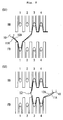
Fig. 2 is a schematic diagram showing a state of a main yarn and a plating yarn on an actual needle bed corresponding to the knitting step diagram inFig. 1 , wherein (S1) and (S2) inFig. 2 match with the knitting steps (S1) and (S2) inFig. 1 ; -
Fig. 3 is a partial enlarged photograph of knitted fabric which is knitted by plating knitting according to the embodiment; -
Fig. 4 is a schematic diagram showing a lower end surface of a typical plating carrier, wherein (A) shows a yarn feeding state of a main yarn and a plating yarn when the carrier moves leftward on a sheet of the drawing, and (B) shows a yarn feeding state of the main yarn and the plating yarn when the carrier moves rightward on the sheet of the drawing; -
Fig. 5 is a schematic diagram of states of the main yarn and the plating yarn on an actual needle bed when conventional plating knitting is carried out, wherein (A) shows a state where a plating carrier is moved leftward on the sheet of the drawing and knitting is carried out by a knitting needle on the BB, and (B) shows a state where the carrier is moved rightward on the sheet of the drawing and knitting is carried out by a knitting needle on the FB after the knitting shown in (A) is carried out; and -
Fig. 6 is a partial enlarged photograph of knitted fabric which is knitted by conventional plating knitting. - An embodiment of the present invention will be described below with reference to the drawings. In the embodiment, there is described a plating knitting method to knit a tubular knitted fabric by feeding a normal knitting yarn as a main yarn and an elastic yarn as a plating yarn from a
plating carrier 10 shown inFig. 4 , using a two-bed flat knitting machine having a pair of front and back needle beds extending in a lateral direction and disposed opposed to each other in a cross direction. The flat knitting machine to be used may be a four-bed flat knitting machine of course. -
Fig. 1 is a knitting step diagram of plating knitting, (S + number) in a left column indicates a knitting step number, V and "1 to 8" in a middle column respectively indicate a plating carrier and a position of a knitting needle of a needle bed, and an arrow in a right column shows a moving direction of the plating carrier. InFig. 1 , O indicates a stitch which is held by the knitting needle, • indicates a stitch to be newly formed, V indicates a hooked loop, and X indicates a knitting needle from which a hooked loop is released.Fig. 2 is a schematic diagram showing a state of a main yarn and a plating yarn on a needle bed corresponding to the knitting steps shown inFig. 1 . - In
Fig. 1 , S0 shows a state where a set-up portion of a tubular knitted fabric is formed by knittingneedles 3 to 7 on the FB and the BB. From this state, circling-knitting is carried out in a counterclockwise direction using theplating carrier 10. At that time, as shown with S1 inFigs. 1 and2 , theplating carrier 10 is moved leftward on the sheets of the drawings, amain yarn 11A and aplating yarn 12A are fed to the knittingneedles 7 to 3 on the BB to knit the back side knitted fabric part (one side knitted fabric part) and then, a hooked loop is formed by the knittingneedle 1 on the FB. Next, as shown with S2 inFigs. 1 and2 , theplating carrier 10 is inverted to move rightward on the sheets of the drawings, the hooked loop formed by the knittingneedle 1 on the FB in S1 is released from the knittingneedle 1, themain yarn 11A and theplating yarn 12A are fed to the knittingneedles 3 to 7 on the FB to knit the front side knitted fabric part (the other side knitted fabric part) . - If S1 and S2 described above are carried out, as shown in
Fig. 2 , when theplating carrier 10 is inverted and themain yarn 11A and theplating yarn 12A intersect each other, the intersection can stably be completed between a terminal end stitch of the back side knitted fabric part (stitch which is held by the knittingneedle 3 on the BB) and a start end stitch of the front side knitted fabric part (stitch which is held by the knittingneedle 3 on the FB). As a result, if S1 and S2 are repeated to knit the tubular knitted fabric, it is possible to concentrate theintersection locations 13 between the main yarn and the plating yarn at predetermined positions of a completed tubular knitted fabric in the knitting width direction, i.e., at positions between the terminal end stitch of the back side knitted fabric part and the start end stitch of the front side knitted fabric part. FromFig. 3 which is the partial enlarged photograph of an actually knitted tubular knitted fabric, it can be found that the intersection locations of knitting courses stably appear at predetermined positions of the tubular knitted fabric in the knitting width direction. If the tubular knitted fabric obtained by the plating knitting method of the present invention shown inFig. 3 and a tubular knitted fabric obtained by the conventional plating knitting method shown inFig. 6 are compared with each other, it is apparent that the tubular knitted fabric inFig. 3 looks much better. - The plating knitting method of the present invention is characterized in that the hooked loop which is released later is formed outside of the tubular knitted fabric in the knitting width direction, but a location where the hooked loop is formed is not especially limited. For example, the hooked loop may be formed at the
knitting needle 2 on the FB or at theknitting needle Figs. 1 and2 . Of the four positions where the hooked loop can be formed, a position where the intersection location in the tubular knitted fabric is most stable is a position of theknitting needle 1 on the FB shown in the embodiment, and a next stable position is a position of theknitting needle 2 on the FB. When the hooked loop is formed at theknitting needles - The present invention is not limited to the above-described embodiment, and the embodiment of the present invention can appropriately be changed within a scope not departing from the subject matter of the present invention. For example, the plating knitting of the present invention can also be applied to plating knitting using a rotary type plating carrier and plating knitting using two carriers.
-
- FB
- front needle bed
- BB
- back needle bed
- 1 to 8
- knitting needle
- 10
- plating carrier
- 11, 12
- yarn feeder
- 11A
- main yarn
- 12A
- plating yarn
- 13
- intersection location
Claims (4)
- A plating knitting method, using a flat knitting machine having at least a pair of front and back needle beds, for feeding a main yarn and a plating yarn to a plurality of knitting needles provided on the needle beds to knit a tubular knitted fabric such that the main yarn is located on a front side and the plating yarn on a back side, respectively, of the tubular knitted fabric to be completed, wherein
when one side knitted fabric part of the tubular knitted fabric is knitted on one of the needle beds toward one of longitudinal directions of the needle bed and then a knitting direction thereof is inverted and the other side knitted fabric part of the tubular knitted fabric is knitted on the other needle bed, in a case where the main yarn and the plating yarn intersect each other,
after the one side knitted fabric part is knitted and before the knitting direction is inverted, a hooked loop is formed at the knitting needle located on an outer side, in a knitting width direction, than the knitting needle to which a terminal end stitch of the one side knitted fabric part is held, and
after the knitting direction is inverted, the hooked loop is released from the knitting needle and in this state, the other side knitted fabric part is knitted. - The plating knitting method according to claim 1, wherein the hooked loop is formed at the knitting needle which is separated in the knitting width direction by 1 to 5 needles from the knitting needle to which the terminal end stitch of the one side knitted fabric part is held.
- The plating knitting method according to claim 1 or 2, wherein
the hooked loop is formed at the knitting needle on the other needle bed. - The plating knitting method according to any one of claims 1 to 3, wherein
the plating yarn is an elastic yarn.
Applications Claiming Priority (1)
| Application Number | Priority Date | Filing Date | Title |
|---|---|---|---|
| JP2010022532A JP5349357B2 (en) | 2010-02-03 | 2010-02-03 | Plating organization method |
Publications (2)
| Publication Number | Publication Date |
|---|---|
| EP2354284A1 true EP2354284A1 (en) | 2011-08-10 |
| EP2354284B1 EP2354284B1 (en) | 2013-07-10 |
Family
ID=43981137
Family Applications (1)
| Application Number | Title | Priority Date | Filing Date |
|---|---|---|---|
| EP11000862.0A Not-in-force EP2354284B1 (en) | 2010-02-03 | 2011-02-03 | Plating knitting method |
Country Status (3)
| Country | Link |
|---|---|
| EP (1) | EP2354284B1 (en) |
| JP (1) | JP5349357B2 (en) |
| CN (1) | CN102140725B (en) |
Families Citing this family (4)
| Publication number | Priority date | Publication date | Assignee | Title |
|---|---|---|---|---|
| JP6526554B2 (en) * | 2015-12-25 | 2019-06-05 | 株式会社島精機製作所 | Knitting method of knitted fabric |
| JP6518608B2 (en) * | 2016-03-01 | 2019-05-22 | 株式会社島精機製作所 | Method of knitting tubular knitted fabric |
| WO2018186499A1 (en) * | 2017-04-07 | 2018-10-11 | 株式会社島精機製作所 | Plating knitting method used in flat knitting machine |
| JP7341960B2 (en) * | 2020-08-06 | 2023-09-11 | 株式会社島精機製作所 | How to knit knitted fabric |
Citations (4)
| Publication number | Priority date | Publication date | Assignee | Title |
|---|---|---|---|---|
| EP1728908A1 (en) * | 2004-01-30 | 2006-12-06 | Shima Seiki Mfg., Ltd | Knitting method for wide rib texture by plating |
| JP3899269B2 (en) | 2000-02-29 | 2007-03-28 | 株式会社島精機製作所 | Yarn feeder for flat knitting machine |
| EP1918438A1 (en) * | 2006-10-26 | 2008-05-07 | H. Stoll GmbH & Co. KG | Method for producing a tubular flat knit fabric with the plating technique |
| WO2008139710A1 (en) * | 2007-05-02 | 2008-11-20 | Shima Seiki Mfg., Ltd. | Plating-knitted cylindrical fabric, knitting method therefor, and design device |
Family Cites Families (3)
| Publication number | Priority date | Publication date | Assignee | Title |
|---|---|---|---|---|
| JP3333384B2 (en) * | 1996-05-08 | 2002-10-15 | 株式会社島精機製作所 | How to knit seamless socks |
| WO2007099708A1 (en) * | 2006-02-28 | 2007-09-07 | Shima Seiki Mfg., Ltd. | Method of forming increase and knitted fabric where increases are formed inner side of knitting width direction end of knitted fabric |
| JP2010133070A (en) * | 2008-12-08 | 2010-06-17 | Shima Seiki Mfg Ltd | Flat knitting machine and knit fabric having cylindrical knitted part |
-
2010
- 2010-02-03 JP JP2010022532A patent/JP5349357B2/en not_active Expired - Fee Related
-
2011
- 2011-02-01 CN CN201110036230.XA patent/CN102140725B/en not_active Expired - Fee Related
- 2011-02-03 EP EP11000862.0A patent/EP2354284B1/en not_active Not-in-force
Patent Citations (5)
| Publication number | Priority date | Publication date | Assignee | Title |
|---|---|---|---|---|
| JP3899269B2 (en) | 2000-02-29 | 2007-03-28 | 株式会社島精機製作所 | Yarn feeder for flat knitting machine |
| EP1728908A1 (en) * | 2004-01-30 | 2006-12-06 | Shima Seiki Mfg., Ltd | Knitting method for wide rib texture by plating |
| EP1918438A1 (en) * | 2006-10-26 | 2008-05-07 | H. Stoll GmbH & Co. KG | Method for producing a tubular flat knit fabric with the plating technique |
| WO2008139710A1 (en) * | 2007-05-02 | 2008-11-20 | Shima Seiki Mfg., Ltd. | Plating-knitted cylindrical fabric, knitting method therefor, and design device |
| EP2157221A1 (en) * | 2007-05-02 | 2010-02-24 | Shima Seiki Mfg., Ltd | Plating-knitted cylindrical fabric, knitting method therefor, and design device |
Also Published As
| Publication number | Publication date |
|---|---|
| JP5349357B2 (en) | 2013-11-20 |
| CN102140725B (en) | 2014-12-03 |
| EP2354284B1 (en) | 2013-07-10 |
| CN102140725A (en) | 2011-08-03 |
| JP2011157670A (en) | 2011-08-18 |
Similar Documents
| Publication | Publication Date | Title |
|---|---|---|
| EP2390393A1 (en) | Method for preventing ravel of knitting yarn and knitted fabric | |
| EP1728908A1 (en) | Knitting method for wide rib texture by plating | |
| EP2568066B1 (en) | Set-up method of knitted fabric | |
| EP2319969B1 (en) | Knitting method of knitted fabric, and knitted fabric | |
| EP2330240B1 (en) | Knitting method of knitted fabric and knitted fabric | |
| JP5922903B2 (en) | Knitting method of knitted fabric | |
| KR20140080414A (en) | Method for preventing unraveling of knitting yarn | |
| EP1990451A1 (en) | Method of forming increase and knitted fabric where increases are formed inner side of knitting width direction end of knitted fabric | |
| EP2354284B1 (en) | Plating knitting method | |
| EP2447399B1 (en) | Knitting method on a flat knitting machine having a plurality of yarn feeders and a corresponding knitted fabric | |
| EP2290141B1 (en) | Method of knitting a tubular fabric and tubular fabric | |
| EP2327818B1 (en) | Knitting method of knitted fabric, and knitted fabric | |
| EP2546399B1 (en) | Set-up method of knitted fabric and knitted fabric | |
| JP2010053490A (en) | Method for knitting tubular knitted fabric and knitted fabric | |
| US6668594B2 (en) | Tubular fabric plating method using four-bed flat knitting machine | |
| KR19990077454A (en) | A widening method | |
| EP2636778B1 (en) | Method for preventing unraveling of knitting yarn | |
| EP2397588B1 (en) | Inner widening method | |
| JP6518608B2 (en) | Method of knitting tubular knitted fabric | |
| EP2392708A1 (en) | Method for knitting knitwear with collar having v-neck point and knitted fabric | |
| CN109322052B (en) | Method for knitting knitted fabric | |
| KR101569014B1 (en) | Method for knitting knitted fabric | |
| KR102940918B1 (en) | Knitting method of tubular knitted fabric | |
| EP2281933B1 (en) | Method for knitting knitted fabric with overlapped stitches, and knitted fabric | |
| KR102679139B1 (en) | Method for knitting knitted fabric |
Legal Events
| Date | Code | Title | Description |
|---|---|---|---|
| PUAI | Public reference made under article 153(3) epc to a published international application that has entered the european phase |
Free format text: ORIGINAL CODE: 0009012 |
|
| AK | Designated contracting states |
Kind code of ref document: A1 Designated state(s): AL AT BE BG CH CY CZ DE DK EE ES FI FR GB GR HR HU IE IS IT LI LT LU LV MC MK MT NL NO PL PT RO RS SE SI SK SM TR |
|
| AX | Request for extension of the european patent |
Extension state: BA ME |
|
| 17P | Request for examination filed |
Effective date: 20120119 |
|
| GRAP | Despatch of communication of intention to grant a patent |
Free format text: ORIGINAL CODE: EPIDOSNIGR1 |
|
| RIC1 | Information provided on ipc code assigned before grant |
Ipc: D04B 1/22 20060101AFI20121217BHEP |
|
| GRAS | Grant fee paid |
Free format text: ORIGINAL CODE: EPIDOSNIGR3 |
|
| GRAA | (expected) grant |
Free format text: ORIGINAL CODE: 0009210 |
|
| AK | Designated contracting states |
Kind code of ref document: B1 Designated state(s): AL AT BE BG CH CY CZ DE DK EE ES FI FR GB GR HR HU IE IS IT LI LT LU LV MC MK MT NL NO PL PT RO RS SE SI SK SM TR |
|
| REG | Reference to a national code |
Ref country code: GB Ref legal event code: FG4D |
|
| REG | Reference to a national code |
Ref country code: AT Ref legal event code: REF Ref document number: 621046 Country of ref document: AT Kind code of ref document: T Effective date: 20130715 Ref country code: CH Ref legal event code: EP |
|
| REG | Reference to a national code |
Ref country code: IE Ref legal event code: FG4D |
|
| REG | Reference to a national code |
Ref country code: DE Ref legal event code: R096 Ref document number: 602011002222 Country of ref document: DE Effective date: 20130905 |
|
| PG25 | Lapsed in a contracting state [announced via postgrant information from national office to epo] |
Ref country code: SI Free format text: LAPSE BECAUSE OF FAILURE TO SUBMIT A TRANSLATION OF THE DESCRIPTION OR TO PAY THE FEE WITHIN THE PRESCRIBED TIME-LIMIT Effective date: 20130710 |
|
| REG | Reference to a national code |
Ref country code: AT Ref legal event code: MK05 Ref document number: 621046 Country of ref document: AT Kind code of ref document: T Effective date: 20130710 |
|
| REG | Reference to a national code |
Ref country code: NL Ref legal event code: VDEP Effective date: 20130710 |
|
| REG | Reference to a national code |
Ref country code: LT Ref legal event code: MG4D |
|
| PG25 | Lapsed in a contracting state [announced via postgrant information from national office to epo] |
Ref country code: IS Free format text: LAPSE BECAUSE OF FAILURE TO SUBMIT A TRANSLATION OF THE DESCRIPTION OR TO PAY THE FEE WITHIN THE PRESCRIBED TIME-LIMIT Effective date: 20131110 Ref country code: CY Free format text: LAPSE BECAUSE OF FAILURE TO SUBMIT A TRANSLATION OF THE DESCRIPTION OR TO PAY THE FEE WITHIN THE PRESCRIBED TIME-LIMIT Effective date: 20130626 Ref country code: BE Free format text: LAPSE BECAUSE OF FAILURE TO SUBMIT A TRANSLATION OF THE DESCRIPTION OR TO PAY THE FEE WITHIN THE PRESCRIBED TIME-LIMIT Effective date: 20130710 Ref country code: AT Free format text: LAPSE BECAUSE OF FAILURE TO SUBMIT A TRANSLATION OF THE DESCRIPTION OR TO PAY THE FEE WITHIN THE PRESCRIBED TIME-LIMIT Effective date: 20130710 Ref country code: PT Free format text: LAPSE BECAUSE OF FAILURE TO SUBMIT A TRANSLATION OF THE DESCRIPTION OR TO PAY THE FEE WITHIN THE PRESCRIBED TIME-LIMIT Effective date: 20131111 Ref country code: LT Free format text: LAPSE BECAUSE OF FAILURE TO SUBMIT A TRANSLATION OF THE DESCRIPTION OR TO PAY THE FEE WITHIN THE PRESCRIBED TIME-LIMIT Effective date: 20130710 Ref country code: SE Free format text: LAPSE BECAUSE OF FAILURE TO SUBMIT A TRANSLATION OF THE DESCRIPTION OR TO PAY THE FEE WITHIN THE PRESCRIBED TIME-LIMIT Effective date: 20130710 Ref country code: HR Free format text: LAPSE BECAUSE OF FAILURE TO SUBMIT A TRANSLATION OF THE DESCRIPTION OR TO PAY THE FEE WITHIN THE PRESCRIBED TIME-LIMIT Effective date: 20130710 Ref country code: NO Free format text: LAPSE BECAUSE OF FAILURE TO SUBMIT A TRANSLATION OF THE DESCRIPTION OR TO PAY THE FEE WITHIN THE PRESCRIBED TIME-LIMIT Effective date: 20131010 |
|
| PG25 | Lapsed in a contracting state [announced via postgrant information from national office to epo] |
Ref country code: ES Free format text: LAPSE BECAUSE OF FAILURE TO SUBMIT A TRANSLATION OF THE DESCRIPTION OR TO PAY THE FEE WITHIN THE PRESCRIBED TIME-LIMIT Effective date: 20131021 Ref country code: LV Free format text: LAPSE BECAUSE OF FAILURE TO SUBMIT A TRANSLATION OF THE DESCRIPTION OR TO PAY THE FEE WITHIN THE PRESCRIBED TIME-LIMIT Effective date: 20130710 Ref country code: NL Free format text: LAPSE BECAUSE OF FAILURE TO SUBMIT A TRANSLATION OF THE DESCRIPTION OR TO PAY THE FEE WITHIN THE PRESCRIBED TIME-LIMIT Effective date: 20130710 Ref country code: GR Free format text: LAPSE BECAUSE OF FAILURE TO SUBMIT A TRANSLATION OF THE DESCRIPTION OR TO PAY THE FEE WITHIN THE PRESCRIBED TIME-LIMIT Effective date: 20131011 Ref country code: PL Free format text: LAPSE BECAUSE OF FAILURE TO SUBMIT A TRANSLATION OF THE DESCRIPTION OR TO PAY THE FEE WITHIN THE PRESCRIBED TIME-LIMIT Effective date: 20130710 Ref country code: FI Free format text: LAPSE BECAUSE OF FAILURE TO SUBMIT A TRANSLATION OF THE DESCRIPTION OR TO PAY THE FEE WITHIN THE PRESCRIBED TIME-LIMIT Effective date: 20130710 |
|
| PG25 | Lapsed in a contracting state [announced via postgrant information from national office to epo] |
Ref country code: CY Free format text: LAPSE BECAUSE OF FAILURE TO SUBMIT A TRANSLATION OF THE DESCRIPTION OR TO PAY THE FEE WITHIN THE PRESCRIBED TIME-LIMIT Effective date: 20130710 |
|
| PG25 | Lapsed in a contracting state [announced via postgrant information from national office to epo] |
Ref country code: DK Free format text: LAPSE BECAUSE OF FAILURE TO SUBMIT A TRANSLATION OF THE DESCRIPTION OR TO PAY THE FEE WITHIN THE PRESCRIBED TIME-LIMIT Effective date: 20130710 Ref country code: SK Free format text: LAPSE BECAUSE OF FAILURE TO SUBMIT A TRANSLATION OF THE DESCRIPTION OR TO PAY THE FEE WITHIN THE PRESCRIBED TIME-LIMIT Effective date: 20130710 Ref country code: CZ Free format text: LAPSE BECAUSE OF FAILURE TO SUBMIT A TRANSLATION OF THE DESCRIPTION OR TO PAY THE FEE WITHIN THE PRESCRIBED TIME-LIMIT Effective date: 20130710 Ref country code: EE Free format text: LAPSE BECAUSE OF FAILURE TO SUBMIT A TRANSLATION OF THE DESCRIPTION OR TO PAY THE FEE WITHIN THE PRESCRIBED TIME-LIMIT Effective date: 20130710 Ref country code: RO Free format text: LAPSE BECAUSE OF FAILURE TO SUBMIT A TRANSLATION OF THE DESCRIPTION OR TO PAY THE FEE WITHIN THE PRESCRIBED TIME-LIMIT Effective date: 20130710 |
|
| PLBE | No opposition filed within time limit |
Free format text: ORIGINAL CODE: 0009261 |
|
| STAA | Information on the status of an ep patent application or granted ep patent |
Free format text: STATUS: NO OPPOSITION FILED WITHIN TIME LIMIT |
|
| 26N | No opposition filed |
Effective date: 20140411 |
|
| REG | Reference to a national code |
Ref country code: DE Ref legal event code: R097 Ref document number: 602011002222 Country of ref document: DE Effective date: 20140411 |
|
| PG25 | Lapsed in a contracting state [announced via postgrant information from national office to epo] |
Ref country code: LU Free format text: LAPSE BECAUSE OF FAILURE TO SUBMIT A TRANSLATION OF THE DESCRIPTION OR TO PAY THE FEE WITHIN THE PRESCRIBED TIME-LIMIT Effective date: 20140203 Ref country code: MC Free format text: LAPSE BECAUSE OF FAILURE TO SUBMIT A TRANSLATION OF THE DESCRIPTION OR TO PAY THE FEE WITHIN THE PRESCRIBED TIME-LIMIT Effective date: 20130710 |
|
| REG | Reference to a national code |
Ref country code: CH Ref legal event code: PL |
|
| PG25 | Lapsed in a contracting state [announced via postgrant information from national office to epo] |
Ref country code: CH Free format text: LAPSE BECAUSE OF NON-PAYMENT OF DUE FEES Effective date: 20140228 Ref country code: LI Free format text: LAPSE BECAUSE OF NON-PAYMENT OF DUE FEES Effective date: 20140228 |
|
| REG | Reference to a national code |
Ref country code: FR Ref legal event code: ST Effective date: 20141031 |
|
| REG | Reference to a national code |
Ref country code: IE Ref legal event code: MM4A |
|
| PG25 | Lapsed in a contracting state [announced via postgrant information from national office to epo] |
Ref country code: IE Free format text: LAPSE BECAUSE OF NON-PAYMENT OF DUE FEES Effective date: 20140203 Ref country code: FR Free format text: LAPSE BECAUSE OF NON-PAYMENT OF DUE FEES Effective date: 20140228 |
|
| PGFP | Annual fee paid to national office [announced via postgrant information from national office to epo] |
Ref country code: IT Payment date: 20150216 Year of fee payment: 5 Ref country code: DE Payment date: 20150127 Year of fee payment: 5 |
|
| GBPC | Gb: european patent ceased through non-payment of renewal fee |
Effective date: 20150203 |
|
| PG25 | Lapsed in a contracting state [announced via postgrant information from national office to epo] |
Ref country code: GB Free format text: LAPSE BECAUSE OF NON-PAYMENT OF DUE FEES Effective date: 20150203 |
|
| PG25 | Lapsed in a contracting state [announced via postgrant information from national office to epo] |
Ref country code: MT Free format text: LAPSE BECAUSE OF FAILURE TO SUBMIT A TRANSLATION OF THE DESCRIPTION OR TO PAY THE FEE WITHIN THE PRESCRIBED TIME-LIMIT Effective date: 20130710 |
|
| PG25 | Lapsed in a contracting state [announced via postgrant information from national office to epo] |
Ref country code: SM Free format text: LAPSE BECAUSE OF FAILURE TO SUBMIT A TRANSLATION OF THE DESCRIPTION OR TO PAY THE FEE WITHIN THE PRESCRIBED TIME-LIMIT Effective date: 20130710 |
|
| PG25 | Lapsed in a contracting state [announced via postgrant information from national office to epo] |
Ref country code: RS Free format text: LAPSE BECAUSE OF FAILURE TO SUBMIT A TRANSLATION OF THE DESCRIPTION OR TO PAY THE FEE WITHIN THE PRESCRIBED TIME-LIMIT Effective date: 20130710 Ref country code: BG Free format text: LAPSE BECAUSE OF FAILURE TO SUBMIT A TRANSLATION OF THE DESCRIPTION OR TO PAY THE FEE WITHIN THE PRESCRIBED TIME-LIMIT Effective date: 20130710 |
|
| PG25 | Lapsed in a contracting state [announced via postgrant information from national office to epo] |
Ref country code: TR Free format text: LAPSE BECAUSE OF FAILURE TO SUBMIT A TRANSLATION OF THE DESCRIPTION OR TO PAY THE FEE WITHIN THE PRESCRIBED TIME-LIMIT Effective date: 20130710 Ref country code: HU Free format text: LAPSE BECAUSE OF FAILURE TO SUBMIT A TRANSLATION OF THE DESCRIPTION OR TO PAY THE FEE WITHIN THE PRESCRIBED TIME-LIMIT; INVALID AB INITIO Effective date: 20110203 |
|
| REG | Reference to a national code |
Ref country code: DE Ref legal event code: R119 Ref document number: 602011002222 Country of ref document: DE |
|
| PG25 | Lapsed in a contracting state [announced via postgrant information from national office to epo] |
Ref country code: IT Free format text: LAPSE BECAUSE OF NON-PAYMENT OF DUE FEES Effective date: 20160203 |
|
| PG25 | Lapsed in a contracting state [announced via postgrant information from national office to epo] |
Ref country code: DE Free format text: LAPSE BECAUSE OF NON-PAYMENT OF DUE FEES Effective date: 20160901 |
|
| PG25 | Lapsed in a contracting state [announced via postgrant information from national office to epo] |
Ref country code: MK Free format text: LAPSE BECAUSE OF FAILURE TO SUBMIT A TRANSLATION OF THE DESCRIPTION OR TO PAY THE FEE WITHIN THE PRESCRIBED TIME-LIMIT Effective date: 20130710 |
|
| PG25 | Lapsed in a contracting state [announced via postgrant information from national office to epo] |
Ref country code: AL Free format text: LAPSE BECAUSE OF FAILURE TO SUBMIT A TRANSLATION OF THE DESCRIPTION OR TO PAY THE FEE WITHIN THE PRESCRIBED TIME-LIMIT Effective date: 20130710 |