EP2354050A1 - System for adjusting the side facing guides of conveyors - Google Patents
System for adjusting the side facing guides of conveyors Download PDFInfo
- Publication number
- EP2354050A1 EP2354050A1 EP11152858A EP11152858A EP2354050A1 EP 2354050 A1 EP2354050 A1 EP 2354050A1 EP 11152858 A EP11152858 A EP 11152858A EP 11152858 A EP11152858 A EP 11152858A EP 2354050 A1 EP2354050 A1 EP 2354050A1
- Authority
- EP
- European Patent Office
- Prior art keywords
- guides
- conveyor
- conveyors
- compensator
- cable
- Prior art date
- Legal status (The legal status is an assumption and is not a legal conclusion. Google has not performed a legal analysis and makes no representation as to the accuracy of the status listed.)
- Granted
Links
Images




Classifications
-
- B—PERFORMING OPERATIONS; TRANSPORTING
- B65—CONVEYING; PACKING; STORING; HANDLING THIN OR FILAMENTARY MATERIAL
- B65G—TRANSPORT OR STORAGE DEVICES, e.g. CONVEYORS FOR LOADING OR TIPPING, SHOP CONVEYOR SYSTEMS OR PNEUMATIC TUBE CONVEYORS
- B65G21/00—Supporting or protective framework or housings for endless load-carriers or traction elements of belt or chain conveyors
- B65G21/20—Means incorporated in, or attached to, framework or housings for guiding load-carriers, traction elements or loads supported on moving surfaces
- B65G21/2045—Mechanical means for guiding or retaining the load on the load-carrying surface
- B65G21/2063—Mechanical means for guiding or retaining the load on the load-carrying surface comprising elements not movable in the direction of load-transport
- B65G21/2072—Laterial guidance means
Definitions
- the present invention refers to the field of conveying systems and, more specifically, refers to a system for adjusting the side facing guides of continuous conveyors.
- the side conveying guides of articles conveyors of different types are known, their purpose is to promote the transport and to keep the correct position of the articles.
- Said systems having adjustable guides are used in several fields, for example, in bottling, packaging lines, etc.
- a good system having adjustable guides has many problems difficult to solve: on the one hand, the adjustment must be accurate without clamping the article, on the other hand, it is necessary to maintain constant, along the transport line, the widths between the facing guides. Further, since it is very common a change of size of the articles to be conveyed, it is essential to quickly adjust the system to different sizes.
- the present invention belongs to the latter type of adjustment systems.
- Object of the present invention is to provide a system for adjusting the side guides of conveyors which can be quickly adapted to accommodate containers of different sizes.
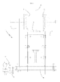
- 1 shows as a whole a segment of a continuous conveyor with the side guide adjustment system object of the invention.
- 2 shows the conveyor having, in this example, two rectilinear orthogonal segments joined by a curvilinear segment.
- FIG. 3 shows the conveying side guides, located one in front of the other with respect to a centre line 4 of the conveyor 2.
- the purpose of the guides is to keep stable the articles by promoting their transport.
- a plurality of devices, generally indicated at 5 are located along said conveyor 2 to enable a format change, that is, a width adjustment, with respect to the centre line 4, of the guides 3.
- Said device 5 approaches or moves away two vertical facing rods 6 integral, at their upper ends, to said guides 3.
- Each vertical rod 6 is in turn driven and supported by a second linear handling means, that is, a second rod 16, arranged below and substantially orthogonal to the conveyor 2. While an end is integral to the rod 6, the other end is hinged to arms 7A and 7B of a substantially "T"-shaped compensator 7, the segment 7C of the "T" being opposite to the conveyor 2, so that said arms 7A and 7B are adjacent the conveyor.
- a second linear handling means that is, a second rod 16 arranged below and substantially orthogonal to the conveyor 2. While an end is integral to the rod 6, the other end is hinged to arms 7A and 7B of a substantially "T"-shaped compensator 7, the segment 7C of the "T" being opposite to the conveyor 2, so that said arms 7A and 7B are adjacent the conveyor.
- Said compensator 7 is hinged to a stationary structure 8 in turn integral to the conveyor 2, and located on the same side.
- said compensator 7 can rotate with respect to a vertical rotation axis: precisely, said rotation centre C is on the median axis of the "T" and at the intersection of the arms 7A and 7B.
- the compensator can be located with the segment 7C perfectly orthogonal to the conveyor, as shown in Figure 3 , or rotated with a varying tilt, as shown in Figures 4 and 5 .
- Figure 5 an arm approaches the conveyor while the other arm moves away and since one of the two arms, by passing under the conveyor 2, is integral, by means of the rod 6, to the guide 3 on the other side, it follows that both guides 3 move according to an opening or closing direction with respect to the centre line 4 of the conveyor 2.
- the system can advantageously obtain in this way a quick adjustment of the guides.
- the system of the invention can electromechanically drive more devices 5 located along the conveyor, as shown in Figure 1 .
- a pin 9 freely rotating with respect to its axis 9B which can cause the compensator 7 rotation by the thrust or traction exerted by a bar 10 substantially orthogonal to the rod 7C and generating the moment necessary with the arm 7C adapted to rotate the system with respect to the rotation centre C.
- Said bar 10 is inserted in a corresponding hole 9A of the pin 9 and it is fixed to it.
- the bar 10 is stiff along the linear segment of the conveyor 2 and connects a plurality of devices 5, while along the curvilinear segments (see Figure 1 ), the bar 10 extends integrally with a flexible cable 13 enabling to divide the curve in several segments while it is engaged integrally to the pins 9 of the corresponding devices 5.
- said bar 10 acts as a stiff cable.
- the bar 10 and/or the flexible cable 13 connect and drive the devices 5 located on the same side.
- the cable defined by joining different stiff cables 10 and flexible cables 13 is displaced by means 11 and 12 connected at the ends indicated at 14 and 15; precisely, the means are a linear actuator 11 and an air cylinder 12.
- the actuator 11 is the element which pushes or pulls the cable, and it is also connected to a position transducer in order to track the imparted displacement in order to compute the compensator 7 rotation angle and the opening or closing variation of the guides 3.
- the air cylinder 13 mainly has the function of keeping taut the one or more flexible cables 13 possibly present and located along the curvilinear segments of the conveyor 2.
- 100 indicates, as a whole, a portion of a group for conveying objects formed now by a series of parallel conveyors 2 and adjustable by the side guide adjustment system object of the invention.
- each conveyor 2 is provided with conveying side guides 3, each of them being located one in front of the other with respect to the centre line 4 of the conveyor 2.
- the device 5 drives the vertical and facing rods 6 to approach them or to move them away, said rods 6 being integral with said guides 3; the rods 6 being in turn driven and supported by two rods 16; obviously in the present example, which can be defined multiple conveyors, the rods 16 have a length suitable to displace also the rods 6 of the farther conveyors 2.
- the two rods 16 are hinged to the arms 7A and 7B of the "T"-shaped compensator 7 and located with the segment 7C of the "T" opposite with respect to the conveyor 2, so that said arms 7A and 7B are adjacent the conveyor.
- Said bar 10 is inserted in a corresponding hole of the pin 9 and is fixed to it.
Landscapes
- Engineering & Computer Science (AREA)
- Mechanical Engineering (AREA)
- Framework For Endless Conveyors (AREA)
- Attitude Control For Articles On Conveyors (AREA)
- Loading Or Unloading Of Vehicles (AREA)
- Intermediate Stations On Conveyors (AREA)
- Platform Screen Doors And Railroad Systems (AREA)
Abstract
Description
- The present invention refers to the field of conveying systems and, more specifically, refers to a system for adjusting the side facing guides of continuous conveyors.
- The side conveying guides of articles conveyors of different types are known, their purpose is to promote the transport and to keep the correct position of the articles.
- In order to handle articles of different sizes or volumes or shapes, it is also known the use of format changing systems for adjusting the guides which, substantially, approach or move away said side guides one from the other for adjusting their available flow cross-section.
- Said systems having adjustable guides are used in several fields, for example, in bottling, packaging lines, etc.
- A good system having adjustable guides has many problems difficult to solve: on the one hand, the adjustment must be accurate without clamping the article, on the other hand, it is necessary to maintain constant, along the transport line, the widths between the facing guides. Further, since it is very common a change of size of the articles to be conveyed, it is essential to quickly adjust the system to different sizes.
- Some adjustment systems are still of the manual type, that is, for performing an accommodation, an operator rotates adjustment knobs or worms in order to manually guide in the desired position said side guides. It is apparent that said systems do not offer a quick adjustment because usually said systems are distributed along the line and therefore their adjustment requires the operator to physically walk along each segment to manually orient and adjust the width between the facing guides and repeat this procedure for each section. Moreover, sometimes this procedure must be repeated on both sides of the conveyor belt.
- Instead, other adjustment systems are automatic and use mechanical transmission systems for controlling one ore more conveyor sections and also, sometimes, both the side guides by one operation.
- The present invention belongs to the latter type of adjustment systems.
- Object of the present invention is to provide a system for adjusting the side guides of conveyors which can be quickly adapted to accommodate containers of different sizes.
- The system, object of the present invention, is characterized by the following claims.
- This and other characteristics will be better understood by the following description of some embodiments illustratively shown in a non-limiting way in the attached drawings:
-
Figure 1 is a plan view of a segment of the conveyor with the guide adjustment system, object of the invention, -
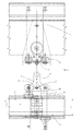
Figure 2 is a front view of the device ofFigure 1 , -
Figure 3 is a plan view, -
Figure 4 is a plan view of the adjusting device operated to approach facing side guides, -
Figure 5 is a plan view with the adjusting device operated to move away the facing side guides, -
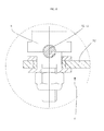
Figure 6 is a portion of a pin for fixing a drive rod or cable, -
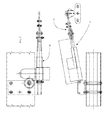
Figure 7 is a detail of the handling actuator, located at one end of the cable operating the system, -
Figure 8 is a detail of the air cylinder for adjusting the tightness of the flexible cable, located at the other end of the operating cable, -
Figure 9 shows a variant of the side guide adjustment system of conveyors, comprising now more rows of conveyors and guides, which can be driven to be opened and closed by the system of the invention, -
Figure 10 is a front cross-section of the device ofFigure 9 . - Particularly referring to
Figures 1 and2 , 1 shows as a whole a segment of a continuous conveyor with the side guide adjustment system object of the invention. 2 shows the conveyor having, in this example, two rectilinear orthogonal segments joined by a curvilinear segment. - 3 shows the conveying side guides, located one in front of the other with respect to a centre line 4 of the
conveyor 2. As said before, the purpose of the guides is to keep stable the articles by promoting their transport. In order to handle articles of different sizes and/or shapes, a plurality of devices, generally indicated at 5, are located along saidconveyor 2 to enable a format change, that is, a width adjustment, with respect to the centre line 4, of theguides 3. Saiddevice 5 approaches or moves away two vertical facingrods 6 integral, at their upper ends, to saidguides 3. - Each
vertical rod 6 is in turn driven and supported by a second linear handling means, that is, asecond rod 16, arranged below and substantially orthogonal to theconveyor 2. While an end is integral to therod 6, the other end is hinged toarms 7A and 7B of a substantially "T"-shaped compensator 7, thesegment 7C of the "T" being opposite to theconveyor 2, so that saidarms 7A and 7B are adjacent the conveyor. - Said
compensator 7 is hinged to astationary structure 8 in turn integral to theconveyor 2, and located on the same side. In this way saidcompensator 7 can rotate with respect to a vertical rotation axis: precisely, said rotation centre C is on the median axis of the "T" and at the intersection of thearms 7A and 7B. - It follows that the compensator can be located with the
segment 7C perfectly orthogonal to the conveyor, as shown inFigure 3 , or rotated with a varying tilt, as shown inFigures 4 and 5 . For the latter arrangement,Figure 5 , an arm approaches the conveyor while the other arm moves away and since one of the two arms, by passing under theconveyor 2, is integral, by means of therod 6, to theguide 3 on the other side, it follows that bothguides 3 move according to an opening or closing direction with respect to the centre line 4 of theconveyor 2. - The system can advantageously obtain in this way a quick adjustment of the guides.
- For obtaining a quicker adjustment, the system of the invention can electromechanically drive
more devices 5 located along the conveyor, as shown inFigure 1 . - To this end, adjacent the end defined by the
segment 7C of thecompensator 7, there is a hole in which it is fixed apin 9 freely rotating with respect to its axis 9B which can cause thecompensator 7 rotation by the thrust or traction exerted by abar 10 substantially orthogonal to therod 7C and generating the moment necessary with thearm 7C adapted to rotate the system with respect to the rotation centre C. - Said
bar 10 is inserted in a corresponding hole 9A of thepin 9 and it is fixed to it. - The
bar 10 is stiff along the linear segment of theconveyor 2 and connects a plurality ofdevices 5, while along the curvilinear segments (seeFigure 1 ), thebar 10 extends integrally with aflexible cable 13 enabling to divide the curve in several segments while it is engaged integrally to thepins 9 of thecorresponding devices 5. - Substantially, said
bar 10 acts as a stiff cable. Anyway, thebar 10 and/or theflexible cable 13 connect and drive thedevices 5 located on the same side. - Generally, the cable defined by joining different
stiff cables 10 andflexible cables 13 is displaced bymeans linear actuator 11 and anair cylinder 12. - The
actuator 11 is the element which pushes or pulls the cable, and it is also connected to a position transducer in order to track the imparted displacement in order to compute thecompensator 7 rotation angle and the opening or closing variation of theguides 3. - The
air cylinder 13 mainly has the function of keeping taut the one or moreflexible cables 13 possibly present and located along the curvilinear segments of theconveyor 2. - Referring particularly to
Figures 9 and10 , 100 indicates, as a whole, a portion of a group for conveying objects formed now by a series ofparallel conveyors 2 and adjustable by the side guide adjustment system object of the invention. - It is to be observed that each
conveyor 2 is provided with conveyingside guides 3, each of them being located one in front of the other with respect to the centre line 4 of theconveyor 2. - It is to be observed that at the side of one of the
conveyors 2, there are a plurality ofdevices 5 for adjusting the width, with respect to the centre line 4, of all theguides 3. - Indeed, the
device 5 drives the vertical and facingrods 6 to approach them or to move them away, saidrods 6 being integral withsaid guides 3; therods 6 being in turn driven and supported by tworods 16; obviously in the present example, which can be defined multiple conveyors, therods 16 have a length suitable to displace also therods 6 of the fartherconveyors 2. - As before, the two
rods 16 are hinged to thearms 7A and 7B of the "T"-shaped compensator 7 and located with thesegment 7C of the "T" opposite with respect to theconveyor 2, so that saidarms 7A and 7B are adjacent the conveyor. - Adjacent the end defined by the
segment 7C of thecompensator 7 there is a hole in which is fixed apin 9 freely rotating with respect to its axis 9B but which can cause the rotation of thecompensator 7 by the thrust or traction exerted by abar 10 substantially arranged orthogonal to therod 7C and generating the moment necessary by thearm 7C adapted to rotate the system with respect to the rotation centre C. - Said
bar 10 is inserted in a corresponding hole of thepin 9 and is fixed to it.
Claims (2)
- System for adjusting side guides (3) of conveyors (2), said conveyors comprising longitudinal sections and/or connecting curved sections, said side guides (3) facing each other with respect to its centre line (4), said system comprising a plurality of devices (5) for adjusting the distance between facing guides (3), which drive, by a compensator (7), vertical rods (6) reciprocally departing or approaching, said rods (6) being integral with said guides (3); said compensator (7) being capable of rotating around a vertical rotation axis, wherein said rotation centre (C) is positioned on the compensator (7) axis and at the intersection of its two arms (7A) and (7B), characterized by the fact that said one or more devices (5) are driven by a cable formed by one or more stiff strands (10) and /or one or more flexible strands (13) reciprocally integral and linearly moved by a linear actuator (11) and a pneumatic cylinder (12) connected to the ends (14) and (15) of the cable and being:a. the actuator (11), the element in charge of pushing or pulling the cable, being also connected to a position transducer,b. the pneumatic cylinder (13), the element in charge of maintaining stretched the one or more flexible strands (13), if they are present and arranged along the conveyor (2) curved sections.
- System according to claim 1, characterized by the fact the stiff strands (10) and/or the one or more flexible strands (13) connect and drive the devices (5) positioned on the same side.
Applications Claiming Priority (1)
| Application Number | Priority Date | Filing Date | Title |
|---|---|---|---|
| ITPR2010A000010A IT1397947B1 (en) | 2010-02-09 | 2010-02-09 | ADJUSTMENT SYSTEM FOR SIDE TRUCK GUIDES |
Publications (2)
| Publication Number | Publication Date |
|---|---|
| EP2354050A1 true EP2354050A1 (en) | 2011-08-10 |
| EP2354050B1 EP2354050B1 (en) | 2012-09-19 |
Family
ID=42775856
Family Applications (1)
| Application Number | Title | Priority Date | Filing Date |
|---|---|---|---|
| EP20110152858 Active EP2354050B1 (en) | 2010-02-09 | 2011-02-01 | System for adjusting the side facing guides of conveyors |
Country Status (2)
| Country | Link |
|---|---|
| EP (1) | EP2354050B1 (en) |
| IT (1) | IT1397947B1 (en) |
Cited By (1)
| Publication number | Priority date | Publication date | Assignee | Title |
|---|---|---|---|---|
| CN112047023A (en) * | 2019-06-05 | 2020-12-08 | 克罗内斯股份公司 | Device for adjusting the guide width of a conveyor |
Citations (1)
| Publication number | Priority date | Publication date | Assignee | Title |
|---|---|---|---|---|
| EP1840051A1 (en) * | 2006-03-29 | 2007-10-03 | Transmisiones Mecánicas AVE, S.A. | Adjustable guide rail |
-
2010
- 2010-02-09 IT ITPR2010A000010A patent/IT1397947B1/en active
-
2011
- 2011-02-01 EP EP20110152858 patent/EP2354050B1/en active Active
Patent Citations (1)
| Publication number | Priority date | Publication date | Assignee | Title |
|---|---|---|---|---|
| EP1840051A1 (en) * | 2006-03-29 | 2007-10-03 | Transmisiones Mecánicas AVE, S.A. | Adjustable guide rail |
Cited By (3)
| Publication number | Priority date | Publication date | Assignee | Title |
|---|---|---|---|---|
| CN112047023A (en) * | 2019-06-05 | 2020-12-08 | 克罗内斯股份公司 | Device for adjusting the guide width of a conveyor |
| EP3747806A1 (en) * | 2019-06-05 | 2020-12-09 | Krones Ag | Device for adjusting a guide width of a conveyor |
| US11358799B2 (en) | 2019-06-05 | 2022-06-14 | Krones Ag | Device for adjusting a guide width of a conveyor |
Also Published As
| Publication number | Publication date |
|---|---|
| ITPR20100010A1 (en) | 2011-08-10 |
| IT1397947B1 (en) | 2013-02-04 |
| EP2354050B1 (en) | 2012-09-19 |
Similar Documents
| Publication | Publication Date | Title |
|---|---|---|
| CN101306762B (en) | Switches for product supply lines | |
| US11787645B2 (en) | Conveyor device for conveying flexible containers along a packaging line | |
| AU2009311204B2 (en) | Apparatus and method for compiling flat objects | |
| US9216862B2 (en) | Narrow belt sorter | |
| CN202156564U (en) | Laned grabbing counting conveying device | |
| US8628131B2 (en) | Product gripper system | |
| US9828186B2 (en) | Adjustable guide rail system for conveyors | |
| BR102012001259A2 (en) | DEVICE AND PROCESS FOR RECEIVING, RETENTION AND / OR HANDLING OF FLAT OBJECTS | |
| US9321593B2 (en) | Flexible package transport device for packaging machines | |
| BRPI0712288A2 (en) | device for the treatment of flexible tubular structures with at least one orifice | |
| EP1044149B1 (en) | Conveyor including controlled package ejection capabilities | |
| EP2354050B1 (en) | System for adjusting the side facing guides of conveyors | |
| US6854586B1 (en) | Unstable article conveying device with diverter having curved path | |
| ES3037153T3 (en) | Item manipulator | |
| EP2253215A1 (en) | Device and method for twisting elongated dough strips | |
| EP2942298B1 (en) | Line-changing device for an automatic horizontal flexible container forming and filling machine | |
| CN108263674A (en) | A kind of manipulator for bottling machine and the bottling machine with the manipulator | |
| ES2341056T3 (en) | DEVICE FOR RECEIVING AND TRANSPORTING A PRODUCT. | |
| ES3064267T3 (en) | A gripper and a method of using a robot with the gripper | |
| CN107244386A (en) | A kind of receipts anchor device of anchor winch | |
| US8376348B2 (en) | Device and method for the transfer of flexible, elongate objects | |
| US20070095247A1 (en) | Guide positioning system for a container transport line | |
| US12145761B2 (en) | Packaging line | |
| EP2609809B1 (en) | Transfer device with split conveyor means | |
| CN110482263B (en) | Cargo transferring device and loading and unloading equipment |
Legal Events
| Date | Code | Title | Description |
|---|---|---|---|
| PUAI | Public reference made under article 153(3) epc to a published international application that has entered the european phase |
Free format text: ORIGINAL CODE: 0009012 |
|
| AK | Designated contracting states |
Kind code of ref document: A1 Designated state(s): AL AT BE BG CH CY CZ DE DK EE ES FI FR GB GR HR HU IE IS IT LI LT LU LV MC MK MT NL NO PL PT RO RS SE SI SK SM TR |
|
| AX | Request for extension of the european patent |
Extension state: BA ME |
|
| 17P | Request for examination filed |
Effective date: 20120131 |
|
| RIC1 | Information provided on ipc code assigned before grant |
Ipc: B65G 21/20 20060101AFI20120227BHEP |
|
| GRAP | Despatch of communication of intention to grant a patent |
Free format text: ORIGINAL CODE: EPIDOSNIGR1 |
|
| GRAS | Grant fee paid |
Free format text: ORIGINAL CODE: EPIDOSNIGR3 |
|
| GRAA | (expected) grant |
Free format text: ORIGINAL CODE: 0009210 |
|
| AK | Designated contracting states |
Kind code of ref document: B1 Designated state(s): AL AT BE BG CH CY CZ DE DK EE ES FI FR GB GR HR HU IE IS IT LI LT LU LV MC MK MT NL NO PL PT RO RS SE SI SK SM TR |
|
| REG | Reference to a national code |
Ref country code: GB Ref legal event code: FG4D |
|
| REG | Reference to a national code |
Ref country code: CH Ref legal event code: EP |
|
| REG | Reference to a national code |
Ref country code: IE Ref legal event code: FG4D |
|
| REG | Reference to a national code |
Ref country code: AT Ref legal event code: REF Ref document number: 575891 Country of ref document: AT Kind code of ref document: T Effective date: 20121015 |
|
| REG | Reference to a national code |
Ref country code: DE Ref legal event code: R096 Ref document number: 602011000222 Country of ref document: DE Effective date: 20121115 |
|
| PG25 | Lapsed in a contracting state [announced via postgrant information from national office to epo] |
Ref country code: NO Free format text: LAPSE BECAUSE OF FAILURE TO SUBMIT A TRANSLATION OF THE DESCRIPTION OR TO PAY THE FEE WITHIN THE PRESCRIBED TIME-LIMIT Effective date: 20121219 Ref country code: FI Free format text: LAPSE BECAUSE OF FAILURE TO SUBMIT A TRANSLATION OF THE DESCRIPTION OR TO PAY THE FEE WITHIN THE PRESCRIBED TIME-LIMIT Effective date: 20120919 Ref country code: LT Free format text: LAPSE BECAUSE OF FAILURE TO SUBMIT A TRANSLATION OF THE DESCRIPTION OR TO PAY THE FEE WITHIN THE PRESCRIBED TIME-LIMIT Effective date: 20120919 Ref country code: HR Free format text: LAPSE BECAUSE OF FAILURE TO SUBMIT A TRANSLATION OF THE DESCRIPTION OR TO PAY THE FEE WITHIN THE PRESCRIBED TIME-LIMIT Effective date: 20120919 |
|
| REG | Reference to a national code |
Ref country code: NL Ref legal event code: VDEP Effective date: 20120919 |
|
| REG | Reference to a national code |
Ref country code: AT Ref legal event code: MK05 Ref document number: 575891 Country of ref document: AT Kind code of ref document: T Effective date: 20120919 |
|
| REG | Reference to a national code |
Ref country code: LT Ref legal event code: MG4D Effective date: 20120919 |
|
| PG25 | Lapsed in a contracting state [announced via postgrant information from national office to epo] |
Ref country code: GR Free format text: LAPSE BECAUSE OF FAILURE TO SUBMIT A TRANSLATION OF THE DESCRIPTION OR TO PAY THE FEE WITHIN THE PRESCRIBED TIME-LIMIT Effective date: 20121220 Ref country code: SE Free format text: LAPSE BECAUSE OF FAILURE TO SUBMIT A TRANSLATION OF THE DESCRIPTION OR TO PAY THE FEE WITHIN THE PRESCRIBED TIME-LIMIT Effective date: 20120919 Ref country code: LV Free format text: LAPSE BECAUSE OF FAILURE TO SUBMIT A TRANSLATION OF THE DESCRIPTION OR TO PAY THE FEE WITHIN THE PRESCRIBED TIME-LIMIT Effective date: 20120919 Ref country code: SI Free format text: LAPSE BECAUSE OF FAILURE TO SUBMIT A TRANSLATION OF THE DESCRIPTION OR TO PAY THE FEE WITHIN THE PRESCRIBED TIME-LIMIT Effective date: 20120919 |
|
| PG25 | Lapsed in a contracting state [announced via postgrant information from national office to epo] |
Ref country code: RO Free format text: LAPSE BECAUSE OF FAILURE TO SUBMIT A TRANSLATION OF THE DESCRIPTION OR TO PAY THE FEE WITHIN THE PRESCRIBED TIME-LIMIT Effective date: 20120919 Ref country code: EE Free format text: LAPSE BECAUSE OF FAILURE TO SUBMIT A TRANSLATION OF THE DESCRIPTION OR TO PAY THE FEE WITHIN THE PRESCRIBED TIME-LIMIT Effective date: 20120919 Ref country code: NL Free format text: LAPSE BECAUSE OF FAILURE TO SUBMIT A TRANSLATION OF THE DESCRIPTION OR TO PAY THE FEE WITHIN THE PRESCRIBED TIME-LIMIT Effective date: 20120919 Ref country code: IS Free format text: LAPSE BECAUSE OF FAILURE TO SUBMIT A TRANSLATION OF THE DESCRIPTION OR TO PAY THE FEE WITHIN THE PRESCRIBED TIME-LIMIT Effective date: 20130119 Ref country code: CZ Free format text: LAPSE BECAUSE OF FAILURE TO SUBMIT A TRANSLATION OF THE DESCRIPTION OR TO PAY THE FEE WITHIN THE PRESCRIBED TIME-LIMIT Effective date: 20120919 Ref country code: BE Free format text: LAPSE BECAUSE OF FAILURE TO SUBMIT A TRANSLATION OF THE DESCRIPTION OR TO PAY THE FEE WITHIN THE PRESCRIBED TIME-LIMIT Effective date: 20120919 |
|
| PG25 | Lapsed in a contracting state [announced via postgrant information from national office to epo] |
Ref country code: PT Free format text: LAPSE BECAUSE OF FAILURE TO SUBMIT A TRANSLATION OF THE DESCRIPTION OR TO PAY THE FEE WITHIN THE PRESCRIBED TIME-LIMIT Effective date: 20130121 Ref country code: PL Free format text: LAPSE BECAUSE OF FAILURE TO SUBMIT A TRANSLATION OF THE DESCRIPTION OR TO PAY THE FEE WITHIN THE PRESCRIBED TIME-LIMIT Effective date: 20120919 Ref country code: SK Free format text: LAPSE BECAUSE OF FAILURE TO SUBMIT A TRANSLATION OF THE DESCRIPTION OR TO PAY THE FEE WITHIN THE PRESCRIBED TIME-LIMIT Effective date: 20120919 |
|
| PG25 | Lapsed in a contracting state [announced via postgrant information from national office to epo] |
Ref country code: AT Free format text: LAPSE BECAUSE OF FAILURE TO SUBMIT A TRANSLATION OF THE DESCRIPTION OR TO PAY THE FEE WITHIN THE PRESCRIBED TIME-LIMIT Effective date: 20120919 |
|
| PLBE | No opposition filed within time limit |
Free format text: ORIGINAL CODE: 0009261 |
|
| STAA | Information on the status of an ep patent application or granted ep patent |
Free format text: STATUS: NO OPPOSITION FILED WITHIN TIME LIMIT |
|
| PG25 | Lapsed in a contracting state [announced via postgrant information from national office to epo] |
Ref country code: BG Free format text: LAPSE BECAUSE OF FAILURE TO SUBMIT A TRANSLATION OF THE DESCRIPTION OR TO PAY THE FEE WITHIN THE PRESCRIBED TIME-LIMIT Effective date: 20121219 Ref country code: DK Free format text: LAPSE BECAUSE OF FAILURE TO SUBMIT A TRANSLATION OF THE DESCRIPTION OR TO PAY THE FEE WITHIN THE PRESCRIBED TIME-LIMIT Effective date: 20120919 Ref country code: RS Free format text: LAPSE BECAUSE OF FAILURE TO SUBMIT A TRANSLATION OF THE DESCRIPTION OR TO PAY THE FEE WITHIN THE PRESCRIBED TIME-LIMIT Effective date: 20120919 |
|
| 26N | No opposition filed |
Effective date: 20130620 |
|
| PG25 | Lapsed in a contracting state [announced via postgrant information from national office to epo] |
Ref country code: MC Free format text: LAPSE BECAUSE OF NON-PAYMENT OF DUE FEES Effective date: 20130228 |
|
| REG | Reference to a national code |
Ref country code: DE Ref legal event code: R097 Ref document number: 602011000222 Country of ref document: DE Effective date: 20130620 |
|
| PG25 | Lapsed in a contracting state [announced via postgrant information from national office to epo] |
Ref country code: ES Free format text: LAPSE BECAUSE OF FAILURE TO SUBMIT A TRANSLATION OF THE DESCRIPTION OR TO PAY THE FEE WITHIN THE PRESCRIBED TIME-LIMIT Effective date: 20121230 |
|
| PG25 | Lapsed in a contracting state [announced via postgrant information from national office to epo] |
Ref country code: CY Free format text: LAPSE BECAUSE OF FAILURE TO SUBMIT A TRANSLATION OF THE DESCRIPTION OR TO PAY THE FEE WITHIN THE PRESCRIBED TIME-LIMIT Effective date: 20120919 |
|
| REG | Reference to a national code |
Ref country code: IE Ref legal event code: MM4A |
|
| PG25 | Lapsed in a contracting state [announced via postgrant information from national office to epo] |
Ref country code: IE Free format text: LAPSE BECAUSE OF NON-PAYMENT OF DUE FEES Effective date: 20130201 Ref country code: AL Free format text: LAPSE BECAUSE OF FAILURE TO SUBMIT A TRANSLATION OF THE DESCRIPTION OR TO PAY THE FEE WITHIN THE PRESCRIBED TIME-LIMIT Effective date: 20120919 |
|
| PG25 | Lapsed in a contracting state [announced via postgrant information from national office to epo] |
Ref country code: MT Free format text: LAPSE BECAUSE OF FAILURE TO SUBMIT A TRANSLATION OF THE DESCRIPTION OR TO PAY THE FEE WITHIN THE PRESCRIBED TIME-LIMIT Effective date: 20120919 |
|
| REG | Reference to a national code |
Ref country code: CH Ref legal event code: PL |
|
| PG25 | Lapsed in a contracting state [announced via postgrant information from national office to epo] |
Ref country code: LI Free format text: LAPSE BECAUSE OF NON-PAYMENT OF DUE FEES Effective date: 20140228 Ref country code: CH Free format text: LAPSE BECAUSE OF NON-PAYMENT OF DUE FEES Effective date: 20140228 |
|
| PG25 | Lapsed in a contracting state [announced via postgrant information from national office to epo] |
Ref country code: SM Free format text: LAPSE BECAUSE OF FAILURE TO SUBMIT A TRANSLATION OF THE DESCRIPTION OR TO PAY THE FEE WITHIN THE PRESCRIBED TIME-LIMIT Effective date: 20120919 |
|
| PG25 | Lapsed in a contracting state [announced via postgrant information from national office to epo] |
Ref country code: TR Free format text: LAPSE BECAUSE OF FAILURE TO SUBMIT A TRANSLATION OF THE DESCRIPTION OR TO PAY THE FEE WITHIN THE PRESCRIBED TIME-LIMIT Effective date: 20120919 |
|
| PG25 | Lapsed in a contracting state [announced via postgrant information from national office to epo] |
Ref country code: LU Free format text: LAPSE BECAUSE OF NON-PAYMENT OF DUE FEES Effective date: 20130201 Ref country code: HU Free format text: LAPSE BECAUSE OF FAILURE TO SUBMIT A TRANSLATION OF THE DESCRIPTION OR TO PAY THE FEE WITHIN THE PRESCRIBED TIME-LIMIT; INVALID AB INITIO Effective date: 20110201 Ref country code: MK Free format text: LAPSE BECAUSE OF FAILURE TO SUBMIT A TRANSLATION OF THE DESCRIPTION OR TO PAY THE FEE WITHIN THE PRESCRIBED TIME-LIMIT Effective date: 20120919 |
|
| REG | Reference to a national code |
Ref country code: FR Ref legal event code: PLFP Year of fee payment: 6 |
|
| REG | Reference to a national code |
Ref country code: FR Ref legal event code: PLFP Year of fee payment: 7 |
|
| REG | Reference to a national code |
Ref country code: FR Ref legal event code: PLFP Year of fee payment: 8 |
|
| P01 | Opt-out of the competence of the unified patent court (upc) registered |
Effective date: 20230622 |
|
| PGFP | Annual fee paid to national office [announced via postgrant information from national office to epo] |
Ref country code: GB Payment date: 20260223 Year of fee payment: 16 |
|
| PGFP | Annual fee paid to national office [announced via postgrant information from national office to epo] |
Ref country code: DE Payment date: 20260220 Year of fee payment: 16 |
|
| PGFP | Annual fee paid to national office [announced via postgrant information from national office to epo] |
Ref country code: IT Payment date: 20260203 Year of fee payment: 16 |
|
| PGFP | Annual fee paid to national office [announced via postgrant information from national office to epo] |
Ref country code: FR Payment date: 20260227 Year of fee payment: 16 |