EP2353985B1 - Brake system for reduced aerodynamic drag - Google Patents
Brake system for reduced aerodynamic drag Download PDFInfo
- Publication number
- EP2353985B1 EP2353985B1 EP11152539.0A EP11152539A EP2353985B1 EP 2353985 B1 EP2353985 B1 EP 2353985B1 EP 11152539 A EP11152539 A EP 11152539A EP 2353985 B1 EP2353985 B1 EP 2353985B1
- Authority
- EP
- European Patent Office
- Prior art keywords
- brake arms
- front fork
- legs
- aerodynamic
- brake
- Prior art date
- Legal status (The legal status is an assumption and is not a legal conclusion. Google has not performed a legal analysis and makes no representation as to the accuracy of the status listed.)
- Not-in-force
Links
Images



Classifications
-
- B—PERFORMING OPERATIONS; TRANSPORTING
- B62—LAND VEHICLES FOR TRAVELLING OTHERWISE THAN ON RAILS
- B62K—CYCLES; CYCLE FRAMES; CYCLE STEERING DEVICES; RIDER-OPERATED TERMINAL CONTROLS SPECIALLY ADAPTED FOR CYCLES; CYCLE AXLE SUSPENSIONS; CYCLE SIDECARS, FORECARS, OR THE LIKE
- B62K19/00—Cycle frames
- B62K19/30—Frame parts shaped to receive other cycle parts or accessories
- B62K19/38—Frame parts shaped to receive other cycle parts or accessories for attaching brake members
-
- B—PERFORMING OPERATIONS; TRANSPORTING
- B62—LAND VEHICLES FOR TRAVELLING OTHERWISE THAN ON RAILS
- B62J—CYCLE SADDLES OR SEATS; AUXILIARY DEVICES OR ACCESSORIES SPECIALLY ADAPTED TO CYCLES AND NOT OTHERWISE PROVIDED FOR, e.g. ARTICLE CARRIERS OR CYCLE PROTECTORS
- B62J11/00—Supporting arrangements specially adapted for fastening specific devices to cycles, e.g. supports for attaching maps
- B62J11/10—Supporting arrangements specially adapted for fastening specific devices to cycles, e.g. supports for attaching maps for mechanical cables, hoses, pipes or electric wires, e.g. cable guides
- B62J11/13—Supporting arrangements specially adapted for fastening specific devices to cycles, e.g. supports for attaching maps for mechanical cables, hoses, pipes or electric wires, e.g. cable guides specially adapted for mechanical cables
-
- B—PERFORMING OPERATIONS; TRANSPORTING
- B62—LAND VEHICLES FOR TRAVELLING OTHERWISE THAN ON RAILS
- B62K—CYCLES; CYCLE FRAMES; CYCLE STEERING DEVICES; RIDER-OPERATED TERMINAL CONTROLS SPECIALLY ADAPTED FOR CYCLES; CYCLE AXLE SUSPENSIONS; CYCLE SIDECARS, FORECARS, OR THE LIKE
- B62K21/00—Steering devices
- B62K21/02—Front wheel forks or equivalent, e.g. single tine
Definitions
- the present invention relates to a front fork for a bicycle.
- Document US2008035431 discloses a front fork on which the preamble of claim 1 is based.
- a front fork according to claim 1 is provided.
- a front fork 10 is shown with brake arms 12a, b that are integrated into the legs 14a, b of the front fork 10.
- the legs 14a, b and the brake arms 12a, b collectively have an aerodynamic shape (tear drop shape).
- the leading portion 15a, b of the brake arms 12a, b may have a curved surface to assist in reducing aerodynamic drag caused by air passing by the front fork 10.
- the curved surface promotes laminar flow of air.
- the front fork 10 may have recesses 44a, b in each of the legs 14a, b of the front fork 10.
- the recesses 44a, b are disposed immediately below a crown 46 of the front fork 10.
- the recesses 44a, b are tapered so that the bottom portions 48a, b of the recess 44 are deeper compared to the upper portions 50a, b of the recess 44.
- the front brake arms 12a, b are rotatably disposed within the recess 44 formed in the legs 14a, b.
- through holes 52a, b are formed in the brake arms 12a, b of the front brake 40.
- Bolts 54a, b may be used to secure the brake arms 12a, b to the legs 14a, b of the front fork 10. Also, the brake arms 12a, b may pivot about the bolt 54. Caps 56a, b may be attached (e.g., snapped) over the bolt head 58. The exterior surface of the cap 56 may have an aerodynamic shape to reduce aerodynamic drag.
- the brake arms 12a, b of the front brake 40 define the aerodynamic leading portions 15a, b. The leading portions 15a, b may have an aerodynamic shape.
- the leading portions 15a, b have a cross sectional curved shape so that the brake arms 12a, b and the legs 14a, b collectively form an aerodynamic tear drop shape, as shown in Figure 2A .
- the front brake arms 12a, b function both as brake arms 12a, b as well as a means to reduce aerodynamic drag caused by the front rim brake 40.
- FIG. 2 the cross sectional view of the leg 14a and the front brake arm 12a is shown.
- the air flow path 60 initially contacts the leading portion 15a to split the air flow 60 in two.
- the curvature of the leading portion 15a attempts to maintain laminar flow of the air flow 60.
- Rear edges of the front brake arm 12a may be aligned to rear edges 64a of the leg 14a of the front fork 10.
- the rear edge 62a may be aligned to the front edge 64a so that as the air flow 60 passes the transition 66 between the front brake arm 12a and the leg 14a, the air flow 60 maintains laminar flow. It is also contemplated that the front edge 62a may be offset to the outside of the rear edge 64a.
- a minute offset may prevent air flow 60 from hitting the front edge 64a of the leg 14a and prevent turbulence. As the air flow 60 continues onward, the air flow 60 flows on the leg 14a until it is rejoined to each other at the backside of the leg 14a.
- the depth of the upper portion 50a of the recess 44a may be shallower compared to the depth of the bottom portion 48a of the recess 44a.
- the purpose of this contour is to allow as much material in the crown 46 to provide as much structural stability to the crown 46 as possible.
- the backside 66a, b of the brake arms 12a, b may have a corresponding curvilinear configuration. Starting from holes 52, the backside 66a, b curves away from the leading portion 15a then curves back toward the leading portion 15a until the backside 66a, b approaches the actuation mounting point 68a, b.
- the brake arms 12a, b will interfere with the flow of air 60 flowing past the medial side of the brake arms 12a, b. This interference may cause turbulence. However, the turbulence during slowdown of the bicycle is of no consequence since increased drag is desireable during slowdown of the bicycle.
Landscapes
- Engineering & Computer Science (AREA)
- Mechanical Engineering (AREA)
- Braking Arrangements (AREA)
- Motorcycle And Bicycle Frame (AREA)
Description
- The present invention relates to a front fork for a bicycle.
- In time trial bicycles, reduction of aerodynamic drag is one area in which performance may be improved without any additional training. Prior art bicycles have been manufactured to have aerodynamic shapes. By way of example and not limitation, the frame may have an aerodynamic shape so as to reduce aerodynamic drag on the bicycle. Other areas of the bicycle have also been aerodynamically improved so as to reduce the overall aerodynamic coefficient of the bicycle. For example, the rims, the spokes, and the brakes.
- Accordingly, there is a need in the art for an improved aerodynamic bicycle. Document
US2008035431 discloses a front fork on which the preamble ofclaim 1 is based. - According to the present invention, a front fork according to
claim 1 is provided. - These and other features and advantages of the various embodiments disclosed herein will be better understood with respect to the following description and drawings, in which like numbers refer to like parts throughout, and in which:
-
Figure 1 is a perspective view of a fork with front brake; -
Figure 2 is a cross sectional view of a leg of the front fork and a brake arm of the front brake; -
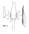
Figure 3 is a front view of a bottom bracket shell with a rear brake disposed behind the bottom bracket shell not forming part of the present invention; -
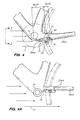
Figure 4 is a side view ofFigure 3 not forming part of thr present invention; -
Figure 4A is an alternate embodiment of the rear rim brake shown inFigure 4 ; -
Figure 5 is a perspective view of a front fork with a U-style rim brake not forming part of the present invention; -
Figure 5A is a cross sectional view of a leg and brake arm of the front fork and front U-style rim brake shown inFigure 5 not forming part of the present invention; -
Figure 6 is a perspective view of a front disc brake system not forming part of the present invention; -
Figure 7 is a perspective view of a rear disc brake system not forming part of the present invention; -
Figure 8 is a side view of a bicycle with internally routed cable or hydraulic lines for actuating rim brakes not forming part of the present invention; and -
Figure 9 is a side view of a bicycle with internally routed cable or hydraulic lines for actuating disc brakes not forming part of the present invention. - Referring now to
Figure 1 , afront fork 10 is shown withbrake arms 12a, b that are integrated into the legs 14a, b of thefront fork 10. The legs 14a, b and thebrake arms 12a, b collectively have an aerodynamic shape (tear drop shape). The leading portion 15a, b of thebrake arms 12a, b may have a curved surface to assist in reducing aerodynamic drag caused by air passing by thefront fork 10. The curved surface promotes laminar flow of air. - More particularly, referring now to
Figure 1 , thefront fork 10 may have recesses 44a, b in each of the legs 14a, b of thefront fork 10. The recesses 44a, b are disposed immediately below acrown 46 of thefront fork 10. In order to maintain sufficient strength requirements of thecrown 46 of thefront fork 10, the recesses 44a, b are tapered so that thebottom portions 48a, b of the recess 44 are deeper compared to the upper portions 50a, b of the recess 44. Thefront brake arms 12a, b are rotatably disposed within the recess 44 formed in the legs 14a, b. In particular, through holes 52a, b are formed in thebrake arms 12a, b of thefront brake 40.Bolts 54a, b may be used to secure thebrake arms 12a, b to the legs 14a, b of thefront fork 10. Also, thebrake arms 12a, b may pivot about the bolt 54.Caps 56a, b may be attached (e.g., snapped) over thebolt head 58. The exterior surface of the cap 56 may have an aerodynamic shape to reduce aerodynamic drag. Thebrake arms 12a, b of thefront brake 40 define the aerodynamic leading portions 15a, b. The leading portions 15a, b may have an aerodynamic shape. According to the invention, the leading portions 15a, b have a cross sectional curved shape so that thebrake arms 12a, b and the legs 14a, b collectively form an aerodynamic tear drop shape, as shown inFigure 2A . Thefront brake arms 12a, b function both asbrake arms 12a, b as well as a means to reduce aerodynamic drag caused by thefront rim brake 40. - Referring now to
Figure 2 , the cross sectional view of the leg 14a and thefront brake arm 12a is shown. Theair flow path 60 initially contacts the leading portion 15a to split theair flow 60 in two. The curvature of the leading portion 15a attempts to maintain laminar flow of theair flow 60. Rear edges of thefront brake arm 12a may be aligned torear edges 64a of the leg 14a of thefront fork 10. Therear edge 62a may be aligned to thefront edge 64a so that as theair flow 60 passes thetransition 66 between thefront brake arm 12a and the leg 14a, theair flow 60 maintains laminar flow. It is also contemplated that thefront edge 62a may be offset to the outside of therear edge 64a. A minute offset may preventair flow 60 from hitting thefront edge 64a of the leg 14a and prevent turbulence. As theair flow 60 continues onward, theair flow 60 flows on the leg 14a until it is rejoined to each other at the backside of the leg 14a. - As stated above, the depth of the upper portion 50a of the recess 44a may be shallower compared to the depth of the
bottom portion 48a of the recess 44a. The purpose of this contour is to allow as much material in thecrown 46 to provide as much structural stability to thecrown 46 as possible. Preferably, also, the backside 66a, b of thebrake arms 12a, b may have a corresponding curvilinear configuration. Starting fromholes 52, the backside 66a, b curves away from the leading portion 15a then curves back toward the leading portion 15a until the backside 66a, b approaches theactuation mounting point 68a, b. When the backside 66a, b curves away from the leading portion 15a, additional material is added to thefront brake arm 12a to provide stiffness to thefront brake arm 12a. The stiffness prevents flexing during application of the braking force. Excessive flexing causes a delay in application of the braking force to the rim of thewheel 30. The backside 66a moves away from the leading portion 15a in the middle portion 70a then approaches the leading portion 15a in the upper portion 72a. Generally, upper portions 72a, b of thebrake arms 12a, b are thicker compared to middle portions 70a, b of thebrake arms 12a, b so that thebrake arms 12a, b are relatively stiff to provide for acceptable brake response times. - During actuation of the
front rim brake 40, thebrake arms 12a, b will interfere with the flow ofair 60 flowing past the medial side of thebrake arms 12a, b. This interference may cause turbulence. However, the turbulence during slowdown of the bicycle is of no consequence since increased drag is desireable during slowdown of the bicycle.
Claims (3)
- A front fork (10) having left and right legs comprising a cantilever brake, the front fork (10) comprising:left and right cantilever brake arms (12a, 12b) having an aerodynamic teardrop shape leading portion (15a, 15b); said brake arms (12a, 12b) comprising a lower portion, a middle portion (70a, 70b) and an upper portion (72a, 72b); wherein said lower portion comprises a hole (52a, 52b); and wherein said upper portion (72a, 72b) comprises a ring-shaped actuation mounting portion (68a, 68b);
anda front fork (10) having left and right legs (14a, b), each of the legs (14a, b) defining a leading edge and a trailing edge with an aerodynamic teardrop shape cross section, each of the legs (14a, b) having a recess (22) at a leading portion of the leg with the left and right cantilever brake arms (12a, b) disposed within the recesses (22) of the left and right legs (14a, b) wherein the exterior surfaces of the left and right cantilever brake arms (12a, 12b) and exterior surfaces of the left and right legs (14a, b) collectively have a teardrop aerodynamic cross sectional configuration;characterized in that
said aerodynamic teardrop shape leading portion (15a, 15b) of said left and right cantilever brake arms (12a, 12b) comprises said middle portion (70 a, 70b) of said brake arms (12a, 12b). - The front fork (10) of Claim 1 wherein the left and right cantilever brake arms (12a, 12b) are thicker at pivoting portions compared to said actuation portions (68a, 68b) of the left and right cantilever brake arms (12a, 12b) for providing additional stiffness to the left and right cantilever brake arms (12a, 12b).
- The front fork (10) of Claim 2 wherein the recesses (22) are shallower closer to a crown of the fork (10) for stiffening the crown of the fork (10).
Applications Claiming Priority (1)
| Application Number | Priority Date | Filing Date | Title |
|---|---|---|---|
| US12/695,960 US8079609B2 (en) | 2010-01-28 | 2010-01-28 | Aerodynamic brake system |
Publications (3)
| Publication Number | Publication Date |
|---|---|
| EP2353985A2 EP2353985A2 (en) | 2011-08-10 |
| EP2353985A3 EP2353985A3 (en) | 2012-11-28 |
| EP2353985B1 true EP2353985B1 (en) | 2014-10-22 |
Family
ID=43629147
Family Applications (2)
| Application Number | Title | Priority Date | Filing Date |
|---|---|---|---|
| EP11000598.0A Not-in-force EP2353984B1 (en) | 2010-01-28 | 2011-01-26 | Brake system for reduced aerodynamic drag |
| EP11152539.0A Not-in-force EP2353985B1 (en) | 2010-01-28 | 2011-01-28 | Brake system for reduced aerodynamic drag |
Family Applications Before (1)
| Application Number | Title | Priority Date | Filing Date |
|---|---|---|---|
| EP11000598.0A Not-in-force EP2353984B1 (en) | 2010-01-28 | 2011-01-26 | Brake system for reduced aerodynamic drag |
Country Status (3)
| Country | Link |
|---|---|
| US (2) | US8079609B2 (en) |
| EP (2) | EP2353984B1 (en) |
| ES (1) | ES2505540T3 (en) |
Families Citing this family (14)
| Publication number | Priority date | Publication date | Assignee | Title |
|---|---|---|---|---|
| CA2596762C (en) * | 2006-08-10 | 2014-06-10 | Philip White | Fork with integrated braking system |
| US8079609B2 (en) * | 2010-01-28 | 2011-12-20 | Felt Racing, Llc | Aerodynamic brake system |
| US9943746B2 (en) | 2010-02-26 | 2018-04-17 | The Holding Company, Llc | Protective headgear with impact diffusion |
| US8588806B2 (en) | 2010-02-26 | 2013-11-19 | Thl Holding Company, Llc | Wireless device and methods for use in a paging network |
| FR2977560B1 (en) * | 2011-07-08 | 2013-07-12 | Look Cycle Int | BICYCLE WHEEL BEARING ASSEMBLY WITH INTEGRATED BRAKE |
| DE202011103814U1 (en) * | 2011-07-29 | 2012-11-15 | Canyon Bicycles Gmbh | Twin Bridges bicycle fork |
| ITBO20120253A1 (en) * | 2012-05-08 | 2013-11-09 | Diamant S R L | BICYCLE FRAME |
| JP2014066788A (en) * | 2012-09-25 | 2014-04-17 | Sony Corp | Image display device, and image display system |
| US9457867B2 (en) | 2013-03-14 | 2016-10-04 | Specialized Bicycle Components, Inc. | Bicycle brake assembly |
| TWI565619B (en) * | 2015-03-19 | 2017-01-11 | 彥豪金屬工業股份有限公司 | A front fork structure for a bicycle |
| US20160332691A1 (en) * | 2015-05-15 | 2016-11-17 | Fox Factory, Inc. | Lightweight fork assembly |
| CN104973192A (en) * | 2015-07-21 | 2015-10-14 | 易路达自行车(天津)有限公司 | Rust-proof anti-collision single-stand-column mechanical brake front fork |
| FR3075157B1 (en) * | 2017-12-20 | 2024-10-04 | Time Sport Int Sas | STRUCTURAL ELEMENT OF A CYCLE EQUIPPED WITH A VIBRATION DAMPING DEVICE AND METHOD FOR PRODUCING SUCH AN ELEMENT |
| AU2020243821A1 (en) * | 2019-03-15 | 2021-11-11 | Timothy SOUTHALL | Disc brake caliper location on a rigid bicycle fork |
Family Cites Families (19)
| Publication number | Priority date | Publication date | Assignee | Title |
|---|---|---|---|---|
| US3931871A (en) * | 1969-08-12 | 1976-01-13 | Martin Thomas C | Disc brake, hub and wheel assembly |
| US4488761A (en) * | 1982-05-10 | 1984-12-18 | Harley-Davidson Motor Co., Inc. | Wheel disc brake |
| US4974864A (en) * | 1989-10-24 | 1990-12-04 | Joseph Giocastro | Bicycle frame post openings allowing cable entry and exit |
| JP2005053363A (en) * | 2003-08-05 | 2005-03-03 | Shimano Inc | Hollow structural component part bicycle |
| US5478100A (en) * | 1994-07-15 | 1995-12-26 | Huffy Corporation | Bicycle frame having thru the tube cable routing |
| US5564531A (en) * | 1995-11-03 | 1996-10-15 | Avid Enterprises, Inc. | Adjustable brake arm and shoe mount for a cycle brake |
| US5803207A (en) * | 1995-11-14 | 1998-09-08 | Nielsen; Peter M. | Brake assembly for a cycle |
| US5788254A (en) * | 1997-04-07 | 1998-08-04 | Davis; John | Pedal powered vehicle |
| US6308806B1 (en) * | 1999-09-13 | 2001-10-30 | Peter M. Nielsen | Brake assembly for a cycle |
| CA2462068A1 (en) * | 2003-03-26 | 2004-09-26 | John Chmider | A bicycle having internally routed control cables |
| TWM286174U (en) * | 2005-09-28 | 2006-01-21 | Shang-Ru Tsai | Bicycle frame structure capable of hiding brake |
| FR2903650A1 (en) * | 2006-07-17 | 2008-01-18 | Time Sport Internat Sa | BRAKE DEVICE FOR A WHEEL, IN PARTICULAR FOR A BICYCLE WHEEL |
| CA2596762C (en) * | 2006-08-10 | 2014-06-10 | Philip White | Fork with integrated braking system |
| US7614634B2 (en) * | 2007-04-13 | 2009-11-10 | Felt Racing, Llc | Aerodynamic time trial bike |
| US7878521B2 (en) * | 2007-04-16 | 2011-02-01 | Trek Bicycle Corporation | Bicycle frame with device cavity |
| DE102008020811A1 (en) * | 2008-04-25 | 2009-11-26 | Thomas Mertin | Rigid bicycle fork e.g. suspension fork, has two fork blades connected with fork shaft, and fastening units for fastening traction mechanism that causes elastic deformation of partially elastically deformable lever of blades |
| BE1018448A5 (en) * | 2008-06-16 | 2010-12-07 | Rp Beheer Nv | RING BRAKE SYSTEM FOR A BIKE. |
| US7854442B2 (en) * | 2008-08-29 | 2010-12-21 | Shimano Inc. | Bicycle wire holding arrangement |
| US8079609B2 (en) * | 2010-01-28 | 2011-12-20 | Felt Racing, Llc | Aerodynamic brake system |
-
2010
- 2010-01-28 US US12/695,960 patent/US8079609B2/en not_active Expired - Fee Related
-
2011
- 2011-01-26 ES ES11000598.0T patent/ES2505540T3/en active Active
- 2011-01-26 EP EP11000598.0A patent/EP2353984B1/en not_active Not-in-force
- 2011-01-28 EP EP11152539.0A patent/EP2353985B1/en not_active Not-in-force
- 2011-10-11 US US13/271,073 patent/US8356828B2/en not_active Expired - Fee Related
Also Published As
| Publication number | Publication date |
|---|---|
| US8079609B2 (en) | 2011-12-20 |
| ES2505540T3 (en) | 2014-10-10 |
| EP2353985A3 (en) | 2012-11-28 |
| US8356828B2 (en) | 2013-01-22 |
| US20120032413A1 (en) | 2012-02-09 |
| EP2353984A3 (en) | 2012-12-12 |
| EP2353985A2 (en) | 2011-08-10 |
| EP2353984A2 (en) | 2011-08-10 |
| US20110181015A1 (en) | 2011-07-28 |
| EP2353984B1 (en) | 2014-07-09 |
Similar Documents
| Publication | Publication Date | Title |
|---|---|---|
| EP2353984B1 (en) | Brake system for reduced aerodynamic drag | |
| JP6116191B2 (en) | Aluminum steering knuckle | |
| US10081217B2 (en) | Vehicle wheels | |
| US20100225090A1 (en) | Aerodynamic bicycle structure | |
| EP2889208A1 (en) | Motorcycle | |
| JP6683540B2 (en) | Motorcycle and its downforce generator | |
| JP2013018317A (en) | Structure of vehicle parts | |
| EP2007617B1 (en) | Bicycle frames and bicycles with permanent rear wheel fenders | |
| CN100455480C (en) | Frame of an automatic two-wheeled vehicle | |
| JPH1024880A (en) | Motorcycle windshield | |
| JP5700676B2 (en) | Exterior parts for saddle riding type vehicles | |
| CN109624597B (en) | Reinforced composite hybrid wheel structure | |
| JP6003477B2 (en) | Handle cover device for motorcycle | |
| US20070163850A1 (en) | Aerodynamic Bicycle Disc Wheel Assembly | |
| JP5855532B2 (en) | Bicycle frame shape | |
| JP6287258B2 (en) | Motorcycle swing arm | |
| EP2768680B1 (en) | Wheel rim | |
| JP2006327281A (en) | Tire fairing equipment | |
| JP2566696B2 (en) | Casting wheels for motorcycles | |
| JP2003285771A (en) | Straightening type front axle of vehicle | |
| JP4631566B2 (en) | Auto body structure | |
| JP2008120364A (en) | Plate for preventing entrainment of traveling wind to below vehicle | |
| PH12019000079A1 (en) | Saddle riding vehicle | |
| US8820764B2 (en) | Bicycle frame | |
| WO2024084525A1 (en) | Road racing bicycle frame |
Legal Events
| Date | Code | Title | Description |
|---|---|---|---|
| PUAI | Public reference made under article 153(3) epc to a published international application that has entered the european phase |
Free format text: ORIGINAL CODE: 0009012 |
|
| AK | Designated contracting states |
Kind code of ref document: A2 Designated state(s): AL AT BE BG CH CY CZ DE DK EE ES FI FR GB GR HR HU IE IS IT LI LT LU LV MC MK MT NL NO PL PT RO RS SE SI SK SM TR |
|
| AX | Request for extension of the european patent |
Extension state: BA ME |
|
| RIC1 | Information provided on ipc code assigned before grant |
Ipc: B62K 19/38 20060101AFI20120627BHEP Ipc: B62L 1/14 20060101ALI20120627BHEP |
|
| REG | Reference to a national code |
Ref country code: DE Ref legal event code: R079 Ref document number: 602011010705 Country of ref document: DE Free format text: PREVIOUS MAIN CLASS: B62L0001140000 Ipc: B62K0019380000 |
|
| PUAL | Search report despatched |
Free format text: ORIGINAL CODE: 0009013 |
|
| AK | Designated contracting states |
Kind code of ref document: A3 Designated state(s): AL AT BE BG CH CY CZ DE DK EE ES FI FR GB GR HR HU IE IS IT LI LT LU LV MC MK MT NL NO PL PT RO RS SE SI SK SM TR |
|
| AX | Request for extension of the european patent |
Extension state: BA ME |
|
| RIC1 | Information provided on ipc code assigned before grant |
Ipc: B62K 19/38 20060101AFI20121023BHEP Ipc: B62L 1/14 20060101ALI20121023BHEP |
|
| 17P | Request for examination filed |
Effective date: 20130522 |
|
| 17Q | First examination report despatched |
Effective date: 20130722 |
|
| GRAP | Despatch of communication of intention to grant a patent |
Free format text: ORIGINAL CODE: EPIDOSNIGR1 |
|
| INTG | Intention to grant announced |
Effective date: 20140512 |
|
| GRAS | Grant fee paid |
Free format text: ORIGINAL CODE: EPIDOSNIGR3 |
|
| GRAA | (expected) grant |
Free format text: ORIGINAL CODE: 0009210 |
|
| AK | Designated contracting states |
Kind code of ref document: B1 Designated state(s): AL AT BE BG CH CY CZ DE DK EE ES FI FR GB GR HR HU IE IS IT LI LT LU LV MC MK MT NL NO PL PT RO RS SE SI SK SM TR |
|
| REG | Reference to a national code |
Ref country code: GB Ref legal event code: FG4D |
|
| REG | Reference to a national code |
Ref country code: CH Ref legal event code: EP |
|
| REG | Reference to a national code |
Ref country code: AT Ref legal event code: REF Ref document number: 692487 Country of ref document: AT Kind code of ref document: T Effective date: 20141115 |
|
| REG | Reference to a national code |
Ref country code: IE Ref legal event code: FG4D |
|
| REG | Reference to a national code |
Ref country code: DE Ref legal event code: R096 Ref document number: 602011010705 Country of ref document: DE Effective date: 20141211 |
|
| REG | Reference to a national code |
Ref country code: NL Ref legal event code: VDEP Effective date: 20141022 |
|
| REG | Reference to a national code |
Ref country code: AT Ref legal event code: MK05 Ref document number: 692487 Country of ref document: AT Kind code of ref document: T Effective date: 20141022 |
|
| REG | Reference to a national code |
Ref country code: LT Ref legal event code: MG4D |
|
| PG25 | Lapsed in a contracting state [announced via postgrant information from national office to epo] |
Ref country code: LT Free format text: LAPSE BECAUSE OF FAILURE TO SUBMIT A TRANSLATION OF THE DESCRIPTION OR TO PAY THE FEE WITHIN THE PRESCRIBED TIME-LIMIT Effective date: 20141022 Ref country code: PT Free format text: LAPSE BECAUSE OF FAILURE TO SUBMIT A TRANSLATION OF THE DESCRIPTION OR TO PAY THE FEE WITHIN THE PRESCRIBED TIME-LIMIT Effective date: 20150223 Ref country code: ES Free format text: LAPSE BECAUSE OF FAILURE TO SUBMIT A TRANSLATION OF THE DESCRIPTION OR TO PAY THE FEE WITHIN THE PRESCRIBED TIME-LIMIT Effective date: 20141022 Ref country code: FI Free format text: LAPSE BECAUSE OF FAILURE TO SUBMIT A TRANSLATION OF THE DESCRIPTION OR TO PAY THE FEE WITHIN THE PRESCRIBED TIME-LIMIT Effective date: 20141022 Ref country code: NO Free format text: LAPSE BECAUSE OF FAILURE TO SUBMIT A TRANSLATION OF THE DESCRIPTION OR TO PAY THE FEE WITHIN THE PRESCRIBED TIME-LIMIT Effective date: 20150122 Ref country code: IS Free format text: LAPSE BECAUSE OF FAILURE TO SUBMIT A TRANSLATION OF THE DESCRIPTION OR TO PAY THE FEE WITHIN THE PRESCRIBED TIME-LIMIT Effective date: 20150222 Ref country code: NL Free format text: LAPSE BECAUSE OF FAILURE TO SUBMIT A TRANSLATION OF THE DESCRIPTION OR TO PAY THE FEE WITHIN THE PRESCRIBED TIME-LIMIT Effective date: 20141022 |
|
| PG25 | Lapsed in a contracting state [announced via postgrant information from national office to epo] |
Ref country code: LV Free format text: LAPSE BECAUSE OF FAILURE TO SUBMIT A TRANSLATION OF THE DESCRIPTION OR TO PAY THE FEE WITHIN THE PRESCRIBED TIME-LIMIT Effective date: 20141022 Ref country code: SE Free format text: LAPSE BECAUSE OF FAILURE TO SUBMIT A TRANSLATION OF THE DESCRIPTION OR TO PAY THE FEE WITHIN THE PRESCRIBED TIME-LIMIT Effective date: 20141022 Ref country code: HR Free format text: LAPSE BECAUSE OF FAILURE TO SUBMIT A TRANSLATION OF THE DESCRIPTION OR TO PAY THE FEE WITHIN THE PRESCRIBED TIME-LIMIT Effective date: 20141022 Ref country code: RS Free format text: LAPSE BECAUSE OF FAILURE TO SUBMIT A TRANSLATION OF THE DESCRIPTION OR TO PAY THE FEE WITHIN THE PRESCRIBED TIME-LIMIT Effective date: 20141022 Ref country code: AT Free format text: LAPSE BECAUSE OF FAILURE TO SUBMIT A TRANSLATION OF THE DESCRIPTION OR TO PAY THE FEE WITHIN THE PRESCRIBED TIME-LIMIT Effective date: 20141022 Ref country code: PL Free format text: LAPSE BECAUSE OF FAILURE TO SUBMIT A TRANSLATION OF THE DESCRIPTION OR TO PAY THE FEE WITHIN THE PRESCRIBED TIME-LIMIT Effective date: 20141022 Ref country code: CY Free format text: LAPSE BECAUSE OF FAILURE TO SUBMIT A TRANSLATION OF THE DESCRIPTION OR TO PAY THE FEE WITHIN THE PRESCRIBED TIME-LIMIT Effective date: 20141022 Ref country code: GR Free format text: LAPSE BECAUSE OF FAILURE TO SUBMIT A TRANSLATION OF THE DESCRIPTION OR TO PAY THE FEE WITHIN THE PRESCRIBED TIME-LIMIT Effective date: 20150123 |
|
| REG | Reference to a national code |
Ref country code: DE Ref legal event code: R097 Ref document number: 602011010705 Country of ref document: DE |
|
| PG25 | Lapsed in a contracting state [announced via postgrant information from national office to epo] |
Ref country code: CZ Free format text: LAPSE BECAUSE OF FAILURE TO SUBMIT A TRANSLATION OF THE DESCRIPTION OR TO PAY THE FEE WITHIN THE PRESCRIBED TIME-LIMIT Effective date: 20141022 Ref country code: DK Free format text: LAPSE BECAUSE OF FAILURE TO SUBMIT A TRANSLATION OF THE DESCRIPTION OR TO PAY THE FEE WITHIN THE PRESCRIBED TIME-LIMIT Effective date: 20141022 Ref country code: RO Free format text: LAPSE BECAUSE OF FAILURE TO SUBMIT A TRANSLATION OF THE DESCRIPTION OR TO PAY THE FEE WITHIN THE PRESCRIBED TIME-LIMIT Effective date: 20141022 Ref country code: EE Free format text: LAPSE BECAUSE OF FAILURE TO SUBMIT A TRANSLATION OF THE DESCRIPTION OR TO PAY THE FEE WITHIN THE PRESCRIBED TIME-LIMIT Effective date: 20141022 Ref country code: SK Free format text: LAPSE BECAUSE OF FAILURE TO SUBMIT A TRANSLATION OF THE DESCRIPTION OR TO PAY THE FEE WITHIN THE PRESCRIBED TIME-LIMIT Effective date: 20141022 |
|
| PLBE | No opposition filed within time limit |
Free format text: ORIGINAL CODE: 0009261 |
|
| REG | Reference to a national code |
Ref country code: CH Ref legal event code: PL |
|
| STAA | Information on the status of an ep patent application or granted ep patent |
Free format text: STATUS: NO OPPOSITION FILED WITHIN TIME LIMIT |
|
| PG25 | Lapsed in a contracting state [announced via postgrant information from national office to epo] |
Ref country code: LU Free format text: LAPSE BECAUSE OF FAILURE TO SUBMIT A TRANSLATION OF THE DESCRIPTION OR TO PAY THE FEE WITHIN THE PRESCRIBED TIME-LIMIT Effective date: 20150128 Ref country code: IT Free format text: LAPSE BECAUSE OF FAILURE TO SUBMIT A TRANSLATION OF THE DESCRIPTION OR TO PAY THE FEE WITHIN THE PRESCRIBED TIME-LIMIT Effective date: 20141022 |
|
| 26N | No opposition filed |
Effective date: 20150723 |
|
| PG25 | Lapsed in a contracting state [announced via postgrant information from national office to epo] |
Ref country code: MC Free format text: LAPSE BECAUSE OF FAILURE TO SUBMIT A TRANSLATION OF THE DESCRIPTION OR TO PAY THE FEE WITHIN THE PRESCRIBED TIME-LIMIT Effective date: 20141022 |
|
| PG25 | Lapsed in a contracting state [announced via postgrant information from national office to epo] |
Ref country code: LI Free format text: LAPSE BECAUSE OF NON-PAYMENT OF DUE FEES Effective date: 20150131 Ref country code: CH Free format text: LAPSE BECAUSE OF NON-PAYMENT OF DUE FEES Effective date: 20150131 |
|
| REG | Reference to a national code |
Ref country code: FR Ref legal event code: ST Effective date: 20150930 |
|
| REG | Reference to a national code |
Ref country code: IE Ref legal event code: MM4A |
|
| PG25 | Lapsed in a contracting state [announced via postgrant information from national office to epo] |
Ref country code: FR Free format text: LAPSE BECAUSE OF NON-PAYMENT OF DUE FEES Effective date: 20150202 |
|
| PG25 | Lapsed in a contracting state [announced via postgrant information from national office to epo] |
Ref country code: IE Free format text: LAPSE BECAUSE OF NON-PAYMENT OF DUE FEES Effective date: 20150128 |
|
| PG25 | Lapsed in a contracting state [announced via postgrant information from national office to epo] |
Ref country code: SI Free format text: LAPSE BECAUSE OF FAILURE TO SUBMIT A TRANSLATION OF THE DESCRIPTION OR TO PAY THE FEE WITHIN THE PRESCRIBED TIME-LIMIT Effective date: 20141022 |
|
| PG25 | Lapsed in a contracting state [announced via postgrant information from national office to epo] |
Ref country code: MT Free format text: LAPSE BECAUSE OF FAILURE TO SUBMIT A TRANSLATION OF THE DESCRIPTION OR TO PAY THE FEE WITHIN THE PRESCRIBED TIME-LIMIT Effective date: 20141022 |
|
| PG25 | Lapsed in a contracting state [announced via postgrant information from national office to epo] |
Ref country code: BG Free format text: LAPSE BECAUSE OF FAILURE TO SUBMIT A TRANSLATION OF THE DESCRIPTION OR TO PAY THE FEE WITHIN THE PRESCRIBED TIME-LIMIT Effective date: 20141022 Ref country code: SM Free format text: LAPSE BECAUSE OF FAILURE TO SUBMIT A TRANSLATION OF THE DESCRIPTION OR TO PAY THE FEE WITHIN THE PRESCRIBED TIME-LIMIT Effective date: 20141022 Ref country code: HU Free format text: LAPSE BECAUSE OF FAILURE TO SUBMIT A TRANSLATION OF THE DESCRIPTION OR TO PAY THE FEE WITHIN THE PRESCRIBED TIME-LIMIT; INVALID AB INITIO Effective date: 20110128 |
|
| PG25 | Lapsed in a contracting state [announced via postgrant information from national office to epo] |
Ref country code: TR Free format text: LAPSE BECAUSE OF FAILURE TO SUBMIT A TRANSLATION OF THE DESCRIPTION OR TO PAY THE FEE WITHIN THE PRESCRIBED TIME-LIMIT Effective date: 20141022 |
|
| PG25 | Lapsed in a contracting state [announced via postgrant information from national office to epo] |
Ref country code: BE Free format text: LAPSE BECAUSE OF FAILURE TO SUBMIT A TRANSLATION OF THE DESCRIPTION OR TO PAY THE FEE WITHIN THE PRESCRIBED TIME-LIMIT Effective date: 20141022 |
|
| PG25 | Lapsed in a contracting state [announced via postgrant information from national office to epo] |
Ref country code: MK Free format text: LAPSE BECAUSE OF FAILURE TO SUBMIT A TRANSLATION OF THE DESCRIPTION OR TO PAY THE FEE WITHIN THE PRESCRIBED TIME-LIMIT Effective date: 20141022 |
|
| PG25 | Lapsed in a contracting state [announced via postgrant information from national office to epo] |
Ref country code: AL Free format text: LAPSE BECAUSE OF FAILURE TO SUBMIT A TRANSLATION OF THE DESCRIPTION OR TO PAY THE FEE WITHIN THE PRESCRIBED TIME-LIMIT Effective date: 20141022 |
|
| PGFP | Annual fee paid to national office [announced via postgrant information from national office to epo] |
Ref country code: GB Payment date: 20200127 Year of fee payment: 10 Ref country code: DE Payment date: 20200123 Year of fee payment: 10 |
|
| REG | Reference to a national code |
Ref country code: DE Ref legal event code: R119 Ref document number: 602011010705 Country of ref document: DE |
|
| GBPC | Gb: european patent ceased through non-payment of renewal fee |
Effective date: 20210128 |
|
| PG25 | Lapsed in a contracting state [announced via postgrant information from national office to epo] |
Ref country code: GB Free format text: LAPSE BECAUSE OF NON-PAYMENT OF DUE FEES Effective date: 20210128 Ref country code: DE Free format text: LAPSE BECAUSE OF NON-PAYMENT OF DUE FEES Effective date: 20210803 |