EP2353906A1 - Roof assembly and method of mounting a sieve member - Google Patents
Roof assembly and method of mounting a sieve member Download PDFInfo
- Publication number
- EP2353906A1 EP2353906A1 EP10151634A EP10151634A EP2353906A1 EP 2353906 A1 EP2353906 A1 EP 2353906A1 EP 10151634 A EP10151634 A EP 10151634A EP 10151634 A EP10151634 A EP 10151634A EP 2353906 A1 EP2353906 A1 EP 2353906A1
- Authority
- EP
- European Patent Office
- Prior art keywords
- sieve
- drain channel
- water
- roof
- sieve member
- Prior art date
- Legal status (The legal status is an assumption and is not a legal conclusion. Google has not performed a legal analysis and makes no representation as to the accuracy of the status listed.)
- Granted
Links
Images


Classifications
-
- B—PERFORMING OPERATIONS; TRANSPORTING
- B60—VEHICLES IN GENERAL
- B60J—WINDOWS, WINDSCREENS, NON-FIXED ROOFS, DOORS, OR SIMILAR DEVICES FOR VEHICLES; REMOVABLE EXTERNAL PROTECTIVE COVERINGS SPECIALLY ADAPTED FOR VEHICLES
- B60J7/00—Non-fixed roofs; Roofs with movable panels, e.g. rotary sunroofs
- B60J7/0084—Water draining for non-fixed roofs or roof panels
-
- B—PERFORMING OPERATIONS; TRANSPORTING
- B60—VEHICLES IN GENERAL
- B60J—WINDOWS, WINDSCREENS, NON-FIXED ROOFS, DOORS, OR SIMILAR DEVICES FOR VEHICLES; REMOVABLE EXTERNAL PROTECTIVE COVERINGS SPECIALLY ADAPTED FOR VEHICLES
- B60J7/00—Non-fixed roofs; Roofs with movable panels, e.g. rotary sunroofs
- B60J7/02—Non-fixed roofs; Roofs with movable panels, e.g. rotary sunroofs of sliding type, e.g. comprising guide shoes
- B60J7/04—Non-fixed roofs; Roofs with movable panels, e.g. rotary sunroofs of sliding type, e.g. comprising guide shoes with rigid plate-like element or elements, e.g. open roofs with harmonica-type folding rigid panels
- B60J7/043—Sunroofs e.g. sliding above the roof
-
- Y—GENERAL TAGGING OF NEW TECHNOLOGICAL DEVELOPMENTS; GENERAL TAGGING OF CROSS-SECTIONAL TECHNOLOGIES SPANNING OVER SEVERAL SECTIONS OF THE IPC; TECHNICAL SUBJECTS COVERED BY FORMER USPC CROSS-REFERENCE ART COLLECTIONS [XRACs] AND DIGESTS
- Y10—TECHNICAL SUBJECTS COVERED BY FORMER USPC
- Y10T—TECHNICAL SUBJECTS COVERED BY FORMER US CLASSIFICATION
- Y10T29/00—Metal working
- Y10T29/49—Method of mechanical manufacture
- Y10T29/49826—Assembling or joining
Definitions
- the invention relates to a roof assembly for a vehicle having a roof opening in its fixed roof, comprising a stationary part having longitudinal guides positioned on either side of the roof opening, a closure movable at least between a closed position closing the roof opening and an open position in which the closure is at least partly opening the roof opening, a closure operating mechanism for opening and closing said closure, said operating mechanism sliding in said longitudinal guides when opening and closing said closure, and wherein said longitudinal guides each comprise at least a drain channel and a water drainage member for draining water from said drain channel to a water drainage hose, each water drainage member communicating with the respective drain channel on one end, and connecting to the corresponding water drainage hose on its opposite end to form a drain.
- Such roof assembly is known in various embodiments.
- a problem with such roof assemblies is that the water drainage member or hose can become clogged due to debris containing for example dirt and leaves accumulating in the drain channel and flushed to the drainage member.
- the invention proposes to use a sieve member for catching debris but allowing water to run through, said sieve member being provided in the drain upstream of said water drainage member.
- the shape of the sieve member can be easily chosen such that water can still seep through even if debris have accumulated in front of the sieve, so that a total blockage of the drain will not occur.
- the sieve member is mounted to said longitudinal guide, and in particularly mainly in said drain channel. In this way, the dirt and leaves will remain in the drain channel where it is relatively easy to collect and remove the dirt and leaves.
- This embodiment is also best suited for mounting the sieve after the roof assembly has been built in the vehicle, as the drain channel can easily be reached from inside or outside the vehicle.
- the sieve member is fixed in said drain channel and is preferably elongated and has a generally U-shaped cross section fitting within said drain channel with space between the bottom of said sieve member and the drain channel, the bottom of said elongated sieve member having openings and the end of the sieve member adjacent the water drainage member being at least partly closed.
- the water may seep through the bottom of the sieve member over a relatively great length, thereby further reducing the risk of blocking the sieve member.
- the sieve member is slidably mounted to said longitudinal guide and is operatively connected to said operating mechanism, said sieve member being constructed as a scraper.
- the sieve member will follow movements of the closure operating mechanism, and will scrape any collected dirt and leaves forwardly, which makes removal easier.
- the roof assembly comprises a transverse water drain channel capable of collecting and draining water into said drain channel, said water drain channel having supports that are slidably connected to said longitudinal guides, said sieve members being connected to said water drain channel supports, for example directly fixed thereto.
- the water drainage member is provided with a drain pipe for mounting the drainage hose, the sieve member having a mounting part fixed within the drain pipe and a sieve part protruding upstream from the mounting part. This leads to a very simple sieve member.
- the sieve member may be detachable, for example the sieve member may comprise clip fixing members, to fix or detach said sieve to or from said longitudinal guide member, and/or to said water drainage member, and /or to said water drain channel support.
- the invention also includes a method of mounting a sieve member to a vehicle comprising such roof assembly as defined above, comprising the steps of:
- This method may include the step of actuating the closure operating mechanism such that it moves to its maximally rearward position thereby taking along the sieve member at least partly to its position of use.
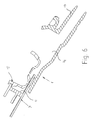
- FIGS. 1 and 2 show an embodiment of a roof assembly for a vehicle, in particular a passenger car.
- the roof assembly comprises a stationary part, here in the form of a frame 1, having attachment means 2 to fix the frame 1 to the bodywork of the vehicle.
- the roof assembly further comprises a closure in the form of one or more closure members, here in the form of a front glass panel 3 and a rear glass panel 4.
- a closure in the form of one or more closure members here in the form of a front glass panel 3 and a rear glass panel 4.
- the panels 3, 4 can be positioned in a closed position in which they separately or jointly close an opening in the fixed roof of the vehicle.
- This fixed roof may be either part of the roof assembly or may be a part of the vehicle in which the roof assembly is mounted.
- the panels 3, 4 can be fixed, but in this embodiment they are both movable from their closed position in the roof opening to an open position in which they at least partly open the roof opening.
- the rear panel can be moved from the closed position downwardly and rearwardly below a roof part that is present behind the roof opening.
- Each panel 3, 4 has an operating mechanism 5, 6 attached under each longitudinal edge of the panel.
- the operating mechanisms 5, 6 are guided in longitudinal guides 7 provided on each longitudinal edge of the frame 1 and extending along a passage opening 8 in the frame 1.
- the operating mechanisms 5, 6 of the panels 3, 4 are controlled by means of a driving mechanism, here including drive cables 9 driven by one or more electric motors 10.
- the frame 1 is provided with a water management system that is provided for draining water collected by the frame 1.
- the management system includes longitudinal drain channels 11, here guide channels formed in the longitudinal guides 7 and also acting to guide parts of the operating mechanisms 5, 6. It also includes a movable water gutter 12, arranged behind the rear panel 4 and being able to follow movements of the rear panel 4 when it is moved rearwardly.
- the water gutter 12 has ends terminating above the drain channels 11 in order to drain water from the water gutter 12 into the longitudinal drain channels 11.
- the frame 1 is provided with water drainage members 13 which are positioned at least on the rear end of the frame 1 substantially behind the longitudinal drain channels 11.
- the water drainage members 13 include a pipe-shaped part to which a water drainage hose (not shown) can be connected. The water may thus flow from the drain channels 11 through the water drainage members 13 into the hoses which end at a position near the bottom of the vehicle in order to allow the water to leave the vehicle.
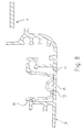
- Figures 3 - 10 show a part of the frame 1 at a location of the water drainage member 13 extending through a wall of the frame 1 and opening to a portion 14 of the frame which is located behind the water drain channel 11 and at a lower level so that the water may flow from the drain channel 11 to the portion 14 of the frame 1 and then into the water drainage member 13.
- the invention proposes the use of a sieve member 15 which on the one hand catches the debris and on the other hand provides sufficient openings to allow water to flow through, also when the debris have been collected.
- the sieve member 15 is attached within the drain channel 11 of the longitudinal guides 7 at the rear end thereof.
- the sieve member 15 has a substantially U-shaped cross section (see Figure 8 ) and is elongated with a plurality of drain openings 16 in the bottom 17 of the sieve member 15.
- the cross section of the sieve member 15 is smaller than that of the drain channel 11, and below the bottom 17 of the sieve member 15 there is created a space 18 to the bottom of the drain channel 11, so that water can flow from the drain openings 16 to the space 18 and then into the portion 14 of the frame 1.
- the elongated cross openings 16 also extend into the side walls 19 of the sieve member 15.
- the side walls 19 of the sieve member 15 are provided with positioning members 20, 21 in order to fix the lateral and vertical position of the sieve member 15 in the drain channel 11.
- Another positioning member 22 may be provided to fix the position of the sieve member 15 in longitudinal direction of the drain channel 11.
- the sieve member 15 has an end wall 23 to prevent the debris from entering the portion 14 behind the sieve member 15.
- the end wall 23 is not completely closed as it should allow a part 24 of the water gutter 12 to pass the end wall 23 when the water gutter 12 is in its rearmost position with the rear panel 4 in its completely open position.
- hardly any debris will reach the end wall 23 as it will be caught by the sieve member 15 in positions spaced from the end wall 23.
- This embodiment of the sieve member can be used for new roof assemblies, so that the sieve members are mounted during the manufacturing process.
- the sieve member 15 can also be used as a service part which is mounted when the roof assembly is already in use. In this case the sieve members 15 should be brought into their position at the rear end of the frame which can hardly be reached because of the overlying fixed roof.
- the invention includes a method to bring the sieve members 15 into their positions of use without having to dismantle of demount the roof assembly.
- This method includes inserting the sieve member 15 from above into the drain channel 11 when a slide 26 of the operating mechanism 6 is in its front or maximally forward position. In this case this is in a venting position of the rear panel 4 in which it is in an inclined position with its rear side moved upwardly.
- the slide 25 of the operating mechanism 5, 6 is then positioned forwardly of the rear side of the roof opening, so that it is possible to position the sieve member 15 by hand into the drain channel 11 at a position just behind the slide 26.
- the operating mechanisms 5, 6 are then moved to their rearward position in the longitudinal guides and during this rearward movement of the slide 25 it pushes the sieve member 15 rearwardly to a position just in front of the position of use or into the position of use in which in this case the positioning member 22 comes into engagement with a counter member in the longitudinal guide 7.
- a retrieval tool which is elongated so that it can be inserted into the drain channel 11 from a position at the roof opening while a hook at the distal end of the tool may be brought into engagement with a retrieval recess 26 on the front end of the sieve member 15 so that the sieve member 15 can be pulled forward by the tool and can be removed from the rain channel 11 for replacement of cleaning purposes.
- the positioning member 22 should then be made such that it can be disengaged from its counter member.
- Figures 12 - 14 show alternative embodiments of the sieve member.
- Figure 12 shows a sieve member 27 which can be mounted in front of the opening of the drainage member 13. It includes a pipe shaped part 28 for insertion into the water drainage member 13 and a hollow sieve 29 having a plurality of drain openings 30 distributed around the sieve 29 so that there will always be an unblocked drain opening even if an amount of debris has accumulated in the frame portion 14.
- Figure 13 shows an embodiment in which a sieve member 31 is formed on the frame at a position above the frame portion 14 and connecting to the rear end of the respective drain channel 11 such that debris from the drain channel 11 will be caught and collected by the sieve member 31.
- Figure 14 shows a sieve member 32 which comprises a scraper provided across the drain channel 11 and being connected to a control member 34 having a control recess 35 that can be engaged by a control tool with which the scraper 33 can be pulled forwardly from its rear position in order to scrape debris from the drain channel 11 to a position where it can be removed from the drain channel 11.
- the scraper can be connected to the water gutter, so that scraping movements are carried out every time the water gutter 12 is moving.
- the scraper can be such that the scraper is only active if it is moved in forward direction.
- the sieve member is positioned upstream of the drainage member within the water drain.
- the invention provides a roof assembly having a sieve member which is effectively preventing blockage of the drain thereby preventing a leakage of drain water into the vehicle.
- sieve members can be used in other positions within the frame depending on the position of drain members that cannot be easily reached by hand to remove debris.
- the water drainage hose may also be replaced by another conduit connected to or formed on the water drainage member.
Landscapes
- Engineering & Computer Science (AREA)
- Mechanical Engineering (AREA)
- Seal Device For Vehicle (AREA)
Abstract
A sieve member (15) for catching debris but allowing water to run through is provided in the drain upstream of said water drainage member.
Description
- The invention relates to a roof assembly for a vehicle having a roof opening in its fixed roof, comprising a stationary part having longitudinal guides positioned on either side of the roof opening, a closure movable at least between a closed position closing the roof opening and an open position in which the closure is at least partly opening the roof opening, a closure operating mechanism for opening and closing said closure, said operating mechanism sliding in said longitudinal guides when opening and closing said closure, and wherein said longitudinal guides each comprise at least a drain channel and a water drainage member for draining water from said drain channel to a water drainage hose, each water drainage member communicating with the respective drain channel on one end, and connecting to the corresponding water drainage hose on its opposite end to form a drain.
- Such roof assembly is known in various embodiments.
- A problem with such roof assemblies is that the water drainage member or hose can become clogged due to debris containing for example dirt and leaves accumulating in the drain channel and flushed to the drainage member.
- It is an object of the present invention to remove or at least reduce this problem.
- For this purpose the invention proposes to use a sieve member for catching debris but allowing water to run through, said sieve member being provided in the drain upstream of said water drainage member.
- Due to this sieve member, the debris cannot reach the drainage member. The shape of the sieve member can be easily chosen such that water can still seep through even if debris have accumulated in front of the sieve, so that a total blockage of the drain will not occur.
- In a first embodiment, the sieve member is mounted to said longitudinal guide, and in particularly mainly in said drain channel. In this way, the dirt and leaves will remain in the drain channel where it is relatively easy to collect and remove the dirt and leaves. This embodiment is also best suited for mounting the sieve after the roof assembly has been built in the vehicle, as the drain channel can easily be reached from inside or outside the vehicle.
- In a particular embodiment the sieve member is fixed in said drain channel and is preferably elongated and has a generally U-shaped cross section fitting within said drain channel with space between the bottom of said sieve member and the drain channel, the bottom of said elongated sieve member having openings and the end of the sieve member adjacent the water drainage member being at least partly closed.
- In this embodiment, the water may seep through the bottom of the sieve member over a relatively great length, thereby further reducing the risk of blocking the sieve member.
- In another embodiment, the sieve member is slidably mounted to said longitudinal guide and is operatively connected to said operating mechanism, said sieve member being constructed as a scraper. In this embodiment, the sieve member will follow movements of the closure operating mechanism, and will scrape any collected dirt and leaves forwardly, which makes removal easier.
- In one development thereof, the roof assembly comprises a transverse water drain channel capable of collecting and draining water into said drain channel, said water drain channel having supports that are slidably connected to said longitudinal guides, said sieve members being connected to said water drain channel supports, for example directly fixed thereto.
- In another embodiment, the water drainage member is provided with a drain pipe for mounting the drainage hose, the sieve member having a mounting part fixed within the drain pipe and a sieve part protruding upstream from the mounting part. This leads to a very simple sieve member.
- The sieve member may be detachable, for example the sieve member may comprise clip fixing members, to fix or detach said sieve to or from said longitudinal guide member, and/or to said water drainage member, and /or to said water drain channel support.
- The invention also includes a method of mounting a sieve member to a vehicle comprising such roof assembly as defined above, comprising the steps of:
- setting the closure operating mechanism in its maximally forward position in the longitudinal guides such that closure is moved away from the rear side of the roof opening and the drain channel can be reached there,
- positioning the sieve member in the drain channel in a position behind the operating mechanism,
- moving the sieve member rearwardly to its position of use.
- By using this method, it is not necessary to demount or dismantle a roof assembly for the vehicle in order to be able to install the sieve assembly in existing roof assemblies.
- This method may include the step of actuating the closure operating mechanism such that it moves to its maximally rearward position thereby taking along the sieve member at least partly to its position of use.
- Further details and advantages of the invention follow from the description with reference to the drawings showing embodiments of the invention by way of example.
-
Figure 1 is a perspective view of en embodiment of the roof assembly according to the invention. -
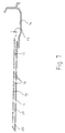
Figure 2 is a plan view of the roof assembly ofFigure 1 . -
Figure 3 shows detail III inFigure 2 on a larger scale. -
Figure 4 is a perspective view of the subject ofFigure 3 . -
Figure 5 is a perspective view of the sieve member used in the embodiment ofFigures 1-4 . -
Figure 6 is a sectional view along the line VI-VI inFigure 3 . -
Figure 7 is a sectional view along the line VII-VII inFigure 3 . -
Figure 8 is a sectional view along the line VIII-VIII inFigure 3 . -
Figure 9 shows detail IX inFigure 4 on a larger scale. -
Figure 10 is a perspective view similar to that ofFigure 4 but showing the closure operating mechanism of the roof assembly in its rearward position. -
Figure 11 is a sectional view according to the line XI-XI inFig. 3 , but showing a water gutter in its rearmost position. -
Figures 12-14 are perspective views of alternative embodiments of a sieve member assembled in their position in the roof assembly. -
Figure 1 and2 show an embodiment of a roof assembly for a vehicle, in particular a passenger car. The roof assembly comprises a stationary part, here in the form of a frame 1, having attachment means 2 to fix the frame 1 to the bodywork of the vehicle. The roof assembly further comprises a closure in the form of one or more closure members, here in the form of afront glass panel 3 and arear glass panel 4. Of course al kinds of other closure arrangements as known in the prior art are conceivable, such slats, folding covers and the like.. Thepanels panels - In order to be able to move the
panels operating mechanisms panel operating mechanism operating mechanisms longitudinal guides 7 provided on each longitudinal edge of the frame 1 and extending along a passage opening 8 in the frame 1. Theoperating mechanisms panels drive cables 9 driven by one or moreelectric motors 10. - The frame 1 is provided with a water management system that is provided for draining water collected by the frame 1. The management system includes
longitudinal drain channels 11, here guide channels formed in thelongitudinal guides 7 and also acting to guide parts of theoperating mechanisms movable water gutter 12, arranged behind therear panel 4 and being able to follow movements of therear panel 4 when it is moved rearwardly. Thewater gutter 12 has ends terminating above thedrain channels 11 in order to drain water from thewater gutter 12 into thelongitudinal drain channels 11. In order to drain the collected water to a position outside the roof assembly and preferably outside the vehicle, the frame 1 is provided withwater drainage members 13 which are positioned at least on the rear end of the frame 1 substantially behind thelongitudinal drain channels 11. Thewater drainage members 13 include a pipe-shaped part to which a water drainage hose (not shown) can be connected. The water may thus flow from thedrain channels 11 through thewater drainage members 13 into the hoses which end at a position near the bottom of the vehicle in order to allow the water to leave the vehicle. -
Figures 3 - 10 show a part of the frame 1 at a location of thewater drainage member 13 extending through a wall of the frame 1 and opening to aportion 14 of the frame which is located behind thewater drain channel 11 and at a lower level so that the water may flow from thedrain channel 11 to theportion 14 of the frame 1 and then into thewater drainage member 13. - In practice it has been shown that debris, for example in the form of dirt and leaves can collect in the
drain channels 11 and then in theportion 14 of the frame 1 in front of the opening of thewater drainage member 13, thereby creating a risk of clogging the opening such that the water cannot leave theportion 14 which may lead to leakage of drain water from the frame 1 into the interior of the vehicle. - In order to minimize the risk of clogging of the
water drainage member 13, the invention proposes the use of asieve member 15 which on the one hand catches the debris and on the other hand provides sufficient openings to allow water to flow through, also when the debris have been collected. - In the embodiment of
Figures 3 - 10 thesieve member 15 is attached within thedrain channel 11 of thelongitudinal guides 7 at the rear end thereof. Thesieve member 15 has a substantially U-shaped cross section (seeFigure 8 ) and is elongated with a plurality ofdrain openings 16 in thebottom 17 of thesieve member 15. - The cross section of the
sieve member 15 is smaller than that of thedrain channel 11, and below thebottom 17 of thesieve member 15 there is created aspace 18 to the bottom of thedrain channel 11, so that water can flow from thedrain openings 16 to thespace 18 and then into theportion 14 of the frame 1. Theelongated cross openings 16 also extend into theside walls 19 of thesieve member 15. Theside walls 19 of thesieve member 15 are provided with positioningmembers sieve member 15 in thedrain channel 11. Another positioning member 22 (seeFigures 4 and9 ) may be provided to fix the position of thesieve member 15 in longitudinal direction of thedrain channel 11. - The
sieve member 15 has anend wall 23 to prevent the debris from entering theportion 14 behind thesieve member 15. Theend wall 23 is not completely closed as it should allow apart 24 of thewater gutter 12 to pass theend wall 23 when thewater gutter 12 is in its rearmost position with therear panel 4 in its completely open position. However, hardly any debris will reach theend wall 23 as it will be caught by thesieve member 15 in positions spaced from theend wall 23. - This embodiment of the sieve member can be used for new roof assemblies, so that the sieve members are mounted during the manufacturing process. However, the
sieve member 15 can also be used as a service part which is mounted when the roof assembly is already in use. In this case thesieve members 15 should be brought into their position at the rear end of the frame which can hardly be reached because of the overlying fixed roof. - The invention includes a method to bring the
sieve members 15 into their positions of use without having to dismantle of demount the roof assembly. This method includes inserting thesieve member 15 from above into thedrain channel 11 when aslide 26 of theoperating mechanism 6 is in its front or maximally forward position. In this case this is in a venting position of therear panel 4 in which it is in an inclined position with its rear side moved upwardly. Theslide 25 of theoperating mechanism sieve member 15 by hand into thedrain channel 11 at a position just behind theslide 26. Theoperating mechanisms slide 25 it pushes thesieve member 15 rearwardly to a position just in front of the position of use or into the position of use in which in this case the positioningmember 22 comes into engagement with a counter member in thelongitudinal guide 7. - For service purposes, for example to clean the
sieve member 15, use may be made of a retrieval tool which is elongated so that it can be inserted into thedrain channel 11 from a position at the roof opening while a hook at the distal end of the tool may be brought into engagement with aretrieval recess 26 on the front end of thesieve member 15 so that thesieve member 15 can be pulled forward by the tool and can be removed from therain channel 11 for replacement of cleaning purposes. The positioningmember 22 should then be made such that it can be disengaged from its counter member. -
Figures 12 - 14 show alternative embodiments of the sieve member.Figure 12 shows asieve member 27 which can be mounted in front of the opening of thedrainage member 13. It includes a pipe shapedpart 28 for insertion into thewater drainage member 13 and ahollow sieve 29 having a plurality ofdrain openings 30 distributed around thesieve 29 so that there will always be an unblocked drain opening even if an amount of debris has accumulated in theframe portion 14. -
Figure 13 shows an embodiment in which asieve member 31 is formed on the frame at a position above theframe portion 14 and connecting to the rear end of therespective drain channel 11 such that debris from thedrain channel 11 will be caught and collected by thesieve member 31. -
Figure 14 shows asieve member 32 which comprises a scraper provided across thedrain channel 11 and being connected to acontrol member 34 having acontrol recess 35 that can be engaged by a control tool with which thescraper 33 can be pulled forwardly from its rear position in order to scrape debris from thedrain channel 11 to a position where it can be removed from thedrain channel 11. As an variation thereof the scraper can be connected to the water gutter, so that scraping movements are carried out every time thewater gutter 12 is moving. The scraper can be such that the scraper is only active if it is moved in forward direction. - In all embodiments described, the sieve member is positioned upstream of the drainage member within the water drain.
- From the forgoing it will be clear that the invention provides a roof assembly having a sieve member which is effectively preventing blockage of the drain thereby preventing a leakage of drain water into the vehicle.
- The invention is not limited to the embodiments shown in the drawings and described above, which may be varied in different manners within the scope of the accompanying claims. For example, sieve members can be used in other positions within the frame depending on the position of drain members that cannot be easily reached by hand to remove debris. The water drainage hose may also be replaced by another conduit connected to or formed on the water drainage member.
Claims (12)
- A roof assembly for a vehicle having a roof opening in its fixed roof, comprising
a stationary part having longitudinal guides positioned on either side of the roof opening, a closure movable at least between a closed position closing the roof opening and an open position in which the closure is at least partly opening the roof opening, a closure operating mechanism for opening and closing said closure, said operating mechanism sliding in said longitudinal guides when opening and closing said closure, and wherein said longitudinal guides each comprise at least a drain channel and a water drainage member for draining water from said longitudinal drain channel to a water drainage hose, each water drainage member communicating with the respective drain channel on one end, and connecting to the corresponding water drainage hose on its opposite end to form a drain, and
a sieve member for catching debris but allowing water to run through, provided in the drain upstream of said water drainage member. - The roof assembly of claim 1, wherein said sieve member is mounted to said longitudinal guide.
- The roof assembly of claim 1, wherein said sieve member is mounted mainly in said drain channel.
- The roof assembly of claim 3, wherein the sieve member is fixed in said drain channel and is preferably elongated and has a generally U-shaped cross section fitting within said drain channel with space between the bottom of said sieve member and the drain channel, the bottom of said elongated sieve member having openings and the end of the sieve member adjacent the water drainage member being at least partly closed.
- The roof assembly of claim 3, wherein said sieve member is slidably mounted to said longitudinal guide and is operatively connected to said operating mechanism, said sieve member being constructed as a scraper.
- The roof assembly of claim 5, comprising a transverse water drain channel capable of collecting and draining water into said drain channel, said water drain channel having supports that are slidably connected to said longitudinal guides, said sieve members being connected to said water drain channel supports.
- The roof assembly of claim 1, wherein said sieve member is directly fixed to said water drainage member.
- The roof assembly of claim 7, wherein the water drainage member is provided with a drain pipe for mounting the drainage hose, the sieve member having a mounting part fixed within the drain pipe and a sieve part protruding upstream from the mounting part.
- The roof assembly of any of the preceding claims, wherein said sieve member is detachable.
- The roof assembly of claim 9, wherein said sieve member comprises clip fixing members, to fix or detach said sieve to or from said longitudinal guide member, and/or to said water drainage member, and /or to said water drain channel support.
- Method of mounting a sieve member to a vehicle comprising the roof assembly of any of claims 3 - 6, comprising the steps of:setting the closure operating mechanism in its maximally forward position in the longitudinal guides such that closure is moved away from the rear side of the roof opening and the drain channel can be reached there,positioning the sieve member in the drain channel in a position behind the operating mechanism,moving the sieve member rearwardly to its position of use.
- The method of claim 11, comprising the step of actuating the closure operating mechanism such that it moves to its maximally rearward position thereby taking along the sieve member at least partly to its position of use.
Priority Applications (3)
| Application Number | Priority Date | Filing Date | Title |
|---|---|---|---|
| EP10151634A EP2353906B1 (en) | 2010-01-26 | 2010-01-26 | Roof assembly and method of mounting a sieve member |
| CN201110022016.9A CN102133853B (en) | 2010-01-26 | 2011-01-20 | Roof assembly and method of mounting a sieve member |
| US13/012,204 US8449025B2 (en) | 2010-01-26 | 2011-01-24 | Roof assembly and method of mounting a sieve member |
Applications Claiming Priority (1)
| Application Number | Priority Date | Filing Date | Title |
|---|---|---|---|
| EP10151634A EP2353906B1 (en) | 2010-01-26 | 2010-01-26 | Roof assembly and method of mounting a sieve member |
Publications (2)
| Publication Number | Publication Date |
|---|---|
| EP2353906A1 true EP2353906A1 (en) | 2011-08-10 |
| EP2353906B1 EP2353906B1 (en) | 2013-03-20 |
Family
ID=42174372
Family Applications (1)
| Application Number | Title | Priority Date | Filing Date |
|---|---|---|---|
| EP10151634A Active EP2353906B1 (en) | 2010-01-26 | 2010-01-26 | Roof assembly and method of mounting a sieve member |
Country Status (3)
| Country | Link |
|---|---|
| US (1) | US8449025B2 (en) |
| EP (1) | EP2353906B1 (en) |
| CN (1) | CN102133853B (en) |
Cited By (1)
| Publication number | Priority date | Publication date | Assignee | Title |
|---|---|---|---|---|
| WO2023144374A1 (en) * | 2022-01-29 | 2023-08-03 | Webasto SE | Drainage system for vehicle roofs and vehicle roof |
Families Citing this family (9)
| Publication number | Priority date | Publication date | Assignee | Title |
|---|---|---|---|---|
| DE102011007004B8 (en) * | 2011-04-07 | 2013-01-10 | Bos Gmbh & Co. Kg | Rollobaueinheit for a motor vehicle |
| CN102529658B (en) * | 2012-01-20 | 2016-03-30 | 重庆长安汽车股份有限公司 | The mounting structure of drainer and skylight glass chute after vehicle dormer window |
| JP2016032982A (en) * | 2014-07-31 | 2016-03-10 | アイシン精機株式会社 | Sunroof drainage device |
| DE102016213823A1 (en) * | 2016-07-27 | 2018-02-01 | Bos Gmbh & Co. Kg | Sunroof system of a motor vehicle and guide rail profile for this purpose |
| KR102429163B1 (en) * | 2016-11-29 | 2022-08-03 | 현대자동차주식회사 | Water Drain Structure of Sunroof in Vehicle |
| US10099539B2 (en) * | 2017-01-20 | 2018-10-16 | Ford Global Technologies, Llc | Variable transmission moon roof module with multiple transparent panels |
| CN107215184A (en) * | 2017-06-21 | 2017-09-29 | 安徽省地坤汽车天窗科技有限公司 | A kind of electronic panoramic roofs Semi-automatic winded curtain system |
| DE102017129328B4 (en) * | 2017-12-08 | 2023-02-02 | Roof Systems Germany Gmbh | Sun blind system for a motor vehicle |
| CN113415132A (en) * | 2021-07-06 | 2021-09-21 | 东风柳州汽车有限公司 | Car canopy drainage structures and car |
Citations (4)
| Publication number | Priority date | Publication date | Assignee | Title |
|---|---|---|---|---|
| DE3803361A1 (en) * | 1987-02-12 | 1988-08-25 | Volkswagen Ag | ARRANGEMENT WITH AN EXTERNAL REAR VIEW MIRROR ON A VEHICLE |
| DE4330582C1 (en) * | 1993-09-09 | 1994-10-27 | Webasto Karosseriesysteme | Frame of a vehicle roof which can be opened |
| DE19540413C1 (en) * | 1995-03-31 | 1996-10-31 | Webasto Karosseriesysteme | Frame with an integral gutter for motor vehicle roof sections |
| DE102005043020B3 (en) * | 2005-09-09 | 2007-02-01 | Webasto Ag | Sliding roof for motor vehicle has water run-off gutter running along longitudinal direction of vehicle |
Family Cites Families (19)
| Publication number | Priority date | Publication date | Assignee | Title |
|---|---|---|---|---|
| US474442A (en) * | 1892-05-10 | Eaves-trough | ||
| US753660A (en) * | 1903-08-10 | 1904-03-01 | George W Boyer | Eaves-trough cleaner. |
| US2457940A (en) * | 1946-08-14 | 1949-01-04 | Joseph W Swenson | Gutter leader unit |
| US2461610A (en) * | 1946-11-01 | 1949-02-15 | Chester R Lord | Screened eaves trough |
| US4726090A (en) * | 1986-01-31 | 1988-02-23 | Kilpatrick Norman K | Gutter cleaning device |
| US4964247A (en) * | 1989-03-20 | 1990-10-23 | The 2500 Corporation | Gutter screening and flushing system |
| JP2918440B2 (en) * | 1993-12-10 | 1999-07-12 | 八千代工業株式会社 | Sunroof device for vehicles |
| USD380655S (en) * | 1996-05-09 | 1997-07-08 | Beverly Dillon | Adjustable, articulated gutter rake |
| US5875590A (en) * | 1997-03-19 | 1999-03-02 | Udelle; Steven D. | Raingutter leaf guard and cleaning device |
| JP4099606B2 (en) * | 1998-03-31 | 2008-06-11 | アイシン精機株式会社 | Sliding roof equipment |
| DE29815104U1 (en) * | 1998-08-22 | 1999-12-30 | Meritor Automotive GmbH, 60314 Frankfurt | Guide mechanism for a vehicle sunroof consisting of at least two slats |
| US6493915B2 (en) * | 1998-11-06 | 2002-12-17 | Vermeulen Hollandia Octroolen Ii B.V. | Method of installing a movable roof assembly in the roof of a vehicle |
| DE19856873C1 (en) * | 1998-12-09 | 2000-02-10 | Cts Fahrzeug Dachsysteme Gmbh | Sliding roof for vehicle has several roof sections with interlinked control cams to tilt and stack the roof sections to the rear of the roof opening |
| DE10232579A1 (en) * | 2002-07-18 | 2004-02-05 | Otto Volz | Method for preventing blockages in rain gutters with sieve or slot inserts to prevent debris from washing into the down pipes |
| US20050093315A1 (en) * | 2003-11-05 | 2005-05-05 | Mitchener Calvin L. | Apparatus and method for cleaning gutters |
| US20060075689A1 (en) * | 2004-10-12 | 2006-04-13 | Karim Hawash | Pivoting gutter guard cleaning system |
| JP4725203B2 (en) * | 2005-06-09 | 2011-07-13 | アイシン精機株式会社 | Sunroof device |
| DE602007009974D1 (en) * | 2007-08-09 | 2010-12-02 | Inalfa Roof Sys Group Bv | roof construction |
| EP2048012B1 (en) * | 2007-10-08 | 2013-04-17 | Inalfa Roof Systems Group B.V. | Open roof construction |
-
2010
- 2010-01-26 EP EP10151634A patent/EP2353906B1/en active Active
-
2011
- 2011-01-20 CN CN201110022016.9A patent/CN102133853B/en active Active
- 2011-01-24 US US13/012,204 patent/US8449025B2/en not_active Expired - Fee Related
Patent Citations (4)
| Publication number | Priority date | Publication date | Assignee | Title |
|---|---|---|---|---|
| DE3803361A1 (en) * | 1987-02-12 | 1988-08-25 | Volkswagen Ag | ARRANGEMENT WITH AN EXTERNAL REAR VIEW MIRROR ON A VEHICLE |
| DE4330582C1 (en) * | 1993-09-09 | 1994-10-27 | Webasto Karosseriesysteme | Frame of a vehicle roof which can be opened |
| DE19540413C1 (en) * | 1995-03-31 | 1996-10-31 | Webasto Karosseriesysteme | Frame with an integral gutter for motor vehicle roof sections |
| DE102005043020B3 (en) * | 2005-09-09 | 2007-02-01 | Webasto Ag | Sliding roof for motor vehicle has water run-off gutter running along longitudinal direction of vehicle |
Cited By (1)
| Publication number | Priority date | Publication date | Assignee | Title |
|---|---|---|---|---|
| WO2023144374A1 (en) * | 2022-01-29 | 2023-08-03 | Webasto SE | Drainage system for vehicle roofs and vehicle roof |
Also Published As
| Publication number | Publication date |
|---|---|
| CN102133853B (en) | 2015-01-07 |
| CN102133853A (en) | 2011-07-27 |
| EP2353906B1 (en) | 2013-03-20 |
| US8449025B2 (en) | 2013-05-28 |
| US20110181077A1 (en) | 2011-07-28 |
Similar Documents
| Publication | Publication Date | Title |
|---|---|---|
| EP2353906B1 (en) | Roof assembly and method of mounting a sieve member | |
| CN214994444U (en) | Green belt device is supplied with in town road catchment | |
| CN113089816B (en) | Urban underground water pipe cleaning and dredging system | |
| KR101813621B1 (en) | Drainage System for Use in Bridges | |
| KR100988919B1 (en) | Foreign body removal device of finger type bridge expansion joint | |
| US5968350A (en) | Device for cleaning trash racks | |
| EP2719892B1 (en) | A blade for a wind turbine, and a servicing unit for a blade | |
| CN210151566U (en) | Highway bridge deck drainage facility | |
| CN114737719A (en) | Waterproof firm roof of assembled house | |
| EP1922219B1 (en) | Vehicle roof | |
| CN222701363U (en) | Building roof drainage device | |
| CN212249701U (en) | Window structure is built in room | |
| CN218473902U (en) | Take self-cleaning's calf transfer device | |
| CN113022277A (en) | Skylight drainage filtering system, vehicle and skylight automatic impurity removal method | |
| US20120297696A1 (en) | Gutter Cover System With Water Dam Channel and Gutter Cleaning System | |
| US20060137258A1 (en) | Gutter cleaning shutter | |
| KR101034289B1 (en) | Overflow sewage treatment device of combined sewage pipe | |
| GB2485424A (en) | Method of adapting a vehicle having a screenwashing apparatus | |
| CN218762898U (en) | Smart street lamp robot with sentry card | |
| CN205767351U (en) | The automatic centralised arrangement of injection machine oil drain pan waste oil | |
| CN215593750U (en) | Water conservancy culvert capable of draining water in time | |
| CN221524023U (en) | Roof cornice waterproof construction | |
| CN112575645A (en) | Road drainage device for sponge city | |
| CN213897285U (en) | Irrigation ditch silt cleaning equipment for irrigation | |
| CN217557133U (en) | Water conservancy water drainage tank |
Legal Events
| Date | Code | Title | Description |
|---|---|---|---|
| PUAI | Public reference made under article 153(3) epc to a published international application that has entered the european phase |
Free format text: ORIGINAL CODE: 0009012 |
|
| AK | Designated contracting states |
Kind code of ref document: A1 Designated state(s): AT BE BG CH CY CZ DE DK EE ES FI FR GB GR HR HU IE IS IT LI LT LU LV MC MK MT NL NO PL PT RO SE SI SK SM TR |
|
| AX | Request for extension of the european patent |
Extension state: AL BA RS |
|
| 17P | Request for examination filed |
Effective date: 20120207 |
|
| GRAP | Despatch of communication of intention to grant a patent |
Free format text: ORIGINAL CODE: EPIDOSNIGR1 |
|
| RIN1 | Information on inventor provided before grant (corrected) |
Inventor name: BOERSMA, EGBERT Inventor name: VERBEEK, LEONARDUS GERARDUS MARIA Inventor name: RELOUW, MICHAEL CORNELIS ANTHONIUS Inventor name: KOK, DANNY WILHELMUS AREND |
|
| GRAS | Grant fee paid |
Free format text: ORIGINAL CODE: EPIDOSNIGR3 |
|
| GRAA | (expected) grant |
Free format text: ORIGINAL CODE: 0009210 |
|
| AK | Designated contracting states |
Kind code of ref document: B1 Designated state(s): AT BE BG CH CY CZ DE DK EE ES FI FR GB GR HR HU IE IS IT LI LT LU LV MC MK MT NL NO PL PT RO SE SI SK SM TR |
|
| REG | Reference to a national code |
Ref country code: GB Ref legal event code: FG4D |
|
| REG | Reference to a national code |
Ref country code: CH Ref legal event code: EP |
|
| REG | Reference to a national code |
Ref country code: IE Ref legal event code: FG4D |
|
| REG | Reference to a national code |
Ref country code: AT Ref legal event code: REF Ref document number: 601848 Country of ref document: AT Kind code of ref document: T Effective date: 20130415 |
|
| REG | Reference to a national code |
Ref country code: DE Ref legal event code: R096 Ref document number: 602010005521 Country of ref document: DE Effective date: 20130516 |
|
| PG25 | Lapsed in a contracting state [announced via postgrant information from national office to epo] |
Ref country code: LT Free format text: LAPSE BECAUSE OF FAILURE TO SUBMIT A TRANSLATION OF THE DESCRIPTION OR TO PAY THE FEE WITHIN THE PRESCRIBED TIME-LIMIT Effective date: 20130320 Ref country code: NO Free format text: LAPSE BECAUSE OF FAILURE TO SUBMIT A TRANSLATION OF THE DESCRIPTION OR TO PAY THE FEE WITHIN THE PRESCRIBED TIME-LIMIT Effective date: 20130620 Ref country code: ES Free format text: LAPSE BECAUSE OF FAILURE TO SUBMIT A TRANSLATION OF THE DESCRIPTION OR TO PAY THE FEE WITHIN THE PRESCRIBED TIME-LIMIT Effective date: 20130701 Ref country code: BG Free format text: LAPSE BECAUSE OF FAILURE TO SUBMIT A TRANSLATION OF THE DESCRIPTION OR TO PAY THE FEE WITHIN THE PRESCRIBED TIME-LIMIT Effective date: 20130620 Ref country code: SE Free format text: LAPSE BECAUSE OF FAILURE TO SUBMIT A TRANSLATION OF THE DESCRIPTION OR TO PAY THE FEE WITHIN THE PRESCRIBED TIME-LIMIT Effective date: 20130320 |
|
| REG | Reference to a national code |
Ref country code: AT Ref legal event code: MK05 Ref document number: 601848 Country of ref document: AT Kind code of ref document: T Effective date: 20130320 |
|
| REG | Reference to a national code |
Ref country code: LT Ref legal event code: MG4D |
|
| PG25 | Lapsed in a contracting state [announced via postgrant information from national office to epo] |
Ref country code: SI Free format text: LAPSE BECAUSE OF FAILURE TO SUBMIT A TRANSLATION OF THE DESCRIPTION OR TO PAY THE FEE WITHIN THE PRESCRIBED TIME-LIMIT Effective date: 20130320 Ref country code: FI Free format text: LAPSE BECAUSE OF FAILURE TO SUBMIT A TRANSLATION OF THE DESCRIPTION OR TO PAY THE FEE WITHIN THE PRESCRIBED TIME-LIMIT Effective date: 20130320 Ref country code: LV Free format text: LAPSE BECAUSE OF FAILURE TO SUBMIT A TRANSLATION OF THE DESCRIPTION OR TO PAY THE FEE WITHIN THE PRESCRIBED TIME-LIMIT Effective date: 20130320 Ref country code: GR Free format text: LAPSE BECAUSE OF FAILURE TO SUBMIT A TRANSLATION OF THE DESCRIPTION OR TO PAY THE FEE WITHIN THE PRESCRIBED TIME-LIMIT Effective date: 20130621 |
|
| REG | Reference to a national code |
Ref country code: NL Ref legal event code: VDEP Effective date: 20130320 |
|
| PG25 | Lapsed in a contracting state [announced via postgrant information from national office to epo] |
Ref country code: BE Free format text: LAPSE BECAUSE OF FAILURE TO SUBMIT A TRANSLATION OF THE DESCRIPTION OR TO PAY THE FEE WITHIN THE PRESCRIBED TIME-LIMIT Effective date: 20130320 Ref country code: HR Free format text: LAPSE BECAUSE OF FAILURE TO SUBMIT A TRANSLATION OF THE DESCRIPTION OR TO PAY THE FEE WITHIN THE PRESCRIBED TIME-LIMIT Effective date: 20130320 |
|
| PG25 | Lapsed in a contracting state [announced via postgrant information from national office to epo] |
Ref country code: IS Free format text: LAPSE BECAUSE OF FAILURE TO SUBMIT A TRANSLATION OF THE DESCRIPTION OR TO PAY THE FEE WITHIN THE PRESCRIBED TIME-LIMIT Effective date: 20130720 Ref country code: RO Free format text: LAPSE BECAUSE OF FAILURE TO SUBMIT A TRANSLATION OF THE DESCRIPTION OR TO PAY THE FEE WITHIN THE PRESCRIBED TIME-LIMIT Effective date: 20130320 Ref country code: CZ Free format text: LAPSE BECAUSE OF FAILURE TO SUBMIT A TRANSLATION OF THE DESCRIPTION OR TO PAY THE FEE WITHIN THE PRESCRIBED TIME-LIMIT Effective date: 20130320 Ref country code: NL Free format text: LAPSE BECAUSE OF FAILURE TO SUBMIT A TRANSLATION OF THE DESCRIPTION OR TO PAY THE FEE WITHIN THE PRESCRIBED TIME-LIMIT Effective date: 20130320 Ref country code: PT Free format text: LAPSE BECAUSE OF FAILURE TO SUBMIT A TRANSLATION OF THE DESCRIPTION OR TO PAY THE FEE WITHIN THE PRESCRIBED TIME-LIMIT Effective date: 20130722 Ref country code: EE Free format text: LAPSE BECAUSE OF FAILURE TO SUBMIT A TRANSLATION OF THE DESCRIPTION OR TO PAY THE FEE WITHIN THE PRESCRIBED TIME-LIMIT Effective date: 20130320 Ref country code: AT Free format text: LAPSE BECAUSE OF FAILURE TO SUBMIT A TRANSLATION OF THE DESCRIPTION OR TO PAY THE FEE WITHIN THE PRESCRIBED TIME-LIMIT Effective date: 20130320 Ref country code: SK Free format text: LAPSE BECAUSE OF FAILURE TO SUBMIT A TRANSLATION OF THE DESCRIPTION OR TO PAY THE FEE WITHIN THE PRESCRIBED TIME-LIMIT Effective date: 20130320 |
|
| PG25 | Lapsed in a contracting state [announced via postgrant information from national office to epo] |
Ref country code: CY Free format text: LAPSE BECAUSE OF FAILURE TO SUBMIT A TRANSLATION OF THE DESCRIPTION OR TO PAY THE FEE WITHIN THE PRESCRIBED TIME-LIMIT Effective date: 20130320 Ref country code: PL Free format text: LAPSE BECAUSE OF FAILURE TO SUBMIT A TRANSLATION OF THE DESCRIPTION OR TO PAY THE FEE WITHIN THE PRESCRIBED TIME-LIMIT Effective date: 20130320 |
|
| PLBE | No opposition filed within time limit |
Free format text: ORIGINAL CODE: 0009261 |
|
| STAA | Information on the status of an ep patent application or granted ep patent |
Free format text: STATUS: NO OPPOSITION FILED WITHIN TIME LIMIT |
|
| PG25 | Lapsed in a contracting state [announced via postgrant information from national office to epo] |
Ref country code: DK Free format text: LAPSE BECAUSE OF FAILURE TO SUBMIT A TRANSLATION OF THE DESCRIPTION OR TO PAY THE FEE WITHIN THE PRESCRIBED TIME-LIMIT Effective date: 20130320 |
|
| 26N | No opposition filed |
Effective date: 20140102 |
|
| PG25 | Lapsed in a contracting state [announced via postgrant information from national office to epo] |
Ref country code: IT Free format text: LAPSE BECAUSE OF FAILURE TO SUBMIT A TRANSLATION OF THE DESCRIPTION OR TO PAY THE FEE WITHIN THE PRESCRIBED TIME-LIMIT Effective date: 20130320 |
|
| REG | Reference to a national code |
Ref country code: DE Ref legal event code: R097 Ref document number: 602010005521 Country of ref document: DE Effective date: 20140102 |
|
| PGFP | Annual fee paid to national office [announced via postgrant information from national office to epo] |
Ref country code: FR Payment date: 20140117 Year of fee payment: 5 |
|
| PG25 | Lapsed in a contracting state [announced via postgrant information from national office to epo] |
Ref country code: LU Free format text: LAPSE BECAUSE OF FAILURE TO SUBMIT A TRANSLATION OF THE DESCRIPTION OR TO PAY THE FEE WITHIN THE PRESCRIBED TIME-LIMIT Effective date: 20140126 |
|
| PGFP | Annual fee paid to national office [announced via postgrant information from national office to epo] |
Ref country code: GB Payment date: 20140127 Year of fee payment: 5 |
|
| REG | Reference to a national code |
Ref country code: CH Ref legal event code: PL |
|
| PG25 | Lapsed in a contracting state [announced via postgrant information from national office to epo] |
Ref country code: CH Free format text: LAPSE BECAUSE OF NON-PAYMENT OF DUE FEES Effective date: 20140131 Ref country code: LI Free format text: LAPSE BECAUSE OF NON-PAYMENT OF DUE FEES Effective date: 20140131 |
|
| REG | Reference to a national code |
Ref country code: IE Ref legal event code: MM4A |
|
| PG25 | Lapsed in a contracting state [announced via postgrant information from national office to epo] |
Ref country code: IE Free format text: LAPSE BECAUSE OF NON-PAYMENT OF DUE FEES Effective date: 20140126 |
|
| PG25 | Lapsed in a contracting state [announced via postgrant information from national office to epo] |
Ref country code: MC Free format text: LAPSE BECAUSE OF FAILURE TO SUBMIT A TRANSLATION OF THE DESCRIPTION OR TO PAY THE FEE WITHIN THE PRESCRIBED TIME-LIMIT Effective date: 20130320 |
|
| GBPC | Gb: european patent ceased through non-payment of renewal fee |
Effective date: 20150126 |
|
| PG25 | Lapsed in a contracting state [announced via postgrant information from national office to epo] |
Ref country code: GB Free format text: LAPSE BECAUSE OF NON-PAYMENT OF DUE FEES Effective date: 20150126 |
|
| REG | Reference to a national code |
Ref country code: FR Ref legal event code: ST Effective date: 20150930 |
|
| PG25 | Lapsed in a contracting state [announced via postgrant information from national office to epo] |
Ref country code: FR Free format text: LAPSE BECAUSE OF NON-PAYMENT OF DUE FEES Effective date: 20150202 |
|
| PG25 | Lapsed in a contracting state [announced via postgrant information from national office to epo] |
Ref country code: MT Free format text: LAPSE BECAUSE OF FAILURE TO SUBMIT A TRANSLATION OF THE DESCRIPTION OR TO PAY THE FEE WITHIN THE PRESCRIBED TIME-LIMIT Effective date: 20130320 |
|
| PG25 | Lapsed in a contracting state [announced via postgrant information from national office to epo] |
Ref country code: SM Free format text: LAPSE BECAUSE OF FAILURE TO SUBMIT A TRANSLATION OF THE DESCRIPTION OR TO PAY THE FEE WITHIN THE PRESCRIBED TIME-LIMIT Effective date: 20130320 |
|
| PG25 | Lapsed in a contracting state [announced via postgrant information from national office to epo] |
Ref country code: TR Free format text: LAPSE BECAUSE OF FAILURE TO SUBMIT A TRANSLATION OF THE DESCRIPTION OR TO PAY THE FEE WITHIN THE PRESCRIBED TIME-LIMIT Effective date: 20130320 Ref country code: HU Free format text: LAPSE BECAUSE OF FAILURE TO SUBMIT A TRANSLATION OF THE DESCRIPTION OR TO PAY THE FEE WITHIN THE PRESCRIBED TIME-LIMIT; INVALID AB INITIO Effective date: 20100126 |
|
| PG25 | Lapsed in a contracting state [announced via postgrant information from national office to epo] |
Ref country code: MK Free format text: LAPSE BECAUSE OF FAILURE TO SUBMIT A TRANSLATION OF THE DESCRIPTION OR TO PAY THE FEE WITHIN THE PRESCRIBED TIME-LIMIT Effective date: 20130320 |
|
| PGFP | Annual fee paid to national office [announced via postgrant information from national office to epo] |
Ref country code: DE Payment date: 20260127 Year of fee payment: 17 |