EP2353801A2 - Working device with robot on movable platform and working method - Google Patents
Working device with robot on movable platform and working method Download PDFInfo
- Publication number
- EP2353801A2 EP2353801A2 EP11000901A EP11000901A EP2353801A2 EP 2353801 A2 EP2353801 A2 EP 2353801A2 EP 11000901 A EP11000901 A EP 11000901A EP 11000901 A EP11000901 A EP 11000901A EP 2353801 A2 EP2353801 A2 EP 2353801A2
- Authority
- EP
- European Patent Office
- Prior art keywords
- working
- workpiece
- robot
- platform
- head
- Prior art date
- Legal status (The legal status is an assumption and is not a legal conclusion. Google has not performed a legal analysis and makes no representation as to the accuracy of the status listed.)
- Withdrawn
Links
Images


Classifications
-
- B—PERFORMING OPERATIONS; TRANSPORTING
- B25—HAND TOOLS; PORTABLE POWER-DRIVEN TOOLS; MANIPULATORS
- B25J—MANIPULATORS; CHAMBERS PROVIDED WITH MANIPULATION DEVICES
- B25J9/00—Programme-controlled manipulators
- B25J9/16—Programme controls
- B25J9/1615—Programme controls characterised by special kind of manipulator, e.g. planar, scara, gantry, cantilever, space, closed chain, passive/active joints and tendon driven manipulators
- B25J9/162—Mobile manipulator, movable base with manipulator arm mounted on it
-
- B—PERFORMING OPERATIONS; TRANSPORTING
- B23—MACHINE TOOLS; METAL-WORKING NOT OTHERWISE PROVIDED FOR
- B23Q—DETAILS, COMPONENTS, OR ACCESSORIES FOR MACHINE TOOLS, e.g. ARRANGEMENTS FOR COPYING OR CONTROLLING; MACHINE TOOLS IN GENERAL CHARACTERISED BY THE CONSTRUCTION OF PARTICULAR DETAILS OR COMPONENTS; COMBINATIONS OR ASSOCIATIONS OF METAL-WORKING MACHINES, NOT DIRECTED TO A PARTICULAR RESULT
- B23Q17/00—Arrangements for observing, indicating or measuring on machine tools
- B23Q17/22—Arrangements for observing, indicating or measuring on machine tools for indicating or measuring existing or desired position of tool or work
- B23Q17/2233—Arrangements for observing, indicating or measuring on machine tools for indicating or measuring existing or desired position of tool or work for adjusting the tool relative to the workpiece
-
- G—PHYSICS
- G05—CONTROLLING; REGULATING
- G05B—CONTROL OR REGULATING SYSTEMS IN GENERAL; FUNCTIONAL ELEMENTS OF SUCH SYSTEMS; MONITORING OR TESTING ARRANGEMENTS FOR SUCH SYSTEMS OR ELEMENTS
- G05B2219/00—Program-control systems
- G05B2219/30—Nc systems
- G05B2219/40—Robotics, robotics mapping to robotics vision
- G05B2219/40298—Manipulator on vehicle, wheels, mobile
Definitions
- the invention relates to a working device with an on a drivable and steerable chassis in several directions on a substrate automatically traversable platform, as set forth in claim 1.
- the path of the industrial robot is determined by a guide along the conveying path of the workpiece, so that only uniform workpieces can be processed.
- the known device is not economical to use.
- the object of the invention is to provide a working device which offers improved flexibility, in particular with regard to processing particularly large workpieces.
- the workpiece detection device is connected to an application control, which is set up for coordinating the platform control and the robot control.
- the platform has three or four wheels, of which at least one is drivable.
- At least one wheel may be positionable or height adjustable in a direction perpendicular to the plane of travel to compensate for unevenness in the ground.
- the robot has at least three, preferably six axes of movement.
- the at least one reference mark may have a reflective surface, for example a reflector or mirror.
- the platform controller and the robot controller are set up so that, during a movement of the platform, the working position is located continuously in a working area of the robot.
- the working head may comprise a machining tool such as a drilling, cutting, milling, grinding and / or polishing tool.
- a handling tool such as gripping, insertion, assembly, joining or rolling tool.
- the workpiece detection device can be arranged in advance in a predetermined working direction in front of the working head.
- the position detection device, the workpiece detection device and / or a workpiece position data acquisition device contactless and in particular work optically. This can be done for example by means of laser measuring technique (laser scanning, laser light-cutting technique, laser line sensor, photogrammetry).
- the invention further relates to a method for carrying out a work operation on a workpiece, comprising a working device according to one of the preceding claims, comprising the steps of: detecting workpiece position data with a workpiece position data acquisition device, determining a working position on the workpiece, transferring the workpiece position data and the data relating to the designated working position to the memory, moving the platform until the working position is within a working range of the robot, moving the working head to the working position, and performing the work on the workpiece.
- Moving the platform and / or moving the working head to the working position and / or performing the work on the workpiece may be performed automatically or automatically either after the workpiece position data and the working position data are completely transferred to the memory have been given or after additionally a start signal has been given to one of the controls.
- the working head follows a processing line along the workpiece.
- Fig. 1 to 4 explain a first embodiment of the invention, in which the working head of the robot is equipped with a drilling tool.
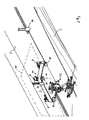
- Fig. 1 shows a plan view of a processing station with a working device according to the invention, wherein a platform 2 on a flat surface 4, for example, a concrete floor of a hall, in a plane of movement is movable.
- the substrate 4 is horizontal and thus also through the surface of the Underground formed movement plane in which the platform is movable.
- Fig. 1 shows a processing situation in which the invention can be used with advantage, namely for processing a particularly large workpiece 6, which in the example shown is a large component such as an aircraft wing, which are not clamped for processing in a conventional machine tool or workpiece holder can.
- Fig. 2 shows that the platform 2 is movable on a chassis, which is formed in this example by four wheels 8, which are mounted in four corners of the entire rectangular platform 2.
- Each wheel 8 is rotatable about a horizontal axis of rotation 10 and pivotable about a vertical pivot axis 12 or steerable.
- At least one of the wheels 8 can be driven in a controlled manner, so that a movement, positioning and orientation of the platform 2 can be realized within the movement plane indicated by 14.
- all four wheels are independently steered and driven independently.
- the vertical distance of the individual wheels 8 from the platform 2 is fixed, it can be provided that to compensate for unevenness of the substrate 4, one or more of the wheels is vertically adjustable relative to the platform 2 and thus the distance of the axis of rotation 10 is adjustable by the platform 2, so that always a defined position of the platform 2 on the ground 4 and within the plane of movement 14 is ensured.
- the working device is provided with a platform control for the coordinated controlled driving of the wheels and with a position control device associated with the platform control in order to be able to position and align the platform within the movement plane in a targeted manner.
- the position detection device comprises at least one, in the illustrated example, a plurality of stationary relative to the ground 2 reference marks 16, which serve as reference points for on the platform 2, about perpendicular to the plane of rotation extending pivot axes arranged position sensors 18.
- the position detection device operates without contact, in particular optically Laser base, each position sensor 18 includes a laser whose beam falls on a reference mark 16 and is reflected back to the position sensor 18 from there.
- Each reference mark 16 has a reflector or mirror which reflects back incident rays in the direction of incidence, or a mirror rotatable about a plane perpendicular to the plane of rotation 14 mirror with a plane perpendicular to the plane of movement mirror surface, which is always adjusted during a positioning process of the platform 2 such that the reflected laser beam falls on the position sensor 18, which is also adjusted.
- a reflector or mirror which reflects back incident rays in the direction of incidence, or a mirror rotatable about a plane perpendicular to the plane of rotation 14 mirror with a plane perpendicular to the plane of movement mirror surface, which is always adjusted during a positioning process of the platform 2 such that the reflected laser beam falls on the position sensor 18, which is also adjusted.
- so many reference marks are provided that a positioning within an entire desired workspace is possible. Therefore, when the workpiece is to be machined from multiple sides, reference marks are required on multiple sides of the workpiece or along the entire circumference of the base 2. In this way, a laser-based distance measurement
- a robot 20 which carries a working head 24 on a robot head 22 and, in the illustrated example, is movable about six movement axes (rotation about three mutually perpendicular axes and translational movement along the axes).
- the working head 24 is provided in the illustrated embodiment with a drilling tool 26 and a drill 28.
- the drilling tool 26 Since for the introduction of boreholes with a tolerance of, for example, +/- 0.1 mm, a particularly accurate positioning of the drill 28 relative to the workpiece 6 is required and certain drilling forces must be transmitted, the drilling tool 26 has three support struts 30 which are pivotable and telescopically extendable on the working head 24 are held and provided at their free ends with adhesive or suction plates 32 to provide a firm grip on the workpiece 6. This ensures that occurring drilling forces do not lead to unwanted displacements of the robot head, which is at a multi-axis robot could not be completely avoided due to the variety of motion options.
- the working head of the robot can be optically calibrated, in addition to the positioning provided by the platform and robot controls ( Fig. 3 ).
- two cameras 34 are placed at a mutual distance on the ground 2, the more fixed in a defined position on the robot head 22, for example, equipped with LED's reference marks 36 (FIG. Fig. 4 ) and can capture their spatial position.
- LED's reference marks 36 FIG. Fig. 4
- Plotted lines of sight between cameras 34 and reference marks 36 illustrate this detection process.
- the positioning of the robot head can be improved relative to the workpiece 6, since the positioning of the platform 2 on the substrate 4 is often subject to certain tolerances, for example due to unevenness of the ground.
- the positioning and positional alignment of the robot head is subject to tolerances due to mechanical play, which can be reduced by direct position measurement of the robot head.
- the robot has a robot control with which it can be moved and positioned in all axes relative to the platform.
- the working head or the robot head has a non-illustrated, the robot controller associated non-contact workpiece detection device, for example, work optically and can be configured as a laser light section device with a laser line sensor.
- a working position has been set in advance on the workpiece, and the workpiece detecting device allows positioning of the working head in or relative to the working position.
- the platform control is in connection with the robot control, so that a coordinated operation of platform and robot is possible.
- the platform controller and / or the robot controller preferably both, is or are provided with or connected to a data memory ; is adapted to take over workpiece position data and the specified working position on the workpiece and can take over and store this data after their capture.
- the workpiece position data are preferably collected optically and in particular by means of photogrammetry, for example for a large workpiece such as an aircraft wing.
- the measurement data is recorded using two cameras and a measuring element (probe) to be held by hand or with the aid of a robot, which is provided with a reference tip and several reference positions equipped with LEDs. While the measuring element with the reference tip is held on a point to be located of the workpiece, the cameras detect the reference positions of the measuring element from two different viewing directions, whereby the data obtained in this way, based on the known camera positions in an absolute position of the reference tip and thus the straight Convert the workpiece point to be located.
- the measured data are adjusted if necessary still adaptation methods to existing CAD data of the workpiece and as a result a numerically determined, is obtained, for example, from individual data interpolated, or mathematically defined, in particular seamless surface of the workpiece, which represents (the whole or parts of) the workpiece position data.
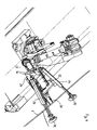
- Fig. 5 and 6 show a working device that is different than the execution after Fig. 1 to 4 is formed with a machining tool for performing a machining operation on a workpiece such as wings.
- the working head 24 has two support rollers 42 which are held on arms 40 and, similar to the support struts 30 in the drilling tool 26, serve for increased precision and for receiving machining forces.
- exemplary shown is a grinding wheel 44, which could alternatively or additionally also be a milling or polishing wheel.
- the working head or the robot head is provided with a workpiece detection device 50, which in this case is designed as an optical detection device in the form of a laser line sensor.
- a workpiece detection device 50 which in this case is designed as an optical detection device in the form of a laser line sensor.
- Explanation shows Fig. 6 two laser beams 52.
- the workpiece detection device 50 is arranged with respect to a working line 54 leading in front of the working head, so that the robot controller contains data for the tracking of the working head along the processing line 54.
- the workpiece detection device can work with eddy current in the case of metallic or CFK workpieces.
- the workpiece geometry (workpiece position data) is first detected by determining defined reference points by means of non-contact, in particular optical, measuring methods and, if appropriate, aligned with an existing CAD data set of the workpiece.
- the position and orientation of the movable platform is also determined metrologically within the processing or handling space and for a driving route continuously. From this information, a web is generated, which, taking into account the achievable working space of the robot, defines a travel route with a defined minimum and / or maximum distance along the workpiece.
- the platform moves continuously or discontinuously to pre-position the working head, for example, with an accuracy of +/- 5 mm, with a more accurate positioning due to unevenness of the ground and other tolerances is usually not possible.
- the platform To perform a work operation on the workpiece, the platform approaches a start position, which is determined from the workpiece position data and the position of the platform. From the same data is a seek motion by the robot with the non-contact workpiece detection device on the robot or working head performed to find a working position accurately and finely positioned, or to find an exact, finely positioned starting point for a processing to be performed along a processing line.
- the starting point on the machining line is set for a work before the start of machining.
- the platform controller and the robot controller can communicate with each other here to support the coarse and fine positioning each other.
- the workpiece detection device detects deviations between the actual machining position of the work head and the desired predetermined machining line.
- the workpiece detection device is arranged leading or leading in front of the working head, so that during the machining process, the calculation of the path correction can be carried out continuously.
Abstract
Description
Die Erfindung betrifft eine Arbeitsvorrichtung mit einer auf einem antreib- und lenkbarem Fahrwerk in mehreren Richtungen auf einem Untergrund selbsttätig verfahrenbaren Plattform, wie sie in Anspruch 1 dargelegt ist.The invention relates to a working device with an on a drivable and steerable chassis in several directions on a substrate automatically traversable platform, as set forth in
Aus der
Hierbei ist nachteilig, dass der Weg des Industrieroboters durch eine Führung entlang des Förderweges des Werkstücks festgelegt ist, so dass an sich nur einheitliche Werkstücke bearbeitet werden können. Insbesondere bei sehr großen Werkstücken ist die bekannte Vorrichtung nicht wirtschaftlich einsetzbar.It is disadvantageous that the path of the industrial robot is determined by a guide along the conveying path of the workpiece, so that only uniform workpieces can be processed. Especially with very large workpieces, the known device is not economical to use.
Die Aufgabe der Erfindung besteht darin, eine Arbeitsvorrichtung zu schaffen, die eine verbesserte Flexibilität insbesondere im Hinblick auf eine Bearbeitung besonders großer Werkstücke bietet.The object of the invention is to provide a working device which offers improved flexibility, in particular with regard to processing particularly large workpieces.
Diese Aufgabe wird erfindungsgemäß durch eine Arbeitsvorrichtung nach Anspruch 1 gelöst.This object is achieved by a working device according to
Es kann vorgesehen sein, dass die Werkstückerfassungseinrichtung mit einer Anwendungssteuerung verbunden ist, die zur Koordinierung der Plattformsteuerung und der Robotersteuerung eingerichtet ist.It can be provided that the workpiece detection device is connected to an application control, which is set up for coordinating the platform control and the robot control.
Bevorzugt ist vorgesehen, dass die Plattform drei oder vier Räder aufweist, von denen mindestens eines antreibbar ist.It is preferably provided that the platform has three or four wheels, of which at least one is drivable.
Mindestens ein Rad kann in einer Richtung senkrecht zu der Bewegungsebene positionierbar oder höheneinstellbar sein, um Unebenheiten des Untergrunds auszugleichen.At least one wheel may be positionable or height adjustable in a direction perpendicular to the plane of travel to compensate for unevenness in the ground.
Zweckmäßigerweise ist vorgesehen, dass der Roboter mindestens drei, vorzugsweise sechs Bewegungsachsen aufweist.Appropriately, it is provided that the robot has at least three, preferably six axes of movement.
Die mindestens eine Referenzmarke kann eine reflektierende Fläche aufweisen, beispielsweise einen Reflektor oder Spiegel.The at least one reference mark may have a reflective surface, for example a reflector or mirror.
In Weiterbildung der Erfindung ist vorgesehen, dass die Plattformsteuerung und die Robotersteuerung so eingerichtet sind, dass bei einer Verfahrbewegung der Plattform die Arbeitsposition kontinuierlich in einem Arbeitsbereich des Roboters liegt.In a further development of the invention, it is provided that the platform controller and the robot controller are set up so that, during a movement of the platform, the working position is located continuously in a working area of the robot.
Der Arbeitskopf kann ein Bearbeitungswerkzeug wie Bohr-, Schneid-, Fräs-, Schleif-und/oder Polierwerkzeug aufweisen. Alternativ oder zusätzlich kann der Arbeitskopf ein Handhabungswerkzeug wie Greif-, Einsetz-, Montage-, Füge- oder Abrollwerkzeug aufweisen.The working head may comprise a machining tool such as a drilling, cutting, milling, grinding and / or polishing tool. Alternatively or additionally, the working head may comprise a handling tool such as gripping, insertion, assembly, joining or rolling tool.
Die Werkstückerfassungseinrichtung kann in einer vorgegebenen Arbeitsrichtung vor dem Arbeitskopf vorlaufend angeordnet sein.The workpiece detection device can be arranged in advance in a predetermined working direction in front of the working head.
Zweckmäßigerweise ist vorgesehen, dass die Positionserfassungseinrichtung, die Werkstückerfassungseinrichtung und/oder eine Werkstück-Positionsdatenerfassungseinrichtung berührungslos und insbesondere optisch arbeiten. Dies kann beispielsweise mittels Lasermeßtechnik (Laserabtastung, Laserlichtschnitttechnik, Laserliniensensor, Photogrammetrie) erfolgen.Appropriately, it is provided that the position detection device, the workpiece detection device and / or a workpiece position data acquisition device contactless and in particular work optically. This can be done for example by means of laser measuring technique (laser scanning, laser light-cutting technique, laser line sensor, photogrammetry).
Die Erfindung betrifft weiterhin ein Verfahren zum Ausführen eines Arbeitsvorgangs an einem Werkstück, mit einer Arbeitsvorrichtung nach einem der vorangehenden Ansprüche, mit den Schritten: Erfassen von Werkstück-Positionsdaten mit einer Werkstück-Positionsdatenerfassungseinrichtung, Festlegen einer Arbeitsposition an dem Werkstück, Übergeben der Werkstück-Positionsdaten und der Daten betreffend die festgesetzte Arbeitsposition an den Speicher, Bewegen der Plattform, bis die Arbeitsposition in einem Arbeitsbereich des Roboters liegt, Bewegen des Arbeitskopfs an die Arbeitsposition, und Ausführen des Arbeitsvorgangs an dem Werkstück.The invention further relates to a method for carrying out a work operation on a workpiece, comprising a working device according to one of the preceding claims, comprising the steps of: detecting workpiece position data with a workpiece position data acquisition device, determining a working position on the workpiece, transferring the workpiece position data and the data relating to the designated working position to the memory, moving the platform until the working position is within a working range of the robot, moving the working head to the working position, and performing the work on the workpiece.
Das Bewegen der Plattform und/oder das Bewegen des Arbeitskopfs an die Arbeitsposition und/oder das Ausführen des Arbeitsvorgangs an dem Werkstück kann bzw. können selbsttätig oder automatisch ausgeführt werden, entweder nachdem die Werkstück-Positionsdaten und die Arbeitspositions-Daten vollständig an den Speicher übergeben worden sind, oder nachdem zusätzlich noch ein Startsignal an eine der Steuerungen gegeben worden ist.Moving the platform and / or moving the working head to the working position and / or performing the work on the workpiece may be performed automatically or automatically either after the workpiece position data and the working position data are completely transferred to the memory have been given or after additionally a start signal has been given to one of the controls.
Zweckmäßigerweise ist vorgesehen, dass der Arbeitskopf einer Bearbeitungslinie entlang des Werkstücks folgt.Appropriately, it is provided that the working head follows a processing line along the workpiece.
Die Erfindung wird nachfolgend anhand eines Ausführungsbeispiels erläutert, wobei auf eine Zeichnung Bezug genommen ist, in der
-
Fig. 1 eine schematische Draufsicht auf eine auf einem Untergrund verfahrbare Arbeitsvorrichtung zeigt, -
Fig. 2 eine perspektivische Ansicht der Arbeitsvorrichtung im Einsatz an einem Werkstück zeigt, -
Fig. 3 eine perspektivische Ansicht von oben entsprechendFig. 2 zeigt, -
Fig. 4 eine vergrößerte perspektivische Ansicht des Roboters und des Arbeitskopfs nachFig. 5 zeigt, -
Fig. 5 eine perspektivische seitliche Ansicht einer Arbeitsvorrichtung mit einem anderen Arbeitskopf zeigt, und -
Fig. 6 eine vergrößerte perspektivische Ansicht des Roboters und des Arbeitskopfs nachFig. 5 . zeigt.
-
Fig. 1 FIG. 2 shows a schematic plan view of a working device movable on a ground, FIG. -
Fig. 2 shows a perspective view of the working device in use on a workpiece, -
Fig. 3 a perspective view from above accordinglyFig. 2 shows, -
Fig. 4 an enlarged perspective view of the robot and the working head afterFig. 5 shows, -
Fig. 5 shows a perspective side view of a working device with another working head, and -
Fig. 6 an enlarged perspective view of the robot and the working head afterFig. 5 , shows.
Obwohl in dem dargestellten Beispiel der vertikale Abstand der einzelnen Räder 8 von der Plattform 2 unveränderlich ist, kann vorgesehen sein, dass zum Ausgleich von Unebenheiten des Untergrunds 4 eines oder mehrere der Räder relativ zu der Plattform 2 vertikal verstellbar ist und somit der Abstand der Drehachse 10 von der Plattform 2 einstellbar ist, so dass stets eine definierte Position der Plattform 2 auf dem Untergrund 4 und innerhalb der Bewegungsebene 14 gewährleistet ist.Although in the illustrated example, the vertical distance of the
Die Arbeitsvorrichtung ist mit einer Plattformsteuerung zum koordiniert gesteuerten Antrieb der Räder und mit einer der Plattformsteuerung zugeordneten Positionserfassungseinrichtung versehen, um die Plattform innerhalb der Bewegungsebene gezielt positionieren und ausrichten zu können. Die Positionserfassungseinrichtung umfasst mindestens eine, in dem dargestellten Beispiel mehrere bezüglich des Untergrunds 2 ortsfeste Referenzmarken 16, die als Bezugspunkte für auf der Plattform 2, um senkrecht zur Bewegungsebene verlaufende Schwenkachsen drehbare angeordnete Positionssensoren 18 dienen. In dem dargestellten Beispiel arbeitet die Positionserfassungseinrichtung berührungslos, insbesondere optisch auf Laserbasis, wobei jeder Positionssensor 18 einen Laser enthält, dessen Strahl auf eine Referenzmarke 16 fällt und von dort zu dem Positionssensor 18 zurückreflektiert wird. Jede Referenzmarke 16 weist einen Reflektor oder Spiegel auf, der einfallende Strahlen in Einfallrichtung zurückwirft, oder auch einen um eine zur Bewegungsebene 14 senkrechte Drehachse drehbaren Spiegel mit einer zur Bewegungsebene senkrechten Spiegelfläche, der während eines Positionierungsvorganges der Plattform 2 stets derart nachgestellt wird, dass der reflektierte Laserstrahl auf den Positionssensor 18 fällt, der ebenfalls nachgestellt wird. Zweckmäßig sind so viele Referenzmarken vorgesehen, dass eine Positionierung innerhalb eines gesamten gewünschten Arbeitsbereichs möglich ist. Wenn das Werkstück von mehreren Seiten bearbeitet werden soll, sind daher Referenzmarken an mehreren Seiten des Werkstücks oder entlang des gesamten Umfangs des Untergrunds 2 erforderlich. Auf diese Weise kann eine lasergestützte Abstandsmessung vorgenommen werden, die eine Positionsbestimmung hinsichtlich Position und Ausrichtung der Plattform in der Bewegungsebene ermöglicht. Die Referenzmarken ermöglichen auch die Definition eines Koordinatensystems eines Arbeitsraums.The working device is provided with a platform control for the coordinated controlled driving of the wheels and with a position control device associated with the platform control in order to be able to position and align the platform within the movement plane in a targeted manner. The position detection device comprises at least one, in the illustrated example, a plurality of stationary relative to the
Auf der Plattform 2 ist ein Roboter 20 angebracht, der an einem Roboterkopf 22 einen Arbeitskopf 24 trägt und in dem dargestellten Beispiel um sechs Bewegungsachsen (Drehbarkeit um drei zueinander senkrechte Achsen sowie translatorische Bewegung entlang der Achsen) bewegbar ist. Der Arbeitskopf 24 ist in dem dargestellten Ausführungsbeispiel mit einem Bohrwerkzeug 26 und einem Bohrer 28 versehen.Mounted on the
Da für die Einbringung von Bohrlöchern mit einer Toleranz mit beispielsweise +/- 0,1 mm eine besonders genaue Positionierung des Bohrers 28 relativ zum Werkstück 6 erforderlich ist und auch gewisse Bohrkräfte übertragen werden müssen, weist das Bohrwerkzeug 26 drei Stützstreben 30 auf, die schwenkbar und teleskopartig ausfahrbar an dem Arbeitskopf 24 gehalten sind und an ihren freien Enden mit Haft- oder Saugtellern 32 versehen sind, um einen festen Halt am Werkstück 6 zu vermitteln. Damit ist gewährleistet, dass auftretende Bohrkräfte nicht zu unerwünschten Verlagerungen des Roboterkopfs führen, die sich bei einem Mehrachsroboter auf Grund der vielfältigen Bewegungsmöglichkeiten nicht vollständig vermeiden ließen.Since for the introduction of boreholes with a tolerance of, for example, +/- 0.1 mm, a particularly accurate positioning of the
Zur Erhöhung der Präzision bei bestimmten Arbeiten, wie beispielsweise beim Einbringen von Bohrungen, kann der Arbeitskopf des Roboters, zusätzlich zu der ohnehin gegebenen Positionierung durch die Plattform- und Robotersteuerung, optisch eingemessen werden (
Der Roboter weist eine Robotersteuerung auf, mit der er in sämtlichen Achsen relativ zu der Plattform beweg- und positionierbar ist. Der Arbeitskopf oder der Roboterkopf weist eine nicht dargestellte, der Robotersteuerung zugeordnete berührungslose Werkstückerfassungseinrichtung auf, die beispielsweise optisch arbeiten und als Laserlichtschnitteinrichtung mit einem Laser-Liniensensor ausgebildet sein kann. An dem Werkstück ist vorab eine Arbeitsposition festgelegt worden, und die Werkstückerfassungseinrichtung ermöglicht eine Positionierung des Arbeitskopfs in der oder relativ zu der Arbeitsposition.The robot has a robot control with which it can be moved and positioned in all axes relative to the platform. The working head or the robot head has a non-illustrated, the robot controller associated non-contact workpiece detection device, for example, work optically and can be configured as a laser light section device with a laser line sensor. A working position has been set in advance on the workpiece, and the workpiece detecting device allows positioning of the working head in or relative to the working position.
Die Plattformsteuerung steht in Verbindung mit der Robotersteuerung, so dass ein aufeinander abgestimmter Betrieb von Plattform und Roboter möglich ist.The platform control is in connection with the robot control, so that a coordinated operation of platform and robot is possible.
Die Plattformsteuerung und/oder die Robotersteuerung, vorzugsweise beide, ist bzw. sind mit einem Datenspeicher versehen oder verbunden; der zum Übernehmen von Werkstück-Positionsdaten und der festgelegten Arbeitsposition an dem Werkstück eingerichtet ist und diese Daten nach deren Erfassung übernehmen und speichern kann.The platform controller and / or the robot controller, preferably both, is or are provided with or connected to a data memory ; is adapted to take over workpiece position data and the specified working position on the workpiece and can take over and store this data after their capture.
Die Werkstück-Positionsdaten werden beispielsweise für ein großes Werkstück wie einen Flugzeugflügel bevorzugt optisch und insbesondere mittels Photogrammetrie erhoben. Die Messdatenaufnahme erfolgt mit zwei Kameras und einem von Hand oder mit Hilfe eines Roboters zu haltenden Messelement (Meßtaster), welches mit einer Referenzspitze und mehreren mit LED's bestückten Referenzpositionen versehen ist. Während das Messelement mit der Referenzspitze auf einen zu lokalisierenden Punkt des Werkstücks gehalten wird, erfassen die Kameras aus zwei unterschiedlichen Blickrichtungen die Referenzpositionen des Messelements, wobei sich die auf diese Weise erhaltenen Daten anhand der bekannten Kamerapositionen in eine absolute Position der Referenzspitze und damit des gerade zu lokalisierenden Werkstückpunkts umrechnen lassen.The workpiece position data are preferably collected optically and in particular by means of photogrammetry, for example for a large workpiece such as an aircraft wing. The measurement data is recorded using two cameras and a measuring element (probe) to be held by hand or with the aid of a robot, which is provided with a reference tip and several reference positions equipped with LEDs. While the measuring element with the reference tip is held on a point to be located of the workpiece, the cameras detect the reference positions of the measuring element from two different viewing directions, whereby the data obtained in this way, based on the known camera positions in an absolute position of the reference tip and thus the straight Convert the workpiece point to be located.
An dem Werkstück, beispielsweise einem Flügel, werden so zahlreiche Punkte auf dessen Oberfläche als Referenzpunkte erhoben und anschließend zu einem Modell zusammengefasst, wobei die gemessenen Daten ggf. noch über Anpassungsverfahren an vorhandene CAD-Daten des Werkstücks angeglichen werden und als Ergebnis eine numerisch bestimmte, etwa aus Einzeldaten interpolierte, oder mathematisch definierte, insbesondere lückenlose Oberfläche des Werkstücks erhalten wird, die (ganz oder Teile davon) die Werkstück-Positionsdaten darstellt.On the workpiece, such as a wing, so many points are collected on its surface as reference points and then combined into a model, the measured data are adjusted if necessary still adaptation methods to existing CAD data of the workpiece and as a result a numerically determined, is obtained, for example, from individual data interpolated, or mathematically defined, in particular seamless surface of the workpiece, which represents (the whole or parts of) the workpiece position data.
Zur Verfolgung einer vorgegebenen Bearbeitungslinie ist der Arbeitskopf oder der Roboterkopf mit einer Werkstückerfassungseinrichtung 50 versehen, die in diesem Fall als optische Erfassungseinrichtung in Form eines Laser-Liniensensors ausgebildet ist. Erläuterungshalber zeigt
Zur Bearbeitung eines Werkstücks wird zunächst die Werkstückgeometrie (Werkstück-Positionsdaten) durch Ermittlung definierter Referenzpunkte mittels berührungsloser, insbesondere optischer Messverfahren erfasst und gegebenenfalls mit einem vorhanden CAD-Datensatz des Werkstücks abgeglichen. Die Position und Orientierung der verfahrbaren Plattform wird ebenfalls messtechnisch innerhalb des Bearbeitungs- oder Handhabungsraums und für eine Fahrroute fortlaufend bestimmt. Aus diesen Informationen wird eine Bahn erzeugt, die unter Berücksichtigung des erreichbaren Arbeitsraums des Roboters eine Fahrroute mit einem festgelegten Mindest- und/oder Höchstabstand entlang des Werkstücks definiert. Die Plattform fährt dabei kontinuierlich oder diskontinuierlich, um den Arbeitskopf vorzupositionieren, beispielsweise mit einer Genauigkeit von +/- 5 mm, wobei in der Regel eine genauere Positionierung auf Grund von Unebenheiten des Untergrunds und sonstiger Toleranzen nicht möglich ist.For processing a workpiece, the workpiece geometry (workpiece position data) is first detected by determining defined reference points by means of non-contact, in particular optical, measuring methods and, if appropriate, aligned with an existing CAD data set of the workpiece. The position and orientation of the movable platform is also determined metrologically within the processing or handling space and for a driving route continuously. From this information, a web is generated, which, taking into account the achievable working space of the robot, defines a travel route with a defined minimum and / or maximum distance along the workpiece. The platform moves continuously or discontinuously to pre-position the working head, for example, with an accuracy of +/- 5 mm, with a more accurate positioning due to unevenness of the ground and other tolerances is usually not possible.
Zur Ausführung eines Arbeitsvorgangs an dem Werkstück fährt die Plattform eine Startposition an, die aus den Werkstück-Positionsdaten und der Position der Plattform ermittelt wird. Aus den gleichen Daten wird eine Suchbewegung durch den Roboter mit der berührungslosen Werkstückerfassungseinrichtung am Roboter- oder Arbeitskopf durchgeführt, um eine Arbeitsposition exakt und fein positioniert zu finden, oder einen exakten, fein positionierten Startpunkt für eine entlang einer Bearbeitungslinie durchzuführende Bearbeitung zu finden. Der Anfangspunkt auf der Bearbeitungslinie wird für einen Arbeitsvorgang vor Bearbeitungsbeginn festgelegt.To perform a work operation on the workpiece, the platform approaches a start position, which is determined from the workpiece position data and the position of the platform. From the same data is a seek motion by the robot with the non-contact workpiece detection device on the robot or working head performed to find a working position accurately and finely positioned, or to find an exact, finely positioned starting point for a processing to be performed along a processing line. The starting point on the machining line is set for a work before the start of machining.
Die Plattformsteuerung und die Robotersteuerung können hierbei miteinander kommunizieren, um die Grob- und Feinpositionierung gegenseitig zu unterstützen.The platform controller and the robot controller can communicate with each other here to support the coarse and fine positioning each other.
Wenn eine Bearbeitung entlang einer Bearbeitungslinie ausgeführt wird, erfolgt durch die Werkstückerfassungseinrichtung eine Erfassung von Abweichungen zwischen der tatsächlichen Bearbeitungsposition des Arbeitskopfs und der gewünschten vorgegebenen Bearbeitungslinie. Zu diesem Zweck ist die Werkstückerfassungseinrichtung vorlaufend oder voreilend vor dem Arbeitskopf angeordnet, damit während des Bearbeitungsvorgangs die Berechnung der Bahnkorrektur kontinuierlich erfolgen kann.When machining is performed along a machining line, the workpiece detection device detects deviations between the actual machining position of the work head and the desired predetermined machining line. For this purpose, the workpiece detection device is arranged leading or leading in front of the working head, so that during the machining process, the calculation of the path correction can be carried out continuously.
- 22
- Plattformplatform
- 44
- Untergrundunderground
- 66
- Werkstückworkpiece
- 88th
- Radwheel
- 1010
- Drehachseaxis of rotation
- 1212
- Schwenkachseswivel axis
- 1414
- Bewegungsebenemovement plane
- 1616
- Referenzmarkereference mark
- 1818
- Positionssensorposition sensor
- 2020
- Roboterrobot
- 2222
- Roboterkopfrobot head
- 2424
- Arbeitskopfworking head
- 2626
- Bohrwerkzeugdrilling
- 2828
- Bohrerdrill
- 3030
- Stützstrebesupport strut
- 3232
- Haft- / SaugtellerAdhesive / suction plate
- 3434
- Kameracamera
- 3636
- Referenzmarkereference mark
- 4040
- Auslegerboom
- 4242
- Abstützrollesupport roller
- 4444
- Schleifscheibegrinding wheel
- 5050
- WerkstückerfassungseinrichtungWorkpiece detector
- 5252
- Laserstrahllaser beam
- 5454
- Bearbeitungslinieprocessing line
Claims (13)
Applications Claiming Priority (1)
| Application Number | Priority Date | Filing Date | Title |
|---|---|---|---|
| DE102010007591A DE102010007591A1 (en) | 2010-02-04 | 2010-02-04 | Working device with robot on movable platform as well as working method |
Publications (2)
| Publication Number | Publication Date |
|---|---|
| EP2353801A2 true EP2353801A2 (en) | 2011-08-10 |
| EP2353801A3 EP2353801A3 (en) | 2015-09-16 |
Family
ID=44065433
Family Applications (1)
| Application Number | Title | Priority Date | Filing Date |
|---|---|---|---|
| EP11000901.6A Withdrawn EP2353801A3 (en) | 2010-02-04 | 2011-02-04 | Working device with robot on movable platform and working method |
Country Status (2)
| Country | Link |
|---|---|
| EP (1) | EP2353801A3 (en) |
| DE (1) | DE102010007591A1 (en) |
Cited By (9)
| Publication number | Priority date | Publication date | Assignee | Title |
|---|---|---|---|---|
| CN102896631A (en) * | 2012-10-09 | 2013-01-30 | 温州大学 | Real-time/on-line azimuth adjustment device and method |
| US10635758B2 (en) | 2016-07-15 | 2020-04-28 | Fastbrick Ip Pty Ltd | Brick/block laying machine incorporated in a vehicle |
| US10865578B2 (en) | 2016-07-15 | 2020-12-15 | Fastbrick Ip Pty Ltd | Boom for material transport |
| CN113941755A (en) * | 2020-07-15 | 2022-01-18 | 华东交通大学 | Freight train disassembles side wall and preapres for an unfavorable turn of events shape fixing device |
| CN114193480A (en) * | 2022-01-04 | 2022-03-18 | 中国十七冶集团有限公司 | Crawler-type spraying robot based on building steel structure high-altitude operation and spraying method |
| US11401115B2 (en) | 2017-10-11 | 2022-08-02 | Fastbrick Ip Pty Ltd | Machine for conveying objects and multi-bay carousel for use therewith |
| US11441899B2 (en) | 2017-07-05 | 2022-09-13 | Fastbrick Ip Pty Ltd | Real time position and orientation tracker |
| US11794303B2 (en) | 2019-01-08 | 2023-10-24 | General Electric Company | Systems and methods for polishing component surfaces using polishing tool mounted on motorized apparatus |
| CN113941755B (en) * | 2020-07-15 | 2024-04-12 | 华东交通大学 | Anti-deformation fixing device for dismantling side wall of freight train |
Families Citing this family (6)
| Publication number | Priority date | Publication date | Assignee | Title |
|---|---|---|---|---|
| DE102014217352B4 (en) * | 2014-08-29 | 2018-04-19 | HAP Handhabungs-, Automatisierungs- und Präzisionstechnik GmbH | Mobile device for manipulating objects |
| DE102015210255A1 (en) * | 2015-06-03 | 2016-12-08 | Fraunhofer-Gesellschaft zur Förderung der angewandten Forschung e.V. | Method and arrangement for surface machining a stationary mounted workpiece with a mounted on a articulated robot tool |
| DE102016201687A1 (en) * | 2016-02-04 | 2017-08-10 | Robomotion Gmbh | System and method for positioning a robot cell relative to a workstation |
| DE102016103526A1 (en) * | 2016-02-29 | 2017-08-31 | Christian Schmid | Self-propelled processing device |
| DE102016204465A1 (en) * | 2016-03-17 | 2017-09-21 | Kuka Systems Gmbh | Force support in sensitive robot processes |
| DE102019113466A1 (en) * | 2019-05-21 | 2020-11-26 | Homag Automation Gmbh | Industrial robots for handling and / or processing workpieces with a mobile platform, cell for handling and / or processing workpieces and methods for handling workpieces |
Citations (1)
| Publication number | Priority date | Publication date | Assignee | Title |
|---|---|---|---|---|
| DE102007045143A1 (en) | 2007-09-20 | 2009-04-02 | Mrk-Systeme Gmbh | Workpiece i.e. vehicle body, processing and/or manufacturing plant for use in automobile production, has arm of robot positioning component for assembling/installation purposes or arm of robot carrying tool for processing of workpiece |
Family Cites Families (4)
| Publication number | Priority date | Publication date | Assignee | Title |
|---|---|---|---|---|
| US7072739B2 (en) * | 2003-05-29 | 2006-07-04 | Hewlett-Packard Development Company, L.P. | Data center robotic device |
| US7398843B2 (en) * | 2005-08-30 | 2008-07-15 | Boston Dynamics, Inc. | Reconfigurable robot drive |
| EP1815938B1 (en) * | 2006-02-06 | 2009-10-21 | Force Technology | Carriage for automating welding, brazing, cutting and surface treatment processes |
| DE102007016662C5 (en) * | 2007-04-04 | 2022-09-15 | Kuka Deutschland Gmbh | Omnidirectional vehicle and mobile industrial robot |
-
2010
- 2010-02-04 DE DE102010007591A patent/DE102010007591A1/en not_active Ceased
-
2011
- 2011-02-04 EP EP11000901.6A patent/EP2353801A3/en not_active Withdrawn
Patent Citations (1)
| Publication number | Priority date | Publication date | Assignee | Title |
|---|---|---|---|---|
| DE102007045143A1 (en) | 2007-09-20 | 2009-04-02 | Mrk-Systeme Gmbh | Workpiece i.e. vehicle body, processing and/or manufacturing plant for use in automobile production, has arm of robot positioning component for assembling/installation purposes or arm of robot carrying tool for processing of workpiece |
Cited By (16)
| Publication number | Priority date | Publication date | Assignee | Title |
|---|---|---|---|---|
| CN102896631A (en) * | 2012-10-09 | 2013-01-30 | 温州大学 | Real-time/on-line azimuth adjustment device and method |
| US11842124B2 (en) | 2016-07-15 | 2023-12-12 | Fastbrick Ip Pty Ltd | Dynamic compensation of a robot arm mounted on a flexible arm |
| US10876308B2 (en) | 2016-07-15 | 2020-12-29 | Fastbrick Ip Pty Ltd | Boom for material transport |
| US11106836B2 (en) | 2016-07-15 | 2021-08-31 | Fastbrick Ip Pty Ltd | Brick/block laying machine incorporated in a vehicle |
| US10635758B2 (en) | 2016-07-15 | 2020-04-28 | Fastbrick Ip Pty Ltd | Brick/block laying machine incorporated in a vehicle |
| US10865578B2 (en) | 2016-07-15 | 2020-12-15 | Fastbrick Ip Pty Ltd | Boom for material transport |
| US11299894B2 (en) | 2016-07-15 | 2022-04-12 | Fastbrick Ip Pty Ltd | Boom for material transport |
| US11687686B2 (en) | 2016-07-15 | 2023-06-27 | Fastbrick Ip Pty Ltd | Brick/block laying machine incorporated in a vehicle |
| US11441899B2 (en) | 2017-07-05 | 2022-09-13 | Fastbrick Ip Pty Ltd | Real time position and orientation tracker |
| US11958193B2 (en) | 2017-08-17 | 2024-04-16 | Fastbrick Ip Pty Ltd | Communication system for an interaction system |
| US11401115B2 (en) | 2017-10-11 | 2022-08-02 | Fastbrick Ip Pty Ltd | Machine for conveying objects and multi-bay carousel for use therewith |
| US11794303B2 (en) | 2019-01-08 | 2023-10-24 | General Electric Company | Systems and methods for polishing component surfaces using polishing tool mounted on motorized apparatus |
| CN113941755B (en) * | 2020-07-15 | 2024-04-12 | 华东交通大学 | Anti-deformation fixing device for dismantling side wall of freight train |
| CN113941755A (en) * | 2020-07-15 | 2022-01-18 | 华东交通大学 | Freight train disassembles side wall and preapres for an unfavorable turn of events shape fixing device |
| CN114193480A (en) * | 2022-01-04 | 2022-03-18 | 中国十七冶集团有限公司 | Crawler-type spraying robot based on building steel structure high-altitude operation and spraying method |
| CN114193480B (en) * | 2022-01-04 | 2024-04-12 | 中国十七冶集团有限公司 | Crawler-type spraying robot and spraying method based on building steel structure high-altitude operation |
Also Published As
| Publication number | Publication date |
|---|---|
| DE102010007591A1 (en) | 2011-08-04 |
| EP2353801A3 (en) | 2015-09-16 |
Similar Documents
| Publication | Publication Date | Title |
|---|---|---|
| EP2353801A2 (en) | Working device with robot on movable platform and working method | |
| EP1189732B1 (en) | Method and device for calibrating robot measuring stations, manipulators and associated optical measuring devices | |
| EP2390737B1 (en) | Method for machine measurement | |
| EP3302857A1 (en) | Method and arrangement for introducing boreholes into a surface of a workpiece mounted in a stationary manner using a boring tool attached to an articulated-arm robot | |
| DE19615069A1 (en) | Procedure for panning machine tool esp. laser beam cutter using edge tracking on workpiece | |
| DE102012003690A1 (en) | Mobile robot | |
| EP1503874A2 (en) | Production device, especially a bending press, and method for operating said production device | |
| WO2014139938A1 (en) | Method and apparatus for online calibration and for guiding a multiaxis jointed-arm robot | |
| EP3129193B1 (en) | Manipulation device and manipulation method | |
| CN108202259B (en) | Machine tool with assembled configuration with cantilevered tool | |
| WO2019048280A1 (en) | Autonomous omnidirectional vehicle with a drilling device | |
| DE202006005916U1 (en) | Monitoring device for jet mechanisms e.g. remote lasers, has jet e.g. laser beam for treatment of workpiece and movable jet head e.g. laser head, where monitoring device has sensor unit attached to jet head, preferably at exit of jet optics | |
| EP3218149A1 (en) | Retaining device, machining device and method | |
| DE202010008808U1 (en) | processing tool | |
| DE10133624A1 (en) | Arrangement for determining corrected movement data for a specified sequence of movement of a movable device, such as an industrial robot, uses computer unit for ascertaining corrected movement data via a reference device | |
| EP3064417B1 (en) | Transport device for moving work pieces for car bodywork construction in the motor vehicle industry | |
| DE102007055453B4 (en) | Apparatus and method for laser welding | |
| DE102011052602A1 (en) | Method for processing large-sized device, involves arranging two markers on machine tool that is positioned or mounted in region of site processed at large-sized device, and positions of markers are detected | |
| EP1387996B1 (en) | Method for measuring and/or machining a workpiece | |
| DE10051556B4 (en) | Method and device for the mechanical processing of spatially curved structures | |
| EP2553536B1 (en) | Method for operating a processing enclosure comprising at least one robot | |
| EP1514638A2 (en) | Method and apparatus for working at a workpiece clamped in clamping means | |
| DE202017102466U1 (en) | Device for detecting the exact position and position of a component in a processing station | |
| DE3400017A1 (en) | Multiaxial material machining station | |
| DE102019212186A1 (en) | Machining system and method for performing track work |
Legal Events
| Date | Code | Title | Description |
|---|---|---|---|
| PUAI | Public reference made under article 153(3) epc to a published international application that has entered the european phase |
Free format text: ORIGINAL CODE: 0009012 |
|
| AK | Designated contracting states |
Kind code of ref document: A2 Designated state(s): AL AT BE BG CH CY CZ DE DK EE ES FI FR GB GR HR HU IE IS IT LI LT LU LV MC MK MT NL NO PL PT RO RS SE SI SK SM TR |
|
| AX | Request for extension of the european patent |
Extension state: BA ME |
|
| PUAL | Search report despatched |
Free format text: ORIGINAL CODE: 0009013 |
|
| RIC1 | Information provided on ipc code assigned before grant |
Ipc: G05B 19/401 20060101ALI20150730BHEP Ipc: B25J 9/16 20060101AFI20150730BHEP Ipc: B23Q 17/22 20060101ALI20150730BHEP |
|
| AK | Designated contracting states |
Kind code of ref document: A3 Designated state(s): AL AT BE BG CH CY CZ DE DK EE ES FI FR GB GR HR HU IE IS IT LI LT LU LV MC MK MT NL NO PL PT RO RS SE SI SK SM TR |
|
| AX | Request for extension of the european patent |
Extension state: BA ME |
|
| RIC1 | Information provided on ipc code assigned before grant |
Ipc: B23Q 17/22 20060101ALI20150811BHEP Ipc: B25J 9/16 20060101AFI20150811BHEP Ipc: G05B 19/401 20060101ALI20150811BHEP |
|
| STAA | Information on the status of an ep patent application or granted ep patent |
Free format text: STATUS: THE APPLICATION IS DEEMED TO BE WITHDRAWN |
|
| 18D | Application deemed to be withdrawn |
Effective date: 20160317 |