EP2353666A1 - Ballblase mit Haltevorrichtung für ein Gerät - Google Patents
Ballblase mit Haltevorrichtung für ein Gerät Download PDFInfo
- Publication number
- EP2353666A1 EP2353666A1 EP11000822A EP11000822A EP2353666A1 EP 2353666 A1 EP2353666 A1 EP 2353666A1 EP 11000822 A EP11000822 A EP 11000822A EP 11000822 A EP11000822 A EP 11000822A EP 2353666 A1 EP2353666 A1 EP 2353666A1
- Authority
- EP
- European Patent Office
- Prior art keywords
- wall
- ball
- ball bladder
- mounting means
- bladder according
- Prior art date
- Legal status (The legal status is an assumption and is not a legal conclusion. Google has not performed a legal analysis and makes no representation as to the accuracy of the status listed.)
- Withdrawn
Links
Images


Classifications
-
- A—HUMAN NECESSITIES
- A63—SPORTS; GAMES; AMUSEMENTS
- A63B—APPARATUS FOR PHYSICAL TRAINING, GYMNASTICS, SWIMMING, CLIMBING, OR FENCING; BALL GAMES; TRAINING EQUIPMENT
- A63B41/00—Hollow inflatable balls
- A63B41/02—Bladders
-
- A—HUMAN NECESSITIES
- A63—SPORTS; GAMES; AMUSEMENTS
- A63B—APPARATUS FOR PHYSICAL TRAINING, GYMNASTICS, SWIMMING, CLIMBING, OR FENCING; BALL GAMES; TRAINING EQUIPMENT
- A63B41/00—Hollow inflatable balls
-
- A—HUMAN NECESSITIES
- A63—SPORTS; GAMES; AMUSEMENTS
- A63B—APPARATUS FOR PHYSICAL TRAINING, GYMNASTICS, SWIMMING, CLIMBING, OR FENCING; BALL GAMES; TRAINING EQUIPMENT
- A63B2209/00—Characteristics of used materials
- A63B2209/08—Characteristics of used materials magnetic
-
- A—HUMAN NECESSITIES
- A63—SPORTS; GAMES; AMUSEMENTS
- A63B—APPARATUS FOR PHYSICAL TRAINING, GYMNASTICS, SWIMMING, CLIMBING, OR FENCING; BALL GAMES; TRAINING EQUIPMENT
- A63B2225/00—Miscellaneous features of sport apparatus, devices or equipment
- A63B2225/50—Wireless data transmission, e.g. by radio transmitters or telemetry
Definitions
- the invention generally relates to ball bladders and more particularly to ball bladders having at least one inner wall in addition to the outer wall.
- Sports balls such as soccer balls are known in the art as including a bladder which is made of elastic material and which contains the air at a certain pressure necessary for the ball to have the desired jump capabilities.
- a bladder for a ball that has a number of chambers. These chambers are made by having inner walls within the outer wall. The inner walls have air holes to allow air flowing from one chamber to another chamber.
- the invention provides a ball bladder having mechanical means on at least one inner wall to hold a device at a center position of the ball.
- the device may be a passive device such as a magnet, or an active device such as an electronic chip, a sensor or a radio transmitter or receiver.
- the ball bladder of the invention is additionally prepared to hold a device to achieve further functionalities.
- the mounting means of at least one inner wall may have one or two pockets to facilitate inserting the device when manufacturing the ball.
- the mounting means of at least one inner wall may have one or two pockets to facilitate inserting the device when manufacturing the ball.
- the mounting means of at least one inner wall may have one or two pockets to facilitate inserting the device when manufacturing the ball.
- the ball bladder may advantageously further have at least one electrically conductive wire and/or antenna.
- the wires and antennas may be used to feed electric power to the device or may be required by the device to successfully achieve its functionality as a radio transmitter or receiver, or sensor, etc.
- the wires and antennas provided as part of the ball bladder, the electrical behavior of the device is secured and the manufacturing process significantly facilitated.
- any wire or antenna may be optimized together with the optimization of the mechanical behavior of the ball.
- the wire/antenna optimization may take account of the elasticity of the seams with respect to the desired ball jump capabilities.
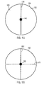
- the ball bladder of the embodiments has an outer wall 100, 150 and at least one inner wall 110, 160, 170.
- the embodiment of Figure 1A may have one inner wall whereas the ball bladder of Figure 1B may have two inner walls.
- each of the depicted inner walls may be built from multiple pieces which could each be regarded as an inner wall.
- the inner wall 160 may be provided as one piece whereas the left side and the right side of 170 can be provided separately as different inner walls.
- the ball bladder of Figure 1 B would include three inner walls.
- the ball bladder of Figure 1A is shown to have two chambers 120, 130 separated by the inner wall 110.
- the ball bladder shown in Figure 1B is shown to have four chambers. It is noted that further embodiments exist where the number of chambers deviates from two or four. In fact, the invention is not restricted to a certain number of chambers, and embodiments may exist which have one, three, five or any other number of chambers.
- a device 140, 180 is located at a center position of the ball bladder.
- the center position of the ball bladder is the same as the center position of the ball having incorporated the ball bladder. It is however noted that where the center position of the ball bladder deviates from the center position of the ball, embodiments may exist where the device is located at a center position of the ball bladder, and other embodiments exist where the device is positioned at a center position of the ball. In this regard, "center position" may refer to the geometric center or to the mass center.
- Figures 1A and 1 B depict a device 140, 180 to be of a circular shape. This is not intended to be limiting the invention to devices of only this shape. Rather, the device may have any size or shape.
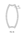
- the outer wall 100, 150 of the ball bladder may be built by attaching together multiple pieces.
- Figure 2A depicts an embodiment of a quarter piece 200 which may be used to manufacture an outer wall.
- four quarter pieces 200 are used, and these four quarter pieces are attached together at the longer portions of the welded seams 210.
- two end pieces 400, 410 can be used as shown in Figure 4 .
- One of the end pieces may have a valve which is necessary to pump air into the ball bladder.
- the inner wall 220 has a number of air holes 230 to allow the chambers to exchange air whenever the ball is deformed. It is noted that the invention is not limited to a certain number of air holes, and embodiments may exist having zero or only one air hole in an inner wall. It is however noted that the number of ten to fifteen air holes is found to be particularly advantageous with respect to allowing an efficient air exchange between the chambers with substantially no negative influence on the mechanical properties of the inner wall of the ball bladder.
- the inner wall 220 of Figure 2B schematically shows the center position 250 where mounting means to hold a device may be positioned. As described in more detail below, the inner wall may also have an opening in the center position.
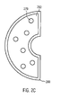
- Figure 2C shows another embodiment of an inner wall 260 having air holes 270 and a center position.
- the inner wall 260 of Figure 2C may have similar seams 280.
- the inner wall 260 is substantially half the size of the inner wall 220 of Figure 2B .
- an even number of the inner wall 260 may be preferably used to manufacture a ball bladder according to an embodiment.
- two pieces of the inner wall 260 shown in Figure 2C are necessary.
- the number of inner walls may be odd.
- FIG. 2C illustrates a recess at the center position.
- This recess may be provided to create a free space for the device and the mounting means if the mounting means are affixed to another inner wall, such as the inner wall 220.
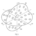
- Figure 3 illustrates a center cross arrangement where the inner wall 220 and two pieces of the inner wall 260 are mounted together.
- the inner wall 220 will have mounting means (not shown in Figure 3 , but described in more detail below) at the center position, i.e., at the point where the three axes 300, 310, 320 coincide.
- the device may be a passive device such as a permanent magnet, or an active device.
- the device may be a chip having data processing capabilities, or a sensor such as a magnetic or electric field sensor.
- the device may also have radio transmitter, receiver or transceiver capabilities in any suitable electromagnetic frequency range, including that of wireless transmissions.
- the device may be capable of performing near-field, far-field, short-range, mobile or satellite communications.
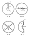
- Figures 5A, 5B and 5C depict exemplary arrangements of active devices 500 which have electrically conductive wires 510, 540 and/or antennas 530, 540 mounted on an inner wall such as the inner wall 220 shown in Figure 2B .
- the wires may be used to feed electric power to the device.
- the device may include a battery which can be charged through the wires 510.
- the wires have some connections 520 which may be positioned at one of the end pieces 400, 410 of the outer wall of the ball bladder.
- the electric wires may be also used to read out data from the device.
- the device may include one or more sensors which collect data during a sports game.
- data may include one or more of the following: the position of the ball, its velocity, acceleration, momentum and/or spin.
- Figures 5B and 5C depict devices 500 having antennas 530, 540.
- the antennas may be RFID, Bluetooth, or WLAN antennas or antennas of any other type.
- Figures 5B and 5C show antennas having two or four symmetrical parts, other embodiments exist where antennas have only one part or consist of three, five or any other number of symmetrical or asymmetrical parts. If the antenna has symmetrical parts, preferred embodiments position these parts in a symmetrical manner as shown in Figures 5B and 5C . If the antenna consists of only one part, this part may preferably be of a circular shape and positioned around the device.
- the ball bladder of some of the embodiments may have seams to connect the various bladder parts of the outer wall and/or inner wall.
- the elasticity of the seams may be optimized with respect to the desired ball jump capabilities or with respect to other mechanical properties of the ball or ball bladder.
- the number, size, type and/or position of any wire may be optimized together with the seams' elasticity. This may also be the case with antennas.
- Figure 6 depicts an example where an electrically conductive wire 600 is placed along a welded seam. In further embodiments, not all parts of the wire need to be placed along a welded seam.
- the inner end 620 of the wire 600 is prepared to be connected to the device, while one or more of the other ends 610 of the wire 600 may, in an embodiment, be connected to some electric contacts, similar to 520 shown in Figure 5A .
- Figures 5A, 5B, 5C and 6 depict various wire/antenna arrangements, but this is not intended to limit the invention. Further wire/antenna arrangements are possible in other embodiments. It is further noted that combinations of the depicted or the other possible embodiments may be made as well.
- a ball bladder may have electric wires for power feeding and/or sensor functionalities in addition to antennas, or an electrical wire may also have antenna functionality.
- FIG. 7A to 7D embodiments are depicted of how the mounting means can be realized in certain embodiments.
- the inner wall 700 has affixed a pocket 710, which may be manufactured by seaming a cover piece with welded seam 720.
- the pocket 710 has an opening through which a device can be inserted when manufacturing the ball bladder. In Figure 7A , this opening is located on the right side of the pocket.
- Figure 7B is a cross-sectional view of the single side pocket.
- the cover 730 is located at the upper side of the inner wall to form the pocket.
- Figure 7C depicts another embodiment having two pockets 740, 750, one on each side of the inner wall.
- the device is intended to be placed within this opening 760.
- the device can be inserted from both sides of the inner wall, i.e., via pocket 740 or alternatively, via pocket 750.
- Figure 7D depicts a further embodiment of a dual pocket ball bladder where the pocket on the upper side of the inner wall has an opening 770 directed to the right side whereas the pocket on the bottom side of the inner wall has an opening 780 directed downwards.
- the openings 770, 780 of both pockets are directed 90 degrees apart from each other. It is noted that other embodiments exist where the openings of the pockets are directed generally towards non-opposite sides. Having positioned the pockets in this way has the advantage of facilitating the manufacturing process, as it reduces the risk of the device slipping out of the pocket of the opposite side by mistake when pushing the device too much into the pocket.
- the various pieces of the inner and outer walls of the ball bladder as well as the mounting means, such as pockets, may be attached together using welded seams.
- the device may be additionally or alternatively mounted on TPU (thermo plastic elastomeric) material and glued at the center of the bladder.
- TPU thermo plastic elastomeric
- Fuller Ultraflex 4817 E glue can be used for this purpose.
- the bladder may then be sealed by means of a glued TPU sticker, which is heated up to, e.g., 50 °C.
Applications Claiming Priority (1)
| Application Number | Priority Date | Filing Date | Title |
|---|---|---|---|
| US30238510P | 2010-02-08 | 2010-02-08 |
Publications (1)
| Publication Number | Publication Date |
|---|---|
| EP2353666A1 true EP2353666A1 (de) | 2011-08-10 |
Family
ID=43920985
Family Applications (1)
| Application Number | Title | Priority Date | Filing Date |
|---|---|---|---|
| EP11000822A Withdrawn EP2353666A1 (de) | 2010-02-08 | 2011-02-02 | Ballblase mit Haltevorrichtung für ein Gerät |
Country Status (1)
| Country | Link |
|---|---|
| EP (1) | EP2353666A1 (de) |
Cited By (3)
| Publication number | Priority date | Publication date | Assignee | Title |
|---|---|---|---|---|
| CN106730666A (zh) * | 2017-02-07 | 2017-05-31 | 广东荣承体育用品制造有限公司 | 智能足球的内胆结构及其制作方法 |
| EP3299068A1 (de) * | 2016-09-27 | 2018-03-28 | Gengee Technology Co., Ltd. | Intelligenter ball mit mehreren airbags und herstellungsverfahren dafür |
| US10806972B1 (en) * | 2019-09-23 | 2020-10-20 | Yi Ching Lin | Ball with sensor |
Citations (4)
| Publication number | Priority date | Publication date | Assignee | Title |
|---|---|---|---|---|
| DE3918038C2 (de) | 1989-06-02 | 1992-03-19 | Sportartikelfabrik Karl Uhl Gmbh, 7460 Balingen, De | |
| WO2004026411A1 (en) * | 2002-09-17 | 2004-04-01 | Cruciani, Gabriele | Goal detection equipment for football |
| DE10361826A1 (de) * | 2003-12-30 | 2005-07-28 | Johannes Katz | Sportball, insbesondere Fussball |
| EP1637192A1 (de) * | 2004-09-17 | 2006-03-22 | adidas International Marketing B.V. | Blase |
-
2011
- 2011-02-02 EP EP11000822A patent/EP2353666A1/de not_active Withdrawn
Patent Citations (4)
| Publication number | Priority date | Publication date | Assignee | Title |
|---|---|---|---|---|
| DE3918038C2 (de) | 1989-06-02 | 1992-03-19 | Sportartikelfabrik Karl Uhl Gmbh, 7460 Balingen, De | |
| WO2004026411A1 (en) * | 2002-09-17 | 2004-04-01 | Cruciani, Gabriele | Goal detection equipment for football |
| DE10361826A1 (de) * | 2003-12-30 | 2005-07-28 | Johannes Katz | Sportball, insbesondere Fussball |
| EP1637192A1 (de) * | 2004-09-17 | 2006-03-22 | adidas International Marketing B.V. | Blase |
Cited By (3)
| Publication number | Priority date | Publication date | Assignee | Title |
|---|---|---|---|---|
| EP3299068A1 (de) * | 2016-09-27 | 2018-03-28 | Gengee Technology Co., Ltd. | Intelligenter ball mit mehreren airbags und herstellungsverfahren dafür |
| CN106730666A (zh) * | 2017-02-07 | 2017-05-31 | 广东荣承体育用品制造有限公司 | 智能足球的内胆结构及其制作方法 |
| US10806972B1 (en) * | 2019-09-23 | 2020-10-20 | Yi Ching Lin | Ball with sensor |
Similar Documents
| Publication | Publication Date | Title |
|---|---|---|
| CN103943945B (zh) | 手表天线及设有该手表天线的手表 | |
| US10396432B2 (en) | Antenna-integrated radio frequency module | |
| KR101958864B1 (ko) | 액체 금속을 이용한 안테나 장치 및 그를 이용하는 휴대 단말기 | |
| US10553345B2 (en) | Coil device and apparatus including the same | |
| CN110168804A (zh) | 用于可穿戴电子设备和导电壳体的缝隙天线设计的方法 | |
| US20120120573A1 (en) | Handle integrated motion capture element mount | |
| US7922097B2 (en) | SIM card IC module and SIM card | |
| JP2020072960A (ja) | ボール、特にゴルフボール、およびボールと通信可能な電子装置 | |
| US20170194711A1 (en) | Antenna device and electronic apparatus | |
| EP2353666A1 (de) | Ballblase mit Haltevorrichtung für ein Gerät | |
| US10707556B2 (en) | Antenna-integrated radio frequency module | |
| EP3983096B1 (de) | Sportball mit einer in einem stossdämpfenden träger untergebrachten elektronik | |
| CA3030288A1 (en) | Planar flexible rf tag and charging device | |
| US11394121B2 (en) | Nonplanar complementary patch antenna and associated methods | |
| AU2019246839B2 (en) | Folded uwb monopole antenna for body mounted transmitter and manufacturing method | |
| TWI568081B (zh) | 天線裝置及其無線通訊系統 | |
| CN110266172A (zh) | 线性振动致动器 | |
| US8749440B2 (en) | Antenna and mobile terminal including the same | |
| CN101601165B (zh) | 用于小型便携式通信装置的天线元件 | |
| US20170125904A1 (en) | Communication device | |
| CN208955181U (zh) | 天线组件和移动设备 | |
| CN116325357A (zh) | Uwb天线和包括其的电子装置 | |
| KR101946529B1 (ko) | 안테나 장치 | |
| EP3301821B1 (de) | Antenne für eine nfc-vorrichtung sowie nfc-vorrichtung | |
| KR102565875B1 (ko) | 무선 전력 송수신용 안테나 모듈 |
Legal Events
| Date | Code | Title | Description |
|---|---|---|---|
| PUAI | Public reference made under article 153(3) epc to a published international application that has entered the european phase |
Free format text: ORIGINAL CODE: 0009012 |
|
| AK | Designated contracting states |
Kind code of ref document: A1 Designated state(s): AL AT BE BG CH CY CZ DE DK EE ES FI FR GB GR HR HU IE IS IT LI LT LU LV MC MK MT NL NO PL PT RO RS SE SI SK SM TR |
|
| AX | Request for extension of the european patent |
Extension state: BA ME |
|
| 17P | Request for examination filed |
Effective date: 20111027 |
|
| GRAP | Despatch of communication of intention to grant a patent |
Free format text: ORIGINAL CODE: EPIDOSNIGR1 |
|
| RIC1 | Information provided on ipc code assigned before grant |
Ipc: A63B 41/02 20060101ALI20131025BHEP Ipc: A63B 41/00 20060101AFI20131025BHEP |
|
| INTG | Intention to grant announced |
Effective date: 20131202 |
|
| STAA | Information on the status of an ep patent application or granted ep patent |
Free format text: STATUS: THE APPLICATION IS DEEMED TO BE WITHDRAWN |
|
| 18D | Application deemed to be withdrawn |
Effective date: 20140415 |