EP2353551B1 - Coronary artery vascular stent with medicine carrying slots - Google Patents
Coronary artery vascular stent with medicine carrying slots Download PDFInfo
- Publication number
- EP2353551B1 EP2353551B1 EP09824395.9A EP09824395A EP2353551B1 EP 2353551 B1 EP2353551 B1 EP 2353551B1 EP 09824395 A EP09824395 A EP 09824395A EP 2353551 B1 EP2353551 B1 EP 2353551B1
- Authority
- EP
- European Patent Office
- Prior art keywords
- drug
- wave
- stent
- slots
- vascular stent
- Prior art date
- Legal status (The legal status is an assumption and is not a legal conclusion. Google has not performed a legal analysis and makes no representation as to the accuracy of the status listed.)
- Active
Links
Images



Classifications
-
- A—HUMAN NECESSITIES
- A61—MEDICAL OR VETERINARY SCIENCE; HYGIENE
- A61F—FILTERS IMPLANTABLE INTO BLOOD VESSELS; PROSTHESES; DEVICES PROVIDING PATENCY TO, OR PREVENTING COLLAPSING OF, TUBULAR STRUCTURES OF THE BODY, e.g. STENTS; ORTHOPAEDIC, NURSING OR CONTRACEPTIVE DEVICES; FOMENTATION; TREATMENT OR PROTECTION OF EYES OR EARS; BANDAGES, DRESSINGS OR ABSORBENT PADS; FIRST-AID KITS
- A61F2/00—Filters implantable into blood vessels; Prostheses, i.e. artificial substitutes or replacements for parts of the body; Appliances for connecting them with the body; Devices providing patency to, or preventing collapsing of, tubular structures of the body, e.g. stents
- A61F2/82—Devices providing patency to, or preventing collapsing of, tubular structures of the body, e.g. stents
- A61F2/86—Stents in a form characterised by the wire-like elements; Stents in the form characterised by a net-like or mesh-like structure
- A61F2/90—Stents in a form characterised by the wire-like elements; Stents in the form characterised by a net-like or mesh-like structure characterised by a net-like or mesh-like structure
- A61F2/91—Stents in a form characterised by the wire-like elements; Stents in the form characterised by a net-like or mesh-like structure characterised by a net-like or mesh-like structure made from perforated sheets or tubes, e.g. perforated by laser cuts or etched holes
- A61F2/915—Stents in a form characterised by the wire-like elements; Stents in the form characterised by a net-like or mesh-like structure characterised by a net-like or mesh-like structure made from perforated sheets or tubes, e.g. perforated by laser cuts or etched holes with bands having a meander structure, adjacent bands being connected to each other
-
- A—HUMAN NECESSITIES
- A61—MEDICAL OR VETERINARY SCIENCE; HYGIENE
- A61F—FILTERS IMPLANTABLE INTO BLOOD VESSELS; PROSTHESES; DEVICES PROVIDING PATENCY TO, OR PREVENTING COLLAPSING OF, TUBULAR STRUCTURES OF THE BODY, e.g. STENTS; ORTHOPAEDIC, NURSING OR CONTRACEPTIVE DEVICES; FOMENTATION; TREATMENT OR PROTECTION OF EYES OR EARS; BANDAGES, DRESSINGS OR ABSORBENT PADS; FIRST-AID KITS
- A61F2/00—Filters implantable into blood vessels; Prostheses, i.e. artificial substitutes or replacements for parts of the body; Appliances for connecting them with the body; Devices providing patency to, or preventing collapsing of, tubular structures of the body, e.g. stents
- A61F2/82—Devices providing patency to, or preventing collapsing of, tubular structures of the body, e.g. stents
- A61F2/86—Stents in a form characterised by the wire-like elements; Stents in the form characterised by a net-like or mesh-like structure
- A61F2/90—Stents in a form characterised by the wire-like elements; Stents in the form characterised by a net-like or mesh-like structure characterised by a net-like or mesh-like structure
- A61F2/91—Stents in a form characterised by the wire-like elements; Stents in the form characterised by a net-like or mesh-like structure characterised by a net-like or mesh-like structure made from perforated sheets or tubes, e.g. perforated by laser cuts or etched holes
-
- A—HUMAN NECESSITIES
- A61—MEDICAL OR VETERINARY SCIENCE; HYGIENE
- A61F—FILTERS IMPLANTABLE INTO BLOOD VESSELS; PROSTHESES; DEVICES PROVIDING PATENCY TO, OR PREVENTING COLLAPSING OF, TUBULAR STRUCTURES OF THE BODY, e.g. STENTS; ORTHOPAEDIC, NURSING OR CONTRACEPTIVE DEVICES; FOMENTATION; TREATMENT OR PROTECTION OF EYES OR EARS; BANDAGES, DRESSINGS OR ABSORBENT PADS; FIRST-AID KITS
- A61F2/00—Filters implantable into blood vessels; Prostheses, i.e. artificial substitutes or replacements for parts of the body; Appliances for connecting them with the body; Devices providing patency to, or preventing collapsing of, tubular structures of the body, e.g. stents
- A61F2/82—Devices providing patency to, or preventing collapsing of, tubular structures of the body, e.g. stents
- A61F2/86—Stents in a form characterised by the wire-like elements; Stents in the form characterised by a net-like or mesh-like structure
- A61F2/90—Stents in a form characterised by the wire-like elements; Stents in the form characterised by a net-like or mesh-like structure characterised by a net-like or mesh-like structure
- A61F2/91—Stents in a form characterised by the wire-like elements; Stents in the form characterised by a net-like or mesh-like structure characterised by a net-like or mesh-like structure made from perforated sheets or tubes, e.g. perforated by laser cuts or etched holes
- A61F2/915—Stents in a form characterised by the wire-like elements; Stents in the form characterised by a net-like or mesh-like structure characterised by a net-like or mesh-like structure made from perforated sheets or tubes, e.g. perforated by laser cuts or etched holes with bands having a meander structure, adjacent bands being connected to each other
- A61F2002/91508—Stents in a form characterised by the wire-like elements; Stents in the form characterised by a net-like or mesh-like structure characterised by a net-like or mesh-like structure made from perforated sheets or tubes, e.g. perforated by laser cuts or etched holes with bands having a meander structure, adjacent bands being connected to each other the meander having a difference in amplitude along the band
-
- A—HUMAN NECESSITIES
- A61—MEDICAL OR VETERINARY SCIENCE; HYGIENE
- A61F—FILTERS IMPLANTABLE INTO BLOOD VESSELS; PROSTHESES; DEVICES PROVIDING PATENCY TO, OR PREVENTING COLLAPSING OF, TUBULAR STRUCTURES OF THE BODY, e.g. STENTS; ORTHOPAEDIC, NURSING OR CONTRACEPTIVE DEVICES; FOMENTATION; TREATMENT OR PROTECTION OF EYES OR EARS; BANDAGES, DRESSINGS OR ABSORBENT PADS; FIRST-AID KITS
- A61F2/00—Filters implantable into blood vessels; Prostheses, i.e. artificial substitutes or replacements for parts of the body; Appliances for connecting them with the body; Devices providing patency to, or preventing collapsing of, tubular structures of the body, e.g. stents
- A61F2/82—Devices providing patency to, or preventing collapsing of, tubular structures of the body, e.g. stents
- A61F2/86—Stents in a form characterised by the wire-like elements; Stents in the form characterised by a net-like or mesh-like structure
- A61F2/90—Stents in a form characterised by the wire-like elements; Stents in the form characterised by a net-like or mesh-like structure characterised by a net-like or mesh-like structure
- A61F2/91—Stents in a form characterised by the wire-like elements; Stents in the form characterised by a net-like or mesh-like structure characterised by a net-like or mesh-like structure made from perforated sheets or tubes, e.g. perforated by laser cuts or etched holes
- A61F2/915—Stents in a form characterised by the wire-like elements; Stents in the form characterised by a net-like or mesh-like structure characterised by a net-like or mesh-like structure made from perforated sheets or tubes, e.g. perforated by laser cuts or etched holes with bands having a meander structure, adjacent bands being connected to each other
- A61F2002/9155—Adjacent bands being connected to each other
- A61F2002/91558—Adjacent bands being connected to each other connected peak to peak
-
- A—HUMAN NECESSITIES
- A61—MEDICAL OR VETERINARY SCIENCE; HYGIENE
- A61F—FILTERS IMPLANTABLE INTO BLOOD VESSELS; PROSTHESES; DEVICES PROVIDING PATENCY TO, OR PREVENTING COLLAPSING OF, TUBULAR STRUCTURES OF THE BODY, e.g. STENTS; ORTHOPAEDIC, NURSING OR CONTRACEPTIVE DEVICES; FOMENTATION; TREATMENT OR PROTECTION OF EYES OR EARS; BANDAGES, DRESSINGS OR ABSORBENT PADS; FIRST-AID KITS
- A61F2230/00—Geometry of prostheses classified in groups A61F2/00 - A61F2/26 or A61F2/82 or A61F9/00 or A61F11/00 or subgroups thereof
- A61F2230/0002—Two-dimensional shapes, e.g. cross-sections
- A61F2230/0028—Shapes in the form of latin or greek characters
- A61F2230/0054—V-shaped
-
- A—HUMAN NECESSITIES
- A61—MEDICAL OR VETERINARY SCIENCE; HYGIENE
- A61F—FILTERS IMPLANTABLE INTO BLOOD VESSELS; PROSTHESES; DEVICES PROVIDING PATENCY TO, OR PREVENTING COLLAPSING OF, TUBULAR STRUCTURES OF THE BODY, e.g. STENTS; ORTHOPAEDIC, NURSING OR CONTRACEPTIVE DEVICES; FOMENTATION; TREATMENT OR PROTECTION OF EYES OR EARS; BANDAGES, DRESSINGS OR ABSORBENT PADS; FIRST-AID KITS
- A61F2250/00—Special features of prostheses classified in groups A61F2/00 - A61F2/26 or A61F2/82 or A61F9/00 or A61F11/00 or subgroups thereof
- A61F2250/0058—Additional features; Implant or prostheses properties not otherwise provided for
- A61F2250/0067—Means for introducing or releasing pharmaceutical products into the body
- A61F2250/0068—Means for introducing or releasing pharmaceutical products into the body the pharmaceutical product being in a reservoir
Definitions
- the present invention pertains to the field of medical instruments, and it relates to a type of coronary vascular stent, especially a type of coronary artery vascular stent with drug-carrying slots.
- Common metallic stents are produced from 316L stainless steel, cobalt chromium alloy or nickel titanium alloy. Although these metallic stents meet the requirements of mechanical properties in the structure, they contact directly with blood after implanted into the human body, which stimulates the rejection capability of the human body to foreign matters, causing hyperplasia of the vascular intima tissue and the smooth muscle cells. Moreover, as the stent surface gets rougher, the possibility of cruor occurring gets larger. Metallic stents also release heavy metal ions under blood circulation, and these heavy metal ions would promote happening of thrombus. These factors lead to happening of restenosis after the stent implantation.
- drug-eluting stents have been developed as required.
- the drug is coated onto the metallic stent through some processing, and after the stent is implanted into the body, the drug can be released at the region of lesion, maintaining a releasing period, which effectively prevents post-operative restenosis in-stent.
- most of the present drug stents are coated with drug on both the interior and exterior metallic surfaces, so as to render high drug concentration inside the blood vessel and high releasing rate, and the releasing direction cannot be controlled effectively, making some of the drug can not be absorbed by the blood vessel wall.
- the coating herein will easily fall off during the process of stent propelling and expansion. The fallen drug mass flows with blood, and easily causes thrombus, leading to new damages.
- the vascular stent normally has a net tube shaped structure, comprising a plurality of main structure struts with sinusoidal waveform structure.
- the adjacent main structure rods are connected there between with connecting rods, and the exterior surface of the main structure rod has drug-carrying slots.
- This vascular stent with drug-carrying slots can improve the distribution of the drug in the blood vessel, increase the adhesion capability of the coating on the stent, and prolong the functioning time of the drug.
- the length of the drug-carrying slots is very important.
- the length is too short, it will cause nonhomogeneous distribution of the drug in the slots, and the drug loading cannot meet the requirements for effective cure of lesion; if the length is too long, it would surely affect the mechanical property of the stent, causing fracture of the stent.
- Such vascular stents having a plurality of main structure struts with sinusoidal waveform structure and having drug carrying slots are known for example from US 2007/0123974 A1 , from WO 03/047463 A1 or from US 2005/0055080 A1 .
- the first technical problem to be solved in the present invention is to provide a type of coronary vascular stent with drug-carrying slots, and in this type of vascular stent, the mechanical property of the stent would not be affected for having the drug-carrying slots.
- the second technical problem to be solved in the present invention is to provide a type of coronary vascular stent with drug-carrying slots, and such vascular stent can increase the capture capability of the sample application system with respect to the center position of the slots, and increase the quality of the stent drug dripping.
- the third technical problem to be solved in the present invention is to provide a type of coronary vascular stent with drug-carrying slots, and such vascular stent can increase the support force to the plaque of lesion.
- a type of coronary artery vascular stent with drug-carrying slots which is comprised of a plurality of main supporting unit rings and connecting rods at the near-end, far-end and in the intermediate portions of the stent, the main supporting unit ring consists of a plurality of unit waves, the wave rod exterior surface of which has drug-carrying slots, characterized in that the accumulative slot-length of the drug-carrying slots covers 60%-75% of the wave rod length of the main supporting unit rings.
- the accumulative slot-length of the drug-carrying slots covers 64%-70% of the wave rod length of the main supporting unit rings.
- the accumulative slot-length of the drug-carrying slots covers more than 75% of the wave rod length of the main supporting unit rings, fracture phenomenon would happen in the vascular stent in the limit expansion fracture experiment and fatigue test; if the accumulative slot-length of the drug-carrying slots covers less than 60% of the wave rod length of the main supporting unit rings, it causes nonhomogeneous distribution of the drug in the slots, and the drug-carrying amount cannot meet the requirements for effective cure of lesion.
- the unit wave consists of a reinforcement ring, a straight rod segment and a transition segment connecting the reinforcement ring and the straight rod segment.
- the straight rod segment and the transition segment are slightly wider than the reinforcement ring.
- the straight rod segment and the transition segment are 5-15% wider than the reinforcement ring.
- the unit waves at the near-end and the far-end of the stent render a "U" shape
- the connecting rods between the main supporting unit rings at the near-end and the far-end and the adjacent support unit rings are connected at the wave crests of two adjacent "U" shaped unit waves, rendering "crest to crest” connection.
- the connecting rods at the near-end and the far-end of the stent are "n" shaped connecting rods.
- the unit wave in the intermediate portion of the stent is comprised of two types of wave shapes, wherein the wave shape length of one type is obviously shorter than that of the other type.
- the wave shape length of the one type is 25-35% shorter than that of the other type.
- the intermediate portion of the stent can be considered to be comprised of "U” shaped wave and "W” shaped wave for the convenience of stent recognition.
- the connecting rods between the adjacent central main supporting wave rods are connected from the wave crest of the "U” shaped wave to the wave base of the "W” shaped wave, rendering "crest to base” connection.
- the connecting rods in the intermediate portion of the stent are made by connecting the "S" shaped curved portion to the straight portion, wherein the straight portion is completely vertical to the longitudinal axis of the stent.
- the adjacent main supporting unit rings are connected by the connecting rods to form a cylinder-shaped circular stent.
- the drug-carrying slots are mainly located at the straight rod segment of the unit waves, or at the straight rod segment and the transition segment, or extend to a small segment of the reinforcement ring.
- the reinforcement ring may be a circular arc with a radian larger than 180 degrees.
- each unit wave only has one drug-carrying slot.
- the drug-carrying slots can be strip-shaped.
- the drug-carrying slots can be a non-penetrable slots.
- the width of the drug-carrying slots can be 45%-60% of the width of the unit wave straight rod segment.
- the depth of the drug-carrying slots can be 15%-30% of the thickness of the stent.
- the drug-carrying slots can be made by laser cutting technique.
- the vascular stent is made of cobalt based alloy, stainless steel or magnesium alloy.
- the vascular stent with drug-carrying slots in the present invention besides those advantages of improving the drug distribution in the blood vessel, increasing the adhesion of the coating on the stent, and extending the functioning time of the drug, have the following advantages:
- the stent structure of a first embodiment is comprised of a plurality of main supporting unit rings 1, 8 and connecting rods 6, 4 that connect the unit rings, wherein the main supporting unit ring are comprised of a plurality of unit waves.
- the unit wave is comprised of reinforcement ring 9 of the circular arc segment, straight rod segment 20 and the transition segments 21 and 22 connecting the reinforcement rings and the straight rod segment, and the exterior surface of the unit wave rod has drug-carrying slots 2 which can be loaded with drug.
- the main supporting unit rings 1 and 10 at the near-end and the far-end are comprised of a plurality of "U" shaped waves 3, and the connecting rods between adjacent unit rings are "n" shaped connecting rods 6, which are connected at the wave crests of two adjacent "U” shaped unit waves, rendering "crest to crest” connection.
- the main supporting unit rings 8 in the intermediate portion of the stent are comprised of two types of wave shapes, wherein the first type of wave shape 11 corresponds to the first type of supporting structure 12, while the second type of wave shape 13 corresponds to the second type of supporting structure 14, and the first type of wave shape has a length obviously shorter than that of the second type of wave shape.
- the intermediate portion of the stent can also be considered to be comprised of "U” shaped waves 15 and "W” shaped waves 17.
- the connecting rod 16 between the adjacent intermediate units are connected from the wave crest of the "U” shaped wave to the wave base of the "W” shaped wave, rendering "crest to base” connection.
- the connecting rod 16 is made by connecting a "S" shaped curved portion 19 to the straight portion 18, wherein the straight segment is completely vertical to the longitudinal axis of the stent.
- the width of the straight rod segment in the unit wave of the main supporting unit ring in the first embodiment is 96 ⁇ m, and the width of the reinforcement ring is 91 ⁇ m, and the straight rod segment is slightly wider than the reinforcement ring by approximately 5%.
- the transition segment connects the straight rod segment and the reinforcement ring smoothly.
- the first type of wave shape is 25% shorter than the second type of wave shape.
- the thickness of the stent is 100 ⁇ m, and the drug-carrying slots are cut out by laser cutting technique with a slots width of 55 ⁇ m and a depth of 30 ⁇ m, and the accumulative slot-length covers 60% of the total wave rod length of the main supporting unit rings.
- drug-carrying slots 2 is located at the straight rod segment 20 and the transition segments 21, 22 of the stent main supporting unit wave rod, but the tops of the slots are not in contact with the edges of the transition segment.
- the stent structural design, the width and thickness of the unit wave rod, the width and depth of the drug-carrying slots of the second embodiment are the same as those of the first embodiment, and the length and the position of the slots is shown in Figure 6 , and the accumulative slot-length covers 64% of the total wave rod length of the main supporting unit rings.
- the drug-carrying slots 2 are notched on the straight rod segment 20 and the transition segments 21, 22 of the stent main supporting wave rod, but there is not any slot on the reinforcement ring 9.
- the width of the straight rod segment and the reinforcement ring are the same as that of the first embodiment.
- the stent structural design of the third embodiment is the same as that of the first embodiment, only with the difference of the size of the unit wave, and Figure 7 is a partial structural schematic diagram of the intermediate portion.
- the width of the straight rod segment is 107 ⁇ m
- the width of the reinforcement ring is still 91 ⁇ m
- the straight rod segment is 15% wider than the reinforcement ring.
- the wave shape of the first type 11 is 35% shorter than the wave shape of the second type.
- the thickness of the stent is 100 ⁇ m
- the drug-carrying slots have a width of 55 ⁇ m and a depth of 25 ⁇ m.
- the accumulative slot-length is the same as the second embodiment, and it still covers 64% of the total wave rod length of the main supporting unit rings, and the notching position does not extend to the reinforcement ring 9.
- the length and position of the slots in the fourth embodiment is shown in Figure 8 , and the drug-carrying slots 2 are located at the straight rod segment 20 and the transition segments 21, 22 of the stent main supporting wave rod, while extending to a small segment of the reinforcement ring, and the accumulative slot-length covers 70% of the total wave rod length of the main supporting unit rings.
- the stent structural design and size are the same as the first embodiment.
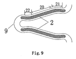
- the length and position of the slots of the fifth embodiment is shown in Figure 9 , and the drug-carrying slots 2 are located at the straight rod segment 20 and the transition segments 21, 22 of the stent main supporting wave rod, while extending to the reinforcement ring, but not reaching the center of the reinforcement ring, and the accumulative slot-length covers 75% of the total wave rod length of the main supporting unit rings.
- the other sizes of the stent are also the same as the first embodiment.
- the slot-length is 60%, 64%, 70% and 75%
- the drug is distributed homogeneously throughout the whole slots, and during the dripping process, no drug overflows to the interior surface, exterior surface and the side surface outside the stent slots, and the drug-carrying amount meets the requirements.
- the slot-length is below 60%, the drug is not distributed homogeneously, and the drug-carrying amount could not meet the requirements for effective cure of lesion, either.
- the straight rod segment and the transition segment are wider than the reinforcement ring, in the case of a certain width of the slots, when dripping drug to the stent drug-carrying slots, on one hand, the catching capability of the sample application system with respect to the center position of the slots is increased, and on the other hand, when there is not enough time for the drug solvent to evaporate, the drug tends to overflow, at this time because the slot-edge is relatively wide, the adhesion of the drug to the slot-wall is increased, which avoids the drug to overflow to the interior and exterior surfaces and the side surface outside the stent slots, increasing the quality of the stent drug dripping.
- the straight rod segment and the transition segment are 5-15% wider than the reinforcement ring. When the width of straight rod segment is a percent below 5% wider than the width of the reinforcement ring, the drug would overflow.
- the unit wave in the intermediate portion of the stent of the present invention is comprised of two types of wave shapes, wherein a design with one type of wave shape having a length shorter than that of the other type of wave shape can increase the support force to pathogenic plaque.
- Compressed-grasping experiments are performed on the first and third embodiments, after compressed-grasping, no contact is observed between the stent wave rod and the connecting rod, and the balloon was not broken.
- on type of wave shape length is 25-35% shorter than the other type of wave shape length, and when this range is below 25%, when compressed-grasping the stent, the S shaped connecting rod 16 would be in contact with the wave crest of the shorter wave 11, crashing the balloon and causing safety risks; while this range is above 35%, the mesh area of the stent is increased to some extent, and the covering area of metal decreases, the supporting ability to pathogenic plaque decreases.
Landscapes
- Health & Medical Sciences (AREA)
- Engineering & Computer Science (AREA)
- Biomedical Technology (AREA)
- Heart & Thoracic Surgery (AREA)
- Optics & Photonics (AREA)
- Cardiology (AREA)
- Oral & Maxillofacial Surgery (AREA)
- Transplantation (AREA)
- Physics & Mathematics (AREA)
- Vascular Medicine (AREA)
- Life Sciences & Earth Sciences (AREA)
- Animal Behavior & Ethology (AREA)
- General Health & Medical Sciences (AREA)
- Public Health (AREA)
- Veterinary Medicine (AREA)
- Media Introduction/Drainage Providing Device (AREA)
Description
- The present invention pertains to the field of medical instruments, and it relates to a type of coronary vascular stent, especially a type of coronary artery vascular stent with drug-carrying slots.
- Sigwart succeeded in implementing the first surgery of coronary artery vascular stent in 1987. After that, coronary artery stent has been widely accepted as the second milestone in the history of interventional therapy of coronary heart diseases.
- Common metallic stents are produced from 316L stainless steel, cobalt chromium alloy or nickel titanium alloy. Although these metallic stents meet the requirements of mechanical properties in the structure, they contact directly with blood after implanted into the human body, which stimulates the rejection capability of the human body to foreign matters, causing hyperplasia of the vascular intima tissue and the smooth muscle cells. Moreover, as the stent surface gets rougher, the possibility of cruor occurring gets larger. Metallic stents also release heavy metal ions under blood circulation, and these heavy metal ions would promote happening of thrombus. These factors lead to happening of restenosis after the stent implantation.
- In this case, drug-eluting stents have been developed as required. The drug is coated onto the metallic stent through some processing, and after the stent is implanted into the body, the drug can be released at the region of lesion, maintaining a releasing period, which effectively prevents post-operative restenosis in-stent. However, most of the present drug stents are coated with drug on both the interior and exterior metallic surfaces, so as to render high drug concentration inside the blood vessel and high releasing rate, and the releasing direction cannot be controlled effectively, making some of the drug can not be absorbed by the blood vessel wall. Besides, at the places where the stent shape changes relatively largely, the coating herein will easily fall off during the process of stent propelling and expansion. The fallen drug mass flows with blood, and easily causes thrombus, leading to new damages.
- So far there are already vascular stent with drug-carrying slots on the market, and the vascular stent normally has a net tube shaped structure, comprising a plurality of main structure struts with sinusoidal waveform structure. The adjacent main structure rods are connected there between with connecting rods, and the exterior surface of the main structure rod has drug-carrying slots. This vascular stent with drug-carrying slots can improve the distribution of the drug in the blood vessel, increase the adhesion capability of the coating on the stent, and prolong the functioning time of the drug. However, the length of the drug-carrying slots is very important. If the length is too short, it will cause nonhomogeneous distribution of the drug in the slots, and the drug loading cannot meet the requirements for effective cure of lesion; if the length is too long, it would surely affect the mechanical property of the stent, causing fracture of the stent.
- Such vascular stents having a plurality of main structure struts with sinusoidal waveform structure and having drug carrying slots are known for example from
US 2007/0123974 A1 , fromWO 03/047463 A1 US 2005/0055080 A1 . - Therefore, the first technical problem to be solved in the present invention is to provide a type of coronary vascular stent with drug-carrying slots, and in this type of vascular stent, the mechanical property of the stent would not be affected for having the drug-carrying slots.
- The second technical problem to be solved in the present invention is to provide a type of coronary vascular stent with drug-carrying slots, and such vascular stent can increase the capture capability of the sample application system with respect to the center position of the slots, and increase the quality of the stent drug dripping.
- The third technical problem to be solved in the present invention is to provide a type of coronary vascular stent with drug-carrying slots, and such vascular stent can increase the support force to the plaque of lesion.
- These technical problems can be solved through the following technical solution: provide a type of coronary artery vascular stent with drug-carrying slots, which is comprised of a plurality of main supporting unit rings and connecting rods at the near-end, far-end and in the intermediate portions of the stent, the main supporting unit ring consists of a plurality of unit waves, the wave rod exterior surface of which has drug-carrying slots, characterized in that the accumulative slot-length of the drug-carrying slots covers 60%-75% of the wave rod length of the main supporting unit rings.
- Preferably, the accumulative slot-length of the drug-carrying slots covers 64%-70% of the wave rod length of the main supporting unit rings.
- According to the present invention, if the accumulative slot-length of the drug-carrying slots covers more than 75% of the wave rod length of the main supporting unit rings, fracture phenomenon would happen in the vascular stent in the limit expansion fracture experiment and fatigue test; if the accumulative slot-length of the drug-carrying slots covers less than 60% of the wave rod length of the main supporting unit rings, it causes nonhomogeneous distribution of the drug in the slots, and the drug-carrying amount cannot meet the requirements for effective cure of lesion.
- The unit wave consists of a reinforcement ring, a straight rod segment and a transition segment connecting the reinforcement ring and the straight rod segment.
- The straight rod segment and the transition segment are slightly wider than the reinforcement ring. The straight rod segment and the transition segment are 5-15% wider than the reinforcement ring.
- The unit waves at the near-end and the far-end of the stent render a "U" shape, and the connecting rods between the main supporting unit rings at the near-end and the far-end and the adjacent support unit rings are connected at the wave crests of two adjacent "U" shaped unit waves, rendering "crest to crest" connection.
- The connecting rods at the near-end and the far-end of the stent are "n" shaped connecting rods.
- The unit wave in the intermediate portion of the stent is comprised of two types of wave shapes, wherein the wave shape length of one type is obviously shorter than that of the other type. The wave shape length of the one type is 25-35% shorter than that of the other type.
- After the stent has been cut from the tubing, the intermediate portion of the stent can be considered to be comprised of "U" shaped wave and "W" shaped wave for the convenience of stent recognition. The connecting rods between the adjacent central main supporting wave rods are connected from the wave crest of the "U" shaped wave to the wave base of the "W" shaped wave, rendering "crest to base" connection.
- The connecting rods in the intermediate portion of the stent are made by connecting the "S" shaped curved portion to the straight portion, wherein the straight portion is completely vertical to the longitudinal axis of the stent.
- According to the present invention, the adjacent main supporting unit rings are connected by the connecting rods to form a cylinder-shaped circular stent.
- According to the specific requirements, the drug-carrying slots are mainly located at the straight rod segment of the unit waves, or at the straight rod segment and the transition segment, or extend to a small segment of the reinforcement ring.
- The reinforcement ring may be a circular arc with a radian larger than 180 degrees.
- The wave rod exterior surface of each unit wave only has one drug-carrying slot.
- The drug-carrying slots can be strip-shaped.
- The drug-carrying slots can be a non-penetrable slots.
- The width of the drug-carrying slots can be 45%-60% of the width of the unit wave straight rod segment.
- The depth of the drug-carrying slots can be 15%-30% of the thickness of the stent.
- The drug-carrying slots can be made by laser cutting technique.
- The vascular stent is made of cobalt based alloy, stainless steel or magnesium alloy.
- Compared to the current techniques, the vascular stent with drug-carrying slots in the present invention, besides those advantages of improving the drug distribution in the blood vessel, increasing the adhesion of the coating on the stent, and extending the functioning time of the drug, have the following advantages:
- (1) When the accumulative slot-length of the drug-carrying slots covers 60-75% of the wave rod length of the main supporting unit rings, the mechanical properties of the vascular stent with the drug-carrying slots is maintained well. If the drug-carrying slots are too long, the notching position would be extended excessively to the wave crest of the reinforcement ring. When the stent expands, as the expansion pressure increases, the notching portion of the reinforcement ring has smaller sectional area and larger stress than that of the non-notching portion, and fracture phenomenon happens at the interface between the notching and non-notching portions. If the slots cover the whole main supporting wave rod, it will make the stent become thinner and lead to corrosion fracture and fatigue fracture in the stent. Therefore, the reasonable design of the slot-length in the present invention not only reduces the risks of stent expansion fracture, but also increases its capabilities of resistance to corrosion and fatigue fracture.
- (2) In the unit waves constituting the stent main supporting wave rods of the present invention, because the straight rod segment and the transition segment are slightly wider than the reinforcement ring, in the case of a certain width of the slots, when dripping drug to the stent drug-carrying slots, on one hand, the catching capability of the sample application system with respect to the center position of the slots is increased, and on the other hand, when there is not enough time for the drug solvent to evaporate, the drug tends to overflow, at this time because the slots edge is relatively wide, the adhesion of the drug to the slots wall is increased, which avoids the drug to overflow to the interior and exterior surfaces and the side surface outside the stent slots, increasing the quality of the stent drug dripping.
- (3) The unit waves in the intermediate portion of the stent are comprised of two types of waves with different wave shape lengths, and a connecting rod is connected from the wave crest of a main supporting unit wave to the wave base of the adjacent main supporting unit wave, rendering "crest to base" connection, which makes the distance between the two adjacent main supporting unit rings become smaller, thereby decreases the mesh area of the stent, and increases the support to the plaque of lesion.
- (4) The special design of the stent connecting rod structure increases the flexibility of the stent, and the "n" shaped connecting rod at both ends of the stent has a certain elastic force, which can decrease the axial contracting; the connecting rod is made by connecting the "S" shaped curved segment to the straight segment, wherein the straight segment is vertical to the longitudinal axis of the stent, increasing the longitudinal flexibility of the stent. When the stent passes through bended blood vessel, the curved portion and the straight portion of the connecting rod would allow the stent to bend longitudinally, and the ability of the stent to cure lesion is highly increased.
-
-
Figure 1 is a schematic diagram of the planar structure of the stent expanded in the axial direction according to a first embodiment of the present invention; -
Figure 2 is a structural schematic diagram of the near-end and the far-end main supporting unit rings in the stent according to the first embodiment of the present invention; -
Figure 3 is a structural schematic diagram of the main supporting unit rings in the intermediate portion in the stent according to the first embodiment of the present invention; -
Figure 4 is a partial structural schematic diagram of the intermediate portion in the stent according to the first embodiment of the present invention; -
Figure 5 is a partial structural schematic diagram of the notching position according to the first embodiment of the present invention; -
Figure 6 is a partial structural schematic diagram of the notching position according to a second embodiment of the present invention; -
Figure 7 is a partial structural schematic diagram of the intermediate portion in the stent according to a third embodiment of the present invention; -
Figure 8 is a partial structural schematic diagram of the notching position according to a fourth embodiment of the present invention; -
Figure 9 is a partial structural schematic diagram of the notching position according to a fifth embodiment of the present invention; - The specific embodiments of the present invention are described in combination with the drawings as follows.
- In combination with that shown in
Figure 1 ,Figure 2 and Figure 3 , the stent structure of a first embodiment is comprised of a plurality of main supporting unit rings 1, 8 and connectingrods 6, 4 that connect the unit rings, wherein the main supporting unit ring are comprised of a plurality of unit waves. As shown inFigure 5 , the unit wave is comprised ofreinforcement ring 9 of the circular arc segment,straight rod segment 20 and thetransition segments slots 2 which can be loaded with drug. - In the axial direction of the stent, the main supporting unit rings 1 and 10 at the near-end and the far-end are comprised of a plurality of "U" shaped
waves 3, and the connecting rods between adjacent unit rings are "n" shaped connecting rods 6, which are connected at the wave crests of two adjacent "U" shaped unit waves, rendering "crest to crest" connection. As shown inFigure 4 , the main supporting unit rings 8 in the intermediate portion of the stent are comprised of two types of wave shapes, wherein the first type ofwave shape 11 corresponds to the first type of supportingstructure 12, while the second type ofwave shape 13 corresponds to the second type of supportingstructure 14, and the first type of wave shape has a length obviously shorter than that of the second type of wave shape. When the stent is under the grasping status, the two types of wave shapes would come closer to each other respectively. The intermediate portion of the stent can also be considered to be comprised of "U" shaped waves 15 and "W" shaped waves 17. The connectingrod 16 between the adjacent intermediate units are connected from the wave crest of the "U" shaped wave to the wave base of the "W" shaped wave, rendering "crest to base" connection. The connectingrod 16 is made by connecting a "S" shapedcurved portion 19 to thestraight portion 18, wherein the
straight segment is completely vertical to the longitudinal axis of the stent. - The width of the straight rod segment in the unit wave of the main supporting unit ring in the first embodiment is 96 µm, and the width of the reinforcement ring is 91 µm, and the straight rod segment is slightly wider than the reinforcement ring by approximately 5%. The transition segment connects the straight rod segment and the reinforcement ring smoothly. In the intermediate portion of the stent, the first type of wave shape is 25% shorter than the second type of wave shape. The thickness of the stent is 100 µm, and the drug-carrying slots are cut out by laser cutting technique with a slots width of 55 µm and a depth of 30 µm, and the accumulative slot-length covers 60% of the total wave rod length of the main supporting unit rings. As shown in
Figure 5 , drug-carryingslots 2 is located at thestraight rod segment 20 and thetransition segments - The stent structural design, the width and thickness of the unit wave rod, the width and depth of the drug-carrying slots of the second embodiment are the same as those of the first embodiment, and the length and the position of the slots is shown in
Figure 6 , and the accumulative slot-length covers 64% of the total wave rod length of the main supporting unit rings. The drug-carryingslots 2 are notched on thestraight rod segment 20 and thetransition segments reinforcement ring 9. The width of the straight rod segment and the reinforcement ring are the same as that of the first embodiment. - The stent structural design of the third embodiment is the same as that of the first embodiment, only with the difference of the size of the unit wave, and
Figure 7 is a partial structural schematic diagram of the intermediate portion. In the unit wave, the width of the straight rod segment is 107 µm, and the width of the reinforcement ring is still 91 µm, and the straight rod segment is 15% wider than the reinforcement ring. In the intermediate portion of the stent, the wave shape of thefirst type 11 is 35% shorter than the wave shape of the second type. The thickness of the stent is 100 µm, and the drug-carrying slots have a width of 55 µm and a depth of 25 µm. The accumulative slot-length is the same as the second embodiment, and it still covers 64% of the total wave rod length of the main supporting unit rings, and the notching position does not extend to thereinforcement ring 9. - The length and position of the slots in the fourth embodiment is shown in
Figure 8 , and the drug-carryingslots 2 are located at thestraight rod segment 20 and thetransition segments - The length and position of the slots of the fifth embodiment is shown in
Figure 9 , and the drug-carryingslots 2 are located at thestraight rod segment 20 and thetransition segments
accumulative slot-length covers 75% of the total wave rod length of the main supporting unit rings. The other sizes of the stent are also the same as the first embodiment. - Limit expansion fracture experiment, fatigue test and drug dripping homogenicity test are performed on the above-mentioned embodiments respectively. The experiments show that when stents of the above-mentioned first, second, third, and fourth embodiments are designed as stents with a diameter of 4.0 mm and a length of 18 mm, when a balloon with a diameter of 6.0 mm and a length of 18 mm is used to expand the stents, no fracture happens on the stents when the slot-length is 60%, 64%, 70%, 75% after keeping the pressure at 12 atm for 60 s. However, with the same structural design, when the accumulative slot-length covers 80% and 100% of the wave rod length of the main supporting unit rings, fracture happens when still using the same method to expand the stents. The experiments also show that when doing 10 years fatigue lifetime tests on stents of five different slot-lengths, no deformation and fracture happen to the stents whose slot-length covers 60%, 64%, 70% and 75% of the total wave rod length, while fracture happens to both the stents whose slot-length covers 80% and 100% of the total wave rod length.
- When doing drug dripping experiments, when the slot-length is 60%, 64%, 70% and 75%, the drug is distributed homogeneously throughout the whole slots, and during the dripping process, no drug overflows to the interior surface, exterior surface and the side surface outside the stent slots, and the drug-carrying amount meets the requirements. When the slot-length is below 60%, the drug is not distributed homogeneously, and the drug-carrying amount could not meet the requirements for effective cure of lesion, either.
- Meanwhile, in the unit waves constituting the stent main supporting wave rod, because the straight rod segment and the transition segment are wider than the reinforcement ring, in the case of a certain width of the slots, when dripping drug to the stent drug-carrying slots, on one hand, the catching capability of the sample application system with respect to the center position of the slots is increased, and on the other hand, when there is not enough time for the drug solvent to evaporate, the drug tends to overflow, at this time because the slot-edge is relatively wide, the adhesion of the drug to the slot-wall is increased, which avoids the drug to overflow to the interior and exterior surfaces and the side surface outside the stent slots, increasing the quality of the stent drug dripping. Preferably, the straight rod segment and the transition segment are 5-15% wider than the reinforcement ring. When the width of straight rod segment is a percent below 5% wider than the width of the reinforcement ring, the drug would overflow.
- The unit wave in the intermediate portion of the stent of the present invention is comprised of two types of wave shapes, wherein a design with one type of wave shape having a length shorter than that of the other type of wave shape can increase the support force to pathogenic plaque. Compressed-grasping experiments are performed on the first and third embodiments, after compressed-grasping, no contact is observed between the stent wave rod and the connecting rod, and the balloon was not broken. Preferably, on type of wave shape length is 25-35% shorter
than the other type of wave shape length, and when this range is below 25%, when compressed-grasping the stent, the S shaped connectingrod 16 would be in contact with the wave crest of theshorter wave 11, crashing the balloon and causing safety risks; while this range is above 35%, the mesh area of the stent is increased to some extent, and the covering area of metal decreases, the supporting ability to pathogenic plaque decreases. - Therefore, the designs of the slot-length and the structure of the stents of the present invention are reasonable and safe.
Claims (10)
- A coronary artery vascular stent with drug-carrying slots, comprised of a plurality of main supporting unit rings (1,8) and connecting rods (4,6) at the proximal, distal and in the intermediate portion of the stent, said main supporting unit ring (1,8) consists of a plurality of unit waves, the wave rod exterior surface of the unit waves has drug-carrying slots (2),
the accumulative slot-length of the drug-carrying slots (2) covers 60%-75% of the total wave rod length of the main supporting unit rings (1,8), characterized in that
each of the unit wave consists of a reinforcement ring (9), a straight rod segment (20) and a transition segment (21,22) connecting the reinforcement ring (9) and the straight rod segment (20), and the straight rod segment (20) and the transition segment (21,22) are 5-15% wider than the reinforcement ring (9),
the unit wave in the intermediate portion of the stent is comprised of two types of wave shapes (11,13), wherein the wave shape length of the one type is 25-35% shorter than that of the other type. - The vascular stent according to claim 1, characterized in that the accumulative slot-length of the drug-carrying slots (2) covers 64%-70% of the total wave rod length of the main supporting unit rings (1,8).
- The vascular stent according to claim 1, characterized in that the adjacent main supporting unit rings (1,2; and 5,8) are connected by the connecting rods (6; and 4) to form a cylinder-shaped circular stent.
- The vascular stent according to claim 1 or 2, characterized in that the drug-carrying slots (2) are located at the straight rod segment (20), or at the straight rod segment (20) and the transition segment (21,22), or extend to a small segment of the reinforcement ring (9).
- The vascular stent according to claim 1, characterized in that the reinforcement ring (9) is a circular arc with a radian larger than 180 degrees.
- The vascular stent according to claim 1, characterized in that the wave rod exterior surface of each unit wave only has one drug-carrying slot (2).
- The vascular stent according to claim 1 or 2, characterized in that the drug-carrying slots (2) are strip-shaped.
- The vascular stent according to claim 1 or 2, characterized in that the drug-carrying slots (2) are non-penetrable slots.
- The vascular stent according to claim 1 or 2, characterized in that the drug-carrying slots (2) are made by laser cutting technique.
- The vascular stent according to claim 1, characterized in that the vascular stent is made of cobalt based alloy, stainless steel or magnesium alloy.
Applications Claiming Priority (2)
| Application Number | Priority Date | Filing Date | Title |
|---|---|---|---|
| CN200810202191.4A CN101732114B (en) | 2008-11-04 | 2008-11-04 | Coronary artery stent with medicine carrying grooves |
| PCT/CN2009/074754 WO2010051740A1 (en) | 2008-11-04 | 2009-11-02 | Coronary artery vascular stent with medicine carrying slots |
Publications (3)
| Publication Number | Publication Date |
|---|---|
| EP2353551A1 EP2353551A1 (en) | 2011-08-10 |
| EP2353551A4 EP2353551A4 (en) | 2015-09-02 |
| EP2353551B1 true EP2353551B1 (en) | 2016-10-26 |
Family
ID=42152490
Family Applications (1)
| Application Number | Title | Priority Date | Filing Date |
|---|---|---|---|
| EP09824395.9A Active EP2353551B1 (en) | 2008-11-04 | 2009-11-02 | Coronary artery vascular stent with medicine carrying slots |
Country Status (5)
| Country | Link |
|---|---|
| US (1) | US9089446B2 (en) |
| EP (1) | EP2353551B1 (en) |
| JP (2) | JP5959854B2 (en) |
| CN (1) | CN101732114B (en) |
| WO (1) | WO2010051740A1 (en) |
Cited By (1)
| Publication number | Priority date | Publication date | Assignee | Title |
|---|---|---|---|---|
| US10786376B2 (en) | 2015-09-10 | 2020-09-29 | Bentley Innomed Gmbh | Expandable vascular stent |
Families Citing this family (31)
| Publication number | Priority date | Publication date | Assignee | Title |
|---|---|---|---|---|
| MX2013001445A (en) * | 2010-08-02 | 2013-03-12 | Cordis Corp | Flexible stent having protruding hinges. |
| KR101544263B1 (en) | 2012-08-28 | 2015-08-12 | 연세대학교 산학협력단 | Wire stent for easy endothelial cellularization |
| US9980835B2 (en) * | 2013-10-22 | 2018-05-29 | Orbusneich Medical Inc. | Medical device for implantation into luminal structures incorporating corrugated structural elements |
| US9895243B2 (en) | 2014-07-17 | 2018-02-20 | W. L. Gore & Associates, Inc. | Stent having adjacent elements connected by narrow flexible webs |
| US9381103B2 (en) * | 2014-10-06 | 2016-07-05 | Abbott Cardiovascular Systems Inc. | Stent with elongating struts |
| CN104287870B (en) * | 2014-10-10 | 2017-03-29 | 先健科技(深圳)有限公司 | Intraluminal stent |
| CN104814820A (en) * | 2015-03-25 | 2015-08-05 | 苏州固基电子科技有限公司 | Vascular support for preventing vascular restenosis |
| CN104814818A (en) * | 2015-04-24 | 2015-08-05 | 苏州固基电子科技有限公司 | Intravascular stent |
| CN105030391B (en) * | 2015-07-07 | 2018-07-20 | 南昌大学 | A kind of intravascular stent with Surface Texture |
| CN106236342B (en) * | 2016-08-23 | 2024-04-30 | 深圳信立泰医疗器械股份有限公司 | Implantable complete biological absorbable vascular polymer stent |
| CN107049571A (en) * | 2017-05-12 | 2017-08-18 | 微创神通医疗科技(上海)有限公司 | A kind of vertebral artery stent and preparation method thereof |
| CN107088110A (en) * | 2017-06-15 | 2017-08-25 | 微创神通医疗科技(上海)有限公司 | Vertebral artery stent and preparation method thereof |
| US10517747B2 (en) | 2017-06-19 | 2019-12-31 | Cook Medical Technologies Llc | Cannula cut stent with closed end cell geometry |
| JP2021510617A (en) | 2018-01-16 | 2021-04-30 | シントラ メディカル エルエルシーSintra Medical Llc | Stent with increased flexibility |
| US10575973B2 (en) * | 2018-04-11 | 2020-03-03 | Abbott Cardiovascular Systems Inc. | Intravascular stent having high fatigue performance |
| CN111904676A (en) * | 2019-05-10 | 2020-11-10 | 上海微创医疗器械(集团)有限公司 | Degradable drug-loaded stent and manufacturing method thereof |
| WO2021011819A1 (en) | 2019-07-16 | 2021-01-21 | Sintra Medical Llc | Stents with increased flexibility |
| CN112972083B (en) * | 2019-12-17 | 2022-11-11 | 北京迈迪顶峰医疗科技股份有限公司 | Pulmonary artery stent for children |
| CN113116616B (en) * | 2019-12-31 | 2022-07-22 | 元心科技(深圳)有限公司 | Absorbable instrument |
| CN111529152A (en) * | 2020-05-15 | 2020-08-14 | 上海君联医疗设备有限公司 | a vascular stent |
| CN111603284A (en) * | 2020-06-16 | 2020-09-01 | 湖南华耀百奥医疗科技有限公司 | Absorbable zinc-based alloy drug-loaded stent |
| US12496200B2 (en) * | 2020-06-19 | 2025-12-16 | Massachusetts Institute Of Technology | Kirigami-inspired stents for sustained local delivery of therapeutics |
| CN111789704A (en) * | 2020-07-01 | 2020-10-20 | 上海微创医疗器械(集团)有限公司 | bracket |
| CN111789705A (en) * | 2020-07-01 | 2020-10-20 | 上海微创医疗器械(集团)有限公司 | bracket |
| CN113967117A (en) * | 2020-07-23 | 2022-01-25 | 赛诺医疗科学技术股份有限公司 | Degradable magnesium alloy drug eluting stent |
| CN113545898B (en) * | 2021-08-31 | 2022-09-16 | 西北有色金属研究院 | Vascular stent structure with uniform stress |
| CN114587728B (en) * | 2022-04-06 | 2024-09-27 | 江苏理工学院 | A circular vascular stent |
| CN115568990A (en) * | 2022-08-08 | 2023-01-06 | 江苏大学 | Vascular stent with axial zero Poisson ratio structure |
| CN117224297B (en) * | 2023-11-13 | 2024-02-13 | 太原理工大学 | A reverse combined structure lower limb arterial stent |
| CN119235517B (en) * | 2024-12-04 | 2025-06-17 | 上海璟佳山医疗科技有限公司 | A vascular stent |
| CN119655936B (en) * | 2025-02-20 | 2025-06-13 | 北京航空航天大学 | A degradable vascular stent |
Family Cites Families (55)
| Publication number | Priority date | Publication date | Assignee | Title |
|---|---|---|---|---|
| CA2380683C (en) * | 1991-10-28 | 2006-08-08 | Advanced Cardiovascular Systems, Inc. | Expandable stents and method for making same |
| US20040225347A1 (en) * | 2000-06-05 | 2004-11-11 | Lang G. David | Intravascular stent with increasing coating retaining capacity |
| US5922020A (en) * | 1996-08-02 | 1999-07-13 | Localmed, Inc. | Tubular prosthesis having improved expansion and imaging characteristics |
| FR2764794B1 (en) * | 1997-06-20 | 1999-11-12 | Nycomed Lab Sa | EXPANDED TUBULAR DEVICE WITH VARIABLE THICKNESS |
| EP1017336B1 (en) * | 1997-09-24 | 2007-08-15 | Med Institute, Inc. | Radially expandable stent |
| US6042606A (en) * | 1997-09-29 | 2000-03-28 | Cook Incorporated | Radially expandable non-axially contracting surgical stent |
| US6129755A (en) * | 1998-01-09 | 2000-10-10 | Nitinol Development Corporation | Intravascular stent having an improved strut configuration |
| US6179867B1 (en) * | 1998-01-16 | 2001-01-30 | Advanced Cardiovascular Systems, Inc. | Flexible stent and method of use |
| US20010032011A1 (en) * | 1999-07-20 | 2001-10-18 | Stanford Ulf Harry | Expandable stent with array of relief cuts |
| US6379381B1 (en) * | 1999-09-03 | 2002-04-30 | Advanced Cardiovascular Systems, Inc. | Porous prosthesis and a method of depositing substances into the pores |
| EP1132058A1 (en) * | 2000-03-06 | 2001-09-12 | Advanced Laser Applications Holding S.A. | Intravascular prothesis |
| US6709451B1 (en) * | 2000-07-14 | 2004-03-23 | Norman Noble, Inc. | Channeled vascular stent apparatus and method |
| US6254632B1 (en) | 2000-09-28 | 2001-07-03 | Advanced Cardiovascular Systems, Inc. | Implantable medical device having protruding surface structures for drug delivery and cover attachment |
| US6764507B2 (en) * | 2000-10-16 | 2004-07-20 | Conor Medsystems, Inc. | Expandable medical device with improved spatial distribution |
| PT1328213E (en) * | 2000-10-16 | 2005-10-31 | Conor Medsystems Inc | EXPANSIVE MEDICAL DEVICE FOR THE ADMINISTRATION OF A BENEFICIAL AGENT |
| US6506437B1 (en) * | 2000-10-17 | 2003-01-14 | Advanced Cardiovascular Systems, Inc. | Methods of coating an implantable device having depots formed in a surface thereof |
| US6758859B1 (en) * | 2000-10-30 | 2004-07-06 | Kenny L. Dang | Increased drug-loading and reduced stress drug delivery device |
| US7056339B2 (en) * | 2001-04-20 | 2006-06-06 | The Board Of Trustees Of The Leland Stanford Junior University | Drug delivery platform |
| DE60120955T3 (en) | 2001-07-20 | 2015-06-25 | Cid S.P.A. | stent |
| EP1416884A4 (en) * | 2001-07-26 | 2007-03-07 | Avantec Vascular Corp | Delivery of therapeutic capable agents |
| US7578841B2 (en) * | 2001-09-24 | 2009-08-25 | Boston Scientific Scimed, Inc. | Stent with protruding branch portion for bifurcated vessels |
| US7014654B2 (en) * | 2001-11-30 | 2006-03-21 | Scimed Life Systems, Inc. | Stent designed for the delivery of therapeutic substance or other agents |
| JP2005524488A (en) * | 2002-05-08 | 2005-08-18 | アボット・ラボラトリーズ | Endoprosthesis with extended foot |
| US6969402B2 (en) * | 2002-07-26 | 2005-11-29 | Syntheon, Llc | Helical stent having flexible transition zone |
| CN2553820Y (en) * | 2002-08-07 | 2003-06-04 | 山东省医疗器械研究所 | Morphologic memory alloy internal support for human lumen |
| US7135038B1 (en) * | 2002-09-30 | 2006-11-14 | Advanced Cardiovascular Systems, Inc. | Drug eluting stent |
| US7169178B1 (en) * | 2002-11-12 | 2007-01-30 | Advanced Cardiovascular Systems, Inc. | Stent with drug coating |
| DE10261822A1 (en) * | 2002-12-20 | 2004-07-01 | Biotronik Meß- und Therapiegeräte GmbH & Co. Ingenieurbüro Berlin | Helix bridge connection |
| US7163555B2 (en) * | 2003-04-08 | 2007-01-16 | Medtronic Vascular, Inc. | Drug-eluting stent for controlled drug delivery |
| US7959665B2 (en) * | 2003-07-31 | 2011-06-14 | Abbott Cardiovascular Systems Inc. | Intravascular stent with inverted end rings |
| US20050055080A1 (en) * | 2003-09-05 | 2005-03-10 | Naim Istephanous | Modulated stents and methods of making the stents |
| US7763066B2 (en) * | 2004-07-28 | 2010-07-27 | Cook Incorporated | Stent with an end member having a lateral extension |
| DE102004045226B4 (en) * | 2004-09-17 | 2008-01-17 | Optiray Medizintechnik Gmbh | support prosthesis |
| CN1605366A (en) * | 2004-12-03 | 2005-04-13 | 北京美中双和医疗器械有限公司 | Vascular stent mounted with non penetrable slot or blind hole and its preparing method |
| CN2749469Y (en) * | 2004-12-03 | 2006-01-04 | 北京美中双和医疗器械有限公司 | Blood vessel stent with non-penetration groove or blind hole |
| US20070073385A1 (en) * | 2005-09-20 | 2007-03-29 | Cook Incorporated | Eluting, implantable medical device |
| KR100778020B1 (en) * | 2005-10-24 | 2007-11-28 | 사회복지법인 삼성생명공익재단 | Vascular stents for multiple drug loading and more effective drug release |
| US8545545B2 (en) * | 2006-10-18 | 2013-10-01 | Innovational Holdings Llc | Stent with flexible hinges |
| US7682388B2 (en) * | 2007-01-30 | 2010-03-23 | Medtronic Vascular, Inc. | Stent with longitudinal groove |
| CN201019862Y (en) * | 2007-04-06 | 2008-02-13 | 微创医疗器械(上海)有限公司 | A kind of vascular stent with drug-loading groove |
| US20090076591A1 (en) * | 2007-09-19 | 2009-03-19 | Boston Scientific Scimed, Inc. | Stent Design Allowing Extended Release of Drug and/or Enhanced Adhesion of Polymer to OD Surface |
| WO2009041664A1 (en) * | 2007-09-27 | 2009-04-02 | Terumo Kabushiki Kaisha | Stent and living organ dilator |
| US7722661B2 (en) * | 2007-12-19 | 2010-05-25 | Boston Scientific Scimed, Inc. | Stent |
| US20090287295A1 (en) * | 2008-05-13 | 2009-11-19 | Contiliano Joseph H | Method of Manufacturing a Polymeric Stent with a Hybrid Support Structure |
| US20100082096A1 (en) * | 2008-09-30 | 2010-04-01 | Boston Scientific Scimed, Inc. | Tailored Luminal & Abluminal Drug Elution |
| JP5273377B2 (en) * | 2009-03-19 | 2013-08-28 | 株式会社ジャパンディスプレイ | Multi-input single-output circuit and display device |
| US8425586B2 (en) * | 2009-09-02 | 2013-04-23 | Novostent Corporation | Vascular prosthesis with stress relief slots |
| US20110066227A1 (en) * | 2009-09-17 | 2011-03-17 | Boston Scientific Scimed, Inc. | Stent with Dynamic Drug Reservoirs |
| US20110070358A1 (en) * | 2009-09-20 | 2011-03-24 | Medtronic Vascular, Inc. | Method of forming hollow tubular drug eluting medical devices |
| US8562670B2 (en) * | 2010-04-01 | 2013-10-22 | Abbott Cardiovascular Systems Inc. | Implantable prosthesis with depot retention feature |
| CA2807119C (en) * | 2010-08-02 | 2017-08-01 | Cordis Corporation | Flexible helical stent having different helical regions |
| US8333801B2 (en) * | 2010-09-17 | 2012-12-18 | Medtronic Vascular, Inc. | Method of Forming a Drug-Eluting Medical Device |
| US10166128B2 (en) * | 2011-01-14 | 2019-01-01 | W. L. Gore & Associates. Inc. | Lattice |
| US9393136B2 (en) * | 2012-03-27 | 2016-07-19 | Medtronic Vascular, Inc. | Variable zone high metal to vessel ratio stent and method |
| US20150073535A1 (en) * | 2013-09-12 | 2015-03-12 | Abbott Cardiovascular Systems Inc. | Treatment of coronary artery lesions with a scaffold having vessel scaffold interactions that reduce or prevent angina |
-
2008
- 2008-11-04 CN CN200810202191.4A patent/CN101732114B/en active Active
-
2009
- 2009-11-02 EP EP09824395.9A patent/EP2353551B1/en active Active
- 2009-11-02 WO PCT/CN2009/074754 patent/WO2010051740A1/en not_active Ceased
- 2009-11-02 JP JP2011534991A patent/JP5959854B2/en active Active
- 2009-11-02 US US13/127,548 patent/US9089446B2/en active Active
-
2014
- 2014-11-10 JP JP2014228444A patent/JP2015062685A/en active Pending
Cited By (1)
| Publication number | Priority date | Publication date | Assignee | Title |
|---|---|---|---|---|
| US10786376B2 (en) | 2015-09-10 | 2020-09-29 | Bentley Innomed Gmbh | Expandable vascular stent |
Also Published As
| Publication number | Publication date |
|---|---|
| WO2010051740A1 (en) | 2010-05-14 |
| JP2015062685A (en) | 2015-04-09 |
| EP2353551A1 (en) | 2011-08-10 |
| JP2012507375A (en) | 2012-03-29 |
| CN101732114A (en) | 2010-06-16 |
| CN101732114B (en) | 2014-07-30 |
| EP2353551A4 (en) | 2015-09-02 |
| US20110238157A1 (en) | 2011-09-29 |
| US9089446B2 (en) | 2015-07-28 |
| JP5959854B2 (en) | 2016-08-02 |
Similar Documents
| Publication | Publication Date | Title |
|---|---|---|
| US9089446B2 (en) | Coronary artery vascular stent with medicine carrying slots | |
| EP2063824B1 (en) | Helical implant having different ends | |
| EP1871439B1 (en) | Hybrid biodegradable/non-biodegradable stent, delivery system and method of treating a vascular condition | |
| EP2939640B1 (en) | Highly flexible stent | |
| EP2656818B1 (en) | Absorbable blood vessel stent | |
| US20050182477A1 (en) | Intraluminal stent and graft | |
| WO2015192019A1 (en) | Biodegradable wire with central filament | |
| JP2009526572A (en) | Highly flexible stent and manufacturing method | |
| JP2013176576A (en) | Intravascular stent | |
| US20110238156A1 (en) | Flexible Stent Design | |
| US10864069B2 (en) | Stent with deflecting connector | |
| US20080140187A1 (en) | Anti-clotting, anti-microbial, anti-inflammatory medical stent | |
| CN201968866U (en) | Absorbable blood vessel support | |
| KR101841542B1 (en) | Stent having enhanced blood flow with shark skin-shaped strut | |
| WO2018143115A1 (en) | Bioabsorbable stent | |
| JP5267457B2 (en) | Stent | |
| WO2007040249A1 (en) | Stent to be placed in the living body | |
| JP6960110B2 (en) | Stent | |
| JP5610863B2 (en) | Stent and stent delivery catheter | |
| WO2011129917A1 (en) | Aspect ratio for stent strut design | |
| JP2016193186A (en) | Highly flexible stent |
Legal Events
| Date | Code | Title | Description |
|---|---|---|---|
| PUAI | Public reference made under article 153(3) epc to a published international application that has entered the european phase |
Free format text: ORIGINAL CODE: 0009012 |
|
| 17P | Request for examination filed |
Effective date: 20110601 |
|
| AK | Designated contracting states |
Kind code of ref document: A1 Designated state(s): AT BE BG CH CY CZ DE DK EE ES FI FR GB GR HR HU IE IS IT LI LT LU LV MC MK MT NL NO PL PT RO SE SI SK SM TR |
|
| DAX | Request for extension of the european patent (deleted) | ||
| RAP1 | Party data changed (applicant data changed or rights of an application transferred) |
Owner name: SHANGHAI MICROPORT MEDICAL (GROUP) CO., LTD. |
|
| RA4 | Supplementary search report drawn up and despatched (corrected) |
Effective date: 20150730 |
|
| RIC1 | Information provided on ipc code assigned before grant |
Ipc: A61F 2/915 20130101ALI20150724BHEP Ipc: A61F 2/91 20130101ALI20150724BHEP Ipc: A61F 2/82 20130101AFI20150724BHEP Ipc: A61M 31/00 20060101ALI20150724BHEP |
|
| GRAP | Despatch of communication of intention to grant a patent |
Free format text: ORIGINAL CODE: EPIDOSNIGR1 |
|
| RIC1 | Information provided on ipc code assigned before grant |
Ipc: A61M 31/00 20060101ALI20160517BHEP Ipc: A61F 2/82 20060101AFI20160517BHEP Ipc: A61F 2/91 20130101ALI20160517BHEP Ipc: A61F 2/915 20130101ALI20160517BHEP |
|
| INTG | Intention to grant announced |
Effective date: 20160602 |
|
| GRAS | Grant fee paid |
Free format text: ORIGINAL CODE: EPIDOSNIGR3 |
|
| GRAA | (expected) grant |
Free format text: ORIGINAL CODE: 0009210 |
|
| AK | Designated contracting states |
Kind code of ref document: B1 Designated state(s): AT BE BG CH CY CZ DE DK EE ES FI FR GB GR HR HU IE IS IT LI LT LU LV MC MK MT NL NO PL PT RO SE SI SK SM TR |
|
| REG | Reference to a national code |
Ref country code: GB Ref legal event code: FG4D |
|
| REG | Reference to a national code |
Ref country code: CH Ref legal event code: EP |
|
| REG | Reference to a national code |
Ref country code: AT Ref legal event code: REF Ref document number: 839458 Country of ref document: AT Kind code of ref document: T Effective date: 20161115 |
|
| REG | Reference to a national code |
Ref country code: IE Ref legal event code: FG4D |
|
| REG | Reference to a national code |
Ref country code: FR Ref legal event code: PLFP Year of fee payment: 8 |
|
| REG | Reference to a national code |
Ref country code: DE Ref legal event code: R096 Ref document number: 602009042011 Country of ref document: DE |
|
| REG | Reference to a national code |
Ref country code: LT Ref legal event code: MG4D |
|
| PG25 | Lapsed in a contracting state [announced via postgrant information from national office to epo] |
Ref country code: BE Free format text: LAPSE BECAUSE OF NON-PAYMENT OF DUE FEES Effective date: 20161130 Ref country code: LV Free format text: LAPSE BECAUSE OF FAILURE TO SUBMIT A TRANSLATION OF THE DESCRIPTION OR TO PAY THE FEE WITHIN THE PRESCRIBED TIME-LIMIT Effective date: 20161026 |
|
| REG | Reference to a national code |
Ref country code: NL Ref legal event code: MP Effective date: 20161026 |
|
| REG | Reference to a national code |
Ref country code: AT Ref legal event code: MK05 Ref document number: 839458 Country of ref document: AT Kind code of ref document: T Effective date: 20161026 |
|
| PG25 | Lapsed in a contracting state [announced via postgrant information from national office to epo] |
Ref country code: GR Free format text: LAPSE BECAUSE OF FAILURE TO SUBMIT A TRANSLATION OF THE DESCRIPTION OR TO PAY THE FEE WITHIN THE PRESCRIBED TIME-LIMIT Effective date: 20170127 Ref country code: NO Free format text: LAPSE BECAUSE OF FAILURE TO SUBMIT A TRANSLATION OF THE DESCRIPTION OR TO PAY THE FEE WITHIN THE PRESCRIBED TIME-LIMIT Effective date: 20170126 Ref country code: SE Free format text: LAPSE BECAUSE OF FAILURE TO SUBMIT A TRANSLATION OF THE DESCRIPTION OR TO PAY THE FEE WITHIN THE PRESCRIBED TIME-LIMIT Effective date: 20161026 Ref country code: LT Free format text: LAPSE BECAUSE OF FAILURE TO SUBMIT A TRANSLATION OF THE DESCRIPTION OR TO PAY THE FEE WITHIN THE PRESCRIBED TIME-LIMIT Effective date: 20161026 |
|
| PG25 | Lapsed in a contracting state [announced via postgrant information from national office to epo] |
Ref country code: IS Free format text: LAPSE BECAUSE OF FAILURE TO SUBMIT A TRANSLATION OF THE DESCRIPTION OR TO PAY THE FEE WITHIN THE PRESCRIBED TIME-LIMIT Effective date: 20170226 Ref country code: ES Free format text: LAPSE BECAUSE OF FAILURE TO SUBMIT A TRANSLATION OF THE DESCRIPTION OR TO PAY THE FEE WITHIN THE PRESCRIBED TIME-LIMIT Effective date: 20161026 Ref country code: PL Free format text: LAPSE BECAUSE OF FAILURE TO SUBMIT A TRANSLATION OF THE DESCRIPTION OR TO PAY THE FEE WITHIN THE PRESCRIBED TIME-LIMIT Effective date: 20161026 Ref country code: NL Free format text: LAPSE BECAUSE OF FAILURE TO SUBMIT A TRANSLATION OF THE DESCRIPTION OR TO PAY THE FEE WITHIN THE PRESCRIBED TIME-LIMIT Effective date: 20161026 Ref country code: FI Free format text: LAPSE BECAUSE OF FAILURE TO SUBMIT A TRANSLATION OF THE DESCRIPTION OR TO PAY THE FEE WITHIN THE PRESCRIBED TIME-LIMIT Effective date: 20161026 Ref country code: HR Free format text: LAPSE BECAUSE OF FAILURE TO SUBMIT A TRANSLATION OF THE DESCRIPTION OR TO PAY THE FEE WITHIN THE PRESCRIBED TIME-LIMIT Effective date: 20161026 Ref country code: AT Free format text: LAPSE BECAUSE OF FAILURE TO SUBMIT A TRANSLATION OF THE DESCRIPTION OR TO PAY THE FEE WITHIN THE PRESCRIBED TIME-LIMIT Effective date: 20161026 Ref country code: PT Free format text: LAPSE BECAUSE OF FAILURE TO SUBMIT A TRANSLATION OF THE DESCRIPTION OR TO PAY THE FEE WITHIN THE PRESCRIBED TIME-LIMIT Effective date: 20170227 Ref country code: BE Free format text: LAPSE BECAUSE OF FAILURE TO SUBMIT A TRANSLATION OF THE DESCRIPTION OR TO PAY THE FEE WITHIN THE PRESCRIBED TIME-LIMIT Effective date: 20161026 |
|
| REG | Reference to a national code |
Ref country code: CH Ref legal event code: PL |
|
| REG | Reference to a national code |
Ref country code: DE Ref legal event code: R097 Ref document number: 602009042011 Country of ref document: DE |
|
| PG25 | Lapsed in a contracting state [announced via postgrant information from national office to epo] |
Ref country code: SK Free format text: LAPSE BECAUSE OF FAILURE TO SUBMIT A TRANSLATION OF THE DESCRIPTION OR TO PAY THE FEE WITHIN THE PRESCRIBED TIME-LIMIT Effective date: 20161026 Ref country code: DK Free format text: LAPSE BECAUSE OF FAILURE TO SUBMIT A TRANSLATION OF THE DESCRIPTION OR TO PAY THE FEE WITHIN THE PRESCRIBED TIME-LIMIT Effective date: 20161026 Ref country code: MC Free format text: LAPSE BECAUSE OF FAILURE TO SUBMIT A TRANSLATION OF THE DESCRIPTION OR TO PAY THE FEE WITHIN THE PRESCRIBED TIME-LIMIT Effective date: 20161026 Ref country code: CZ Free format text: LAPSE BECAUSE OF FAILURE TO SUBMIT A TRANSLATION OF THE DESCRIPTION OR TO PAY THE FEE WITHIN THE PRESCRIBED TIME-LIMIT Effective date: 20161026 Ref country code: CH Free format text: LAPSE BECAUSE OF NON-PAYMENT OF DUE FEES Effective date: 20161130 Ref country code: LI Free format text: LAPSE BECAUSE OF NON-PAYMENT OF DUE FEES Effective date: 20161130 Ref country code: RO Free format text: LAPSE BECAUSE OF FAILURE TO SUBMIT A TRANSLATION OF THE DESCRIPTION OR TO PAY THE FEE WITHIN THE PRESCRIBED TIME-LIMIT Effective date: 20161026 Ref country code: EE Free format text: LAPSE BECAUSE OF FAILURE TO SUBMIT A TRANSLATION OF THE DESCRIPTION OR TO PAY THE FEE WITHIN THE PRESCRIBED TIME-LIMIT Effective date: 20161026 |
|
| PG25 | Lapsed in a contracting state [announced via postgrant information from national office to epo] |
Ref country code: SM Free format text: LAPSE BECAUSE OF FAILURE TO SUBMIT A TRANSLATION OF THE DESCRIPTION OR TO PAY THE FEE WITHIN THE PRESCRIBED TIME-LIMIT Effective date: 20161026 Ref country code: BG Free format text: LAPSE BECAUSE OF FAILURE TO SUBMIT A TRANSLATION OF THE DESCRIPTION OR TO PAY THE FEE WITHIN THE PRESCRIBED TIME-LIMIT Effective date: 20170126 |
|
| PLBE | No opposition filed within time limit |
Free format text: ORIGINAL CODE: 0009261 |
|
| STAA | Information on the status of an ep patent application or granted ep patent |
Free format text: STATUS: NO OPPOSITION FILED WITHIN TIME LIMIT |
|
| PG25 | Lapsed in a contracting state [announced via postgrant information from national office to epo] |
Ref country code: LU Free format text: LAPSE BECAUSE OF NON-PAYMENT OF DUE FEES Effective date: 20161130 |
|
| 26N | No opposition filed |
Effective date: 20170727 |
|
| REG | Reference to a national code |
Ref country code: FR Ref legal event code: PLFP Year of fee payment: 9 |
|
| PG25 | Lapsed in a contracting state [announced via postgrant information from national office to epo] |
Ref country code: SI Free format text: LAPSE BECAUSE OF FAILURE TO SUBMIT A TRANSLATION OF THE DESCRIPTION OR TO PAY THE FEE WITHIN THE PRESCRIBED TIME-LIMIT Effective date: 20161026 |
|
| PG25 | Lapsed in a contracting state [announced via postgrant information from national office to epo] |
Ref country code: CY Free format text: LAPSE BECAUSE OF FAILURE TO SUBMIT A TRANSLATION OF THE DESCRIPTION OR TO PAY THE FEE WITHIN THE PRESCRIBED TIME-LIMIT Effective date: 20161026 Ref country code: HU Free format text: LAPSE BECAUSE OF FAILURE TO SUBMIT A TRANSLATION OF THE DESCRIPTION OR TO PAY THE FEE WITHIN THE PRESCRIBED TIME-LIMIT; INVALID AB INITIO Effective date: 20091102 |
|
| PG25 | Lapsed in a contracting state [announced via postgrant information from national office to epo] |
Ref country code: MK Free format text: LAPSE BECAUSE OF FAILURE TO SUBMIT A TRANSLATION OF THE DESCRIPTION OR TO PAY THE FEE WITHIN THE PRESCRIBED TIME-LIMIT Effective date: 20161026 |
|
| PG25 | Lapsed in a contracting state [announced via postgrant information from national office to epo] |
Ref country code: MT Free format text: LAPSE BECAUSE OF NON-PAYMENT OF DUE FEES Effective date: 20161102 |
|
| PGFP | Annual fee paid to national office [announced via postgrant information from national office to epo] |
Ref country code: DE Payment date: 20251119 Year of fee payment: 17 |
|
| PGFP | Annual fee paid to national office [announced via postgrant information from national office to epo] |
Ref country code: GB Payment date: 20251121 Year of fee payment: 17 |
|
| PGFP | Annual fee paid to national office [announced via postgrant information from national office to epo] |
Ref country code: IT Payment date: 20251125 Year of fee payment: 17 |
|
| PGFP | Annual fee paid to national office [announced via postgrant information from national office to epo] |
Ref country code: FR Payment date: 20251124 Year of fee payment: 17 |
|
| PGFP | Annual fee paid to national office [announced via postgrant information from national office to epo] |
Ref country code: TR Payment date: 20251027 Year of fee payment: 17 |
|
| PGFP | Annual fee paid to national office [announced via postgrant information from national office to epo] |
Ref country code: IE Payment date: 20251121 Year of fee payment: 17 |