EP2352997B1 - Verfahren und systeme zur echtzeitcharakterisierung von lcm-partikelverstopfung und -rheologie - Google Patents
Verfahren und systeme zur echtzeitcharakterisierung von lcm-partikelverstopfung und -rheologie Download PDFInfo
- Publication number
- EP2352997B1 EP2352997B1 EP09765159.0A EP09765159A EP2352997B1 EP 2352997 B1 EP2352997 B1 EP 2352997B1 EP 09765159 A EP09765159 A EP 09765159A EP 2352997 B1 EP2352997 B1 EP 2352997B1
- Authority
- EP
- European Patent Office
- Prior art keywords
- fluid
- test cell
- gap
- conical
- lcm
- Prior art date
- Legal status (The legal status is an assumption and is not a legal conclusion. Google has not performed a legal analysis and makes no representation as to the accuracy of the status listed.)
- Active
Links
Images



Classifications
-
- G—PHYSICS
- G01—MEASURING; TESTING
- G01N—INVESTIGATING OR ANALYSING MATERIALS BY DETERMINING THEIR CHEMICAL OR PHYSICAL PROPERTIES
- G01N33/00—Investigating or analysing materials by specific methods not covered by groups G01N1/00 - G01N31/00
- G01N33/26—Oils; Viscous liquids; Paints; Inks
- G01N33/28—Oils, i.e. hydrocarbon liquids
- G01N33/2823—Raw oil, drilling fluid or polyphasic mixtures
-
- E—FIXED CONSTRUCTIONS
- E21—EARTH OR ROCK DRILLING; MINING
- E21B—EARTH OR ROCK DRILLING; OBTAINING OIL, GAS, WATER, SOLUBLE OR MELTABLE MATERIALS OR A SLURRY OF MINERALS FROM WELLS
- E21B21/00—Methods or apparatus for flushing boreholes, e.g. by use of exhaust air from motor
- E21B21/003—Means for stopping loss of drilling fluid
-
- G—PHYSICS
- G01—MEASURING; TESTING
- G01N—INVESTIGATING OR ANALYSING MATERIALS BY DETERMINING THEIR CHEMICAL OR PHYSICAL PROPERTIES
- G01N11/00—Investigating flow properties of materials, e.g. viscosity, plasticity; Analysing materials by determining flow properties
- G01N11/02—Investigating flow properties of materials, e.g. viscosity, plasticity; Analysing materials by determining flow properties by measuring flow of the material
- G01N11/04—Investigating flow properties of materials, e.g. viscosity, plasticity; Analysing materials by determining flow properties by measuring flow of the material through a restricted passage, e.g. tube, aperture
Definitions
- the present invention relates generally to methods and systems for material characterization and more particularly, to methods and systems for characterizing drilling fluids laden with LCM (Lost Circulation Material) and other solid materials.
- LCM Low Circulation Material
- Drilling operations play an important role when developing oil, gas or water wells or when mining for minerals and the like.
- Drilling fluids are commonly employed during the drilling operations and perform several important functions including, but not limited to, removing the cuttings from the well to the surface, controlling formation pressures, sealing permeable formations, minimizing formation damage, and cooling and lubricating the drill bit.
- LCM Lost Circulation Materials
- test cell for analyzing a fluid i.e. for measuring its viscosity
- US 3016734 A test cell for analyzing a fluid, i.e. for measuring its viscosity, is known from US 3016734 , wherein the test cell comprises a conical plug and a conical inner wall.
- the present invention provides a test cell defined in claim 1.
- the present invention provides a use defined in claim 9.
- the present invention provides a use defined in claim 12.
- the present invention provides a use defined in claim 16.
- the present invention provides a use defined claim 18. Further features are defined in the dependent claims.
- the present invention relates generally to methods and systems for material characterization and more particularly, to methods and systems for characterizing drilling fluids laden with LCM (Lost Circulation Material) and other solid materials.
- LCM Low Circulation Material
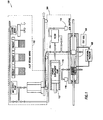
- Figure 1 depicts a characterization system 100 in accordance with an embodiment of the present invention.
- the characterization system 100 comprises a Pilot Testing Mixer (PTM) system 102, a LCM Stripping system 104 coupled to the PTM system 102 and a test cell 106 coupled to the LCM Stripping system 104.
- PTM Pilot Testing Mixer
- LCM Stripping system 104 coupled to the PTM system 102
- test cell 106 coupled to the LCM Stripping system 104.
- two components are deemed coupled to each other when fluid can flow from one to the other.
- coupling does not require that the components be directly connected.
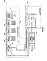
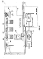
- FIGs 2A-2F depict the operation of the PTM system 102 where the drilling fluid to be analyzed is prepared.
- the PTM system 102 provides for addition and mixture of known quantities of LCM products to the drilling fluid.
- the PTM system 102 comprises a mixing tub 202 where the drilling fluid mixture is prepared.
- a mud supply pump 204 first adds the drilling mud to the mixing tub 202. Once the drilling mud is added to the mixing tub 202 ( Figure 2B ), the mixing tub 202 is placed in position for addition of different products from the product storage units 206, 208, 210.
- Product 1 (206), Product 2 (208) and Product 3 (210) are added to the mixing tub 202 as depicted in Figures 2C , 2D and 2E respectively.
- Products 1, 2, and 3 may be LCM or other materials suitable for addition to the drilling mud.
- a closure device 212 closes the mixing tub 202 and mixes the contents therein preparing a desired drilling fluid mixture in the mixing tub 202.
- Each of the mud supply pump 204 and the product storage units (206, 208, 210) are in effect removably couplable to the mixing tub 202 and can be coupled to the mixing tub 202 for addition of materials and then be removed.
- the closure device 212 is removably connectable to the mixing tub 202 and can be removed therefrom once it has performed the mixing operation.
- a pump 112 may then be used to deliver the drilling fluid mixture from the mixing tub 202 to the test cell 106.
- a positive displacement pump may be utilized to deliver the drilling fluid mixture to the test cell 106.
- FIG. 3 depicts an enlarged view of the test cell 106 which is where the measurements are actually made.
- the test cell 106 comprises a conical plug 302 coupled to an axial positioning device 304.
- the axial positioning device 304 may be used to axially position the conical plug 302 in a conical portion 306 formed by the test cell walls 308.
- the gap between the conical plug 302 and the test cell wall 308 simulates a fracture width. Different fracture widths may be simulated by moving the conical plug 302 in and out of the conical portion 306 in the direction indicated by the arrow 310.
- the geometry of the test cell wall 308 can be specified so as to simulate a particular desired fracture angle.
- the conical plug 302 and the test cell wall 308 can be utilized to simulate a range of fracture widths and angles providing the capability of analyzing the drilling fluid using a variable width slot. Stated otherwise, the slot width variability allows one to characterize the plugging and bridging of LCM products through a variety of user selectable fracture widths.
- the test cell also comprises a fluid inlet 312 and a fluid outlet 314.
- a brush 316 is coupled to the axial positioning device 304. Another cleaning device could be positioned so that it cleans the plug 302. The brush 316 is used to clean the test cell 106.
- the axial positioning device 304 may be used to move the brush 316 and perform a series of brush and rinse cycles to clean the test cell 106.
- a number of different materials may be used during the rinse cycle depending on the drilling fluid being tested.
- base oil or water may be used to rinse the test cell 106.
- the materials removed from the test cell 106 are transferred to a waste container 118.
- the test fluid is pumped through the test cell 106 at a constant rate while measuring the differential pressure across the simulated fracture at 108.
- the differential pressure may be measured in a number of ways, including, but not limited to pressure transducers which may be used in pairs or differential pressure transducers.
- the drilling fluid may be analyzed by setting the differential pressure and controlling the flow rate until plugging occurs.
- a positive displacement pump 110 may be utilized to control the flow of the drilling fluid through the test cell 106.
- Figure 1 depicts a positive displacement pump 110 configured as a syringe pump, as would be appreciated by those of ordinary skill in the art, with the benefit of this disclosure, any positive displacement pump capable of operating at the desired test pressure range may be used.
- Figure 4 depicts a simulated particle plugging and bridging in a test cell 106 in accordance with an embodiment of the present invention.
- the LCM solids that bridge and plug 402 the simulated fracture in the conical portion 306 between the conical plug 302 and the test cell wall 308 may form a seal anywhere along the flow path.
- the parallel slot mode where the walls defining the slot are substantially parallel to one another, most plugging is likely to occur at or very near the entrance of the simulated fracture.
- the plugging initiation location could be anywhere along the conical test cell wall 308, depending on Particle Size Distribution.
- ultrasonic methods may be used to determine the bridging and sealing efficiencies along the simulated fracture path if desired.
- Figure 5 depicts a graphical representation of the simulation of some expected test data from the test cell 106.
- the graph 500 depicts three different gap width scenarios labeled Gap Width 1 through Gap Width 3 based on the change in differential pressure over time.
- the Gap Width 1 curve represents a scenario where the fracture plugs quickly and fluid flow through the fracture is completely shut off.
- the Gap Width 2 curve represents a scenario where the fracture plugs more slowly, but does eventually plug.
- the flow continues and the fracture does not plug.
- the graph suggests that the fluid was treated sufficiently to plug the Gap Width 1. Because Gap Width 2 did plug but required more volume, the concentration of the ideal particle size was lower but yet at sufficient concentration to permit plugging. Therefore, the required particle availability could be established.
- the test cell 106 may be used to provide insitu and real time testing of various product mixtures to optimize sealing efficiency.
- a mixture has a high sealing efficiency if it can seal a fracture quickly and/or with the least amount of LCM materials.
- the simulated fracture structure of the test cell may be utilized as a pilot testing mechanism to minimize fluid loss and optimize LCM product usage.
- the methods and systems disclosed herein enable a determination of the sealing efficiency of a drilling fluid as a function of fracture width based on factors including, but not limited to, the rate of sealing and the total fluid loss for a fixed time period.
- the test cell 106 may first be used in the optimization mode thereby determining the best solution for a given fracture width.
- the gap width in the test cell 106 may be configured to simulate a particular fracture width.
- a first drilling fluid is then passed through the gap and the efficiency of that drilling fluid in sealing the gap is determined.
- a second drilling fluid is passed though the gap and its sealing efficiency is determined.
- the results are then compared to determine which of the first or the second drilling fluid performed more efficiently in plugging that gap.
- the sealing efficiency of a drilling fluid may be determined by determining the rate and ultimately the volume of the drilling fluid required to pass through the geometry before sealing occurs, with a smaller volume indicating a greater sealing efficiency.
- the same steps may be repeated in order to compare the sealing efficiency of a number of different drilling fluids for a particular gap width.
- the solution may then be tested at wider and narrower simulated fracture widths to determine a range of optimal performance for a particular solution, thereby minimizing performance uncertainty.
- the gap is not cleared after the first drilling fluid is passed therethrough. Instead, after determining the sealing efficiency of the first drilling fluid, a second drilling fluid is passed through the gap. The sealing efficiency of the mixture of the first drilling fluid and the second drilling fluid is then measured to determine if the addition of the second drilling fluid has enhanced the sealing efficiency of the first drilling fluid.
- the test cell 106 may be used to measure the rheology of the drilling fluid.
- an invariant description of the flow properties of a rheologically complex fluid requires measurements in a steady or viscometric flow.
- There are three classes of such viscometric flow which include: (1) flow through a circular tube (Poiseuille), (2) flow through a thin slot or axially between concentric cylinders (Plane Poiseuille), and (3) flow between coaxially concentric rotating cylinders (Couette).
- the present invention is directed to evaluating the rheology of an LCM fluid from measurements in the Plane Poiseuille class using formulae known to those of ordinary skill in the art, for computing nominal shear rate and shear stress from the flow rate and the pressure gradient.
- the configuration of the conical plug 302, the conical portion 306 and the variable slot width created provide the fundamental components of a rheometer.
- the test cell 106 configuration may be modified as depicted in Figure 6 .
- the rheometer configuration test cell 600 may have a longer conical portion 606 and conical plug 602 and a different location for the differential pressure transducer 610 may be desirable as depicted in Figure 6 .
- the shear stress of the system may be determined by measuring the pressure drop along the conical portion 606 which simulates an annulus. Additionally, the flow rate would effectively provide an average shear rate.
- the resulting shear rate and shear stress values may be used to generate data to predict the rheological model parameters of the flow geometry like Plastic Viscosity (PV), Yield Point for the Bingham model (YP) and the different parameters of the Herschel-Bulkley model (n (power low exponent), k (consistency), and tau0 (yield stress).
- the shear rate in the conical portion 606 is not constant. However, as would be appreciated by those of ordinary skill in the art, with the benefit of this disclosure, it would be adequate to provide a simple method to provide basic mud engineering PV and YP, since the basic measurements for these numbers are at the higher shear rates and may be less sensitive to the geometry constraints.
- the taper angle may be configured to approximate a constant shear rate.
- the characterization system 100 may be used to obtain treated fluid rheology by comparing the pressure drops of a LCM laden fluid to the LCM stripped fluid.
- the conventional rheometers cannot characterize the viscosity increase of a LCM treated fluid because of these rheometers intolerance to certain particle sizes.
- the pressure drop comparison may be used to calculate an effective viscosity increase due to the LCM loading based on the following mathematical assumption: U * ⁇ U f / U 0 ⁇ 6 f / 6 0 ⁇ dp f / dp 0 where U* is a non-dimensional viscosity ratio; U f represents the viscosity of the treated fluid; U 0 represents the viscosity of the untreated fluid; represents the shear stress of the treated fluid; 6 0 represents the shear stress for the untreated fluid; dp f represents the pressure drop of a treated fluid; and dp 0 represents the pressure drop of the untreated fluid as measured in the test cell.
- the ratio of the treated fluid pressure drop to the untreated fluid pressure drop may be used in conjunction with conventional shear rate, shear stress measurements of untreated fluid to approximate the treated fluid rheology.
- Untreated fluid rheology is typically measured by a FANN viscometer, available from Halliburton Energy Services of Duncan, Oklahoma.
- the shear stress at each shear rate of the untreated fluid is simply multiplied by U* to obtain the treated fluid shear stress data at that shear rate.
- test cell 106 provides the ability to measure the rheology of the LCM laden fluid relative to that of the LCM particle free fluid.
- the ability to characterize the treated fluid rheology would enable one to do hydraulic calculations prior to utilization of a treated fluid. This would ensure that the higher viscosity treated fluids will not cause the Equivalent Circulatory Density excursions beyond the fracture gradient during treatment applications or normal drilling.
- the characterization system 100 of the present invention may be placed on a rig site permitting drilling fluid analysis prior to drilling through known trouble zones. Specifically, the characterization system 100 may systematically test a series of product additions prior to fluid exposure in a known problem zone. In one embodiment the test treatments may be selected in a number of ways, including, but not limited to using DFG Solids Modeling software available from Halliburton Energy Services of Duncan, Oklahoma. Once tested and verified, the instrument will provide data to enable product and concentration recommendations, thereby providing high quality real time solutions to lost circulation problems. In another embodiment, the methods of the present invention may be employed during trouble mitigation. In this embodiment, when a problem zone is anticipated, various treatment scenarios may be tested to ensure appropriate treatment during the drilling process. As would be appreciated by those of ordinary skill in the art, with the benefit of this disclosure, some prior knowledge of what to expect typically comes from offset well data,
- the characterization system 100 may be used to verify whether the current LCM loading is adequate.
- the test cell 106 would test the drilling fluid in an as received condition. Once the drilling fluid is tested by the test cell 106 it is passed through the LCM stripping system 104. The LCM material is then filtered out by the filter 114 and transferred to a waste container 116. The base mud exiting the filter may then be passed back to the test cell 106 to be analyzed.
- the characterization system 100 may be utilized to quantify the plugging efficiency of the current LCM treatment as compared to the base mud. In another embodiment, once the base mud exits the filter 114 it is forwarded to the pilot testing mixing system 102.
- the pilot testing mixing system 102 may then introduce new LCM material(s) into the drilling mud which may be then passed back to the test cell 106 to compare the characteristics of different LCM treatments.
- the LCM stripping system 102 may be cleaned in a number of ways. In one embodiment, the LCM stripping system 102 may be cleaned by back flushing with a clean base fluid.
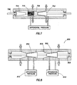
- test cell 7 Depicted in Figure 7 is a test cell in accordance with another exemplary embodiment of the present invention.
- the test cell comprises two conical plugs 702, 704 coupled to an axial positioning device 708.
- the first conical plug 702 and the second conical plug 704 may be at different tapered angles relative to the test cell wall 706.
- the axial positioning device 708 may be utilized to move the first conical plug 702 and the second conical plug 704 together or independently.
- a brush 710 may be used to clean the test cell as described above with respect to Figure 3 . This embodiment allows testing to be performed in either direction providing for investigation of different simulated fracture angles.
- Figure 8 depicts a test cell not in accordance with the present invention.
- a first conical plug 802 and a second conical plug 804 are coupled to an axial positioning device 808 and positioned so as to form different gap widths with the test cell wall 806.
- the axial positioning device 808 may be utilized to move the first conical plug 802 and the second conical plug 804 together or independently.
- a brush (not shown) may be used to clean the test cell 800 as described above with respect to Figure 3 . This arrangement provides for a simplified testing of rheology.
- two different differential pressures 810, 812 may be measured at one pump rate and the pump rate may be fixed to approximate the required shear rate.
- the shear thinning effect may be determined by comparing the differential pressure ratios measured at various pump rates.
- a third conical plug may be added to the configuration illustrated in Figure 8 .
- the third conical plug provides a third gap width, so that with three different constant pump rates the operating range of the measurements is increased to nine different shear rates.
- the capability to manipulate the gap widths and the flow rates makes it possible to selectively evaluate rheological behavior in a low shear rate regime where viscoplastics exhibit their "yield stress" behavior and a broad class of shear thinning fluids exhibit "Newtonian-like" behavior.
- rheological behavior may be evaluated in intermediate shear rate regime where details of the shear rate dependent viscosity function are revealed, and in the "upper Newtonian-like" regime.
- a broad range of shear rates enhances the characterization of flow behavior and the probability of defining the rheological model that best describes the rheology of any fluid that will not plug the gaps.
- This example enhances the evaluation of the yield stress parameter which represents the minimum shear stress required to initiate a shearing flow and reflects the transition between solid-like (elastic, Hookean, etc.) behavior and viscous-like (Newtonian, shear thinning, etc.) behavior.
- This parameter is important in defining the flow behavior of a class of systems that exhibit viscoplastic behavior, such as certain formulations of drilling muds.
- an increase in yield stress is followed by increases in apparent viscosities and annular pressure losses. It is also well known that an increase in annular pressure loss is followed by an increase in the Equivalent Circulating Density ("ECD").
- ECD Equivalent Circulating Density
- the ECD represents the effective hydraulic pressure exerted on the bottom of the wellbore by the combined effects of mud density and the total annular pressure loss resulting from hydraulic friction losses generated as the drilling fluid circulates through the annular channels in the drill string.
- the annular friction losses are highly sensitive to the value of the yield stress, with a lower yield stress indicating a lower total annular pressure loss. Consequently, a lower yield stress will reduce the contribution of the annular pressure loss to the ECD value.
- the plug may comprise a series of wedge shaped plugs and corresponding test cell walls.
- the characterization system 100 may perform in one or any combination of the modes of operation discussed above.
- the test cell 106 may be utilized in a combined mode of operation thereby providing rheology measurement of the treated fluid as well as fluid optimization.
Landscapes
- Engineering & Computer Science (AREA)
- Life Sciences & Earth Sciences (AREA)
- Chemical & Material Sciences (AREA)
- Physics & Mathematics (AREA)
- Mining & Mineral Resources (AREA)
- Geology (AREA)
- Health & Medical Sciences (AREA)
- General Health & Medical Sciences (AREA)
- Mechanical Engineering (AREA)
- Food Science & Technology (AREA)
- Analytical Chemistry (AREA)
- Biochemistry (AREA)
- Oil, Petroleum & Natural Gas (AREA)
- General Physics & Mathematics (AREA)
- Immunology (AREA)
- Pathology (AREA)
- Medicinal Chemistry (AREA)
- Environmental & Geological Engineering (AREA)
- Fluid Mechanics (AREA)
- General Chemical & Material Sciences (AREA)
- Chemical Kinetics & Catalysis (AREA)
- General Life Sciences & Earth Sciences (AREA)
- Geochemistry & Mineralogy (AREA)
- Investigating Strength Of Materials By Application Of Mechanical Stress (AREA)
- Sampling And Sample Adjustment (AREA)
- Testing Of Devices, Machine Parts, Or Other Structures Thereof (AREA)
Claims (18)
- Testzelle (106, 600, 800) zur Analyse eines Fluids, umfassend:einen ersten konischen Innenteil (306, 606),eine Axialpositionierungsvorrichtung (304, 708, 808), die entlang einer Achse der Testzelle positioniert ist,einen ersten konischen Stopfen (302, 602, 702, 802), der mit der Axialpositionierungsvorrichtung gekoppelt ist,wobei der erste konische Stopfen entlang der Achse der Testzelle in und aus dem ersten konischen Innenteil bewegbar ist,einen Fluideinlass (312) an einer ersten Stelle an der Testzelle,einen Fluidauslass (314) an einer zweiten Stelle an der Testzelle,wobei die Testzelle gekennzeichnet ist durch eine Bürste (316, 710), die mit der Axialpositionierungsvorrichtung gekoppelt ist.
- Testzelle nach Anspruch 1, die ferner eine Verdrängerpumpe (110, 112) aufweist, wobei die Verdrängerpumpe den Fluiddurchfluss durch die Testzelle regelt.
- Testzelle nach Anspruch 1, die ferner Folgendes aufweist:einen zweiten konischen Stopfen (704, 804), der mit der Axialpositionierungsvorrichtung gekoppelt ist,wobei der zweite konische Stopfen (704, 804) in und aus einem zweiten konischen Innenteil entlang der Achse der Testzelle bewegbar ist.
- Testzelle nach Anspruch 3, die ferner Folgendes aufweist:einen dritten konischen Stopfen, der mit der Axialpositionierungsvorrichtung gekoppelt ist,wobei der dritte konische Stopfen in und aus einem dritten konischen Innenteil entlang der Achse der Testzelle bewegbar ist.
- Testzelle nach Anspruch 4, wobei der erste konische Stopfen, der zweite konische Stopfen und der dritte konische Stopfen von der Axialpositionierungsvorrichtung jeweils unabhängig voneinander bewegt werden können.
- Testzelle nach Anspruch 1, die ferner Folgendes aufweist:ein Pilottestmischersystem (102) zum Zusetzen und Zumischen von Verstopfungsmaterialien zum Fluid undein mit dem Pilottestmischersystem gekoppeltes Verstopfungsmaterialentnahmesystem (104),wobei die Testzelle mit dem Verstopfungsmaterialentnahmesystem gekoppelt ist.
- Testzelle nach Anspruch 6, wobei der Pilottestmischer Folgendes aufweist:eine Mischbütte (202),eine Schlammförderpumpe (204), die abnehmbar mit der Mischbütte gekoppelt ist,eine Produktspeichereinheit (206, 208, 210), die abnehmbar mit der Mischbütte gekoppelt ist, undeine Verschlussvorrichtung (212), die abnehmbar mit der Mischbütte verbunden werden kann.
- Testzelle nach Anspruch 6, wobei das Verstopfungsmaterialentnahmesystem Folgendes aufweist:ein Filter (114) zum Entfernen von Verstopfungsmaterialien undeinen mit dem Filter gekoppelten Abfallbehälter (116).
- Verwendung einer Testzelle nach Anspruch 1 zur Ermittlung eines optimalen Leistungsbereichs für ein Fluid, die Folgendes aufweist:Herstellen eines Spalts zwischen einem ersten konischen Stopfen und dem ersten konischen Teil in der Testzelle,Durchströmenlassen des Fluids durch den Spalt,Ermitteln des Abdichtungswirkungsgrads des Fluids, während die Spaltbreite verändert wird, undIdentifizieren von Spaltbreiten eines optimalen Leistungsbereichs für das Fluid.
- Verwendung nach Anspruch 9, wobei der Abdichtungswirkungsgrad des Fluids auf der Basis von Faktoren, die aus der Gruppe bestehend aus Dichtungsrate und Gesamtfluidverlust in einer festen Zeitspanne gewählt werden, ermittelt wird.
- Verwendung nach Anspruch 9, wobei das Fluid ein Bohrfluid ist.
- Verwendung einer Testzelle nach Anspruch 1 zum Messen der Rheologie eines ersten Fluids, umfassend:Hindurchführen des ersten Fluids durch einen zwischen dem ersten konischen Stopfen und dem ersten konischen Teil der Testzelle gebildeten Spalt,Messen eines Druckabfalls am Spalt entlang,Verwenden des Druckabfallmesswerts zum Ermitteln einer Scherspannung,Messen des Durchflusses des ersten Fluids durch den Spalt,Verwenden des Durchflussmesswerts und der Strömungsgeometrie zum Ermitteln einer durchschnittlichen Schergeschwindigkeit,Vorhersagen von rheologischen Modellparametern des ersten Fluids mithilfe der Scherspannung und der durchschnittlichen Schergeschwindigkeit.
- Verwendung nach Anspruch 12, wobei die rheologischen Modellparameter ausgewählt werden aus der Gruppe bestehend aus: plastische Viskosität, Bingham-Modell-Fließgrenze und Herschel-Bulkley-Modellparameter.
- Verwendung nach Anspruch 12, die ferner Folgendes aufweist:Hindurchführen eines zweiten Fluids durch den zwischen dem ersten konischen Stopfen und dem ersten konischen Teil der Testzelle gebildeten Spalt,Messen eines Druckabfalls am Spalt entlang,Verwenden des Druckabfallmesswerts zum Ermitteln einer Scherspannung,Messen des Durchflusses des zweiten Fluids durch den Spalt,Verwenden des Durchflussmesswerts zum Ermitteln einer durchschnittlichen Schergeschwindigkeit,Vorhersagen eines rheologischen Modells des zweiten Fluids mithilfe der Scherspannung und der durchschnittlichen Schergeschwindigkeit undVergleichen des rheologischen Modells des ersten Fluids und des zweiten Fluids.
- Verwendung nach Anspruch 14, wobei das erste Fluid ein verstopfungsmaterialhaltiges Fluid ist und das zweite Fluid ein von Verstopfungsmaterialteilchen freies Fluid ist.
- Verwendung einer Testzelle nach Anspruch 1 zur Optimierung des Abdichtungswirkungsgrads, die Folgendes aufweist:Herstellen eines Spalts zwischen dem ersten konischen Stopfen und dem ersten konischen Teil in der Testzelle,wobei die Spaltbreite eine Bruchbreite simuliert,Durchströmenlassen eines ersten Fluids durch den Spalt,Ermitteln des Abdichtungswirkungsgrads des ersten Bohrfluids,Bewegen der Axialpositionierungsvorrichtung, um die Bürste zu bewegen, um den Spalt zu räumen,Durchströmenlassen eines zweiten Fluids durch den Spalt,Ermitteln des Abdichtungswirkungsgrads des zweiten Fluids undErmitteln, welches des ersten Fluids und des zweiten Fluids beim Abdichten des Spalts wirksamer ist.
- Verwendung nach Anspruch 16, wobei das Ermitteln des Abdichtungswirkungsgrads das Identifizieren des Volumens eines Fluids, das zum Abdichten des Spalts erforderlich ist, aufweist.
- Verwendung einer Testzelle nach Anspruch 1 zur Optimierung des Abdichtungswirkungsgrads, die Folgendes aufweist:Herstellen eines Spalts zwischen dem ersten konischen Stopfen und dem ersten konischen Teil in der Testzelle,wobei die Spaltbreite eine Bruchbreite simuliert,Durchströmenlassen eines ersten Fluids durch den Spalt,Ermitteln des Abdichtungswirkungsgrads des ersten Fluids,Durchströmenlassen eines zweiten Fluids durch den Spalt,Ermitteln des Abdichtungswirkungsgrads eines Gemisches aus dem ersten Fluid und dem zweiten Fluid,Ermitteln, ob das zweite Fluid den Abdichtungswirkungsgrad des ersten Fluids verbesserte.
Priority Applications (1)
| Application Number | Priority Date | Filing Date | Title |
|---|---|---|---|
| PL09765159T PL2352997T3 (pl) | 2008-12-05 | 2009-12-02 | Sposoby i systemy do charakteryzacji zatykania cząstki LCM i reologii w czasie rzeczywistym |
Applications Claiming Priority (2)
| Application Number | Priority Date | Filing Date | Title |
|---|---|---|---|
| US12/328,836 US8151633B2 (en) | 2008-12-05 | 2008-12-05 | Methods and systems for characterizing LCM particle plugging and rheology in real time |
| PCT/GB2009/002807 WO2010064009A1 (en) | 2008-12-05 | 2009-12-02 | Methods and systems for characterizing lcm particle plugging and rheology in real time |
Publications (2)
| Publication Number | Publication Date |
|---|---|
| EP2352997A1 EP2352997A1 (de) | 2011-08-10 |
| EP2352997B1 true EP2352997B1 (de) | 2014-07-09 |
Family
ID=41728024
Family Applications (1)
| Application Number | Title | Priority Date | Filing Date |
|---|---|---|---|
| EP09765159.0A Active EP2352997B1 (de) | 2008-12-05 | 2009-12-02 | Verfahren und systeme zur echtzeitcharakterisierung von lcm-partikelverstopfung und -rheologie |
Country Status (14)
| Country | Link |
|---|---|
| US (2) | US8151633B2 (de) |
| EP (1) | EP2352997B1 (de) |
| AU (1) | AU2009323867B2 (de) |
| BR (1) | BRPI0922751A2 (de) |
| CA (3) | CA2936908A1 (de) |
| DK (1) | DK2352997T3 (de) |
| EA (1) | EA026009B1 (de) |
| EC (1) | ECSP11011111A (de) |
| ES (1) | ES2500641T3 (de) |
| MX (1) | MX2011005762A (de) |
| MY (1) | MY161409A (de) |
| PL (1) | PL2352997T3 (de) |
| PT (1) | PT2352997E (de) |
| WO (1) | WO2010064009A1 (de) |
Families Citing this family (29)
| Publication number | Priority date | Publication date | Assignee | Title |
|---|---|---|---|---|
| US9863240B2 (en) * | 2004-03-11 | 2018-01-09 | M-I L.L.C. | Method and apparatus for drilling a probabilistic approach |
| US8530393B2 (en) | 2011-04-15 | 2013-09-10 | Halliburton Energy Services, Inc. | Methods to characterize fracture plugging efficiency for drilling fluids |
| US9134291B2 (en) | 2012-01-26 | 2015-09-15 | Halliburton Energy Services, Inc. | Systems, methods and devices for analyzing drilling fluid |
| US9188522B2 (en) * | 2012-05-10 | 2015-11-17 | Halliburton Energy Services, Inc. | Methods and systems for testing lost circulation materials |
| US10175385B2 (en) | 2012-05-23 | 2019-01-08 | Halliburton Energy Services, Inc. | Optimization visualization using normalized achievement variables |
| US9388333B2 (en) | 2012-07-11 | 2016-07-12 | Halliburton Energy Services, Inc. | Methods relating to designing wellbore strengthening fluids |
| US20140060175A1 (en) * | 2012-09-06 | 2014-03-06 | Nathan R. Hutchings | Dual friction loop fluid flow resistance measurement apparatus |
| US9714565B2 (en) * | 2012-12-31 | 2017-07-25 | M-I L.L.C. | Slot tester |
| US9206681B2 (en) | 2013-02-07 | 2015-12-08 | Superior Graphite Co. | Wellbore fluid testing assembly |
| US8935957B2 (en) * | 2013-03-13 | 2015-01-20 | Halliburton Energy Services, Inc. | Methods of designing a drilling fluid having suspendable loss circulation material |
| US9513272B2 (en) * | 2013-03-15 | 2016-12-06 | National Oilwell Varco, L.P. | Method and apparatus for measuring drilling fluid properties |
| CN103197036A (zh) * | 2013-04-01 | 2013-07-10 | 西南石油大学 | 一种循环钻井液井底条件模拟装置 |
| WO2016085469A1 (en) | 2014-11-25 | 2016-06-02 | Halliburton Energy Services, Inc. | Evaluating solid particle separation in wellbore fluids |
| US10612374B2 (en) * | 2015-06-10 | 2020-04-07 | Halliburton Energy Services, Inc. | Apparatus and methods to manage wellbore fluid properties |
| US11111742B2 (en) * | 2017-03-16 | 2021-09-07 | Saudi Arabian Oil Company | Apparatus for loss circulation material performance evaluation |
| US11268381B2 (en) * | 2017-03-16 | 2022-03-08 | Saudi Arabian Oil Company | Additive manufacturing of a vugular loss zone simulating test device |
| US10508978B2 (en) | 2017-11-03 | 2019-12-17 | Saudi Arabian Oil Company | Strain energy-based method and apparatus to determine the coefficient of resilience of lost circulation materials |
| CN110593788A (zh) * | 2018-05-24 | 2019-12-20 | 广东技术师范学院 | 一种智能钻井液监测系统 |
| CN108827830B (zh) * | 2018-06-15 | 2023-11-14 | 西南石油大学 | 一种高温高压钻井液流动性能测试装置及方法 |
| US20200110015A1 (en) | 2018-10-04 | 2020-04-09 | Saudi Arabian Oil Company | Vugular Loss Simulating Vug Tester for Screening and Evaluation of LCM Products |
| US20200158619A1 (en) * | 2018-11-21 | 2020-05-21 | Baker Hughes, A Ge Company, Llc | Fracture pressure transmission test apparatus with flowback module |
| US11078748B2 (en) | 2019-02-05 | 2021-08-03 | Saudi Arabian Oil Company | Lost circulation shapes |
| US11371301B2 (en) | 2019-02-05 | 2022-06-28 | Saudi Arabian Oil Company | Lost circulation shape deployment |
| CN110261284B (zh) * | 2019-07-26 | 2024-01-19 | 荆州市现代石油科技发展有限公司 | 一种水溶性暂堵剂封堵性能的实验装置及评价方法 |
| US11492858B2 (en) | 2019-10-01 | 2022-11-08 | Halliburton Energy Services, Inc. | Estimating three dimensional networks of plugs for drilling fluid additives |
| US11435274B2 (en) | 2020-06-04 | 2022-09-06 | Saudi Arabian Oil Company | Continuous mud rheology monitoring |
| US11352545B2 (en) | 2020-08-12 | 2022-06-07 | Saudi Arabian Oil Company | Lost circulation material for reservoir section |
| US11761274B2 (en) * | 2021-12-17 | 2023-09-19 | Halliburton Energy Services, Inc. | Test apparatus for measuring particle plugging of a simulated fracture |
| CN117052347B (zh) * | 2023-09-26 | 2024-03-26 | 西南石油大学 | 一种堵漏模拟实验装置及其实验方法 |
Family Cites Families (14)
| Publication number | Priority date | Publication date | Assignee | Title |
|---|---|---|---|---|
| US3016734A (en) * | 1957-02-23 | 1962-01-16 | Sucker Gmbh Geb | Viscosity sensing or measuring apparatus |
| CA992348A (en) * | 1974-03-22 | 1976-07-06 | Helen G. Tucker | Measurement of at least one of the fluid flow rate and viscous characteristics using laminar flow and viscous shear |
| US5086646A (en) * | 1989-09-12 | 1992-02-11 | Jamison Dale E | Apparatus and method for analyzing well fluid sag |
| GB2250601B (en) * | 1990-12-04 | 1994-04-06 | Schlumberger Services Petrol | Rheometer |
| US6638049B1 (en) * | 1997-06-13 | 2003-10-28 | Synventive Molding Solutions, Inc. | Apparatus and method for proportionally controlling fluid delivery to readily replaceable mold inserts |
| GB2346702B (en) * | 1999-02-15 | 2001-05-16 | Sofitech Nv | Dynamic sag monitor for drilling fluids |
| DE10003093C2 (de) * | 2000-01-25 | 2002-05-16 | Goltz Volker Freiherr Von | Vorrichtung zur Untersuchung von Eigenschaften der globalen Hämostasefunktion in Vollblut oder plättchenreichem Plasma |
| US6755079B1 (en) * | 2000-03-27 | 2004-06-29 | Halliburton Energy Services, Inc. | Method and apparatus for determining fluid viscosity |
| US7290441B2 (en) * | 2001-10-31 | 2007-11-06 | Rheosense, Inc. | Micro slit viscometer with monolithically integrated pressure sensors |
| US6584833B1 (en) * | 2002-05-30 | 2003-07-01 | Halliburton Energy Services, Inc. | Apparatus and method for analyzing well fluid sag |
| US6931916B2 (en) * | 2003-06-25 | 2005-08-23 | M-I L.L.C. | Viscometer sag test shoe |
| US20050269085A1 (en) * | 2004-06-03 | 2005-12-08 | Cowan Kenneth M | Method for sealing lost circulation zones |
| JP2006241208A (ja) * | 2005-03-01 | 2006-09-14 | Fuji Photo Film Co Ltd | ドープの評価方法及び溶液製膜方法 |
| US8024962B2 (en) * | 2008-07-28 | 2011-09-27 | Halliburton Energy Services Inc. | Flow-through apparatus for testing particle laden fluids and methods of making and using same |
-
2008
- 2008-12-05 US US12/328,836 patent/US8151633B2/en active Active
-
2009
- 2009-12-02 AU AU2009323867A patent/AU2009323867B2/en active Active
- 2009-12-02 EP EP09765159.0A patent/EP2352997B1/de active Active
- 2009-12-02 PL PL09765159T patent/PL2352997T3/pl unknown
- 2009-12-02 DK DK09765159.0T patent/DK2352997T3/da active
- 2009-12-02 CA CA2936908A patent/CA2936908A1/en not_active Abandoned
- 2009-12-02 EA EA201170763A patent/EA026009B1/ru not_active IP Right Cessation
- 2009-12-02 MX MX2011005762A patent/MX2011005762A/es active IP Right Grant
- 2009-12-02 CA CA2806479A patent/CA2806479C/en not_active Expired - Fee Related
- 2009-12-02 BR BRPI0922751A patent/BRPI0922751A2/pt not_active Application Discontinuation
- 2009-12-02 CA CA2744967A patent/CA2744967C/en not_active Expired - Fee Related
- 2009-12-02 WO PCT/GB2009/002807 patent/WO2010064009A1/en not_active Ceased
- 2009-12-02 MY MYPI2011002535A patent/MY161409A/en unknown
- 2009-12-02 ES ES09765159.0T patent/ES2500641T3/es active Active
- 2009-12-02 PT PT97651590T patent/PT2352997E/pt unknown
-
2011
- 2011-06-06 EC EC2011011111A patent/ECSP11011111A/es unknown
-
2012
- 2012-02-23 US US13/403,749 patent/US20120152000A1/en not_active Abandoned
Also Published As
| Publication number | Publication date |
|---|---|
| EP2352997A1 (de) | 2011-08-10 |
| WO2010064009A1 (en) | 2010-06-10 |
| ES2500641T3 (es) | 2014-09-30 |
| PL2352997T3 (pl) | 2015-01-30 |
| CA2806479A1 (en) | 2010-06-10 |
| DK2352997T3 (da) | 2014-09-29 |
| CA2744967C (en) | 2015-01-27 |
| US20100139387A1 (en) | 2010-06-10 |
| EA201170763A1 (ru) | 2011-12-30 |
| AU2009323867B2 (en) | 2012-05-31 |
| US20120152000A1 (en) | 2012-06-21 |
| EA026009B1 (ru) | 2017-02-28 |
| CA2744967A1 (en) | 2010-06-10 |
| CA2806479C (en) | 2016-09-20 |
| CA2936908A1 (en) | 2010-06-10 |
| MX2011005762A (es) | 2011-06-28 |
| PT2352997E (pt) | 2014-09-11 |
| ECSP11011111A (es) | 2011-09-30 |
| MY161409A (en) | 2017-04-14 |
| AU2009323867A1 (en) | 2010-06-10 |
| BRPI0922751A2 (pt) | 2016-01-05 |
| US8151633B2 (en) | 2012-04-10 |
Similar Documents
| Publication | Publication Date | Title |
|---|---|---|
| CA2806479C (en) | Methods and systems for characterizing lcm particle plugging and rheology in real time | |
| Hussaini et al. | Experimental study of drilled cuttings transport using common drilling muds | |
| Vajargah et al. | Automated fluid rheology and ECD management | |
| WO2008118953A1 (en) | High pressure fracture tester | |
| Yu et al. | An experimental study of hole cleaning under simulated downhole conditions | |
| Bannister | Rheological evaluation of cement slurries: Methods and models | |
| Shad et al. | Dynamic analysis of mud loss during overbalanced drilling operation: An experimental study | |
| US7325607B2 (en) | Methods and systems for using high-yielding non-Newtonian fluids for severe lost circulation prevention | |
| Rommetveit et al. | HPHT Well Control; An Integrated Approach | |
| Adjei et al. | Evaluation and remediation techniques for barite sagging: A review | |
| AU2012202360B2 (en) | Methods and systems for characterizing LCM particle plugging and rheology in real time | |
| US7499846B2 (en) | Methods for using high-yielding non-Newtonian fluids for severe lost circulation prevention | |
| Ezeakacha et al. | A new approach to characterize dynamic drilling fluids invasion profiles in application to near-wellbore strengthening effect | |
| Zamora | Mechanisms, measurement and mitigation of barite sag | |
| US11906688B2 (en) | Using electrical signal as a measure of water wettability for direct emulsion fluids | |
| Ravi et al. | Improve primary cementing by continuous monitoring of circulatable hole | |
| Bahrami et al. | Factors Affecting Cement Quality of Intermediate Casing in the South Pars Gas Field: A 24-Well Case Study | |
| Van Der Zwaag et al. | Dynamic filtration: Seepage losses on tyrihans | |
| Kulkarni et al. | Modeling real-time sag in the wellbore | |
| Griffith et al. | Monitoring circulatable hole with real-time correction: case histories | |
| Amiri et al. | Effect of Shearing on Rheological Properties of Oil-Based Drilling Fluid Premixes | |
| Sairam et al. | A Combined Mixer Design With Helical Blades to Probe Rheology of Complex Oilfield Slurries and Pastes | |
| Shah et al. | Tests confirm operational status of a large-slot flow apparatus for characterizing fracturing fluids | |
| WO2023149814A1 (en) | Method for measuring proppant bridging | |
| Shariff et al. | An Experimental Study of Hole Cleaning Under Simulated Downhole Conditions |
Legal Events
| Date | Code | Title | Description |
|---|---|---|---|
| PUAI | Public reference made under article 153(3) epc to a published international application that has entered the european phase |
Free format text: ORIGINAL CODE: 0009012 |
|
| 17P | Request for examination filed |
Effective date: 20110606 |
|
| AK | Designated contracting states |
Kind code of ref document: A1 Designated state(s): AT BE BG CH CY CZ DE DK EE ES FI FR GB GR HR HU IE IS IT LI LT LU LV MC MK MT NL NO PL PT RO SE SI SK SM TR |
|
| DAX | Request for extension of the european patent (deleted) | ||
| 17Q | First examination report despatched |
Effective date: 20120307 |
|
| GRAP | Despatch of communication of intention to grant a patent |
Free format text: ORIGINAL CODE: EPIDOSNIGR1 |
|
| INTG | Intention to grant announced |
Effective date: 20140210 |
|
| GRAS | Grant fee paid |
Free format text: ORIGINAL CODE: EPIDOSNIGR3 |
|
| GRAA | (expected) grant |
Free format text: ORIGINAL CODE: 0009210 |
|
| AK | Designated contracting states |
Kind code of ref document: B1 Designated state(s): AT BE BG CH CY CZ DE DK EE ES FI FR GB GR HR HU IE IS IT LI LT LU LV MC MK MT NL NO PL PT RO SE SI SK SM TR |
|
| REG | Reference to a national code |
Ref country code: GB Ref legal event code: FG4D |
|
| REG | Reference to a national code |
Ref country code: CH Ref legal event code: EP Ref country code: AT Ref legal event code: REF Ref document number: 676748 Country of ref document: AT Kind code of ref document: T Effective date: 20140715 |
|
| REG | Reference to a national code |
Ref country code: IE Ref legal event code: FG4D |
|
| REG | Reference to a national code |
Ref country code: DE Ref legal event code: R096 Ref document number: 602009025226 Country of ref document: DE Effective date: 20140821 |
|
| REG | Reference to a national code |
Ref country code: PT Ref legal event code: SC4A Free format text: AVAILABILITY OF NATIONAL TRANSLATION Effective date: 20140903 |
|
| REG | Reference to a national code |
Ref country code: DK Ref legal event code: T3 Effective date: 20140922 |
|
| REG | Reference to a national code |
Ref country code: ES Ref legal event code: FG2A Ref document number: 2500641 Country of ref document: ES Kind code of ref document: T3 Effective date: 20140930 |
|
| REG | Reference to a national code |
Ref country code: NL Ref legal event code: T3 |
|
| REG | Reference to a national code |
Ref country code: AT Ref legal event code: MK05 Ref document number: 676748 Country of ref document: AT Kind code of ref document: T Effective date: 20140709 |
|
| REG | Reference to a national code |
Ref country code: NO Ref legal event code: T2 Effective date: 20140709 |
|
| REG | Reference to a national code |
Ref country code: LT Ref legal event code: MG4D |
|
| PG25 | Lapsed in a contracting state [announced via postgrant information from national office to epo] |
Ref country code: GR Free format text: LAPSE BECAUSE OF FAILURE TO SUBMIT A TRANSLATION OF THE DESCRIPTION OR TO PAY THE FEE WITHIN THE PRESCRIBED TIME-LIMIT Effective date: 20141010 Ref country code: FI Free format text: LAPSE BECAUSE OF FAILURE TO SUBMIT A TRANSLATION OF THE DESCRIPTION OR TO PAY THE FEE WITHIN THE PRESCRIBED TIME-LIMIT Effective date: 20140709 Ref country code: SE Free format text: LAPSE BECAUSE OF FAILURE TO SUBMIT A TRANSLATION OF THE DESCRIPTION OR TO PAY THE FEE WITHIN THE PRESCRIBED TIME-LIMIT Effective date: 20140709 Ref country code: LT Free format text: LAPSE BECAUSE OF FAILURE TO SUBMIT A TRANSLATION OF THE DESCRIPTION OR TO PAY THE FEE WITHIN THE PRESCRIBED TIME-LIMIT Effective date: 20140709 Ref country code: BG Free format text: LAPSE BECAUSE OF FAILURE TO SUBMIT A TRANSLATION OF THE DESCRIPTION OR TO PAY THE FEE WITHIN THE PRESCRIBED TIME-LIMIT Effective date: 20141009 |
|
| REG | Reference to a national code |
Ref country code: PL Ref legal event code: T3 |
|
| PG25 | Lapsed in a contracting state [announced via postgrant information from national office to epo] |
Ref country code: IS Free format text: LAPSE BECAUSE OF FAILURE TO SUBMIT A TRANSLATION OF THE DESCRIPTION OR TO PAY THE FEE WITHIN THE PRESCRIBED TIME-LIMIT Effective date: 20141109 Ref country code: AT Free format text: LAPSE BECAUSE OF FAILURE TO SUBMIT A TRANSLATION OF THE DESCRIPTION OR TO PAY THE FEE WITHIN THE PRESCRIBED TIME-LIMIT Effective date: 20140709 Ref country code: LV Free format text: LAPSE BECAUSE OF FAILURE TO SUBMIT A TRANSLATION OF THE DESCRIPTION OR TO PAY THE FEE WITHIN THE PRESCRIBED TIME-LIMIT Effective date: 20140709 Ref country code: HR Free format text: LAPSE BECAUSE OF FAILURE TO SUBMIT A TRANSLATION OF THE DESCRIPTION OR TO PAY THE FEE WITHIN THE PRESCRIBED TIME-LIMIT Effective date: 20140709 Ref country code: CY Free format text: LAPSE BECAUSE OF FAILURE TO SUBMIT A TRANSLATION OF THE DESCRIPTION OR TO PAY THE FEE WITHIN THE PRESCRIBED TIME-LIMIT Effective date: 20140709 |
|
| REG | Reference to a national code |
Ref country code: DE Ref legal event code: R097 Ref document number: 602009025226 Country of ref document: DE |
|
| PG25 | Lapsed in a contracting state [announced via postgrant information from national office to epo] |
Ref country code: CZ Free format text: LAPSE BECAUSE OF FAILURE TO SUBMIT A TRANSLATION OF THE DESCRIPTION OR TO PAY THE FEE WITHIN THE PRESCRIBED TIME-LIMIT Effective date: 20140709 Ref country code: SK Free format text: LAPSE BECAUSE OF FAILURE TO SUBMIT A TRANSLATION OF THE DESCRIPTION OR TO PAY THE FEE WITHIN THE PRESCRIBED TIME-LIMIT Effective date: 20140709 Ref country code: EE Free format text: LAPSE BECAUSE OF FAILURE TO SUBMIT A TRANSLATION OF THE DESCRIPTION OR TO PAY THE FEE WITHIN THE PRESCRIBED TIME-LIMIT Effective date: 20140709 Ref country code: RO Free format text: LAPSE BECAUSE OF FAILURE TO SUBMIT A TRANSLATION OF THE DESCRIPTION OR TO PAY THE FEE WITHIN THE PRESCRIBED TIME-LIMIT Effective date: 20140709 |
|
| PLBE | No opposition filed within time limit |
Free format text: ORIGINAL CODE: 0009261 |
|
| STAA | Information on the status of an ep patent application or granted ep patent |
Free format text: STATUS: NO OPPOSITION FILED WITHIN TIME LIMIT |
|
| 26N | No opposition filed |
Effective date: 20150410 |
|
| PG25 | Lapsed in a contracting state [announced via postgrant information from national office to epo] |
Ref country code: LU Free format text: LAPSE BECAUSE OF FAILURE TO SUBMIT A TRANSLATION OF THE DESCRIPTION OR TO PAY THE FEE WITHIN THE PRESCRIBED TIME-LIMIT Effective date: 20141202 |
|
| REG | Reference to a national code |
Ref country code: CH Ref legal event code: PL |
|
| REG | Reference to a national code |
Ref country code: IE Ref legal event code: MM4A |
|
| PG25 | Lapsed in a contracting state [announced via postgrant information from national office to epo] |
Ref country code: LI Free format text: LAPSE BECAUSE OF NON-PAYMENT OF DUE FEES Effective date: 20141231 Ref country code: CH Free format text: LAPSE BECAUSE OF NON-PAYMENT OF DUE FEES Effective date: 20141231 Ref country code: IE Free format text: LAPSE BECAUSE OF NON-PAYMENT OF DUE FEES Effective date: 20141202 |
|
| REG | Reference to a national code |
Ref country code: FR Ref legal event code: PLFP Year of fee payment: 7 |
|
| PG25 | Lapsed in a contracting state [announced via postgrant information from national office to epo] |
Ref country code: SI Free format text: LAPSE BECAUSE OF FAILURE TO SUBMIT A TRANSLATION OF THE DESCRIPTION OR TO PAY THE FEE WITHIN THE PRESCRIBED TIME-LIMIT Effective date: 20140709 |
|
| PG25 | Lapsed in a contracting state [announced via postgrant information from national office to epo] |
Ref country code: SM Free format text: LAPSE BECAUSE OF FAILURE TO SUBMIT A TRANSLATION OF THE DESCRIPTION OR TO PAY THE FEE WITHIN THE PRESCRIBED TIME-LIMIT Effective date: 20140709 |
|
| PG25 | Lapsed in a contracting state [announced via postgrant information from national office to epo] |
Ref country code: MC Free format text: LAPSE BECAUSE OF FAILURE TO SUBMIT A TRANSLATION OF THE DESCRIPTION OR TO PAY THE FEE WITHIN THE PRESCRIBED TIME-LIMIT Effective date: 20140709 |
|
| PG25 | Lapsed in a contracting state [announced via postgrant information from national office to epo] |
Ref country code: MT Free format text: LAPSE BECAUSE OF FAILURE TO SUBMIT A TRANSLATION OF THE DESCRIPTION OR TO PAY THE FEE WITHIN THE PRESCRIBED TIME-LIMIT Effective date: 20140709 Ref country code: HU Free format text: LAPSE BECAUSE OF FAILURE TO SUBMIT A TRANSLATION OF THE DESCRIPTION OR TO PAY THE FEE WITHIN THE PRESCRIBED TIME-LIMIT; INVALID AB INITIO Effective date: 20091202 |
|
| REG | Reference to a national code |
Ref country code: FR Ref legal event code: PLFP Year of fee payment: 8 |
|
| PGFP | Annual fee paid to national office [announced via postgrant information from national office to epo] |
Ref country code: DE Payment date: 20161027 Year of fee payment: 8 Ref country code: FR Payment date: 20161021 Year of fee payment: 8 Ref country code: NL Payment date: 20161207 Year of fee payment: 8 Ref country code: DK Payment date: 20161124 Year of fee payment: 8 |
|
| PGFP | Annual fee paid to national office [announced via postgrant information from national office to epo] |
Ref country code: BE Payment date: 20161215 Year of fee payment: 8 Ref country code: PT Payment date: 20161125 Year of fee payment: 8 Ref country code: PL Payment date: 20161006 Year of fee payment: 8 Ref country code: ES Payment date: 20161215 Year of fee payment: 8 |
|
| PGFP | Annual fee paid to national office [announced via postgrant information from national office to epo] |
Ref country code: TR Payment date: 20161116 Year of fee payment: 8 |
|
| PGFP | Annual fee paid to national office [announced via postgrant information from national office to epo] |
Ref country code: IT Payment date: 20161222 Year of fee payment: 8 |
|
| PG25 | Lapsed in a contracting state [announced via postgrant information from national office to epo] |
Ref country code: MK Free format text: LAPSE BECAUSE OF FAILURE TO SUBMIT A TRANSLATION OF THE DESCRIPTION OR TO PAY THE FEE WITHIN THE PRESCRIBED TIME-LIMIT Effective date: 20140709 |
|
| REG | Reference to a national code |
Ref country code: DE Ref legal event code: R119 Ref document number: 602009025226 Country of ref document: DE |
|
| REG | Reference to a national code |
Ref country code: DK Ref legal event code: EBP Effective date: 20171231 |
|
| PG25 | Lapsed in a contracting state [announced via postgrant information from national office to epo] |
Ref country code: PT Free format text: LAPSE BECAUSE OF NON-PAYMENT OF DUE FEES Effective date: 20180604 |
|
| REG | Reference to a national code |
Ref country code: NL Ref legal event code: MM Effective date: 20180101 |
|
| PG25 | Lapsed in a contracting state [announced via postgrant information from national office to epo] |
Ref country code: NL Free format text: LAPSE BECAUSE OF NON-PAYMENT OF DUE FEES Effective date: 20180101 |
|
| REG | Reference to a national code |
Ref country code: FR Ref legal event code: ST Effective date: 20180831 |
|
| REG | Reference to a national code |
Ref country code: BE Ref legal event code: MM Effective date: 20171231 |
|
| PG25 | Lapsed in a contracting state [announced via postgrant information from national office to epo] |
Ref country code: DE Free format text: LAPSE BECAUSE OF NON-PAYMENT OF DUE FEES Effective date: 20180703 Ref country code: FR Free format text: LAPSE BECAUSE OF NON-PAYMENT OF DUE FEES Effective date: 20180102 Ref country code: IT Free format text: LAPSE BECAUSE OF NON-PAYMENT OF DUE FEES Effective date: 20171202 |
|
| PG25 | Lapsed in a contracting state [announced via postgrant information from national office to epo] |
Ref country code: BE Free format text: LAPSE BECAUSE OF NON-PAYMENT OF DUE FEES Effective date: 20171231 |
|
| PG25 | Lapsed in a contracting state [announced via postgrant information from national office to epo] |
Ref country code: DK Free format text: LAPSE BECAUSE OF NON-PAYMENT OF DUE FEES Effective date: 20171231 |
|
| PG25 | Lapsed in a contracting state [announced via postgrant information from national office to epo] |
Ref country code: PL Free format text: LAPSE BECAUSE OF NON-PAYMENT OF DUE FEES Effective date: 20171202 |
|
| REG | Reference to a national code |
Ref country code: ES Ref legal event code: FD2A Effective date: 20190702 |
|
| PG25 | Lapsed in a contracting state [announced via postgrant information from national office to epo] |
Ref country code: ES Free format text: LAPSE BECAUSE OF NON-PAYMENT OF DUE FEES Effective date: 20171203 |
|
| PGFP | Annual fee paid to national office [announced via postgrant information from national office to epo] |
Ref country code: NO Payment date: 20191125 Year of fee payment: 11 |
|
| REG | Reference to a national code |
Ref country code: NO Ref legal event code: MMEP |
|
| PG25 | Lapsed in a contracting state [announced via postgrant information from national office to epo] |
Ref country code: NO Free format text: LAPSE BECAUSE OF NON-PAYMENT OF DUE FEES Effective date: 20201231 |
|
| PG25 | Lapsed in a contracting state [announced via postgrant information from national office to epo] |
Ref country code: TR Free format text: LAPSE BECAUSE OF NON-PAYMENT OF DUE FEES Effective date: 20171202 |
|
| PGFP | Annual fee paid to national office [announced via postgrant information from national office to epo] |
Ref country code: GB Payment date: 20251103 Year of fee payment: 17 |