EP2352966B1 - Gimbaled system with optical coudé path and method transferring data - Google Patents
Gimbaled system with optical coudé path and method transferring data Download PDFInfo
- Publication number
- EP2352966B1 EP2352966B1 EP09832221.7A EP09832221A EP2352966B1 EP 2352966 B1 EP2352966 B1 EP 2352966B1 EP 09832221 A EP09832221 A EP 09832221A EP 2352966 B1 EP2352966 B1 EP 2352966B1
- Authority
- EP
- European Patent Office
- Prior art keywords
- gimbal
- laser
- path
- communication
- data
- Prior art date
- Legal status (The legal status is an assumption and is not a legal conclusion. Google has not performed a legal analysis and makes no representation as to the accuracy of the status listed.)
- Active
Links
Images
Classifications
-
- G—PHYSICS
- G01—MEASURING; TESTING
- G01C—MEASURING DISTANCES, LEVELS OR BEARINGS; SURVEYING; NAVIGATION; GYROSCOPIC INSTRUMENTS; PHOTOGRAMMETRY OR VIDEOGRAMMETRY
- G01C21/00—Navigation; Navigational instruments not provided for in groups G01C1/00 - G01C19/00
- G01C21/26—Navigation; Navigational instruments not provided for in groups G01C1/00 - G01C19/00 specially adapted for navigation in a road network
- G01C21/28—Navigation; Navigational instruments not provided for in groups G01C1/00 - G01C19/00 specially adapted for navigation in a road network with correlation of data from several navigational instruments
-
- G—PHYSICS
- G01—MEASURING; TESTING
- G01S—RADIO DIRECTION-FINDING; RADIO NAVIGATION; DETERMINING DISTANCE OR VELOCITY BY USE OF RADIO WAVES; LOCATING OR PRESENCE-DETECTING BY USE OF THE REFLECTION OR RERADIATION OF RADIO WAVES; ANALOGOUS ARRANGEMENTS USING OTHER WAVES
- G01S17/00—Systems using the reflection or reradiation of electromagnetic waves other than radio waves, e.g. lidar systems
- G01S17/86—Combinations of lidar systems with systems other than lidar, radar or sonar, e.g. with direction finders
-
- G—PHYSICS
- G01—MEASURING; TESTING
- G01S—RADIO DIRECTION-FINDING; RADIO NAVIGATION; DETERMINING DISTANCE OR VELOCITY BY USE OF RADIO WAVES; LOCATING OR PRESENCE-DETECTING BY USE OF THE REFLECTION OR RERADIATION OF RADIO WAVES; ANALOGOUS ARRANGEMENTS USING OTHER WAVES
- G01S7/00—Details of systems according to groups G01S13/00, G01S15/00, G01S17/00
- G01S7/48—Details of systems according to groups G01S13/00, G01S15/00, G01S17/00 of systems according to group G01S17/00
- G01S7/481—Constructional features, e.g. arrangements of optical elements
- G01S7/4811—Constructional features, e.g. arrangements of optical elements common to transmitter and receiver
- G01S7/4812—Constructional features, e.g. arrangements of optical elements common to transmitter and receiver transmitted and received beams following a coaxial path
-
- G—PHYSICS
- G01—MEASURING; TESTING
- G01S—RADIO DIRECTION-FINDING; RADIO NAVIGATION; DETERMINING DISTANCE OR VELOCITY BY USE OF RADIO WAVES; LOCATING OR PRESENCE-DETECTING BY USE OF THE REFLECTION OR RERADIATION OF RADIO WAVES; ANALOGOUS ARRANGEMENTS USING OTHER WAVES
- G01S7/00—Details of systems according to groups G01S13/00, G01S15/00, G01S17/00
- G01S7/48—Details of systems according to groups G01S13/00, G01S15/00, G01S17/00 of systems according to group G01S17/00
- G01S7/481—Constructional features, e.g. arrangements of optical elements
- G01S7/4811—Constructional features, e.g. arrangements of optical elements common to transmitter and receiver
- G01S7/4813—Housing arrangements
Definitions
- Some embodiments pertain to gimbaled systems. Some embodiments pertain to gimbaled imaging systems. Some embodiments pertain to gimbaled laser imaging systems that use Laser Detection and Ranging (LADAR).
- LADAR Laser Detection and Ranging
- Some embodiments pertain to gimbaled systems. Some embodiments pertain to gimbaled imaging systems. Some embodiments pertain to gimbaled laser imaging systems that use Laser Detection and Ranging (LADAR).
- LADAR Laser Detection and Ranging
- US6288381B1 describes an alignment and stabilization system that automatically aligns and stabilizes off-gimbal electro-optical passive and active sensors.
- US2003174315A1 describes a multi-emitter boresight reference source comprising first and second mechanisms for transmitting respective first and second portions of electromagnetic energy and a third mechanism for combining the first and second portions.
- gimbaled systems One issue with gimbaled systems is the transfer of data across the gimbal axes. Many conventional gimbaled systems use electrical slip rings or harnesses to transfer data cross the gimbal axes. For large amounts of data, electrical slip rings become more complex and may be less reliable. Harnesses become larger and induce undesired torque on the gimbaled system.
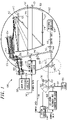
- FIG. 1 illustrates a gimbaled system with an optical coudé path in accordance with some embodiments.
- Gimbaled system 100 includes a plurality of on-gimbal elements within gimbaled payload 102 and a plurality of off-gimbal elements located external to gimbaled payload 102.
- Gimbaled system 100 also includes optical coudé path 101 to provide a data communication path between some of the elements located on gimbaled payload 102 and some of the elements located off gimbaled payload 102.
- gimbaled system 100 includes off-gimbal communication laser 108 to transmit information, such as modulated control data 110, via coudé path 101.
- Gimbaled system 100 may also include on-gimbal communication detector 112 to detect data, such as modulated control data 110, received across coudé path 101.
- Optical coudé path 101 allows large amounts of data to be transferred across gimbal axes without high data rate multi-channel electrical slip rings or torque inducing harnesses.
- optical coudé path 101 includes at least two mirrors 103 to provide a communication path through an azimuth axis and an elevation axis of gimbaled payload 102.
- a bi-directional communication path may be provided, although the scope of the embodiments is not limited in this respect. These embodiments are discussed in more detail below.
- off-gimbal communication laser 108 may generate an auto-alignment beam to align transmit path 124 and receive path 126 of gimbaled system 100.
- the auto-alignment beam may be modulated to communicate control data 110 via coudé path 101.
- gimbaled system 100 may also include alignment detector 130 to detect wavelengths of the auto-alignment beam to indicate when transmit path 124 and receive path 126 are aligned.
- off-gimbal communication laser 108 serves as both a data communication laser and an auto-alignment laser.
- a separate auto-alignment laser may be used, which may be provided off gimbal or on gimbal.
- auto alignment with ten micro-radians may be achieved to correct for cross gimbal errors, although the scope of the embodiments is not limited in this respect.
- gimbaled system 100 may also include on-gimbal communication laser 114 to transmit data, such as modulated camera data 116, via coudé path 101.
- Gimbaled system 100 may also include off-gimbal communication detector 118 to detect data, such as modulated camera data 116, received via coudé path 101.
- These embodiments may allow large amounts of video data to be transferred off gimbal via optical coudé path 101.
- data transfer rates of up to 2 Giga-bits-per-second (Gbps) or greater may be achieved.
- Gbps Giga-bits-per-second
- a bi-directional communication of data may be achieved to allow command data 110 to be transferred on gimbal.
- on-gimbal communication detector 112 and off-gimbal communication detector 118 may include circuitry to detect and demodulate the received laser wavelengths.
- gimbaled system 100 may include designator laser 120 configured to illuminate (i.e., designate) a target region by transmitting laser wavelengths 121 along transmit path 124.
- the target region may be on the ground (e.g., to designate a building or vehicle) or on a body of water (e.g., designate a watercraft or vessel).
- gimbaled system 100 may be a laser designation system, although the scope of the embodiments is not limited in this respect.
- designator laser 120 may be provided off-gimbal 102 and the laser wavelengths generated by designator laser 120 may be provided via coudé path 101.
- gimbaled system 100 may also include focal plane array (FPA) 128 to convert return laser wavelengths 127 received through receive path 126 to electrical signals.
- FPA focal plane array
- gimbaled system 100 may also include on-gimbal processing circuitry 136 to generate data such as camera data 116 from the electrical signals for use in modulation of laser wavelengths generated by on-gimbal communication laser 114 for transmission via optical coudé path 101 to the off-gimbal communication detector 118.
- Laser wavelengths 127 received through receive path 126 may be received through lens 156 of gimbaled payload 102.
- designator laser 120 may be configured as a Laser Detection and Ranging (LADAR) laser to transmit LADAR signals, which may include pulsed laser wavelengths for ranging and imaging.
- LADAR Laser Detection and Ranging
- camera data 116 may comprise LADAR data.
- the LADAR signals may comprise pulsed laser wavelengths to simultaneously obtain target range information and target images.
- camera data 116 may include video imaging and/or still photographic data from the target region.
- gimbaled system 100 may be a laser imaging system, although the scope of the embodiments is not limited in this respect.
- control data 110 may include command signals ton control one or more functional elements located on gimbaled payload 102.
- control data 110 may be used to switch between one of a plurality of on-gimbal cameras provided on gimbaled payload 102.
- Control data 110 may also be used to control movement of gimbaled payload 102 within its pod.
- control data 110 may be used to control movable optical elements located on gimbaled payload 102.
- Gimbaled system 100 may also include system controller 138 located off gimbal to provide control data 110 to off-gimbal communication laser 108 for modulation and transmission via coudé path 101.
- Gimbaled system 100 may also include on-gimbal controller 134 to receive detected control data 110 from on-gimbal communication detector 112.
- System controller 138 may also be configured to receive detected camera data 116 from off-gimbal communication detector 118, although detected camera data 116 may be provided to other system elements not separately illustrated.
- on-gimbal controller 134 may be configured to provide data, such as navigational data that may be obtained by navigational elements of gimbaled payload 102, to on-gimbal communication laser 114 for transmission via coudé path 101, although the scope of the embodiments is not limited in this respect.
- data such as navigational data that may be obtained by navigational elements of gimbaled payload 102
- on-gimbal communication laser 114 for transmission via coudé path 101, although the scope of the embodiments is not limited in this respect.
- the signal path between on-gimbal controller 134 and on-gimbal communication laser 114 is not separately illustrated.
- On-gimbal controller 134 may also be configured to receive an indication from alignment detector 130 when alignment is detected and may provide the indication via coudé path 101, although the scope of the embodiments is not limited in this respect. For clarity, the signal path between on-gimbal controller 134 and alignment detector 130 is not separately illustrated.
- gimbaled system 100 may include various optical elements to combine and/or separate the various laser wavelengths for performing the functions described herein.
- gimbaled system 100 may include beam combiner 140 located off gimbal to combine laser wavelengths generated by off-gimbal communication laser 108 with laser wavelengths generated by designator laser 120 (or in some embodiments the LADAR laser) for subsequent transmission via coudé path 101.
- Gimbaled system 100 may also include beam splitter 142 located off gimbal to direct laser wavelengths generated by on-gimbal communication laser 114 carrying camera data 116 received via coudé path 101 to off-gimbal communication detector 118.
- beam splitter 142 located off gimbal to direct laser wavelengths generated by on-gimbal communication laser 114 carrying camera data 116 received via coudé path 101 to off-gimbal communication detector 118.
- Gimbaled system 100 may also include beam splitter 144 located on gimbal to direct laser wavelengths generated by off-gimbal communication laser 108 carrying control data 110 received via coudé path 101 to on-gimbal communication detector 112.
- Beam splitter 144 may be configured to direct a portion of the laser wavelengths carrying control data 110 to on-gimbal communication detector 112 and to direct another portion of the laser wavelengths that comprise the auto-alignment beam to alignment detector 130.
- the laser wavelengths carrying the control data 110 are also used as the auto alignment beam. Beam splitter 144 accordingly directs a portion of the energy to on-gimbal communication detector 112 and a portion of the energy for direction to alignment detector 130.
- Gimbaled system 100 may also include beam combiner 148 located on gimbal to provide laser wavelengths generated by on-gimbal communication laser 114 for subsequent transmission via coudé path 101.
- beam combiner 148 may be configured to allow passage of laser wavelengths generated by LADAR laser 120 received via coudé path 101.
- Gimbaled system 100 may also include beam splitter 146 located on gimbal to direct wavelengths of the auto-alignment beam generated by off gimbal communication laser 108 to alignment detector 130.
- Beam splitter 146 may also be configured to allow wavelengths generated by on-gimbal communication laser 114 to pass.
- beam splitters 142, 144, 146 and beam combiners 140 and 148 may include reflective and/or transmissive elements with optical coatings selected to perform the functions described herein.
- optical coatings may be selected to allow one or more laser wavelengths to be reflected and to allow one or more other laser wavelengths to pass through.
- the optical coatings may be selected to allow a portion of the energy of one or more laser wavelengths to be reflected and to allow another portion of the energy of these laser wavelengths to pass.
- on-gimbal communication laser 114 and off-gimbal communication laser 108 transmit modulated data at different laser wavelengths.
- beam splitters 142, 144, 146 and beam combiners 140 and 148 may be appropriately configured based on the different laser wavelengths on-gimbal communication laser 114 and off-gimbal communication laser 108.
- beam splitters 142, 144, and 146 may be configured to either pass or reflect substantially all of a predetermined laser wavelength so that little or no undesired energy would go where it is not intended.
- Beam combiner 140 may be configured to reflect substantially all energy of the wavelengths generated by off gimbal communication laser 108 and transmit the wavelengths generated by LADAR laser 120.
- Beam splitter 144 may be configured to transmit the wavelengths generated by off gimbal communication laser 108 to on-gimbal communication detector 112 and reflect the wavelengths generated by LADAR laser 102 to an illuminator.
- beam combiner 148 may be configured to reflect the wavelengths generated by on-gimbal communication laser 114 and transmit the wavelengths generated by LADAR laser 102 to the illuminator as shown.
- Beam splitter 144 may additionally be configured to reflect the wavelengths generated by on-gimbal communication laser 114 via optical coudé path 101 to off-gimbal communication detector 118.
- beam splitter 142 may be configured to reflect the wavelengths generated by on-gimbal communication laser 114 and transmit the wavelengths generated by LADAR laser 102.
- on-gimbal communication laser 114 and off-gimbal communication laser 108 transmit modulated data at the same laser wavelengths.
- beam splitters 142, 144, 146 and beam combiners 140 and 148 may be configured based on the same laser wavelengths generated by on-gimbal communication laser 114 and off-gimbal communication laser 108.
- beam splitters 142 and 144 may be configured to be partially reflective at the wavelengths used by off-gimbal communication laser 108 and on-gimbal communication laser 114.
- beam splitters 142 and 144 may be configured to reflect approximately 50% of the energy and transmit approximately 50% of the energy of these wavelengths, although the scope of the embodiments is not limited in this respect.
- the transmissions by off-gimbal communication laser 108 and on-gimbal communication laser 114 may be timed and/or rotated to allow on-gimbal communication detector 112 to detect the modulated wavelengths from off-gimbal communication laser 108 and to allow off-gimbal communication detector 118 to separately detect the modulated wavelengths from on-gimbal communication laser 114.
- on-gimbal communication detector 112 may be shielded or turned off when on-gimbal communication laser 114 is transmitting, and off-gimbal communication detector 118 may be shielded or turned off when off-gimbal communication laser 108 is transmitting, although the scope of the embodiments is not limited in this respect.
- Gimbaled system 100 may also include beam steering circuitry 132 located off gimbal configured to control beam steering mirror 133.
- Beam steering circuitry 132 may be responsive to signals from system controller 138 to align laser wavelengths generated by designator laser 120 and wavelengths generated by the off-gimbal communication laser 108 with coudé path 101.
- gimbaled system 100 may include elements of an optical telescope such as primary reflector 151, secondary reflector 152, tertiary reflector 153, and quaternary reflector 154.
- primary reflector 151, secondary reflector 152, tertiary reflector 153, and quaternary reflector 154 may direct laser wavelengths from designator laser 120 or the LADAR laser at a target region and may direct return laser wavelengths 127 received from the target region to LADAR FPA 128.
- gimbaled payload may include reflective elements 155 and 159 to reflect wavelengths as illustrated and optical elements 158 to direct and/or focus return laser wavelengths 127 on LADAR FPA 136.
- Reflective element 159 may comprise a mirror with a hole to allow laser wavelengths 121 from LADAR laser 120 to pass.
- FIG. 1 illustrates embodiments of a three-mirror telescope imager
- the scope of the invention is not limited in this respect.
- Other embodiments are applicable to two-mirror telescopes as well as refractive telescopes and imaging devices.
- optical coudé path 101 may be provided within gimbaled payload 102.
- Camera data 116 may be modulated with on-gimbal communication laser 114, and the modulated camera data may be directed via optical coudé path 101 to off-gimbal communication detector 118.
- an auto-alignment beam may be directed via optical coudé path 101 from off-gimbal to an auto alignment detector located on-gimbal.
- On-gimbal communication laser 108 may generate the auto alignment beam and control data control data 110 may be modulated with on-gimbal communication laser 108.
- the modulated control data may be directed via coudé path 101 for detection by on-gimbal communication detector 112.
- the control data may control one or more on-gimbal elements of gimbaled system 102.
- LADAR wavelengths may be directed via coudé path 101 to a plurality of on-gimbal reflectors to image a target region. Return LADAR wavelengths from the target region may be directed to LADAR FPA 128 to generate the camera data.
- the camera data may comprises target range and imaging data for transmission off gimbal via the optical coudé path 101.
- LADAR FPA 136, optical elements 158 and processing circuitry 128 are shown outside gimbaled payload 102 for illustrative purposes. In actual embodiments, LADAR FPA 136, optical elements 158 and processing circuitry 128 are located on-gimbal.
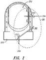
- FIG. 2 illustrates a pod which may hold a gimbaled system with an optical coudé path in accordance with some embodiments.
- Gimbaled payload 202 may be provided in pod 205, which may be mounted on the underside of an aircraft (e.g., a helicopter or plane), although the scope of the embodiments is not limited in this respect.
- Optical counature path 201 may provide a data communication path with a gimbaled payload 202.
- gimbaled payload 202 may correspond to gimbaled payload 102 ( FIG. 1 )
- optical counature path 201 may correspond to optical coudé path 101 ( FIG. 1
- mirrors 203 may correspond to mirrors 103 ( FIG. 1 ).
- optical coudé path 201 may include three mirrors 203 to provide a communication path through azimuth axis 206 and elevation axis 204 of gimbaled payload 202. In this way, gimbaled payload 102 may rotate in azimuth without restriction to provide greater than 360 degrees of continuous rotations.
- optical coudé path 201 may be provided through holes in the center of bearings of azimuth axis 206 and elevation axis 204 of gimbaled payload 202, although the scope of the embodiments is not limited in this respect.
- prisms may be used instead of mirrors 203.
Landscapes
- Engineering & Computer Science (AREA)
- Radar, Positioning & Navigation (AREA)
- Remote Sensing (AREA)
- Physics & Mathematics (AREA)
- General Physics & Mathematics (AREA)
- Computer Networks & Wireless Communication (AREA)
- Automation & Control Theory (AREA)
- Electromagnetism (AREA)
- Optical Communication System (AREA)
- Optical Radar Systems And Details Thereof (AREA)
Description
- Some embodiments pertain to gimbaled systems. Some embodiments pertain to gimbaled imaging systems. Some embodiments pertain to gimbaled laser imaging systems that use Laser Detection and Ranging (LADAR).
- Some embodiments pertain to gimbaled systems. Some embodiments pertain to gimbaled imaging systems. Some embodiments pertain to gimbaled laser imaging systems that use Laser Detection and Ranging (LADAR).
-
US6288381B1 describes an alignment and stabilization system that automatically aligns and stabilizes off-gimbal electro-optical passive and active sensors.US2003174315A1 describes a multi-emitter boresight reference source comprising first and second mechanisms for transmitting respective first and second portions of electromagnetic energy and a third mechanism for combining the first and second portions. - One issue with gimbaled systems is the transfer of data across the gimbal axes. Many conventional gimbaled systems use electrical slip rings or harnesses to transfer data cross the gimbal axes. For large amounts of data, electrical slip rings become more complex and may be less reliable. Harnesses become larger and induce undesired torque on the gimbaled system.
- Thus, there are general needs for gimbaled systems and methods to transfer large amounts of data across the gimbal axes. There are also general needs for gimbaled systems and methods to transfer large amounts of data across the gimbal axes without the use of electrical slip rings or harnesses.
-
-
FIG. 1 illustrates a gimbaled system with an optical coudé path in accordance with some embodiments; and -
FIG. 2 illustrates a pod which may hold a gimbaled system with an optical coudé path in accordance with some embodiments. - The following description and the drawings sufficiently illustrate specific embodiments to enable those skilled in the art to practice them. Other embodiments may incorporate structural, logical, electrical, process, and other changes. Examples merely typify possible variations. Individual components and functions are optional unless explicitly required, and the sequence of operations may vary. Portions and features of some embodiments may be included in, or substituted for, those of other embodiments. The scope of the invention is defined by the appended claims.
-
FIG. 1 illustrates a gimbaled system with an optical coudé path in accordance with some embodiments.Gimbaled system 100 includes a plurality of on-gimbal elements withingimbaled payload 102 and a plurality of off-gimbal elements located external to gimbaledpayload 102.Gimbaled system 100 also includesoptical coudé path 101 to provide a data communication path between some of the elements located ongimbaled payload 102 and some of the elements located off gimbaledpayload 102. In some embodiments, gimbaledsystem 100 includes off-gimbal communication laser 108 to transmit information, such as modulatedcontrol data 110, viacoudé path 101.Gimbaled system 100 may also include on-gimbal communication detector 112 to detect data, such as modulatedcontrol data 110, received acrosscoudé path 101.Optical coudé path 101 allows large amounts of data to be transferred across gimbal axes without high data rate multi-channel electrical slip rings or torque inducing harnesses. - In some embodiments, optical
coudé path 101 includes at least two mirrors 103 to provide a communication path through an azimuth axis and an elevation axis ofgimbaled payload 102. In some embodiments, a bi-directional communication path may be provided, although the scope of the embodiments is not limited in this respect. These embodiments are discussed in more detail below. - In some embodiments, off-
gimbal communication laser 108 may generate an auto-alignment beam to aligntransmit path 124 and receivepath 126 of gimbaledsystem 100. The auto-alignment beam may be modulated to communicatecontrol data 110 viacoudé path 101. In these embodiments, gimbaledsystem 100 may also includealignment detector 130 to detect wavelengths of the auto-alignment beam to indicate when transmitpath 124 and receivepath 126 are aligned. In these embodiments, off-gimbal communication laser 108 serves as both a data communication laser and an auto-alignment laser. In some alternate examples which do not form part of the present invention, a separate auto-alignment laser may be used, which may be provided off gimbal or on gimbal. In some of these embodiments, auto alignment with ten micro-radians may be achieved to correct for cross gimbal errors, although the scope of the embodiments is not limited in this respect. - In some embodiments,
gimbaled system 100 may also include on-gimbal communication laser 114 to transmit data, such asmodulated camera data 116, viacoudé path 101.Gimbaled system 100 may also include off-gimbal communication detector 118 to detect data, such as modulatedcamera data 116, received viacoudé path 101. These embodiments may allow large amounts of video data to be transferred off gimbal viaoptical coudé path 101. In some embodiments, data transfer rates of up to 2 Giga-bits-per-second (Gbps) or greater may be achieved. In embodiments that include off-gimbal communication laser 108 and on-gimbal communication detector 112, a bi-directional communication of data may be achieved to allowcommand data 110 to be transferred on gimbal. In these embodiments, on-gimbal communication detector 112 and off-gimbal communication detector 118 may include circuitry to detect and demodulate the received laser wavelengths.
In some embodiments,gimbaled system 100 may includedesignator laser 120 configured to illuminate (i.e., designate) a target region by transmittinglaser wavelengths 121 alongtransmit path 124. The target region may be on the ground (e.g., to designate a building or vehicle) or on a body of water (e.g., designate a watercraft or vessel).In these embodiments,gimbaled system 100 may be a laser designation system, although the scope of the embodiments is not limited in this respect. In some embodiments,designator laser 120 may be provided off-gimbal 102 and the laser wavelengths generated bydesignator laser 120 may be provided viacoudé path 101. - In some embodiments,
gimbaled system 100 may also include focal plane array (FPA) 128 to convertreturn laser wavelengths 127 received through receivepath 126 to electrical signals. In some embodiments,gimbaled system 100 may also include on-gimbal processing circuitry 136 to generate data such ascamera data 116 from the electrical signals for use in modulation of laser wavelengths generated by on-gimbal communication laser 114 for transmission viaoptical coudé path 101 to the off-gimbal communication detector 118.Laser wavelengths 127 received through receivepath 126 may be received throughlens 156 of gimbaledpayload 102. - In some alternate embodiments,
designator laser 120 may be configured as a Laser Detection and Ranging (LADAR) laser to transmit LADAR signals, which may include pulsed laser wavelengths for ranging and imaging. In these embodiments,camera data 116 may comprise LADAR data. In these embodiments, the LADAR signals may comprise pulsed laser wavelengths to simultaneously obtain target range information and target images. In these embodiments,camera data 116 may include video imaging and/or still photographic data from the target region. In these embodiments,gimbaled system 100 may be a laser imaging system, although the scope of the embodiments is not limited in this respect. - In some embodiments,
control data 110 may include command signals ton control one or more functional elements located ongimbaled payload 102. For example,control data 110 may be used to switch between one of a plurality of on-gimbal cameras provided ongimbaled payload 102.Control data 110 may also be used to control movement of gimbaledpayload 102 within its pod. In some embodiments,control data 110 may be used to control movable optical elements located ongimbaled payload 102. -
Gimbaled system 100 may also includesystem controller 138 located off gimbal to providecontrol data 110 to off-gimbal communication laser 108 for modulation and transmission viacoudé path 101.Gimbaled system 100 may also include on-gimbal controller 134 to receive detectedcontrol data 110 from on-gimbal communication detector 112.System controller 138 may also be configured to receive detectedcamera data 116 from off-gimbal communication detector 118, although detectedcamera data 116 may be provided to other system elements not separately illustrated. - In some embodiments, on-
gimbal controller 134 may be configured to provide data, such as navigational data that may be obtained by navigational elements ofgimbaled payload 102, to on-gimbal communication laser 114 for transmission viacoudé path 101, although the scope of the embodiments is not limited in this respect. For clarity, the signal path between on-gimbal controller 134 and on-gimbal communication laser 114 is not separately illustrated. - On-
gimbal controller 134 may also be configured to receive an indication fromalignment detector 130 when alignment is detected and may provide the indication viacoudé path 101, although the scope of the embodiments is not limited in this respect. For clarity, the signal path between on-gimbal controller 134 andalignment detector 130 is not separately illustrated. - As illustrated in
FIG. 1 ,gimbaled system 100 may include various optical elements to combine and/or separate the various laser wavelengths for performing the functions described herein. In some embodiments,gimbaled system 100 may includebeam combiner 140 located off gimbal to combine laser wavelengths generated by off-gimbal communication laser 108 with laser wavelengths generated by designator laser 120 (or in some embodiments the LADAR laser) for subsequent transmission viacoudé path 101. -
Gimbaled system 100 may also includebeam splitter 142 located off gimbal to direct laser wavelengths generated by on-gimbal communication laser 114 carryingcamera data 116 received viacoudé path 101 to off-gimbal communication detector 118. -
Gimbaled system 100 may also includebeam splitter 144 located on gimbal to direct laser wavelengths generated by off-gimbal communication laser 108 carryingcontrol data 110 received viacoudé path 101 to on-gimbal communication detector 112.Beam splitter 144 may be configured to direct a portion of the laser wavelengths carryingcontrol data 110 to on-gimbal communication detector 112 and to direct another portion of the laser wavelengths that comprise the auto-alignment beam toalignment detector 130. In these embodiments, the laser wavelengths carrying thecontrol data 110 are also used as the auto alignment beam.Beam splitter 144 accordingly directs a portion of the energy to on-gimbal communication detector 112 and a portion of the energy for direction toalignment detector 130. -
Gimbaled system 100 may also includebeam combiner 148 located on gimbal to provide laser wavelengths generated by on-gimbal communication laser 114 for subsequent transmission viacoudé path 101. In these embodiments,beam combiner 148 may be configured to allow passage of laser wavelengths generated byLADAR laser 120 received viacoudé path 101. -
Gimbaled system 100 may also includebeam splitter 146 located on gimbal to direct wavelengths of the auto-alignment beam generated by offgimbal communication laser 108 toalignment detector 130.Beam splitter 146 may also be configured to allow wavelengths generated by on-gimbal communication laser 114 to pass. - In these embodiments,
beam splitters beam combiners - In some embodiments, referred to as different-wavelength embodiments, on-
gimbal communication laser 114 and off-gimbal communication laser 108 transmit modulated data at different laser wavelengths. In these different-wavelength embodiments,beam splitters beam combiners gimbal communication laser 114 and off-gimbal communication laser 108. In these different-wavelength embodiments,beam splitters Beam combiner 140 may be configured to reflect substantially all energy of the wavelengths generated by offgimbal communication laser 108 and transmit the wavelengths generated byLADAR laser 120.Beam splitter 144 may be configured to transmit the wavelengths generated by offgimbal communication laser 108 to on-gimbal communication detector 112 and reflect the wavelengths generated byLADAR laser 102 to an illuminator. In these different-wavelength embodiments,beam combiner 148 may be configured to reflect the wavelengths generated by on-gimbal communication laser 114 and transmit the wavelengths generated byLADAR laser 102 to the illuminator as shown.Beam splitter 144 may additionally be configured to reflect the wavelengths generated by on-gimbal communication laser 114 viaoptical coudé path 101 to off-gimbal communication detector 118. In these different-wavelength embodiments,beam splitter 142 may be configured to reflect the wavelengths generated by on-gimbal communication laser 114 and transmit the wavelengths generated byLADAR laser 102. - In some embodiments, referred to as same-wavelength embodiments, on-
gimbal communication laser 114 and off-gimbal communication laser 108 transmit modulated data at the same laser wavelengths. In these same-wavelength embodiments,beam splitters beam combiners gimbal communication laser 114 and off-gimbal communication laser 108. In these same-wavelength embodiments,beam splitters gimbal communication laser 108 and on-gimbal communication laser 114. For example,beam splitters gimbal communication laser 108 and on-gimbal communication laser 114 may be timed and/or rotated to allow on-gimbal communication detector 112 to detect the modulated wavelengths from off-gimbal communication laser 108 and to allow off-gimbal communication detector 118 to separately detect the modulated wavelengths from on-gimbal communication laser 114. In some of these same-wavelength embodiments, on-gimbal communication detector 112 may be shielded or turned off when on-gimbal communication laser 114 is transmitting, and off-gimbal communication detector 118 may be shielded or turned off when off-gimbal communication laser 108 is transmitting, although the scope of the embodiments is not limited in this respect. -
Gimbaled system 100 may also includebeam steering circuitry 132 located off gimbal configured to controlbeam steering mirror 133.Beam steering circuitry 132 may be responsive to signals fromsystem controller 138 to align laser wavelengths generated bydesignator laser 120 and wavelengths generated by the off-gimbal communication laser 108 withcoudé path 101. - In some embodiments,
gimbaled system 100 may include elements of an optical telescope such as primary reflector 151,secondary reflector 152,tertiary reflector 153, andquaternary reflector 154. In these embodiments, primary reflector 151,secondary reflector 152,tertiary reflector 153, andquaternary reflector 154 may direct laser wavelengths fromdesignator laser 120 or the LADAR laser at a target region and may direct returnlaser wavelengths 127 received from the target region toLADAR FPA 128. In these embodiments, gimbaled payload may includereflective elements optical elements 158 to direct and/or focusreturn laser wavelengths 127 onLADAR FPA 136.Reflective element 159 may comprise a mirror with a hole to allowlaser wavelengths 121 fromLADAR laser 120 to pass. - Although
FIG. 1 illustrates embodiments of a three-mirror telescope imager, the scope of the invention is not limited in this respect. Other embodiments are applicable to two-mirror telescopes as well as refractive telescopes and imaging devices. - In some embodiments, a method of transferring larges amounts of data across gimbal axes without high data rate multi-channel electrical slip rings or torque inducing harnesses is provided. In these embodiments,
optical coudé path 101 may be provided withingimbaled payload 102.Camera data 116 may be modulated with on-gimbal communication laser 114, and the modulated camera data may be directed viaoptical coudé path 101 to off-gimbal communication detector 118. In some embodiments, an auto-alignment beam may be directed viaoptical coudé path 101 from off-gimbal to an auto alignment detector located on-gimbal. On-gimbal communication laser 108 may generate the auto alignment beam and control data controldata 110 may be modulated with on-gimbal communication laser 108. The modulated control data may be directed viacoudé path 101 for detection by on-gimbal communication detector 112. The control data may control one or more on-gimbal elements ofgimbaled system 102. - In some embodiments, LADAR wavelengths may be directed via
coudé path 101 to a plurality of on-gimbal reflectors to image a target region. Return LADAR wavelengths from the target region may be directed toLADAR FPA 128 to generate the camera data. The camera data may comprises target range and imaging data for transmission off gimbal via theoptical coudé path 101. - In
FIG. 1 ,LADAR FPA 136,optical elements 158 andprocessing circuitry 128 are shown outsidegimbaled payload 102 for illustrative purposes. In actual embodiments,LADAR FPA 136,optical elements 158 andprocessing circuitry 128 are located on-gimbal. -
FIG. 2 illustrates a pod which may hold a gimbaled system with an optical coudé path in accordance with some embodiments.Gimbaled payload 202 may be provided inpod 205, which may be mounted on the underside of an aircraft (e.g., a helicopter or plane), although the scope of the embodiments is not limited in this respect. Opticalcoudé path 201 may provide a data communication path with agimbaled payload 202. In these embodiments,gimbaled payload 202 may correspond to gimbaled payload 102 (FIG. 1 ),optical coudé path 201 may correspond to optical coudé path 101 (FIG. 1 , and mirrors 203 may correspond to mirrors 103 (FIG. 1 ). - In these embodiments,
optical coudé path 201 may include threemirrors 203 to provide a communication path throughazimuth axis 206 andelevation axis 204 ofgimbaled payload 202. In this way,gimbaled payload 102 may rotate in azimuth without restriction to provide greater than 360 degrees of continuous rotations. In some embodiments,optical coudé path 201 may be provided through holes in the center of bearings ofazimuth axis 206 andelevation axis 204 ofgimbaled payload 202, although the scope of the embodiments is not limited in this respect. In some embodiments, prisms may be used instead ofmirrors 203.
Claims (17)
- A gimbaled system (100) comprising:an optical coudé path (101) to provide a bi-directional data communication path with a gimbaled payload (102);an off-gimbal communication laser (108) to transmit modulated control data (110) on an auto-alignment beam via the coudé path (101); andan on-gimbal communication detector (112) to detect the control data (110) received across the coudé path (101);an on-gimbal communication laser (114) to transmit modulated data (116) generated from one or more functional elements of the gimbaled payload (102) via the coudé path (101); andan off-gimbal communication detector (118) to detect the modulated data (116) transmitted by the on-gimbal communication laser (114) and received via the coudé path (101),wherein the off-gimbal communication laser (108) is configured to generate the auto-alignment beam to align a transmit path (124) and a receive path (126) of the gimballed system (100), the auto-alignment beam being modulated to communicate the control data via the coudé path (101), the control data including command signals to control the one or more functional elements of the gimbaled payload (102).
- The system of claim 1 wherein the optical coudé path includes at least two mirrors to provide a bi-directional communication path through an azimuth axis and an elevation axis of the gimbaled payload.
- The system of claim 1
further comprising an alignment detector to detect wavelengths of the auto-alignment beam to indicate when the transmit and receive paths are aligned. - The system of claim 3 wherein the modulated data transmitted by the on-gimbal communication laser comprises camera data.
- The system of claim 4 further comprising:a designator laser configured to illuminate a target region by transmitting laser wavelengths along the transmit path; anda focal plane array (FPA) to convert return laser wavelengths received through the receive path to electrical signals; andon-gimbal processing circuitry to generate the camera data from the electrical signals for use in modulation of laser wavelengths generated by the on-gimbal communication laser for transmission via the optical coudé path to the off-gimbal communication detector.
- The system of claim 5 wherein the designator laser is provided off-gimbal and the laser wavelengths generated by the designator laser are provided via the coudé path.
- The system of claim 6 wherein the designator laser is configured as a Laser Detection and Ranging (LADAR) laser to transmit LADAR signals, and
wherein the camera data further comprises target range and imaging information data. - The system of claim 4 wherein the control data includes command signals to switch between one of a plurality of on-gimbal cameras provided on the gimbaled payload and control signals to control movement of the gimbaled payload within a pod.
- The system of claim 8 further comprising:a system controller located off gimbal to provide the control data to the off-gimbal communication laser for modulation and transmission via the coudé path; andan on-gimbal controller to receive detected control data from the on-gimbal communication detector.
- The system of claim 9 wherein the on-gimbal controller is configured to provide navigation data obtained by the gimbaled payload to the on-gimbal communication laser for transmission via the coudé path, and
wherein the on-gimbal controller is configured to receive an indication from the alignment detector when alignment is detected and provide the indication via the coudé path. - The system of claim 4 further comprising:a first beam combiner located off gimbal to combine laser wavelengths generated by the off-gimbal communication laser with laser wavelengths generated by a Laser Detection and Ranging (LADAR) laser for subsequent transmission via the coudé path;a first beam splitter located off gimbal to direct laser wavelengths carrying the camera data received via the coudé path to the off-gimbal communication detector;a second beam splitter located on gimbal to direct laser wavelengths carrying the control data received via the coudé path to the on-gimbal communication detector;a second beam combiner located on gimbal to provide laser wavelengths generated by the on-gimbal communication laser for subsequent transmission via the coudé path,wherein the second beam combiner is configured to allow passage of laser wavelengths generated by the LADAR laser received via the coudé path.
- The system of claim 11 further comprising a third beam splitter located on gimbal to direct wavelengths of the auto-alignment beam to the alignment detector,
wherein the second beam splitter is configured to direct a portion of the laser wavelengths carrying the control data to the on-gimbal communication detector and configured to direct another portion of the laser wavelengths that comprise the auto-alignment beam to the alignment detector. - The system of claim 4 wherein the on-gimbal communication laser and the off-gimbal communication laser transmit modulated data at a same laser wavelength.
- The system of claim 4 wherein the on-gimbal communication laser and the off-gimbal communication laser transmit modulated data at different laser wavelengths.
- The system of claim 10 further comprising beam steering circuitry located off gimbal configured to control a beam steering mirror to align the laser wavelengths generated by the LADAR laser and wavelengths generated by the off-gimbal communication laser with the coudé path.
- A method of transferring data across gimbal axes comprising:providing an optical coudé path (101) to provide a bi-directional data communication path with a gimbaled payload (102);transmitting modulated camera data from one or more on-gimbal functional elements with an on-gimbal communication laser (104) via the optical coudé path to an off-gimbal communication detector (118);directing an auto-alignment beam via the optical coudé path from off-gimbal to an auto alignment detector located on-gimbal; andmodulating control data on the auto alignment beam and transmitting the modulated control data (110) via the coude path for detection by an on-gimbal communication detector, the control data being configured to control the one or more on-gimbal functional elements of the gimbaled system,wherein an off-gimbal communication laser (108) is configured to generate the auto-alignment beam to align a transmit path and a receive path of the gimballed system.
- The method of claim 16 further comprising:directing Laser Detection and Ranging (LADAR) wavelengths via the coudé path to a plurality of on-gimbal reflectors to image a target region; anddirecting return LADAR wavelengths from the target region to a LADAR focal plane array to generate the camera data,wherein the camera data comprises target range and imaging data for transmission off gimbal via the optical coudé path.
Applications Claiming Priority (2)
| Application Number | Priority Date | Filing Date | Title |
|---|---|---|---|
| US12/323,967 US7929125B2 (en) | 2008-11-26 | 2008-11-26 | Gimbaled system with optical coudé path and method transferring data |
| PCT/US2009/006189 WO2010068240A1 (en) | 2008-11-26 | 2009-11-19 | Gimbaled system with optical coudé path and method transferring data |
Publications (3)
| Publication Number | Publication Date |
|---|---|
| EP2352966A1 EP2352966A1 (en) | 2011-08-10 |
| EP2352966A4 EP2352966A4 (en) | 2016-04-27 |
| EP2352966B1 true EP2352966B1 (en) | 2022-08-24 |
Family
ID=42195952
Family Applications (1)
| Application Number | Title | Priority Date | Filing Date |
|---|---|---|---|
| EP09832221.7A Active EP2352966B1 (en) | 2008-11-26 | 2009-11-19 | Gimbaled system with optical coudé path and method transferring data |
Country Status (3)
| Country | Link |
|---|---|
| US (1) | US7929125B2 (en) |
| EP (1) | EP2352966B1 (en) |
| WO (1) | WO2010068240A1 (en) |
Families Citing this family (13)
| Publication number | Priority date | Publication date | Assignee | Title |
|---|---|---|---|---|
| US8396090B2 (en) * | 2009-09-25 | 2013-03-12 | The Boeing Company | Window mounted beam director |
| US20130021474A1 (en) * | 2011-07-20 | 2013-01-24 | Raytheon Company | Rolling-shutter imaging system with synchronized scanning illumination and methods for higher-resolution imaging |
| US8982458B2 (en) | 2011-09-27 | 2015-03-17 | The Boeing Company | Optical telescope for gimbaled systems |
| DE102012019940A1 (en) * | 2012-10-11 | 2014-04-17 | Mbda Deutschland Gmbh | Laser beam directing system and method for aligning optical components of the laser beam directing system |
| US10145944B1 (en) | 2014-05-02 | 2018-12-04 | Kla-Tencor Corporation | System and method for LADAR-based optic alignment and characterization |
| CN104807437B (en) * | 2015-03-06 | 2017-06-16 | 北方民族大学 | A kind of multi-pass self calibration laser tracking measurement system |
| US9740200B2 (en) | 2015-12-30 | 2017-08-22 | Unmanned Innovation, Inc. | Unmanned aerial vehicle inspection system |
| US9513635B1 (en) | 2015-12-30 | 2016-12-06 | Unmanned Innovation, Inc. | Unmanned aerial vehicle inspection system |
| US9618940B1 (en) | 2015-12-31 | 2017-04-11 | Unmanned Innovation, Inc. | Unmanned aerial vehicle rooftop inspection system |
| US11029352B2 (en) | 2016-05-18 | 2021-06-08 | Skydio, Inc. | Unmanned aerial vehicle electromagnetic avoidance and utilization system |
| US10712532B2 (en) | 2017-04-24 | 2020-07-14 | Government Of The United States, As Represented By The Secretary Of The Air Force | Quad-axis rotatable coudé path |
| CN112082514B (en) * | 2020-09-09 | 2022-04-19 | 易思维(杭州)科技有限公司 | Portable angle measuring instrument and using method thereof |
| US20230065240A1 (en) * | 2021-08-25 | 2023-03-02 | The United States of America As Represented By The Director Of The National Geospatial-Intelligence | Method and apparatus for the display of volumetric solids using distributed photochromic compounds |
Family Cites Families (8)
| Publication number | Priority date | Publication date | Assignee | Title |
|---|---|---|---|---|
| US6268944B1 (en) * | 1998-02-19 | 2001-07-31 | Com Dev Limited | Free-space optical lasercom system |
| US6288381B1 (en) * | 1999-08-26 | 2001-09-11 | Raytheon Company | Integrated system for line-of-sight stabilization and auto-alignment of off-gimbal passive and active electro-optical sensors |
| US6765663B2 (en) * | 2002-03-14 | 2004-07-20 | Raytheon Company | Efficient multiple emitter boresight reference source |
| US6961171B2 (en) * | 2002-10-17 | 2005-11-01 | Raytheon Company | Phase conjugate relay mirror apparatus for high energy laser system and method |
| US7308342B2 (en) * | 2004-01-23 | 2007-12-11 | Rafael Armament Development Authority Ltd. | Airborne reconnaissance system |
| US7400384B1 (en) * | 2005-04-12 | 2008-07-15 | Lockheed Martin Corporation | Method and apparatus for varying pixel spatial resolution for ladar systems |
| US20080002176A1 (en) * | 2005-07-08 | 2008-01-03 | Lockheed Martin Corporation | Lookdown and loitering ladar system |
| US7626152B2 (en) * | 2006-08-16 | 2009-12-01 | Raytheon Company | Beam director and control system for a high energy laser within a conformal window |
-
2008
- 2008-11-26 US US12/323,967 patent/US7929125B2/en active Active
-
2009
- 2009-11-19 EP EP09832221.7A patent/EP2352966B1/en active Active
- 2009-11-19 WO PCT/US2009/006189 patent/WO2010068240A1/en not_active Ceased
Also Published As
| Publication number | Publication date |
|---|---|
| EP2352966A1 (en) | 2011-08-10 |
| EP2352966A4 (en) | 2016-04-27 |
| US20100128244A1 (en) | 2010-05-27 |
| US7929125B2 (en) | 2011-04-19 |
| WO2010068240A1 (en) | 2010-06-17 |
Similar Documents
| Publication | Publication Date | Title |
|---|---|---|
| US7929125B2 (en) | Gimbaled system with optical coudé path and method transferring data | |
| US6347001B1 (en) | Free-space laser communication system having six axes of movement | |
| EP2564147B1 (en) | Optical transceiver built-in test (bit) | |
| EP3465272B1 (en) | High-performance beam director for high-power laser systems or other systems | |
| JP4729104B2 (en) | Acquisition, indication, and tracking architecture for laser communications | |
| EP2588917B1 (en) | Line of sight stabilization system | |
| EP2115515B1 (en) | Common-aperture optical system incorporating a light sensor and a light source | |
| JP6654736B2 (en) | A system that combines imaging and laser communication | |
| JP2022517505A (en) | Two-mirror tracking system for free-space optical communication | |
| EP3966516B1 (en) | Beam director for high-energy laser (hel) weapon | |
| US6347010B1 (en) | Periscope using common optical path to have stabilized panoramic view | |
| EP2590005B1 (en) | Faceted retro-mirror for line-of-sight jitter sensing | |
| US7657183B2 (en) | Method and apparatus for hemispherical retargeting | |
| US7920794B1 (en) | Free space optical communication | |
| US12095508B2 (en) | Multi-link optical terabit terminal | |
| US11675145B2 (en) | Injection of a beam of radiation into an optical fibre | |
| US12061334B2 (en) | Optical scanning system using micro-electro-mechanical system (mems) micro-mirror arrays (MMAs) | |
| WO2022076187A1 (en) | Optical sensor with jitter stabilization | |
| RU2396573C2 (en) | Electro-optical sighting system | |
| US11841217B2 (en) | WFOV backward-propagating active-to-passive autoalignment system | |
| Brown et al. | Next generation laser tracker concepts | |
| WO2025243192A1 (en) | Improved free-space optical transceiver | |
| Biswas et al. | Optical Design of an Optical Communications Terminal | |
| RU164706U1 (en) | MULTI-CHANNEL OPTICAL-LOCATION SYSTEM |
Legal Events
| Date | Code | Title | Description |
|---|---|---|---|
| PUAI | Public reference made under article 153(3) epc to a published international application that has entered the european phase |
Free format text: ORIGINAL CODE: 0009012 |
|
| 17P | Request for examination filed |
Effective date: 20110607 |
|
| AK | Designated contracting states |
Kind code of ref document: A1 Designated state(s): AT BE BG CH CY CZ DE DK EE ES FI FR GB GR HR HU IE IS IT LI LT LU LV MC MK MT NL NO PL PT RO SE SI SK SM TR |
|
| DAX | Request for extension of the european patent (deleted) | ||
| RA4 | Supplementary search report drawn up and despatched (corrected) |
Effective date: 20160331 |
|
| RIC1 | Information provided on ipc code assigned before grant |
Ipc: G01C 21/28 20060101ALI20160323BHEP Ipc: G01C 3/00 20060101AFI20160323BHEP Ipc: G01S 7/481 20060101ALI20160323BHEP Ipc: G01S 17/02 20060101ALI20160323BHEP |
|
| STAA | Information on the status of an ep patent application or granted ep patent |
Free format text: STATUS: EXAMINATION IS IN PROGRESS |
|
| 17Q | First examination report despatched |
Effective date: 20181128 |
|
| GRAP | Despatch of communication of intention to grant a patent |
Free format text: ORIGINAL CODE: EPIDOSNIGR1 |
|
| STAA | Information on the status of an ep patent application or granted ep patent |
Free format text: STATUS: GRANT OF PATENT IS INTENDED |
|
| INTG | Intention to grant announced |
Effective date: 20220316 |
|
| RIN1 | Information on inventor provided before grant (corrected) |
Inventor name: ROBERTS, THOMAS E. Inventor name: RINKER, ROBERT Inventor name: ANTHONY, DAVID G. Inventor name: MARKASON, DAVID J. Inventor name: WERRIES, WILLIAM D. Inventor name: KOEHLER, FREDERICK B. |
|
| GRAS | Grant fee paid |
Free format text: ORIGINAL CODE: EPIDOSNIGR3 |
|
| GRAA | (expected) grant |
Free format text: ORIGINAL CODE: 0009210 |
|
| STAA | Information on the status of an ep patent application or granted ep patent |
Free format text: STATUS: THE PATENT HAS BEEN GRANTED |
|
| AK | Designated contracting states |
Kind code of ref document: B1 Designated state(s): AT BE BG CH CY CZ DE DK EE ES FI FR GB GR HR HU IE IS IT LI LT LU LV MC MK MT NL NO PL PT RO SE SI SK SM TR |
|
| REG | Reference to a national code |
Ref country code: GB Ref legal event code: FG4D |
|
| REG | Reference to a national code |
Ref country code: CH Ref legal event code: EP |
|
| REG | Reference to a national code |
Ref country code: DE Ref legal event code: R096 Ref document number: 602009064572 Country of ref document: DE |
|
| REG | Reference to a national code |
Ref country code: IE Ref legal event code: FG4D |
|
| REG | Reference to a national code |
Ref country code: AT Ref legal event code: REF Ref document number: 1513939 Country of ref document: AT Kind code of ref document: T Effective date: 20220915 |
|
| REG | Reference to a national code |
Ref country code: LT Ref legal event code: MG9D |
|
| REG | Reference to a national code |
Ref country code: NL Ref legal event code: MP Effective date: 20220824 |
|
| PG25 | Lapsed in a contracting state [announced via postgrant information from national office to epo] |
Ref country code: SE Free format text: LAPSE BECAUSE OF FAILURE TO SUBMIT A TRANSLATION OF THE DESCRIPTION OR TO PAY THE FEE WITHIN THE PRESCRIBED TIME-LIMIT Effective date: 20220824 Ref country code: PT Free format text: LAPSE BECAUSE OF FAILURE TO SUBMIT A TRANSLATION OF THE DESCRIPTION OR TO PAY THE FEE WITHIN THE PRESCRIBED TIME-LIMIT Effective date: 20221226 Ref country code: NO Free format text: LAPSE BECAUSE OF FAILURE TO SUBMIT A TRANSLATION OF THE DESCRIPTION OR TO PAY THE FEE WITHIN THE PRESCRIBED TIME-LIMIT Effective date: 20221124 Ref country code: NL Free format text: LAPSE BECAUSE OF FAILURE TO SUBMIT A TRANSLATION OF THE DESCRIPTION OR TO PAY THE FEE WITHIN THE PRESCRIBED TIME-LIMIT Effective date: 20220824 Ref country code: LV Free format text: LAPSE BECAUSE OF FAILURE TO SUBMIT A TRANSLATION OF THE DESCRIPTION OR TO PAY THE FEE WITHIN THE PRESCRIBED TIME-LIMIT Effective date: 20220824 Ref country code: LT Free format text: LAPSE BECAUSE OF FAILURE TO SUBMIT A TRANSLATION OF THE DESCRIPTION OR TO PAY THE FEE WITHIN THE PRESCRIBED TIME-LIMIT Effective date: 20220824 Ref country code: FI Free format text: LAPSE BECAUSE OF FAILURE TO SUBMIT A TRANSLATION OF THE DESCRIPTION OR TO PAY THE FEE WITHIN THE PRESCRIBED TIME-LIMIT Effective date: 20220824 Ref country code: ES Free format text: LAPSE BECAUSE OF FAILURE TO SUBMIT A TRANSLATION OF THE DESCRIPTION OR TO PAY THE FEE WITHIN THE PRESCRIBED TIME-LIMIT Effective date: 20220824 |
|
| REG | Reference to a national code |
Ref country code: AT Ref legal event code: MK05 Ref document number: 1513939 Country of ref document: AT Kind code of ref document: T Effective date: 20220824 |
|
| PG25 | Lapsed in a contracting state [announced via postgrant information from national office to epo] |
Ref country code: PL Free format text: LAPSE BECAUSE OF FAILURE TO SUBMIT A TRANSLATION OF THE DESCRIPTION OR TO PAY THE FEE WITHIN THE PRESCRIBED TIME-LIMIT Effective date: 20220824 Ref country code: IS Free format text: LAPSE BECAUSE OF FAILURE TO SUBMIT A TRANSLATION OF THE DESCRIPTION OR TO PAY THE FEE WITHIN THE PRESCRIBED TIME-LIMIT Effective date: 20221224 Ref country code: HR Free format text: LAPSE BECAUSE OF FAILURE TO SUBMIT A TRANSLATION OF THE DESCRIPTION OR TO PAY THE FEE WITHIN THE PRESCRIBED TIME-LIMIT Effective date: 20220824 Ref country code: GR Free format text: LAPSE BECAUSE OF FAILURE TO SUBMIT A TRANSLATION OF THE DESCRIPTION OR TO PAY THE FEE WITHIN THE PRESCRIBED TIME-LIMIT Effective date: 20221125 |
|
| PG25 | Lapsed in a contracting state [announced via postgrant information from national office to epo] |
Ref country code: SM Free format text: LAPSE BECAUSE OF FAILURE TO SUBMIT A TRANSLATION OF THE DESCRIPTION OR TO PAY THE FEE WITHIN THE PRESCRIBED TIME-LIMIT Effective date: 20220824 Ref country code: RO Free format text: LAPSE BECAUSE OF FAILURE TO SUBMIT A TRANSLATION OF THE DESCRIPTION OR TO PAY THE FEE WITHIN THE PRESCRIBED TIME-LIMIT Effective date: 20220824 Ref country code: DK Free format text: LAPSE BECAUSE OF FAILURE TO SUBMIT A TRANSLATION OF THE DESCRIPTION OR TO PAY THE FEE WITHIN THE PRESCRIBED TIME-LIMIT Effective date: 20220824 Ref country code: CZ Free format text: LAPSE BECAUSE OF FAILURE TO SUBMIT A TRANSLATION OF THE DESCRIPTION OR TO PAY THE FEE WITHIN THE PRESCRIBED TIME-LIMIT Effective date: 20220824 Ref country code: AT Free format text: LAPSE BECAUSE OF FAILURE TO SUBMIT A TRANSLATION OF THE DESCRIPTION OR TO PAY THE FEE WITHIN THE PRESCRIBED TIME-LIMIT Effective date: 20220824 |
|
| REG | Reference to a national code |
Ref country code: DE Ref legal event code: R097 Ref document number: 602009064572 Country of ref document: DE |
|
| PG25 | Lapsed in a contracting state [announced via postgrant information from national office to epo] |
Ref country code: SK Free format text: LAPSE BECAUSE OF FAILURE TO SUBMIT A TRANSLATION OF THE DESCRIPTION OR TO PAY THE FEE WITHIN THE PRESCRIBED TIME-LIMIT Effective date: 20220824 Ref country code: EE Free format text: LAPSE BECAUSE OF FAILURE TO SUBMIT A TRANSLATION OF THE DESCRIPTION OR TO PAY THE FEE WITHIN THE PRESCRIBED TIME-LIMIT Effective date: 20220824 |
|
| PG25 | Lapsed in a contracting state [announced via postgrant information from national office to epo] |
Ref country code: MC Free format text: LAPSE BECAUSE OF FAILURE TO SUBMIT A TRANSLATION OF THE DESCRIPTION OR TO PAY THE FEE WITHIN THE PRESCRIBED TIME-LIMIT Effective date: 20220824 |
|
| PLBE | No opposition filed within time limit |
Free format text: ORIGINAL CODE: 0009261 |
|
| REG | Reference to a national code |
Ref country code: CH Ref legal event code: PL |
|
| STAA | Information on the status of an ep patent application or granted ep patent |
Free format text: STATUS: NO OPPOSITION FILED WITHIN TIME LIMIT |
|
| P01 | Opt-out of the competence of the unified patent court (upc) registered |
Effective date: 20230530 |
|
| REG | Reference to a national code |
Ref country code: BE Ref legal event code: MM Effective date: 20221130 |
|
| PG25 | Lapsed in a contracting state [announced via postgrant information from national office to epo] |
Ref country code: LI Free format text: LAPSE BECAUSE OF NON-PAYMENT OF DUE FEES Effective date: 20221130 Ref country code: CH Free format text: LAPSE BECAUSE OF NON-PAYMENT OF DUE FEES Effective date: 20221130 |
|
| 26N | No opposition filed |
Effective date: 20230525 |
|
| PG25 | Lapsed in a contracting state [announced via postgrant information from national office to epo] |
Ref country code: SI Free format text: LAPSE BECAUSE OF FAILURE TO SUBMIT A TRANSLATION OF THE DESCRIPTION OR TO PAY THE FEE WITHIN THE PRESCRIBED TIME-LIMIT Effective date: 20220824 Ref country code: LU Free format text: LAPSE BECAUSE OF NON-PAYMENT OF DUE FEES Effective date: 20221119 |
|
| PG25 | Lapsed in a contracting state [announced via postgrant information from national office to epo] |
Ref country code: IE Free format text: LAPSE BECAUSE OF NON-PAYMENT OF DUE FEES Effective date: 20221119 |
|
| PG25 | Lapsed in a contracting state [announced via postgrant information from national office to epo] |
Ref country code: BE Free format text: LAPSE BECAUSE OF NON-PAYMENT OF DUE FEES Effective date: 20221130 |
|
| PG25 | Lapsed in a contracting state [announced via postgrant information from national office to epo] |
Ref country code: HU Free format text: LAPSE BECAUSE OF FAILURE TO SUBMIT A TRANSLATION OF THE DESCRIPTION OR TO PAY THE FEE WITHIN THE PRESCRIBED TIME-LIMIT; INVALID AB INITIO Effective date: 20091119 |
|
| PG25 | Lapsed in a contracting state [announced via postgrant information from national office to epo] |
Ref country code: CY Free format text: LAPSE BECAUSE OF FAILURE TO SUBMIT A TRANSLATION OF THE DESCRIPTION OR TO PAY THE FEE WITHIN THE PRESCRIBED TIME-LIMIT Effective date: 20220824 |
|
| PG25 | Lapsed in a contracting state [announced via postgrant information from national office to epo] |
Ref country code: MK Free format text: LAPSE BECAUSE OF FAILURE TO SUBMIT A TRANSLATION OF THE DESCRIPTION OR TO PAY THE FEE WITHIN THE PRESCRIBED TIME-LIMIT Effective date: 20220824 Ref country code: IT Free format text: LAPSE BECAUSE OF FAILURE TO SUBMIT A TRANSLATION OF THE DESCRIPTION OR TO PAY THE FEE WITHIN THE PRESCRIBED TIME-LIMIT Effective date: 20220824 |
|
| PG25 | Lapsed in a contracting state [announced via postgrant information from national office to epo] |
Ref country code: TR Free format text: LAPSE BECAUSE OF FAILURE TO SUBMIT A TRANSLATION OF THE DESCRIPTION OR TO PAY THE FEE WITHIN THE PRESCRIBED TIME-LIMIT Effective date: 20220824 |
|
| PG25 | Lapsed in a contracting state [announced via postgrant information from national office to epo] |
Ref country code: BG Free format text: LAPSE BECAUSE OF FAILURE TO SUBMIT A TRANSLATION OF THE DESCRIPTION OR TO PAY THE FEE WITHIN THE PRESCRIBED TIME-LIMIT Effective date: 20220824 |
|
| PG25 | Lapsed in a contracting state [announced via postgrant information from national office to epo] |
Ref country code: MT Free format text: LAPSE BECAUSE OF FAILURE TO SUBMIT A TRANSLATION OF THE DESCRIPTION OR TO PAY THE FEE WITHIN THE PRESCRIBED TIME-LIMIT Effective date: 20220824 |
|
| PGFP | Annual fee paid to national office [announced via postgrant information from national office to epo] |
Ref country code: DE Payment date: 20251022 Year of fee payment: 17 |
|
| PGFP | Annual fee paid to national office [announced via postgrant information from national office to epo] |
Ref country code: GB Payment date: 20251023 Year of fee payment: 17 |
|
| PGFP | Annual fee paid to national office [announced via postgrant information from national office to epo] |
Ref country code: FR Payment date: 20251022 Year of fee payment: 17 |