EP2352246A1 - Multi-user mimo system, receiver apparatus and transmitter apparatus - Google Patents
Multi-user mimo system, receiver apparatus and transmitter apparatus Download PDFInfo
- Publication number
- EP2352246A1 EP2352246A1 EP09823496A EP09823496A EP2352246A1 EP 2352246 A1 EP2352246 A1 EP 2352246A1 EP 09823496 A EP09823496 A EP 09823496A EP 09823496 A EP09823496 A EP 09823496A EP 2352246 A1 EP2352246 A1 EP 2352246A1
- Authority
- EP
- European Patent Office
- Prior art keywords
- transmission
- signal
- receiver
- transmitter
- transmitters
- Prior art date
- Legal status (The legal status is an assumption and is not a legal conclusion. Google has not performed a legal analysis and makes no representation as to the accuracy of the status listed.)
- Granted
Links
- 230000005540 biological transmission Effects 0.000 claims abstract description 148
- 238000012545 processing Methods 0.000 claims abstract description 43
- 238000000926 separation method Methods 0.000 claims abstract description 32
- 238000010586 diagram Methods 0.000 description 23
- 238000001228 spectrum Methods 0.000 description 20
- 239000011159 matrix material Substances 0.000 description 16
- 238000006243 chemical reaction Methods 0.000 description 10
- 238000004891 communication Methods 0.000 description 9
- 238000012937 correction Methods 0.000 description 7
- 238000013507 mapping Methods 0.000 description 7
- 238000000034 method Methods 0.000 description 7
- 238000000411 transmission spectrum Methods 0.000 description 5
- 230000000694 effects Effects 0.000 description 4
- 238000010295 mobile communication Methods 0.000 description 4
- 239000000969 carrier Substances 0.000 description 3
- 230000003111 delayed effect Effects 0.000 description 3
- 238000001914 filtration Methods 0.000 description 3
- 230000003595 spectral effect Effects 0.000 description 3
- 238000005094 computer simulation Methods 0.000 description 2
- 238000005562 fading Methods 0.000 description 2
- 230000007274 generation of a signal involved in cell-cell signaling Effects 0.000 description 2
- 230000007774 longterm Effects 0.000 description 2
- 108010003272 Hyaluronate lyase Proteins 0.000 description 1
- 238000007476 Maximum Likelihood Methods 0.000 description 1
- 108010076504 Protein Sorting Signals Proteins 0.000 description 1
- 230000003044 adaptive effect Effects 0.000 description 1
- 238000001514 detection method Methods 0.000 description 1
- 230000006866 deterioration Effects 0.000 description 1
- 230000010363 phase shift Effects 0.000 description 1
- 238000005070 sampling Methods 0.000 description 1
Images


Classifications
-
- H—ELECTRICITY
- H04—ELECTRIC COMMUNICATION TECHNIQUE
- H04B—TRANSMISSION
- H04B7/00—Radio transmission systems, i.e. using radiation field
- H04B7/02—Diversity systems; Multi-antenna system, i.e. transmission or reception using multiple antennas
- H04B7/04—Diversity systems; Multi-antenna system, i.e. transmission or reception using multiple antennas using two or more spaced independent antennas
- H04B7/08—Diversity systems; Multi-antenna system, i.e. transmission or reception using multiple antennas using two or more spaced independent antennas at the receiving station
- H04B7/0837—Diversity systems; Multi-antenna system, i.e. transmission or reception using multiple antennas using two or more spaced independent antennas at the receiving station using pre-detection combining
- H04B7/0842—Weighted combining
- H04B7/0848—Joint weighting
- H04B7/0854—Joint weighting using error minimizing algorithms, e.g. minimum mean squared error [MMSE], "cross-correlation" or matrix inversion
-
- H—ELECTRICITY
- H04—ELECTRIC COMMUNICATION TECHNIQUE
- H04B—TRANSMISSION
- H04B7/00—Radio transmission systems, i.e. using radiation field
- H04B7/02—Diversity systems; Multi-antenna system, i.e. transmission or reception using multiple antennas
- H04B7/04—Diversity systems; Multi-antenna system, i.e. transmission or reception using multiple antennas using two or more spaced independent antennas
- H04B7/0413—MIMO systems
- H04B7/0452—Multi-user MIMO systems
-
- H—ELECTRICITY
- H04—ELECTRIC COMMUNICATION TECHNIQUE
- H04J—MULTIPLEX COMMUNICATION
- H04J11/00—Orthogonal multiplex systems, e.g. using WALSH codes
- H04J11/0023—Interference mitigation or co-ordination
- H04J11/0026—Interference mitigation or co-ordination of multi-user interference
-
- H—ELECTRICITY
- H04—ELECTRIC COMMUNICATION TECHNIQUE
- H04L—TRANSMISSION OF DIGITAL INFORMATION, e.g. TELEGRAPHIC COMMUNICATION
- H04L25/00—Baseband systems
- H04L25/02—Details ; arrangements for supplying electrical power along data transmission lines
- H04L25/0202—Channel estimation
- H04L25/024—Channel estimation channel estimation algorithms
- H04L25/0242—Channel estimation channel estimation algorithms using matrix methods
-
- H—ELECTRICITY
- H04—ELECTRIC COMMUNICATION TECHNIQUE
- H04L—TRANSMISSION OF DIGITAL INFORMATION, e.g. TELEGRAPHIC COMMUNICATION
- H04L27/00—Modulated-carrier systems
- H04L27/26—Systems using multi-frequency codes
- H04L27/2601—Multicarrier modulation systems
- H04L27/2626—Arrangements specific to the transmitter only
- H04L27/2627—Modulators
- H04L27/2634—Inverse fast Fourier transform [IFFT] or inverse discrete Fourier transform [IDFT] modulators in combination with other circuits for modulation
- H04L27/2636—Inverse fast Fourier transform [IFFT] or inverse discrete Fourier transform [IDFT] modulators in combination with other circuits for modulation with FFT or DFT modulators, e.g. standard single-carrier frequency-division multiple access [SC-FDMA] transmitter or DFT spread orthogonal frequency division multiplexing [DFT-SOFDM]
-
- H—ELECTRICITY
- H04—ELECTRIC COMMUNICATION TECHNIQUE
- H04L—TRANSMISSION OF DIGITAL INFORMATION, e.g. TELEGRAPHIC COMMUNICATION
- H04L27/00—Modulated-carrier systems
- H04L27/26—Systems using multi-frequency codes
- H04L27/2601—Multicarrier modulation systems
- H04L27/2647—Arrangements specific to the receiver only
- H04L27/2649—Demodulators
- H04L27/265—Fourier transform demodulators, e.g. fast Fourier transform [FFT] or discrete Fourier transform [DFT] demodulators
-
- H—ELECTRICITY
- H04—ELECTRIC COMMUNICATION TECHNIQUE
- H04L—TRANSMISSION OF DIGITAL INFORMATION, e.g. TELEGRAPHIC COMMUNICATION
- H04L27/00—Modulated-carrier systems
- H04L27/26—Systems using multi-frequency codes
- H04L27/2601—Multicarrier modulation systems
- H04L27/2647—Arrangements specific to the receiver only
- H04L27/2649—Demodulators
- H04L27/26524—Fast Fourier transform [FFT] or discrete Fourier transform [DFT] demodulators in combination with other circuits for demodulation
- H04L27/26526—Fast Fourier transform [FFT] or discrete Fourier transform [DFT] demodulators in combination with other circuits for demodulation with inverse FFT [IFFT] or inverse DFT [IDFT] demodulators, e.g. standard single-carrier frequency-division multiple access [SC-FDMA] receiver or DFT spread orthogonal frequency division multiplexing [DFT-SOFDM]
-
- H—ELECTRICITY
- H04—ELECTRIC COMMUNICATION TECHNIQUE
- H04J—MULTIPLEX COMMUNICATION
- H04J11/00—Orthogonal multiplex systems, e.g. using WALSH codes
- H04J11/0023—Interference mitigation or co-ordination
- H04J11/0026—Interference mitigation or co-ordination of multi-user interference
- H04J11/0036—Interference mitigation or co-ordination of multi-user interference at the receiver
- H04J11/0046—Interference mitigation or co-ordination of multi-user interference at the receiver using joint detection algorithms
-
- H—ELECTRICITY
- H04—ELECTRIC COMMUNICATION TECHNIQUE
- H04W—WIRELESS COMMUNICATION NETWORKS
- H04W72/00—Local resource management
Definitions
- SC-FDMA Single Carrier Frequency Division Multiple Access
- a plurality of transmitters performs radio transmission in different transmission schemes and at least one receiver receives a signal radio-transmitted from each transmitter and acquires data by separating the received signal for each transmitter, and therefore, it is possible to provide a radio communication system in which a receiver can separate a signal even in an environment in which transmitters that perform radio transmission in different transmission schemes exist mixedly. Hence, it is possible for each transmitter to determine a transmission scheme regardless of the transmission scheme of another transmitter. As a result, it is made possible to improve the cell throughput.
- the receiver of the present invention is characterized in that the MIMO separation part separates signals using an MMSE (Minimum Mean Square Error) weight.
- MMSE Minimum Mean Square Error
- Mathematical formula 5 H ⁇ k Fig. 4 is a diagram showing a schematic configuration of the signal processing part 35.
- the signal processing part 35 input data signals of the frequency domain in the number corresponding to the number of receive antennas, the channel matrix estimation value, and the average noise power estimation value are input to a MIMO separation part 40.
- the MIMO separation part 40 signal processing to separate data of each transmitter is performed using the channel matrix estimation value and the average noise power estimation value that are input and the frequency domain signals in the number corresponding to the separated U users (U transmitters) are output to a switching part 41.
- the schematic configuration of the MIMO separation part 40 will be described later.
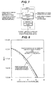
- Fig. 8 is a graph showing a result of computer simulation of the transmission performances in the first embodiment.
- the horizontal axis represents average received E s /N 0 and the vertical axis represents BER (Bit Error Rate).
- E s is energy per symbol and No is a noise spectrum density.
- the characteristics when MU-MIMO is performed between single-carriers (SC) agree with the characteristics of SC in MU-MIMO in which OFDM and SC exist mixedly. From this fact, it can be known that separation can be performed by multiplying the MMSE weights altogether regardless of the transmission scheme of each user.
- each transmitter determines the transmission scheme regardless of the transmission scheme of another transmitter. For example, even when a certain user performs single-carrier transmission, it is possible for another user to use multi-carrier transmission with high spectral efficiency at the same time and at the same frequency. Alternatively, even when a certain user performs multi-carrier transmission, it is possible for another user to use single-carrier transmission with less restriction on the allowable transmit power at the same time and at the same frequency. As described above, it is possible to dramatically increase the cell throughput by turning a multiuser MIMO system into a system in which the mixed existence of single-carrier transmissions and multi-carrier transmissions is allowed.
Abstract
Description
- The present invention relates to a multiuser MIMO system in which a plurality of transmitters performs transmission to at least one receiver, and relates to a receiver and a transmitter used in the system.
- In the next generation mobile communication, a high-speed data transmission is demanded. In order to perform a high-speed data transmission, a wide frequency band is necessary. However, in a radio communication channel, frequency selective fading including a number of delayed waves (multi-paths) occurs. When performing a wideband single-carrier transmission in such a communication environment, the sampling intervals of received signals become shorter, and therefore, the delayed wave in the channel causes inter-symbol interference, resulting in considerable deterioration in the transmission performances. There is a technique to suppress the inter-symbol interference by time domain signal processing, however, there is such a problem that the circuit scale of a receiver becomes very large.
- Hence, a multi-carrier transmission attracts attention, such as orthogonal frequency division multiplexing (OFDM) in which a large amount of data is transmitted in parallel in a frequency domain using a number of narrowband subcarriers arranged at orthogonal frequency intervals and multi-carrier code division multiple access (MC-CDMA).
- In the multi-carrier transmission, the periodicity of the OFDM symbol can be maintained by adding a waveform at the rear of an OFDM symbol interval to the front as a guard interval (GI). Hence, it is possible to perform signal processing that does not depend on the number of paths while each subcarrier maintains orthogonality between subcarriers without being affected by the multi-path even in the frequency selective fading environment. Hence, in LTE (Long Term Evolution) that is conformal with the standard of 3GPP (3rd Generation Partnership Project), OFDM is employed in a downlink (transmission from a base station to a mobile terminal). Further, OFDM is also used in terrestrial digital broadcasting, wireless LAN (Local Area Network), etc.
- On the other hand, in an uplink (transmission from a mobile terminal to a base station) in mobile communication, it is difficult to use the OFDM transmission with a high PAPR (Peak to Average Power Ratio) because of the problem of nonlinearity of a transmit power amplifier of a mobile terminal and it is desired to use a single-carrier transmission. Thus, in the uplink of LTE, a single-carrier transmission called SC-FDMA (Single Carrier Frequency Division Multiple Access (also called DFT-S-OFDM)) is employed. In SC-FDMA, it is possible to achieve excellent transmission performances with a frequency diversity effect obtained while suppressing inter-symbol interference by adding GI to a single-carrier transmission and using equalization to compensate for the distortion of a signal by one-time multiplication in the frequency domain (frequency domain equalization) based on the same concept as that of OFDM. As described above, in the present situation of the recent mobile communication, different transmission schemes are employed in the uplink and downlink.
- However, in the single-carrier transmission using frequency domain equalization, the inter-symbol interference cannot be suppressed completely, and therefore, there is such a problem that the transmission performances are somewhat deteriorated compared to those in the multi-carrier transmission (for example, OFDM). Further, in the single-carrier transmission, adaptive modulation on the frequency domain cannot be performed, and therefore, the throughput (spectral efficiency) is lowered compared to the multi-carrier transmission.
- Because of such a problem,
Patent Document 1 proposes the transmitter, receiver, mobile communication system, and transmission control method capable of switching between the single-carrier type radio access system and the multi-carrier type radio access system. InPatent Document 1, a switching part to switch the transmission schemes is provided in the transmitter. The switching part selects the single-carrier transmission when the required transmit power is high and the multi-carrier transmission with a high PAPR cannot be performed. On the other hand, the transmitter which has the low transmit power and for which PAPR is not problematic selects the multi-carrier transmission. This can improve the throughput of the entire cell. - As described above, it has also been proposed to cause mobile terminals that use different transmission schemes to exist in the uplink as well as using different transmission schemes in the uplink and downlink and the proposal is now actively discussed in 3GPP (Non-patent Document 1).
- Patent Document 1: Japanese Unexamined Patent Publication No.
2007-151059 - Non-patent Document 1:
R1-082575 - In
Patent Document 1, the single-carrier user and the multi-carrier user are time-division-multiplexed or frequency-division-multiplexed. However, in order to further realize higher speed data transmission in the entire system, it is preferable to improve throughput by applying the multiuser MIMO (Multiple Input Multiple Output) in which a plurality of users transmits at the same time and at the same frequency and the base station separates the signal of each user. On the other hand, conventionally, there is not such a system in which different transmission schemes are employed in the uplink, and therefore, it has been discussed that all the users perform the single-carrier (or multi-carrier) transmission in the multiuser MIMO. - However, the concept of the multiuser MIMO in the environment, in which each user uses different transmission schemes at the same time and at the same frequency, that is, the single-carrier and the multi-carrier exist mixedly, does not exist conventionally as a system. That is, conventionally, in a band in which a certain user performs the single-carrier transmission, it is required for another user to perform the single-carrier transmission even in the environment in which the user could perform the multi-carrier transmission. On the other hand, in a band in which a certain user already performs the multi-carrier transmission, although it is required for another user to perform the multi-carrier transmission, however if the environment does not allow the multi-carrier transmission to be performed, the user has nothing to do but give up the communication itself in that band.
- The present invention has been made in view of such circumstances and has an object to provide a multiuser MIMO system, a receiver, and a transmitter in which signals of each transmitter can be separated even when each transmitter uses different transmission schemes.
- (1) In order to achieve the above-mentioned object, the present invention took measures as described below. That is, the multiuser MIMO system of the present invention is a multiuser MIMO system in which a plurality of transmitters performs transmission to at least one receiver, characterized by including a plurality of transmitters for performing radio transmission in different transmission schemes and at least one receiver for receiving a signal radio-transmitted from each of the transmitters and separating the received signal for each of the transmitters to obtain data.
- As described above, a plurality of transmitters performs radio transmission in different transmission schemes and at least one receiver receives a signal radio-transmitted from each transmitter and acquires data by separating the received signal for each transmitter, and therefore, it is possible to provide a radio communication system in which a receiver can separate a signal even in an environment in which transmitters that perform radio transmission in different transmission schemes exist mixedly. Hence, it is possible for each transmitter to determine a transmission scheme regardless of the transmission scheme of another transmitter. As a result, it is made possible to improve the cell throughput.
- (2) Further, the multiuser MIMO system of the present invention is characterized in that the transmitter performs multiplexing only in partial frequency band in the system band and the receiver performs demultiplexing of a signal multiplexed only in the partial frequency band in the system band.
- As described above, the transmitter performs multiplexing only in the partial frequency band in the system band, and therefore, it is made possible to perform more flexible frequency scheduling. Further, in a frequency band in which the band used by a plurality of transmitters is not multiplexed or in a frequency band in which the number of multiplexed signals is smaller than the number of receive antennas, the receive antenna diversity effect can be obtained, and therefore, it is made possible to make an attempt to improve the transmission performances.
- (3) The receiver of the present invention is a receiver applied to a multiuser MIMO system in which a plurality of transmitters performs transmission to at least one receiver, and the receiver is characterized by including a reception part for receiving signals transmitted in different transmission schemes at the same time and at the same frequency; a MIMO separation part for separating the received signal for each of the transmitters; a switching part for switching output destinations according to the transmission scheme of the separated signal; and a signal processing part provided for each transmission scheme, for processing a signal output from the switching part according to its transmission scheme.
- As described above, the signals transmitted at the same time and at the same frequency in different transmission schemes are separated for each transmitter, the output destinations are switched according to the transmission scheme of the separated signal, and the processing according to the transmission scheme is performed, and therefore, it is possible to provide a radio communication system in which a receiver can separate a signal even in an environment in which transmitters that perform radio transmission in different transmission schemes exist mixedly. Hence, it is possible for each transmitter to determine a transmission scheme regardless of the transmission scheme of another transmitter. As a result, it is made possible to improve the cell throughput.
- (4) Further, the receiver of the present invention is characterized in that the MIMO separation part separates signals using an MMSE (Minimum Mean Square Error) weight.
- As described above, the MMSE weight is used, and therefore, it is made possible to separate a signal regardless of the transmission scheme of each transmitter.
- (5) Further, the receiver of the present invention is characterized in that the MIMO separation part demultiplexes a signal multiplexed only in partial frequency band in the system band using the MMSE weight.
- As described above, the receiver demultiplexes a signal multiplexed only in the partial frequency band in the system band using the MMSE weight, and therefore, it is possible for the transmitter to perform multiplexing only in the partial frequency band in the system band and it is made possible to perform more flexible frequency scheduling. Further, in a frequency band in which the band used by a plurality of transmitters is not multiplexed or in a frequency band in which the number of multiplexed signals is smaller than the number of receive antennas, the receive antenna diversity effect can be obtained, and therefore, it is made possible to make an attempt to improve the transmission performances.
- (6) The transmitter of the present invention is a transmitter applied to a multiuser MIMO system in which a plurality of transmitters performs transmission to at least one receiver, and the transmitter is characterized by transmitting a radio signal to the receiver according to any of claims 3 to 5 at the same time and at the same frequency as those of another transmitter in a transmission scheme different from that of the another transmitter.
- As described above, the transmitter transmits a radio signal to the receiver according to any of claims 3 to 5 at the same time and at the same frequency as those of another transmitter in a transmission scheme different from that of the another transmitter, and therefore, it is possible to provide a radio communication system in which a receiver can separate a signal even in an environment in which transmitters that perform radio transmission in different transmission schemes exist mixedly.
- According to the present invention, a plurality of transmitters performs radio transmission in different transmission schemes and at least one receiver receives a signal radio-transmitted from each transmitter and acquires data by separating the received signal for each transmitter, and therefore, it is possible to provide a radio communication system in which a receiver can separate a signal even in an environment in which transmitters that perform radio transmission in different transmission schemes exist mixedly. Hence, it is possible for each transmitter to determine a transmission scheme regardless of the transmission scheme of another transmitter. As a result, it is made possible to improve the cell throughput.
-
-
Fig. 1 is a diagram showing a schematic configuration of a transmitter that performs single-carrier transmission. -
Fig. 2 is a diagram showing a schematic configuration of a transmitter that performs OFDM transmission. -
Fig. 3 is a diagram showing a schematic configuration of a receiver having Nr receive antennas in a base station. -
Fig. 4 is a diagram showing a schematic configuration of a signal processing part. -
Fig. 5 is a diagram showing a schematic configuration of a single-carrier processing part. -
Fig. 6 is a diagram showing a schematic configuration of a multi-carrier processing part. -
Fig. 7 is a diagram showing a schematic configuration of a MIMO separation part. -
Fig. 8 is a graph showing a result of computer simulation of the transmission performances in a first embodiment. -
Fig. 9 is a diagram showing a schematic diagram of a transmitter that performs Clustered DFT-S-OFDM transmission. -
Fig. 10 is a diagram showing a configuration of a transmitter that performs OFDM transmission. -
Fig. 11 is a diagram showing the way the spectra of Clustered DFT-S-OFDM and OFDM are multiplexed. -
Fig. 12 is a diagram showing a configuration of a MIMO separation part according to a second embodiment. -
- 10
- error correction encoding part
- 11
- interleaving part
- 12
- modulation part
- 13
- GI addition part
- 14
- frame configuration part
- 15
- reference signal generation part
- 16
- radio transmission part
- 17
- antenna part
- 20
- IFFT part
- 30-1 to 30-Nr
- antenna part
- 31-1 to 31-Nr
- radio reception part
- 32-1 to 32-Nr
- reference signal separation part
- 33-1 to 33-Nr
- GI removal part
- 34-1 to 34-Nr
- FFT part
- 35
- signal processing part
- 36
- channel estimation part
- 40
- MIMO separation part
- 41
- switching part
- 42
- single-carrier processing part
- 43
- multi-carrier processing part
- 50
- IFFT part
- 51
- demodulation part
- 52
- deinterleaving part
- 53
- error correction decoding part
- 60
- P/S conversion part
- 70
- weight generation part
- 71
- weight multiplication part
- 90
- DFT part
- 91
- spectrum mapping part
- 92
- IFFT part
- 100
- P/S conversion part
- 120
- MIMO separation part
- 121
- zero replacing part
- 122
- transmission spectrum information part
- 123
- weight generation part
- 124
- weight multiplication part
- 125
- spectrum demapping part
- Next, embodiments according to the present invention will be described with reference to the drawings. In a first embodiment, an environment is supposed, in which each transmitter performs single-carrier transmission or multi-carrier transmission, and therefore, signals received by a receiver include single-carriers and multi-carriers mixedly in a multiuser MIMO system in which a plurality of transmitters accesses a base station at the same time and at the same frequency. The present invention realizes a communication system in which a signal of each user can be demultiplexed even in the environment described above.
-
Fig.1 is a diagram showing a schematic configuration of a transmitter that performs single-carrier transmission. The single-carrier transmission includes various types, however, in this specification, the single-carrier transmission is defined as a transmission scheme in which a single is generated in a time domain and the multi-carrier transmission as a transmission scheme in which a signal is generated in a frequency domain. Consequently, in the first embodiment, a pure single-carrier transmission is explained as an example of a single-carrier transmission, however, the first embodiment can also be applied to other single-carrier based transmission methods, such as DS-CDMA (Direct Sequence Code Division Multiple Access), DFT-S-OFDM (Discrete Fourier Transform Spread OFDM, also called SC-FDMA) employed in the uplink in LTE (Long Term Evolution) of 3GPP (3rd Generation Partnership Project), and Clustered DFT-S-OFDM being discussed in LTE-A (LTE Advanced) . - In
Fig. 1 , information data, that is a data bit sequence, is input to an errorcorrection encoding part 10. The errorcorrection encoding part 10 performs error correction encoding on the input data bit sequence, such as convolution code, turbo code, and LDPC (Low Density Parity Check) code, and outputs the coded bit sequence obtained to aninterleaving part 11. Theinterleaving part 11 interleaves the order to randomize the influence on the channel and outputs it to amodulation part 12. The modulatingpart 12 generates NFFT modulation symbols, such as QPSK (Quaternary Phase Shift Keying) and 16QAM (Quadrature Amplitude Modulation) and outputs them to aGI addition part 13. TheGI addition part 13 performs processing to add rear NGI symbols of the signal of the NFFT symbols to the front of the input signal and outputs a signal sequence of the NFFT + NGI symbols. A data signal s (t) output from theGI addition part 13 at time t is input to aframe configuration part 14 where a frame is configured by multiplexing the data signal s(t) and a reference signal generated by a referencesignal generation part 15 and the frame is output to aradio transmission part 16. Theradio transmission part 16 performs processing on an input digital signal, such as D/A (Digital to Analog) conversion, up-conversion, and band pass filtering, and then transmits the signal from anantenna part 17. - Next, a configuration of a transmitter that performs OFDM transmission is explained. In the present embodiment, OFDM is explained as an example of multi-carrier transmission, however, the present embodiment can also be applied to other multi-carrier based transmission methods, such as MC-CDMA and VSF-OFCDM (Variable Spreading Factor Orthogonal Frequency and Code Division Multiplexing).
-
Fig. 2 is a diagram showing a schematic configuration of a transmitter that performs OFDM transmission. The configuration of an OFDM transmitter is configured by inserting an IFFT (Inverse Fast Fourier Transform)part 20 between themodulation part 12 and theGI addition part 13 in the configuration of the single-carrier transmitter shown inFig. 1 and other configurations are the same. TheIFFT part 20 performs processing to convert a modulation symbol into a time domain. - In the first embodiment, the example is explained, in which each transmitter includes one transmit antenna and transmits a transmission signal in one line, however, it may also be possible for one transmitter to include a plurality of antennas and transmit a plurality of transmission signals using a plurality of lines.
- Here, when a mobile terminal includes both a multi-carrier transmitter and a single-carrier transmitter, the transmission scheme is generally determined by the location of the mobile terminal. For example, when the mobile terminal is located near the base station and the required transmit power of the mobile terminal is low, it is possible to improve the spectral efficiency more by using the multi-carrier transmission. On the other hand, for example, when the mobile terminal is located distant from the base station and the required transmit power of the mobile terminal is low, it is made possible to establish communication by performing the single-carrier transmission with a high PAPR.
- A signal transmitted from each transmitter is received by the antenna part of a receiver of the base station via a channel.
Fig. 3 is a diagram showing a schematic configuration of a receiver having Nr receive antennas in the base station. If the number of transmitters that perform transmission is assumed to be U, a received signal r(t) (Nr × 1 vector) at the time t is expressed by the following formula. -

- Here,

- The signal r (t) received by antenna parts 30-1 to 30-Nr is input to radio reception parts 31-1 to 31-Nr. In the radio reception parts 31-1 to 31-Nr, down-conversion, filtering processing, and A/D (Analog to Digital) conversion are performed and then the signal is input to reference signal separation parts 32-1 to 32-Nr. The reference signal separation parts 32-1 to 32-Nr perform separation between the reference signal and data signal.
- The reference signal is input to a
channel estimation part 36 and the data signal is input to GI removal parts 33-1 to 33-Nr. In the GI removal parts 33-1 to 33-Nr, GI of the NGI symbols added in the transmitter is removed from the data signal of the NFFT + NGI symbols and the data signal is output to FFT parts 34-1 to 34-Nr. In the FFT parts 34-1 to 34-Nr, FFT is applied to the input signal to convert the signal into a frequency domain signal. This processing is performed for each of the antenna parts 30-1 to 30-Nr independently. - A frequency domain received signal vector R (k) (Nr × 1 vector) in a k-th subcarrier obtained by applying FFT to the time domain received signal expressed by formula (3), which is the output of the FFT parts 34-1 to 34-Nr, is expressed by the following formula.
-

- Here,

- In the
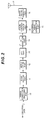
channel estimation part 36, an estimated value (expressed by formula (5)) of the channel matrix H (k) between each transmitter and each receive antenna expressed by formula (4) is found and estimation of average noise power σ2 in the receive antenna is made using the received reference signals in the number corresponding to the number of receive antennas and the results are output to asignal processing part 35. -

Fig. 4 is a diagram showing a schematic configuration of thesignal processing part 35. In thesignal processing part 35, input data signals of the frequency domain in the number corresponding to the number of receive antennas, the channel matrix estimation value, and the average noise power estimation value are input to aMIMO separation part 40. In theMIMO separation part 40, signal processing to separate data of each transmitter is performed using the channel matrix estimation value and the average noise power estimation value that are input and the frequency domain signals in the number corresponding to the separated U users (U transmitters) are output to a switchingpart 41. The schematic configuration of theMIMO separation part 40 will be described later. - In the switching
part 41, whether the frequency domain signals in the number corresponding to the separated U users are a signal transmitted by a single-carrier transmission or a signal transmitted by an OFDM transmission is determined and the output destinations of the input signal are switched according to the determination result. That is, the switchingpart 41 outputs the input signal to one of a single-carrier processing part 42 and amulti-carrier processing part 43. For example, when a user u performs a single-carrier transmission, the frequency domain signal of the user u output from theMIMO separation part 40 is output to the single-carrier processing part 42 by the switchingpart 41. On the other hand, when the user u performs an OFDM transmission, the frequency domain signal of the user u output from theMIMO separation part 40 is output to themulti-carrier processing part 43 by the switchingpart 41. -
Fig. 5 is a diagram showing a schematic configuration of the single-carrier processing part 42. As shown inFig. 5 , in the single-carrier processing part 42, the frequency domain signal of the separated u-th user is converted into a time domain by anIFFT part 50. Next, in ademodulation part 51, demodulation based on the modulation performed in the transmitter is performed. Further, in adeinterleaving part 52, processing to cancel the interleaving performed in the transmitter is performed and in an errorcorrection decoding part 53, error correction decoding processing is performed. Due to this, the data the u-th user has transmitted is obtained. -
Fig. 6 is a diagram showing a schematic configuration of themulti-carrier processing part 43. Themulti-carrier processing part 43 has the same configuration as that of the single-carrier processing part 42 shown inFig. 5 except in that a P/S conversion part 60 is provided instead of theIFFT part 50. -
Fig. 7 is a diagram showing a schematic configuration of theMIMO separation part 40. The estimated value of the estimated value of the channel matrix (expressed by formula (5)) input from thechannel estimation part 36 and the noise power estimation value σ2 are input to aweight generation part 70. In theweight generation part 70, weights, such as an MMSE (Minimum Mean Square Error) weight and a ZF (Zero Forcing) weight, are calculated. For example, an MMSE weight matrix w (k) (U × Nr matrix) is expressed by the following formula. -

- The obtained weight is input to a
weight multiplication part 71. In theweight multiplication part 71, MIMO separation is performed by multiplying the weight matrix w (k) (U × Nr matrix) and the vector R (k) (Nr × 1 vector). The frequency domain signal vector (U × 1 vector) of each user after separation is expressed by the following formula. -

weight multiplication part 71 outputs the frequency domain signal of each user after separation for U users. TheMIMO separation part 40 in the first embodiment has a configuration in which MIMO separation is performed by multiplying the MMSE weights altogether regardless of the transmission scheme of each user when the single-carrier signal and the OFDM signal exist mixedly in the receive antenna. -
Fig. 8 is a graph showing a result of computer simulation of the transmission performances in the first embodiment. InFig. 8 , the horizontal axis represents average received Es/N0 and the vertical axis represents BER (Bit Error Rate). Here, Es is energy per symbol and No is a noise spectrum density. As shown inFig. 8 , the characteristics when MU-MIMO is performed between single-carriers (SC) agree with the characteristics of SC in MU-MIMO in which OFDM and SC exist mixedly. From this fact, it can be known that separation can be performed by multiplying the MMSE weights altogether regardless of the transmission scheme of each user. - In the first embodiment, as the MIMO separation method, space filtering in which a weight is multiplied for each antenna and antenna combining is performed is used, however, other separation methods, such as MLD (Maximum Likelihood Detection), may be used.
- Conventionally, it is necessary for a transmitter to achieve multiuser MIMO by performing transmission in the same transmission scheme as that of another transmitter, however, according to the first embodiment, it is possible for each transmitter to determine the transmission scheme regardless of the transmission scheme of another transmitter. For example, even when a certain user performs single-carrier transmission, it is possible for another user to use multi-carrier transmission with high spectral efficiency at the same time and at the same frequency. Alternatively, even when a certain user performs multi-carrier transmission, it is possible for another user to use single-carrier transmission with less restriction on the allowable transmit power at the same time and at the same frequency. As described above, it is possible to dramatically increase the cell throughput by turning a multiuser MIMO system into a system in which the mixed existence of single-carrier transmissions and multi-carrier transmissions is allowed.
- In the above-described first embodiment, the case where all of the spectra of respective users overlap is explained, however, in a second embodiment, a case is explained, where MIMO multiplexing is performed only in a certain partial spectrum. Further, in the second embodiment, explanation is given using Clustered DFT-S-OFDM as single-carrier transmission and OFDM that uses a discontinuous band as multi-carrier transmission, however, the present invention can be embodied also when other systems are used.
-
Fig. 9 is a diagram showing a schematic configuration of a transmitter that performs Clustered DFT-S-OFDM transmission. The configuration differs from that of the transmitter that performs single-carrier transmission shown inFig. 1 only in that aDFT part 90, aspectrum mapping part 91, and anIFFT part 92 are inserted between themodulation part 12 and theGI addition part 13. - The output of the
modulation part 12 is input to theDFT part 90. TheDFT part 90 applies NDFT-point DFT to NDFT modulation symbols to convert them into frequency domain signals. The obtained NDFT-point frequency spectra are output to thespectrum mapping part 91. Thespectrum mapping part 91 divides the input NDFT-point frequency spectra into clusters (cluster is a set of one or more spectra) and allocates each cluster to any of the NFFT frequency points. Allocation methods include various methods, such as one in which the cluster is allocated to an arbitrary frequency in an excellent channel state and a method in which the cluster is allocated to a frequency not used by any transmitter. Thespectrum mapping part 91 inserts zero into a frequency to which no cluster is allocated and outputs it to theIFFT part 92. - The
IFFT part 92 applies NFFT-point IFFT to the frequency domain signals after the allocation obtained by thespectrum mapping part 91 and converts them into time domain signals of NFFT symbols. The output of theIFFT part 92 is input to theGI addition part 13. The subsequent processing is the same as that in the case of the first embodiment shown inFig. 1 . -
Fig. 10 is a diagram showing a configuration of a transmitter that performs OFDM transmission. The configuration of this transmitter differs from that of the transmitter that performs Clustered DFT-S-OFDM transmission shown inFig. 9 only in that a S/P conversion part 100 is provided instead of theDFT part 90. The S/P conversion part 100 performs Serial-to-parallel conversion on a signal input from themodulation part 12 and outputs it to thespectrum mapping part 91. The subsequent processing is the same as that of the transmitter that performs Clustered DFT-S-OFDM transmission shown inFig. 9 . -
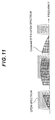
Fig. 11 is a diagram showing the way the spectra of Clustered DFT-S-OFDM and OFDM are multiplexed. In the second embodiment, as shown inFig. 11 , the spectra of Clustered DFT-S-OFDM and OFDM are multiplexed and received only in a partial frequency band in the receive antenna. - The configuration of a receiver according to the second embodiment is explained. The processing from the reception of a signal to the inputting of the signal to the MIMO separation part is the same as that of the receiver according to the first embodiment shown in
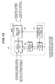
Fig. 3 to Fig. 7 .Fig. 12 is a diagram showing the configuration of the MIMO separation part according to the second embodiment. In aMIMO separation part 120, the channel matrix estimation value and the average noise power estimation value input from thechannel estimation part 36 are input to a zero replacingpart 121. In the zero replacingpart 121, based on information about the frequency used by each user notified from a transmissionspectrum information part 122, the value of a channel in which no data transmission is performed among the elements of the channel matrix of each subcarrier expressed by formula (4) is set to zero and the channel matrix estimation value for which zero replacement is performed and the average noise power estimation value are output to aweight generation part 123. In theweight generation part 123, weights are calculated, such as the MMSE weight and the ZF weight. For example, the MMSE weight w (k) (U × Nr matrix) is calculated based on formula (6). - The obtained weight is output to a
weight multiplication part 124. In theweight multiplication part 124, the frequency domain received signal of each antenna is input to theweight multiplication part 124 and multiplied by the weight. As a result, the frequency domain signal separated for each user is obtained. The frequency domain signal of each user is input to aspectrum demapping part 125. In thespectrum demapping part 125, based on information about the frequency used by each user from the transmissionspectrum information part 122, processing to extract the transmission spectrum of each user is performed. Thespectrum demapping part 125 outputs the frequency domain signal of each user. - After that, the frequency domain signal of each user is input to the switching
part 41 shown inFig. 4 as in the first embodiment and is input to the single-carrier processing part 42 or themulti-carrier processing part 43 depending on whether the signal is transmitted by a single-carrier transmission or a multi-carrier transmission. - As described above, it is possible to perform more flexible frequency scheduling by allowing users who perform multiuser MIMO to multiplex partially instead of sharing all the bands in which transmission is performed. Further, in a frequency in which any user is not multiplexed or the number of multiplexed signals is smaller than the number of receive antennas, the receive antenna diversity effect can also be obtained, and therefore, it is possible to achieve excellent transmission performances. As a result of the above, it is possible to considerably improve the cell throughput.
Claims (6)
- A multiuser MIMO (Multiple Input Multiple Output) system in which a plurality of transmitters performs transmission to at least one receiver, the system comprising:a plurality of transmitters for performing radio transmission in different transmission schemes; andat least one receiver for receiving a signal radio-transmitted from each of said transmitters and separating said received signal for each of said transmitters to obtain data.
- The multiuser MIMO system according to claim 1, wherein
said transmitter performs multiplexing only in partial frequency band in a system band, and
said receiver demultiplexes a signal multiplexed only in partial frequency band in said system band. - A receiver that is applied to a multiuser MIMO system in which a plurality of transmitters performs transmission to at least one receiver, the receiver comprising:a reception part (31-1 ··· 31-Nr) for receiving signals transmitted in different transmission schemes at the same time and at the same frequency;a MIMO separation part (40) for separating said received signal for each of said transmitters;a switching part (41) for switching output destinations according to the transmission scheme of said separated signal; anda signal processing part (35) provided for each transmission scheme, for processing a signal output from said switching part according to its transmission scheme.
- The receiver according to claim 3, wherein
said MIMO separation part (40) separates a signal using an MMSE (Minimum Mean Square Error) weight. - The receiver according to claim 4, wherein
said MIMO separation part (40) demultiplexes a signal multiplexed only in partial frequency band in a system band using the MMSE weight. - A transmitter that is applied to a multiuser MIMO system in which a plurality of transmitters performs transmission to at least one receiver, wherein
the transmitter transmits a radio signal to a receiver according to any of claim 3 to claim 5 at the same time and at the same frequency as those of another transmitter in a transmission scheme different from that of said another transmitter.
Applications Claiming Priority (2)
| Application Number | Priority Date | Filing Date | Title |
|---|---|---|---|
| JP2008278544 | 2008-10-29 | ||
| PCT/JP2009/068073 WO2010050384A1 (en) | 2008-10-29 | 2009-10-20 | Multi-user mimo system, receiver apparatus and transmitter apparatus |
Publications (3)
| Publication Number | Publication Date |
|---|---|
| EP2352246A1 true EP2352246A1 (en) | 2011-08-03 |
| EP2352246A4 EP2352246A4 (en) | 2014-07-02 |
| EP2352246B1 EP2352246B1 (en) | 2019-07-17 |
Family
ID=42128749
Family Applications (1)
| Application Number | Title | Priority Date | Filing Date |
|---|---|---|---|
| EP09823496.6A Active EP2352246B1 (en) | 2008-10-29 | 2009-10-20 | Multi-user mimo system, receiver apparatus and transmitter apparatus |
Country Status (7)
| Country | Link |
|---|---|
| US (1) | US8824600B2 (en) |
| EP (1) | EP2352246B1 (en) |
| JP (1) | JP5547648B2 (en) |
| KR (1) | KR20110079755A (en) |
| CN (2) | CN107317612B (en) |
| WO (1) | WO2010050384A1 (en) |
| ZA (1) | ZA201103783B (en) |
Families Citing this family (6)
| Publication number | Priority date | Publication date | Assignee | Title |
|---|---|---|---|---|
| WO2009022709A1 (en) * | 2007-08-13 | 2009-02-19 | Sharp Kabushiki Kaisha | Radio communication system, radio communication method, radio communication device, reception device, and program |
| WO2009110547A1 (en) | 2008-03-05 | 2009-09-11 | シャープ株式会社 | Communication system, communication device and communication method |
| CN107104756B (en) | 2011-02-08 | 2020-06-12 | 日本电信电话株式会社 | Receiving apparatus and receiving method |
| US20170109233A1 (en) * | 2015-10-20 | 2017-04-20 | Sandisk Technologies Inc. | Data encoding using an adjoint matrix |
| US10326558B2 (en) * | 2016-07-20 | 2019-06-18 | Intel Corporation | Apparatus, system and method of communicating a single carrier (SC) transmission |
| JP7052795B2 (en) * | 2017-07-25 | 2022-04-12 | 日本電気株式会社 | Wireless communication devices, methods, programs, computer-readable non-temporary recording media, and systems |
Citations (2)
| Publication number | Priority date | Publication date | Assignee | Title |
|---|---|---|---|---|
| US20080096574A1 (en) * | 2006-09-11 | 2008-04-24 | Aamod Khandekar | Dyanmic power amplifier backoff |
| WO2008057969A2 (en) * | 2006-11-01 | 2008-05-15 | Qualcomm Incorporated | Joint use of multi-carrier and single-carrier multiplexing schemes for wireless communication |
Family Cites Families (14)
| Publication number | Priority date | Publication date | Assignee | Title |
|---|---|---|---|---|
| US7260369B2 (en) * | 2005-08-03 | 2007-08-21 | Kamilo Feher | Location finder, tracker, communication and remote control system |
| US20030125040A1 (en) * | 2001-11-06 | 2003-07-03 | Walton Jay R. | Multiple-access multiple-input multiple-output (MIMO) communication system |
| US8194703B2 (en) * | 2002-08-07 | 2012-06-05 | Kyocera Corporation | Wireless communication system |
| JP4592523B2 (en) * | 2004-07-29 | 2010-12-01 | パナソニック株式会社 | Wireless transmission device and wireless reception device |
| JP2006135674A (en) | 2004-11-05 | 2006-05-25 | Ntt Docomo Inc | Receiver for mobile communication, transmitter for mobile communication, reception method for mobile communication, and transmission method for mobile communication |
| JP4527067B2 (en) | 2005-03-31 | 2010-08-18 | 株式会社エヌ・ティ・ティ・ドコモ | Mobile station, transmission method, and mobile communication system |
| US9130791B2 (en) * | 2006-03-20 | 2015-09-08 | Qualcomm Incorporated | Uplink channel estimation using a signaling channel |
| US8457265B2 (en) * | 2007-08-23 | 2013-06-04 | Qualcomm Incorporated | Method and apparatus for generating coefficients in a multi-input-multi-output (MIMO) system |
| JP2009111620A (en) * | 2007-10-29 | 2009-05-21 | Kyocera Corp | Radio communication method and radio communication device |
| JP5206945B2 (en) * | 2007-12-17 | 2013-06-12 | 日本電気株式会社 | Multi-user MIMO scheduling method |
| KR101599844B1 (en) * | 2007-12-24 | 2016-03-04 | 엘지전자 주식회사 | Method of Multiplexing Multiple Access Region |
| US20090180459A1 (en) * | 2008-01-16 | 2009-07-16 | Orlik Philip V | OFDMA Frame Structures for Uplinks in MIMO Networks |
| JP4551933B2 (en) * | 2008-01-25 | 2010-09-29 | 日本電信電話株式会社 | Multiple channel spatial multiplexing transmission method and communication apparatus |
| US8867461B2 (en) * | 2008-08-11 | 2014-10-21 | Lg Electronics Inc. | Method of transmitting or receiving uplink signals and equipment therefor |
-
2009
- 2009-10-20 CN CN201710747652.5A patent/CN107317612B/en active Active
- 2009-10-20 WO PCT/JP2009/068073 patent/WO2010050384A1/en active Application Filing
- 2009-10-20 CN CN2009801435328A patent/CN102204139A/en active Pending
- 2009-10-20 EP EP09823496.6A patent/EP2352246B1/en active Active
- 2009-10-20 US US13/126,697 patent/US8824600B2/en active Active
- 2009-10-20 KR KR1020117011964A patent/KR20110079755A/en active Search and Examination
- 2009-10-20 JP JP2010535762A patent/JP5547648B2/en active Active
-
2011
- 2011-05-24 ZA ZA2011/03783A patent/ZA201103783B/en unknown
Patent Citations (2)
| Publication number | Priority date | Publication date | Assignee | Title |
|---|---|---|---|---|
| US20080096574A1 (en) * | 2006-09-11 | 2008-04-24 | Aamod Khandekar | Dyanmic power amplifier backoff |
| WO2008057969A2 (en) * | 2006-11-01 | 2008-05-15 | Qualcomm Incorporated | Joint use of multi-carrier and single-carrier multiplexing schemes for wireless communication |
Non-Patent Citations (1)
| Title |
|---|
| See also references of WO2010050384A1 * |
Also Published As
| Publication number | Publication date |
|---|---|
| EP2352246B1 (en) | 2019-07-17 |
| ZA201103783B (en) | 2012-07-25 |
| JPWO2010050384A1 (en) | 2012-03-29 |
| CN107317612B (en) | 2021-01-29 |
| CN102204139A (en) | 2011-09-28 |
| US20110255624A1 (en) | 2011-10-20 |
| US8824600B2 (en) | 2014-09-02 |
| WO2010050384A1 (en) | 2010-05-06 |
| EP2352246A4 (en) | 2014-07-02 |
| KR20110079755A (en) | 2011-07-07 |
| JP5547648B2 (en) | 2014-07-16 |
| CN107317612A (en) | 2017-11-03 |
Similar Documents
| Publication | Publication Date | Title |
|---|---|---|
| EP2530844B1 (en) | Hybrid orthogonal frequency division multiple access system and method | |
| KR101766489B1 (en) | Communication device and communication method | |
| KR101567078B1 (en) | Apparatus and method for data transmission using multiple antenna | |
| KR101507170B1 (en) | Apparatus and method for data transmission using transmit diversity in sc-fdma system | |
| KR101497154B1 (en) | Apparatus and method for data transmission using transmit diversity in sc-fdma system | |
| KR101440628B1 (en) | Apparatus and method for data transmission using transmit diversity in sc-fdma system | |
| EP1832074B1 (en) | Method and apparatus for transmitting/receiving a signal in an FFH-OFDM communication system | |
| KR101534349B1 (en) | Method for data transmission using space time block code | |
| US9008166B2 (en) | Filter calculating device, transmitting device, receiving device, processor, and filter calculating method | |
| KR101467586B1 (en) | Apparatus and method for data transmission using transmit diversity in wireless system | |
| EP2352246B1 (en) | Multi-user mimo system, receiver apparatus and transmitter apparatus | |
| CN103780528A (en) | Communication system and signal sending method and apparatus as well as signal receiving method and apparatus thereof | |
| WO2011122618A1 (en) | Wireless communication system and receiver apparatus | |
| WO2011129403A1 (en) | Wireless communication system, wireless communication apparatus, program and transmission method | |
| EP2293615A1 (en) | Relay device, communication system, and relay method | |
| Khan et al. | Beamforming for rejection of co-channels interference in an OFDM system | |
| CN103780529A (en) | Communication system and signal sending method and apparatus as well as signal receiving method and apparatus thereof | |
| CN102812737B (en) | There is the X-MIMO system of multiple emitter and multiple collector |
Legal Events
| Date | Code | Title | Description |
|---|---|---|---|
| PUAI | Public reference made under article 153(3) epc to a published international application that has entered the european phase |
Free format text: ORIGINAL CODE: 0009012 |
|
| 17P | Request for examination filed |
Effective date: 20110526 |
|
| AK | Designated contracting states |
Kind code of ref document: A1 Designated state(s): AT BE BG CH CY CZ DE DK EE ES FI FR GB GR HR HU IE IS IT LI LT LU LV MC MK MT NL NO PL PT RO SE SI SK SM TR |
|
| DAX | Request for extension of the european patent (deleted) | ||
| A4 | Supplementary search report drawn up and despatched |
Effective date: 20140530 |
|
| RIC1 | Information provided on ipc code assigned before grant |
Ipc: H04L 25/02 20060101ALI20140523BHEP Ipc: H04L 27/26 20060101ALI20140523BHEP Ipc: H04W 72/00 20090101ALN20140523BHEP Ipc: H04B 7/04 20060101AFI20140523BHEP Ipc: H04J 11/00 20060101ALI20140523BHEP |
|
| 17Q | First examination report despatched |
Effective date: 20160122 |
|
| STAA | Information on the status of an ep patent application or granted ep patent |
Free format text: STATUS: EXAMINATION IS IN PROGRESS |
|
| REG | Reference to a national code |
Ref country code: DE Ref legal event code: R079 Ref document number: 602009059171 Country of ref document: DE Free format text: PREVIOUS MAIN CLASS: H04J0099000000 Ipc: H04B0007040000 |
|
| GRAP | Despatch of communication of intention to grant a patent |
Free format text: ORIGINAL CODE: EPIDOSNIGR1 |
|
| STAA | Information on the status of an ep patent application or granted ep patent |
Free format text: STATUS: GRANT OF PATENT IS INTENDED |
|
| RIC1 | Information provided on ipc code assigned before grant |
Ipc: H04J 11/00 20060101ALI20181130BHEP Ipc: H04L 27/26 20060101ALI20181130BHEP Ipc: H04B 7/04 20170101AFI20181130BHEP Ipc: H04L 25/02 20060101ALI20181130BHEP Ipc: H04W 72/00 20090101ALN20181130BHEP |
|
| INTG | Intention to grant announced |
Effective date: 20190104 |
|
| GRAS | Grant fee paid |
Free format text: ORIGINAL CODE: EPIDOSNIGR3 |
|
| RAP1 | Party data changed (applicant data changed or rights of an application transferred) |
Owner name: SHARP KABUSHIKI KAISHA |
|
| RIN1 | Information on inventor provided before grant (corrected) |
Inventor name: URABE, SHUUJI C/O SHARP KABUSHIKI KAISHA Inventor name: TAKAHASHI, HIROKI C/O SHARP KABUSHIKI KAISHA Inventor name: HAMAGUCHI, YASUHIRO C/O SHARP KABUSHIKI KAISHA Inventor name: YOKOMAKURA, KAZUNARI C/O SHARP KABUSHIKI KAISHA Inventor name: NAKAMURA, OSAMU C/O SHARP KABUSHIKI KAISHA Inventor name: GOTO, JUNGO C/O SHARP KABUSHIKI KAISHA |
|
| GRAA | (expected) grant |
Free format text: ORIGINAL CODE: 0009210 |
|
| STAA | Information on the status of an ep patent application or granted ep patent |
Free format text: STATUS: THE PATENT HAS BEEN GRANTED |
|
| AK | Designated contracting states |
Kind code of ref document: B1 Designated state(s): AT BE BG CH CY CZ DE DK EE ES FI FR GB GR HR HU IE IS IT LI LT LU LV MC MK MT NL NO PL PT RO SE SI SK SM TR |
|
| REG | Reference to a national code |
Ref country code: GB Ref legal event code: FG4D |
|
| REG | Reference to a national code |
Ref country code: CH Ref legal event code: EP |
|
| REG | Reference to a national code |
Ref country code: IE Ref legal event code: FG4D |
|
| REG | Reference to a national code |
Ref country code: DE Ref legal event code: R096 Ref document number: 602009059171 Country of ref document: DE |
|
| REG | Reference to a national code |
Ref country code: AT Ref legal event code: REF Ref document number: 1156775 Country of ref document: AT Kind code of ref document: T Effective date: 20190815 |
|
| REG | Reference to a national code |
Ref country code: NL Ref legal event code: MP Effective date: 20190717 |
|
| REG | Reference to a national code |
Ref country code: LT Ref legal event code: MG4D |
|
| REG | Reference to a national code |
Ref country code: AT Ref legal event code: MK05 Ref document number: 1156775 Country of ref document: AT Kind code of ref document: T Effective date: 20190717 |
|
| PG25 | Lapsed in a contracting state [announced via postgrant information from national office to epo] |
Ref country code: FI Free format text: LAPSE BECAUSE OF FAILURE TO SUBMIT A TRANSLATION OF THE DESCRIPTION OR TO PAY THE FEE WITHIN THE PRESCRIBED TIME-LIMIT Effective date: 20190717 Ref country code: LT Free format text: LAPSE BECAUSE OF FAILURE TO SUBMIT A TRANSLATION OF THE DESCRIPTION OR TO PAY THE FEE WITHIN THE PRESCRIBED TIME-LIMIT Effective date: 20190717 Ref country code: SE Free format text: LAPSE BECAUSE OF FAILURE TO SUBMIT A TRANSLATION OF THE DESCRIPTION OR TO PAY THE FEE WITHIN THE PRESCRIBED TIME-LIMIT Effective date: 20190717 Ref country code: HR Free format text: LAPSE BECAUSE OF FAILURE TO SUBMIT A TRANSLATION OF THE DESCRIPTION OR TO PAY THE FEE WITHIN THE PRESCRIBED TIME-LIMIT Effective date: 20190717 Ref country code: AT Free format text: LAPSE BECAUSE OF FAILURE TO SUBMIT A TRANSLATION OF THE DESCRIPTION OR TO PAY THE FEE WITHIN THE PRESCRIBED TIME-LIMIT Effective date: 20190717 Ref country code: NL Free format text: LAPSE BECAUSE OF FAILURE TO SUBMIT A TRANSLATION OF THE DESCRIPTION OR TO PAY THE FEE WITHIN THE PRESCRIBED TIME-LIMIT Effective date: 20190717 Ref country code: PT Free format text: LAPSE BECAUSE OF FAILURE TO SUBMIT A TRANSLATION OF THE DESCRIPTION OR TO PAY THE FEE WITHIN THE PRESCRIBED TIME-LIMIT Effective date: 20191118 Ref country code: BG Free format text: LAPSE BECAUSE OF FAILURE TO SUBMIT A TRANSLATION OF THE DESCRIPTION OR TO PAY THE FEE WITHIN THE PRESCRIBED TIME-LIMIT Effective date: 20191017 Ref country code: NO Free format text: LAPSE BECAUSE OF FAILURE TO SUBMIT A TRANSLATION OF THE DESCRIPTION OR TO PAY THE FEE WITHIN THE PRESCRIBED TIME-LIMIT Effective date: 20191017 |
|
| PG25 | Lapsed in a contracting state [announced via postgrant information from national office to epo] |
Ref country code: ES Free format text: LAPSE BECAUSE OF FAILURE TO SUBMIT A TRANSLATION OF THE DESCRIPTION OR TO PAY THE FEE WITHIN THE PRESCRIBED TIME-LIMIT Effective date: 20190717 Ref country code: LV Free format text: LAPSE BECAUSE OF FAILURE TO SUBMIT A TRANSLATION OF THE DESCRIPTION OR TO PAY THE FEE WITHIN THE PRESCRIBED TIME-LIMIT Effective date: 20190717 Ref country code: IS Free format text: LAPSE BECAUSE OF FAILURE TO SUBMIT A TRANSLATION OF THE DESCRIPTION OR TO PAY THE FEE WITHIN THE PRESCRIBED TIME-LIMIT Effective date: 20191117 Ref country code: GR Free format text: LAPSE BECAUSE OF FAILURE TO SUBMIT A TRANSLATION OF THE DESCRIPTION OR TO PAY THE FEE WITHIN THE PRESCRIBED TIME-LIMIT Effective date: 20191018 |
|
| PG25 | Lapsed in a contracting state [announced via postgrant information from national office to epo] |
Ref country code: TR Free format text: LAPSE BECAUSE OF FAILURE TO SUBMIT A TRANSLATION OF THE DESCRIPTION OR TO PAY THE FEE WITHIN THE PRESCRIBED TIME-LIMIT Effective date: 20190717 |
|
| PG25 | Lapsed in a contracting state [announced via postgrant information from national office to epo] |
Ref country code: PL Free format text: LAPSE BECAUSE OF FAILURE TO SUBMIT A TRANSLATION OF THE DESCRIPTION OR TO PAY THE FEE WITHIN THE PRESCRIBED TIME-LIMIT Effective date: 20190717 Ref country code: DK Free format text: LAPSE BECAUSE OF FAILURE TO SUBMIT A TRANSLATION OF THE DESCRIPTION OR TO PAY THE FEE WITHIN THE PRESCRIBED TIME-LIMIT Effective date: 20190717 Ref country code: EE Free format text: LAPSE BECAUSE OF FAILURE TO SUBMIT A TRANSLATION OF THE DESCRIPTION OR TO PAY THE FEE WITHIN THE PRESCRIBED TIME-LIMIT Effective date: 20190717 Ref country code: RO Free format text: LAPSE BECAUSE OF FAILURE TO SUBMIT A TRANSLATION OF THE DESCRIPTION OR TO PAY THE FEE WITHIN THE PRESCRIBED TIME-LIMIT Effective date: 20190717 Ref country code: IT Free format text: LAPSE BECAUSE OF FAILURE TO SUBMIT A TRANSLATION OF THE DESCRIPTION OR TO PAY THE FEE WITHIN THE PRESCRIBED TIME-LIMIT Effective date: 20190717 |
|
| PG25 | Lapsed in a contracting state [announced via postgrant information from national office to epo] |
Ref country code: SM Free format text: LAPSE BECAUSE OF FAILURE TO SUBMIT A TRANSLATION OF THE DESCRIPTION OR TO PAY THE FEE WITHIN THE PRESCRIBED TIME-LIMIT Effective date: 20190717 Ref country code: IS Free format text: LAPSE BECAUSE OF FAILURE TO SUBMIT A TRANSLATION OF THE DESCRIPTION OR TO PAY THE FEE WITHIN THE PRESCRIBED TIME-LIMIT Effective date: 20200224 Ref country code: SK Free format text: LAPSE BECAUSE OF FAILURE TO SUBMIT A TRANSLATION OF THE DESCRIPTION OR TO PAY THE FEE WITHIN THE PRESCRIBED TIME-LIMIT Effective date: 20190717 Ref country code: MC Free format text: LAPSE BECAUSE OF FAILURE TO SUBMIT A TRANSLATION OF THE DESCRIPTION OR TO PAY THE FEE WITHIN THE PRESCRIBED TIME-LIMIT Effective date: 20190717 Ref country code: CZ Free format text: LAPSE BECAUSE OF FAILURE TO SUBMIT A TRANSLATION OF THE DESCRIPTION OR TO PAY THE FEE WITHIN THE PRESCRIBED TIME-LIMIT Effective date: 20190717 |
|
| REG | Reference to a national code |
Ref country code: CH Ref legal event code: PL |
|
| REG | Reference to a national code |
Ref country code: DE Ref legal event code: R097 Ref document number: 602009059171 Country of ref document: DE |
|
| PLBE | No opposition filed within time limit |
Free format text: ORIGINAL CODE: 0009261 |
|
| STAA | Information on the status of an ep patent application or granted ep patent |
Free format text: STATUS: NO OPPOSITION FILED WITHIN TIME LIMIT |
|
| PG2D | Information on lapse in contracting state deleted |
Ref country code: IS |
|
| PG25 | Lapsed in a contracting state [announced via postgrant information from national office to epo] |
Ref country code: LU Free format text: LAPSE BECAUSE OF NON-PAYMENT OF DUE FEES Effective date: 20191020 Ref country code: CH Free format text: LAPSE BECAUSE OF NON-PAYMENT OF DUE FEES Effective date: 20191031 Ref country code: LI Free format text: LAPSE BECAUSE OF NON-PAYMENT OF DUE FEES Effective date: 20191031 |
|
| 26N | No opposition filed |
Effective date: 20200603 |
|
| REG | Reference to a national code |
Ref country code: BE Ref legal event code: MM Effective date: 20191031 |
|
| PG25 | Lapsed in a contracting state [announced via postgrant information from national office to epo] |
Ref country code: SI Free format text: LAPSE BECAUSE OF FAILURE TO SUBMIT A TRANSLATION OF THE DESCRIPTION OR TO PAY THE FEE WITHIN THE PRESCRIBED TIME-LIMIT Effective date: 20190717 Ref country code: BE Free format text: LAPSE BECAUSE OF NON-PAYMENT OF DUE FEES Effective date: 20191031 |
|
| PG25 | Lapsed in a contracting state [announced via postgrant information from national office to epo] |
Ref country code: IE Free format text: LAPSE BECAUSE OF NON-PAYMENT OF DUE FEES Effective date: 20191020 |
|
| PG25 | Lapsed in a contracting state [announced via postgrant information from national office to epo] |
Ref country code: CY Free format text: LAPSE BECAUSE OF FAILURE TO SUBMIT A TRANSLATION OF THE DESCRIPTION OR TO PAY THE FEE WITHIN THE PRESCRIBED TIME-LIMIT Effective date: 20190717 |
|
| PG25 | Lapsed in a contracting state [announced via postgrant information from national office to epo] |
Ref country code: HU Free format text: LAPSE BECAUSE OF FAILURE TO SUBMIT A TRANSLATION OF THE DESCRIPTION OR TO PAY THE FEE WITHIN THE PRESCRIBED TIME-LIMIT; INVALID AB INITIO Effective date: 20091020 Ref country code: MT Free format text: LAPSE BECAUSE OF FAILURE TO SUBMIT A TRANSLATION OF THE DESCRIPTION OR TO PAY THE FEE WITHIN THE PRESCRIBED TIME-LIMIT Effective date: 20190717 |
|
| REG | Reference to a national code |
Ref country code: DE Ref legal event code: R081 Ref document number: 602009059171 Country of ref document: DE Owner name: GUANGDONG OPPO MOBILE TELECOMMUNICATIONS CORP., CN Free format text: FORMER OWNER: SHARP KABUSHIKI KAISHA, SAKAI-CITY, OSAKA, JP |
|
| REG | Reference to a national code |
Ref country code: GB Ref legal event code: 732E Free format text: REGISTERED BETWEEN 20220421 AND 20220427 |
|
| PG25 | Lapsed in a contracting state [announced via postgrant information from national office to epo] |
Ref country code: MK Free format text: LAPSE BECAUSE OF FAILURE TO SUBMIT A TRANSLATION OF THE DESCRIPTION OR TO PAY THE FEE WITHIN THE PRESCRIBED TIME-LIMIT Effective date: 20190717 |
|
| PGFP | Annual fee paid to national office [announced via postgrant information from national office to epo] |
Ref country code: GB Payment date: 20231024 Year of fee payment: 15 |
|
| PGFP | Annual fee paid to national office [announced via postgrant information from national office to epo] |
Ref country code: FR Payment date: 20231020 Year of fee payment: 15 Ref country code: DE Payment date: 20231023 Year of fee payment: 15 |
|
| P01 | Opt-out of the competence of the unified patent court (upc) registered |
Effective date: 20240110 |