EP2352148A1 - Noise gate, sound collection device, and noise removal method - Google Patents
Noise gate, sound collection device, and noise removal method Download PDFInfo
- Publication number
- EP2352148A1 EP2352148A1 EP09827585A EP09827585A EP2352148A1 EP 2352148 A1 EP2352148 A1 EP 2352148A1 EP 09827585 A EP09827585 A EP 09827585A EP 09827585 A EP09827585 A EP 09827585A EP 2352148 A1 EP2352148 A1 EP 2352148A1
- Authority
- EP
- European Patent Office
- Prior art keywords
- noise
- audio signal
- frequency spectrum
- signal
- spectrum
- Prior art date
- Legal status (The legal status is an assumption and is not a legal conclusion. Google has not performed a legal analysis and makes no representation as to the accuracy of the status listed.)
- Granted
Links
Images


Classifications
-
- G—PHYSICS
- G10—MUSICAL INSTRUMENTS; ACOUSTICS
- G10L—SPEECH ANALYSIS TECHNIQUES OR SPEECH SYNTHESIS; SPEECH RECOGNITION; SPEECH OR VOICE PROCESSING TECHNIQUES; SPEECH OR AUDIO CODING OR DECODING
- G10L21/00—Speech or voice signal processing techniques to produce another audible or non-audible signal, e.g. visual or tactile, in order to modify its quality or its intelligibility
- G10L21/02—Speech enhancement, e.g. noise reduction or echo cancellation
- G10L21/0208—Noise filtering
-
- G—PHYSICS
- G10—MUSICAL INSTRUMENTS; ACOUSTICS
- G10L—SPEECH ANALYSIS TECHNIQUES OR SPEECH SYNTHESIS; SPEECH RECOGNITION; SPEECH OR VOICE PROCESSING TECHNIQUES; SPEECH OR AUDIO CODING OR DECODING
- G10L15/00—Speech recognition
- G10L15/20—Speech recognition techniques specially adapted for robustness in adverse environments, e.g. in noise, of stress induced speech
-
- H—ELECTRICITY
- H03—ELECTRONIC CIRCUITRY
- H03G—CONTROL OF AMPLIFICATION
- H03G3/00—Gain control in amplifiers or frequency changers
- H03G3/20—Automatic control
- H03G3/30—Automatic control in amplifiers having semiconductor devices
- H03G3/34—Muting amplifier when no signal is present
- H03G3/345—Muting during a short period of time when noise pulses are detected, i.e. blanking
-
- G—PHYSICS
- G10—MUSICAL INSTRUMENTS; ACOUSTICS
- G10L—SPEECH ANALYSIS TECHNIQUES OR SPEECH SYNTHESIS; SPEECH RECOGNITION; SPEECH OR VOICE PROCESSING TECHNIQUES; SPEECH OR AUDIO CODING OR DECODING
- G10L21/00—Speech or voice signal processing techniques to produce another audible or non-audible signal, e.g. visual or tactile, in order to modify its quality or its intelligibility
- G10L21/02—Speech enhancement, e.g. noise reduction or echo cancellation
- G10L21/0208—Noise filtering
- G10L21/0216—Noise filtering characterised by the method used for estimating noise
- G10L21/0232—Processing in the frequency domain
-
- G—PHYSICS
- G10—MUSICAL INSTRUMENTS; ACOUSTICS
- G10L—SPEECH ANALYSIS TECHNIQUES OR SPEECH SYNTHESIS; SPEECH RECOGNITION; SPEECH OR VOICE PROCESSING TECHNIQUES; SPEECH OR AUDIO CODING OR DECODING
- G10L25/00—Speech or voice analysis techniques not restricted to a single one of groups G10L15/00 - G10L21/00
- G10L25/27—Speech or voice analysis techniques not restricted to a single one of groups G10L15/00 - G10L21/00 characterised by the analysis technique
Definitions
- the present invention relates to a noise gate for removing a noise included in an audio signal, a sound collection device and a noise removing method.
- a sound collection device of the related art is provided with a noise gate as a unit for removing a noise (e.g., patent document 1).
- the patent document 1 discloses a noise gate device that changes a threshold value of a noise gate in accordance with an amplification degree of a head amplifier for amplifying an audio signal and removes an audio signal less than the threshold value.
- Patent Document 1 JP-A-2006-50067
- the noise gate device described in the patent document 1 removes an audio signal less than a threshold value. Therefore, the problem arises that in a case where an utterance voice of a speaking person is included in the audio signal less than the threshold value, the noise gate device removes the utterance voice having a signal level less than the threshold value.
- a purpose of the invention is to provide a noise gate, a sound collection device and a noise removing method each capable of readily removing a stationary noise without degrading an audio signal.
- a noise gate estimates a noise spectrum of a stationary noise included in an input audio signal (hereinafter, referred to as the stationary noise) based on a frequency spectrum of the input audio signal.
- the noise gate computes a signal level ratio of the frequency spectrum of the input audio signal to the estimated noise spectrum.
- the noise gate outputs the frequency spectrum of the audio signal in which the signal level in a frequency band is decreased, the frequency band having the computed signal level ratio which is less than a predetermined threshold value.
- the noise gate outputs a frequency spectrum of an audio signal including an utterance voice of a speaking person and suppresses a signal level in a frequency spectrum of an audio signal formed of a stationary noise so that the audio signal in which only the stationary noise is removed can be output without degrading the utterance voice of the speaking person.
- the threshold value can be set to a value greater than 1 which is a value compared to the signal level ratio by a value corresponding to an estimation error of an estimation unit. Since the noise gate computes the signal level ratio to be compared to the threshold value by using the estimated stationary noise, the estimation error of the stationary noise is considered.
- the noise gate can remove the stationary noise even in a case where the signal level of the stationary noise is estimated to be a value less than an actual value.
- a sound collection device has the above described noise gate.
- the sound collection device transforms an audio signal generated by collecting a sound into a frequency spectrum as a signal of a frequency domain and outputs it to the noise gate.
- the sound collection device inversely transforms a frequency spectrum of an audio signal output from the noise gate into an audio signal as a signal of a time domain.
- the sound collection device can remove a stationary noise from the collected audio signal by using the above described noise gate. Therefore, the sound collection device can output a sound without degrading a collected utterance voice of a speaking person.
- a noise removing method includes a process of inputting a frequency spectrum of an audio signal, a process of estimating a noise spectrum based on the frequency spectrum of the audio signal input in the inputting process, a process of computing a signal level ratio of the frequency spectrum of the audio signal to the noise spectrum estimated in the estimating process, and a process of outputting the frequency spectrum of the audio signal in which the gain in a frequency band having the signal level ratio less than a predetermined threshold value is decreased, the signal level ratio being computed in the computing process.
- the threshold value can be set to a value greater than 1 which is a value compared to the signal level ratio by a value corresponding to an estimation error of an estimation unit used in the estimating process.
- the noise gate according to the invention can output an audio signal in which only a stationary noise is removed without degrading an utterance voice of a speaking person.
- FIG. 1 is a block diagram showing a function and a structure of the sound collection device 1.
- Fig. 2 is a graph showing an example of a gain table.
- the sound collection device 1 has a noise gate 12 (see Fig. 1 ).
- the sound collection device 1 transforms a collected audio signal NE'T into a frequency spectrum NE'N.
- the sound collection device 1 removes a stationary noise N'N included in the audio signal NE'N by using the noise gate 12. At that time, the stationary noise N'N is estimated based on the frequency spectrum NE'N by the noise gate 12.
- the sound collection device 1 outputs an audio signal CO'T which is generated in such a manner that a frequency spectrum CO'N after removing the stationary noise N'N is inversely transformed with respect to a time axis. Meanwhile, an end symbol of a signal in a time domain is indicated by 'T and an end symbol of a signal in a frequency domain is indicated by 'N in the descriptions below.
- the sound collection device 1 includes a microphone MIC, an FFT processing unit 11, the noise gate 12 and an IFFT processing unit 13.
- the microphone MIC generates an audio signal by collecting ambient sounds.
- the microphone MIC outputs the generated audio signal NE'T to the FFT processing unit 11.
- the FFT processing unit 11 is a fast Fourier transform circuit that transforms the audio signal NE'T as the signal in the time domain into the audio signal NE'N as the signal in the frequency domain and outputs the audio signal NE'N to an estimation unit 121 and a noise removal unit 122 in the noise gate 12.
- the noise gate 12 has the estimation unit 121 and the noise removal unit 122.
- the estimation unit 121 performs a process of estimating a stationary noise N'N included in the audio signal NE'N input from the FFT processing unit 11.
- the estimation unit 121 sequentially acquires frequency spectrums (hreinafter, referred to as the audio spectrum(s)) S (NE'N) at certain sampling times of the stationary noise N'N and stores them temporarily.
- the estimation unit 121 estimates frequency spectrums (hereinafter, referred to as the noise spectrum(s)) S (N'N) at certain sampling timings of the stationary noise N'N based on the plurality of times of audio spectrums S (NE'N) acquired and stored as in the above.
- the estimation unit 121 outputs the estimated noise spectrums S(N'N) to the noise removal unit 122.
- the noise spectrum at a certain sampling timing T is represented by S(N'N(T))
- the audio spectrum at the same sampling timing T is represented by S(NE'N(T))
- the noise spectrum at the previous sampling timing T-1 is represented by S(N'N(T-1)).
- the noise spectrum S(N'N(T)) is represented by the following formula 1.
- the estimation unit 121 performs an estimating process of a noise spectrum only in a case where a level of an audio signal collected by the microphone MIC is in a low state (a silent state).
- the noise removal unit 122 removes the stationary noise N'N from the audio signal NE'N input from the FFT processing unit 11 and outputs the audio signal CO'N after removing the noise to the IFFT processing unit 13.
- the noise removal unit 122 computes a signal level ratio of the audio spectrum S(NE'N) to the noise spectrum S(N'N) input from the estimation unit 121. In a case where the computed signal level ratio is less than the threshold value, the noise removal unit 122 decreases the gain of the audio spectrum S(NE'N) in a frequency band having the signal level ratio less than the threshold value, and outputs the audio signal.
- the noise removal unit 122 has a gain table TBL shown in Fig. 2 .
- the gain table TBL determines the gain of the audio spectrum S(NE'N) in accordance with the computed signal level ratio.
- the gain table TBL makes the gain of the audio spectrum S(NE'N) to be 1 in a case where the signal level ratio is equal to or greater than the threshold value and makes the gain of the audio spectrum S(NE'N) to be 0 in a case where the signal level ratio is less than the threshold value.
- the frequency spectrum S(CO'N) at a certain sampling timing of the audio signal CO'N after removing the noise can be represented by the following formula 2.
- the noise removal unit 122 outputs the audio spectrum S(NE'N) as it is without changing the signal level of the audio spectrum S(NE'N).
- the noise removal unit 122 outputs the audio spectrum S(NE'N) having a signal level which is zero since the audio spectrum S(NE'N) is assumed as the noise spectrum S(N'N).
- the noise removal unit 122 may set a threshold value of the signal level ratio to a value being slightly greater than the threshold value (1.0) of the signal level ratio. With this, the noise removal unit 122 can remove the stationary noise N'N even in a case where the signal level of the stationary noise N'N is estimated to be less than an actual level because of the estimation error of the stationary noise N'N.
- the IFFT processing unit 13 is an inverse fast Fourier transform circuit that transforms the audio signal CO'N as a signal of a frequency domain into an audio signal CO'T as a signal of a time domain.
- the sound collection device 1 can leave the audio signal as it is without attenuating the audio signal in the frequency band having an utterance voice of a speaking person, the utterance voice of the speaking person can be output without being degraded.
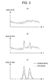
- Figs. 3(A) to 3(C) are graphs respectively showing examples of the stationary noise, the audio signal and the audio signal after removing the stationary noise.
- Fig. 3(A) indicates a signal level of the stationary noise
- Fig. 3(B) indicates a signal level of the audio signal including the stationary noise
- Fig. 3(C) indicates a signal level of the audio signal after removing the stationary noise.
- the sound collection device 1 estimates the stationary noise N'N as shown in Fig. 3(A) and generates the audio signal NE'N as shown in Fig. 3(B) .
- the sound collection device 1 simply subtracts the noise N'N from the audio signal NE'N in order to remove the stationary noise N'N from the audio signal NE'N
- the signal level of the audio signal NE'N is attenuated even in a frequency band having an utterance voice of a speaking person as shown by a dotted line in Fig. 3(C) so that the sound collection device 1 may output a sound having degraded quality.
- the sound collection device 1 may have a case where the stationary noise N'N remains in the audio signal NE'N because of the estimation error of the stationary noise N'N. In this case, the sound collection device 1 may generate a musical noise because the signal level is remarkably varied in a frequency band not having an utterance voice of a speaking person.
- the sound collection device 1 since the sound collection device 1 leaves a frequency band having an utterance voice of a speaking person as shown by a solid line in Fig. 3(C) and decreases the signal level (the gain) of the audio signal in a frequency band not having an utterance voice of a speaking person (a frequency band only having a noise), the sound collection device 1 can output a sound without degrading the quality of the utterance voice of the speaking person.
- the sound collection device 1 determines the output value CO'N in accordance with the signal level ratio of the audio signal NE'N to the stationary noise N'N, variation in the signal level is not liable to occur in the frequency band not having an utterance voice of a speaking person and occurrence of the musical noise can be prevented.
- the sound collection device 1 computes the signal level ratio of the audio signal NE'N to the stationary noise N'N, a frequency band only having a noise can be detected even when a level of an utterance voice of a speaking person is low.
- the sound collection device 1 maintains the signal level of the audio signal in the frequency band having an utterance voice of a speaking person and makes the signal level (the gain) of the audio signal in the frequency band not having an utterance voice of a speaking person to be 0, and then outputs the audio signal.
- the sound collection device 1 can maintain the signal level of the audio signal in the frequency band having an utterance voice of a speaking person and can decrease the signal level (the gain) of the audio signal in the frequency band not having an utterance voice of a speaking person to be a value greater than 0.
- Fig. 4 is a graph showing another example of a gain table. In this case, for example, as shown in Fig.
- the sound collection device 1 determines the gain of the audio signal in the frequency band not having an utterance voice of a speaking person to be 0.5 and outputs the audio signal in the frequency band not having an utterance voice of a speaking person by multiplying 0.5 to the signal level of the audio signal. With this, since the stationary noise in the frequency band having an utterance voice of a speaking person is not remarkable, the sound collection device 1 can naturally output the voice of the speaking person.
- noise gate that outputs an audio signal in which only a stationary noise is removed without degrading an utterance voice of a speaking person.
Landscapes
- Engineering & Computer Science (AREA)
- Computational Linguistics (AREA)
- Health & Medical Sciences (AREA)
- Audiology, Speech & Language Pathology (AREA)
- Human Computer Interaction (AREA)
- Physics & Mathematics (AREA)
- Acoustics & Sound (AREA)
- Multimedia (AREA)
- Quality & Reliability (AREA)
- Signal Processing (AREA)
- Circuit For Audible Band Transducer (AREA)
- Noise Elimination (AREA)
Abstract
Description
- The present invention relates to a noise gate for removing a noise included in an audio signal, a sound collection device and a noise removing method.
- A sound collection device of the related art is provided with a noise gate as a unit for removing a noise (e.g., patent document 1).
- For example, the patent document 1 discloses a noise gate device that changes a threshold value of a noise gate in accordance with an amplification degree of a head amplifier for amplifying an audio signal and removes an audio signal less than the threshold value.
- Patent Document 1:
JP-A-2006-50067 - However, the noise gate device described in the patent document 1, removes an audio signal less than a threshold value. Therefore, the problem arises that in a case where an utterance voice of a speaking person is included in the audio signal less than the threshold value, the noise gate device removes the utterance voice having a signal level less than the threshold value.
- In view of the above problem, a purpose of the invention is to provide a noise gate, a sound collection device and a noise removing method each capable of readily removing a stationary noise without degrading an audio signal.
- A noise gate according to the invention estimates a noise spectrum of a stationary noise included in an input audio signal (hereinafter, referred to as the stationary noise) based on a frequency spectrum of the input audio signal. The noise gate computes a signal level ratio of the frequency spectrum of the input audio signal to the estimated noise spectrum. The noise gate outputs the frequency spectrum of the audio signal in which the signal level in a frequency band is decreased, the frequency band having the computed signal level ratio which is less than a predetermined threshold value.
- With this configuration, the noise gate outputs a frequency spectrum of an audio signal including an utterance voice of a speaking person and suppresses a signal level in a frequency spectrum of an audio signal formed of a stationary noise so that the audio signal in which only the stationary noise is removed can be output without degrading the utterance voice of the speaking person.
- Further, the threshold value can be set to a value greater than 1 which is a value compared to the signal level ratio by a value corresponding to an estimation error of an estimation unit. Since the noise gate computes the signal level ratio to be compared to the threshold value by using the estimated stationary noise, the estimation error of the stationary noise is considered.
- With the above configuration, the noise gate can remove the stationary noise even in a case where the signal level of the stationary noise is estimated to be a value less than an actual value.
- Moreover, a sound collection device according to the invention has the above described noise gate. The sound collection device transforms an audio signal generated by collecting a sound into a frequency spectrum as a signal of a frequency domain and outputs it to the noise gate. In addition, the sound collection device inversely transforms a frequency spectrum of an audio signal output from the noise gate into an audio signal as a signal of a time domain.
- With the above configuration, the sound collection device can remove a stationary noise from the collected audio signal by using the above described noise gate. Therefore, the sound collection device can output a sound without degrading a collected utterance voice of a speaking person.
- A noise removing method according to the invention includes a process of inputting a frequency spectrum of an audio signal, a process of estimating a noise spectrum based on the frequency spectrum of the audio signal input in the inputting process, a process of computing a signal level ratio of the frequency spectrum of the audio signal to the noise spectrum estimated in the estimating process, and a process of outputting the frequency spectrum of the audio signal in which the gain in a frequency band having the signal level ratio less than a predetermined threshold value is decreased, the signal level ratio being computed in the computing process.
- In addition, the threshold value can be set to a value greater than 1 which is a value compared to the signal level ratio by a value corresponding to an estimation error of an estimation unit used in the estimating process.
- The noise gate according to the invention can output an audio signal in which only a stationary noise is removed without degrading an utterance voice of a speaking person.
-
- [
Fig. 1] Fig. 1 is a block diagram showing a function and a structure of a sound collection device. - [
Fig. 2] Fig. 2 is a graph showing an example of a gain table. - [
Fig. 3] Figs. 3(A), 3(B) and 3(C) are graphs respectively showing examples of a stationary noise, an audio signal and an audio signal after removing a noise. - [
Fig. 4] Fig. 4 is a graph showing another example of a gain table. - A sound collection device 1 according to the invention is described below with reference to
Figs. 1 and 2. Fig. 1 is a block diagram showing a function and a structure of the sound collection device 1.Fig. 2 is a graph showing an example of a gain table. The sound collection device 1 has a noise gate 12 (seeFig. 1 ). The sound collection device 1 transforms a collected audio signal NE'T into a frequency spectrum NE'N. The sound collection device 1 removes a stationary noise N'N included in the audio signal NE'N by using thenoise gate 12. At that time, the stationary noise N'N is estimated based on the frequency spectrum NE'N by thenoise gate 12. The sound collection device 1 outputs an audio signal CO'T which is generated in such a manner that a frequency spectrum CO'N after removing the stationary noise N'N is inversely transformed with respect to a time axis. Meanwhile, an end symbol of a signal in a time domain is indicated by 'T and an end symbol of a signal in a frequency domain is indicated by 'N in the descriptions below. - First, the function and the structure of the sound collection device 1 are described with reference to
Figs. 1 and 2 . As shown inFig. 1 , the sound collection device 1 includes a microphone MIC, anFFT processing unit 11, thenoise gate 12 and anIFFT processing unit 13. - The microphone MIC generates an audio signal by collecting ambient sounds. The microphone MIC outputs the generated audio signal NE'T to the
FFT processing unit 11. - The
FFT processing unit 11 is a fast Fourier transform circuit that transforms the audio signal NE'T as the signal in the time domain into the audio signal NE'N as the signal in the frequency domain and outputs the audio signal NE'N to anestimation unit 121 and anoise removal unit 122 in thenoise gate 12. - The
noise gate 12 has theestimation unit 121 and thenoise removal unit 122. - The
estimation unit 121 performs a process of estimating a stationary noise N'N included in the audio signal NE'N input from theFFT processing unit 11. Theestimation unit 121 sequentially acquires frequency spectrums (hreinafter, referred to as the audio spectrum(s)) S (NE'N) at certain sampling times of the stationary noise N'N and stores them temporarily. Theestimation unit 121 estimates frequency spectrums (hereinafter, referred to as the noise spectrum(s)) S (N'N) at certain sampling timings of the stationary noise N'N based on the plurality of times of audio spectrums S (NE'N) acquired and stored as in the above. Theestimation unit 121 outputs the estimated noise spectrums S(N'N) to thenoise removal unit 122. - For example, the noise spectrum at a certain sampling timing T is represented by S(N'N(T)), the audio spectrum at the same sampling timing T is represented by S(NE'N(T)), and the noise spectrum at the previous sampling timing T-1 is represented by S(N'N(T-1)). "α" and "β" are forgetting constants and they are, for example, set to be α=0.9 and β=0.1. The noise spectrum S(N'N(T)) is represented by the following formula 1.
-

estimation unit 121 performs an estimating process of a noise spectrum only in a case where a level of an audio signal collected by the microphone MIC is in a low state (a silent state). - The
noise removal unit 122 removes the stationary noise N'N from the audio signal NE'N input from theFFT processing unit 11 and outputs the audio signal CO'N after removing the noise to theIFFT processing unit 13. To be specific, thenoise removal unit 122 computes a signal level ratio of the audio spectrum S(NE'N) to the noise spectrum S(N'N) input from theestimation unit 121. In a case where the computed signal level ratio is less than the threshold value, thenoise removal unit 122 decreases the gain of the audio spectrum S(NE'N) in a frequency band having the signal level ratio less than the threshold value, and outputs the audio signal. - For example, the
noise removal unit 122 has a gain table TBL shown inFig. 2 . The gain table TBL determines the gain of the audio spectrum S(NE'N) in accordance with the computed signal level ratio. The gain table TBL makes the gain of the audio spectrum S(NE'N) to be 1 in a case where the signal level ratio is equal to or greater than the threshold value and makes the gain of the audio spectrum S(NE'N) to be 0 in a case where the signal level ratio is less than the threshold value. In this case, the frequency spectrum S(CO'N) at a certain sampling timing of the audio signal CO'N after removing the noise can be represented by the following formula 2. -

As a result, in a frequency band in which the signal level ratio is equal to or greater than the threshold value, thenoise removal unit 122 outputs the audio spectrum S(NE'N) as it is without changing the signal level of the audio spectrum S(NE'N). Alternatively, in a frequency band in which the signal level ratio is less than the threshold value, thenoise removal unit 122 outputs the audio spectrum S(NE'N) having a signal level which is zero since the audio spectrum S(NE'N) is assumed as the noise spectrum S(N'N). - In addition, by considering an estimation error of the stationary noise N'N, the
noise removal unit 122 may set a threshold value of the signal level ratio to a value being slightly greater than the threshold value (1.0) of the signal level ratio. With this, thenoise removal unit 122 can remove the stationary noise N'N even in a case where the signal level of the stationary noise N'N is estimated to be less than an actual level because of the estimation error of the stationary noise N'N. - The
IFFT processing unit 13 is an inverse fast Fourier transform circuit that transforms the audio signal CO'N as a signal of a frequency domain into an audio signal CO'T as a signal of a time domain. - With the above, since the sound collection device 1 can leave the audio signal as it is without attenuating the audio signal in the frequency band having an utterance voice of a speaking person, the utterance voice of the speaking person can be output without being degraded.
- The audio signal CO'N after removing the noise as the output value of the
noise gate 12 is described with reference toFigs. 3(A) to 3(C). Figs. 3(A) to 3(C) are graphs respectively showing examples of the stationary noise, the audio signal and the audio signal after removing the stationary noise.Fig. 3(A) indicates a signal level of the stationary noise,Fig. 3(B) indicates a signal level of the audio signal including the stationary noise, andFig. 3(C) indicates a signal level of the audio signal after removing the stationary noise. - The sound collection device 1 estimates the stationary noise N'N as shown in
Fig. 3(A) and generates the audio signal NE'N as shown inFig. 3(B) . When the sound collection device 1 simply subtracts the noise N'N from the audio signal NE'N in order to remove the stationary noise N'N from the audio signal NE'N, the signal level of the audio signal NE'N is attenuated even in a frequency band having an utterance voice of a speaking person as shown by a dotted line inFig. 3(C) so that the sound collection device 1 may output a sound having degraded quality. The sound collection device 1 may have a case where the stationary noise N'N remains in the audio signal NE'N because of the estimation error of the stationary noise N'N. In this case, the sound collection device 1 may generate a musical noise because the signal level is remarkably varied in a frequency band not having an utterance voice of a speaking person. - In the embodiment, since the sound collection device 1 leaves a frequency band having an utterance voice of a speaking person as shown by a solid line in
Fig. 3(C) and decreases the signal level (the gain) of the audio signal in a frequency band not having an utterance voice of a speaking person (a frequency band only having a noise), the sound collection device 1 can output a sound without degrading the quality of the utterance voice of the speaking person. In addition, since the sound collection device 1 determines the output value CO'N in accordance with the signal level ratio of the audio signal NE'N to the stationary noise N'N, variation in the signal level is not liable to occur in the frequency band not having an utterance voice of a speaking person and occurrence of the musical noise can be prevented. Further, since the sound collection device 1 computes the signal level ratio of the audio signal NE'N to the stationary noise N'N, a frequency band only having a noise can be detected even when a level of an utterance voice of a speaking person is low. - In the above embodiment, the sound collection device 1 maintains the signal level of the audio signal in the frequency band having an utterance voice of a speaking person and makes the signal level (the gain) of the audio signal in the frequency band not having an utterance voice of a speaking person to be 0, and then outputs the audio signal. However, the sound collection device 1 can maintain the signal level of the audio signal in the frequency band having an utterance voice of a speaking person and can decrease the signal level (the gain) of the audio signal in the frequency band not having an utterance voice of a speaking person to be a value greater than 0.
Fig. 4 is a graph showing another example of a gain table. In this case, for example, as shown inFig. 4 , the sound collection device 1 determines the gain of the audio signal in the frequency band not having an utterance voice of a speaking person to be 0.5 and outputs the audio signal in the frequency band not having an utterance voice of a speaking person by multiplying 0.5 to the signal level of the audio signal. With this, since the stationary noise in the frequency band having an utterance voice of a speaking person is not remarkable, the sound collection device 1 can naturally output the voice of the speaking person. - While the invention is described in detail by referring to the specific embodiment, it is understood by those of ordinary skill in the art that various modifications and changes can be made without departing from the sprit and scope of the invention. This application is based on Japanese Patent Application (
JP-2008-298332 - It is possible to provide a noise gate that outputs an audio signal in which only a stationary noise is removed without degrading an utterance voice of a speaking person.
-
- 1
- sound collection device
- 11
- FFT processing unit
- 12
- noise gate
- 121
- estimation unit
- 122
- noise removal unit
- 13
- IFFT processing unit
- MIC
- microphone
Claims (5)
- A noise gate comprising:an input unit to which a frequency spectrum of an audio signal is input;an estimation unit that estimates a noise spectrum based on the frequency spectrum of the audio signal input to the input unit; andan output unit that computes a signal level ratio of the frequency spectrum of the audio signal to the noise spectrum estimated by the estimation unit and outputs the frequency spectrum of the audio signal in which the signal level in a frequency band having the signal level ratio less than a predetermined threshold value is decreased.
- The noise gate according to claim 1, wherein the threshold value is set to a value greater than 1 which is a value compared to the signal level ratio by a value corresponding to an estimation error of the estimation unit.
- A sound collection device comprising:the noise gate according to claim 1 or 2;a sound collection unit that collects ambient sounds and generates an audio signal;a transformation unit that transforms the audio signal generated by the sound collection unit into a frequency spectrum as a signal of a frequency domain; andan inverse transformation unit that inputs the frequency spectrum transformed by the transformation unit into the input unit of the noise gate and inversely transforms the frequency spectrum of the audio signal output by the output unit of the noise gate into an audio signal as a signal in a time domain.
- A noise removing method comprising:a process of inputting a frequency spectrum of an audio signal;a process of estimating a noise spectrum based on the frequency spectrum of the audio signal input in the inputting process;a process of computing a signal level ratio of the frequency spectrum of the audio signal to the noise spectrum estimated in the estimating process; anda process of outputting the frequency spectrum of the audio signal in which the signal level in a frequency band having the signal level ratio less than a predetermined threshold value is decreased, the signal level ratio being computed in the computing process.
- The noise removing method according to claim 4, wherein the threshold value is set to a value greater than 1 which is a value compared to the signal level ratio by a value corresponding to an estimation error of an estimation unit used in the estimating process.
Applications Claiming Priority (2)
| Application Number | Priority Date | Filing Date | Title |
|---|---|---|---|
| JP2008298332A JP2010122617A (en) | 2008-11-21 | 2008-11-21 | Noise gate and sound collecting device |
| PCT/JP2009/069588 WO2010058804A1 (en) | 2008-11-21 | 2009-11-18 | Noise gate, sound collection device, and noise removal method |
Publications (3)
| Publication Number | Publication Date |
|---|---|
| EP2352148A1 true EP2352148A1 (en) | 2011-08-03 |
| EP2352148A4 EP2352148A4 (en) | 2012-08-22 |
| EP2352148B1 EP2352148B1 (en) | 2013-10-16 |
Family
ID=42198243
Family Applications (1)
| Application Number | Title | Priority Date | Filing Date |
|---|---|---|---|
| EP09827585.2A Active EP2352148B1 (en) | 2008-11-21 | 2009-11-18 | Noise gate, sound collection device, and noise removal method |
Country Status (6)
| Country | Link |
|---|---|
| US (1) | US9036830B2 (en) |
| EP (1) | EP2352148B1 (en) |
| JP (1) | JP2010122617A (en) |
| KR (1) | KR101254876B1 (en) |
| CN (1) | CN102216984B (en) |
| WO (1) | WO2010058804A1 (en) |
Cited By (2)
| Publication number | Priority date | Publication date | Assignee | Title |
|---|---|---|---|---|
| US10368173B1 (en) | 2017-03-24 | 2019-07-30 | Advanced Bionics Ag | Systems and methods for minimizing an effect of system noise generated by a cochlear implant system |
| US10595134B1 (en) | 2017-03-24 | 2020-03-17 | Advanced Bionics Ag | Systems and methods for detecting and reacting to system noise generated by a cochlear implant system |
Families Citing this family (12)
| Publication number | Priority date | Publication date | Assignee | Title |
|---|---|---|---|---|
| JP5614261B2 (en) * | 2010-11-25 | 2014-10-29 | 富士通株式会社 | Noise suppression device, noise suppression method, and program |
| FR2969435A1 (en) * | 2010-12-20 | 2012-06-22 | France Telecom | IMPULSIVE NOISE MEASUREMENT BY SPECTRAL DETECTION |
| CN102393986B (en) * | 2011-08-11 | 2013-05-08 | 重庆市科学技术研究院 | Illegal lumbering detection method, device and system based on audio frequency distinguishing |
| CN102868956B (en) * | 2012-09-24 | 2015-02-11 | 深圳市纳芯威科技有限公司 | Noise gate circuit and voice frequency power amplification equipment |
| EP3108669B1 (en) * | 2014-02-18 | 2020-04-08 | Dolby International AB | Device and method for tuning a frequency-dependent attenuation stage |
| WO2018148095A1 (en) * | 2017-02-13 | 2018-08-16 | Knowles Electronics, Llc | Soft-talk audio capture for mobile devices |
| KR102466134B1 (en) * | 2018-06-26 | 2022-11-10 | 엘지디스플레이 주식회사 | Display apparatus |
| CN112447166B (en) * | 2019-08-16 | 2024-09-10 | 阿里巴巴集团控股有限公司 | A processing method and device for target spectrum matrix |
| US11557307B2 (en) * | 2019-10-20 | 2023-01-17 | Listen AS | User voice control system |
| CN113938805B (en) * | 2020-07-14 | 2024-04-23 | 广州汽车集团股份有限公司 | Method and device for quantizing bass tone quality |
| JP7815786B2 (en) * | 2022-01-21 | 2026-02-18 | ヤマハ株式会社 | Audio processing device and audio processing method |
| JP7844965B2 (en) | 2022-03-18 | 2026-04-14 | ヤマハ株式会社 | Sound signal processing method and sound signal processing device |
Family Cites Families (17)
| Publication number | Priority date | Publication date | Assignee | Title |
|---|---|---|---|---|
| EP0226613B1 (en) | 1985-07-01 | 1993-09-15 | Motorola, Inc. | Noise supression system |
| US4811404A (en) | 1987-10-01 | 1989-03-07 | Motorola, Inc. | Noise suppression system |
| FI100840B (en) * | 1995-12-12 | 1998-02-27 | Nokia Mobile Phones Ltd | Noise cancellation and background noise canceling method in a noise and a mobile telephone |
| US6717991B1 (en) | 1998-05-27 | 2004-04-06 | Telefonaktiebolaget Lm Ericsson (Publ) | System and method for dual microphone signal noise reduction using spectral subtraction |
| US6175602B1 (en) * | 1998-05-27 | 2001-01-16 | Telefonaktiebolaget Lm Ericsson (Publ) | Signal noise reduction by spectral subtraction using linear convolution and casual filtering |
| US6459914B1 (en) | 1998-05-27 | 2002-10-01 | Telefonaktiebolaget Lm Ericsson (Publ) | Signal noise reduction by spectral subtraction using spectrum dependent exponential gain function averaging |
| US6549586B2 (en) * | 1999-04-12 | 2003-04-15 | Telefonaktiebolaget L M Ericsson | System and method for dual microphone signal noise reduction using spectral subtraction |
| US6782360B1 (en) | 1999-09-22 | 2004-08-24 | Mindspeed Technologies, Inc. | Gain quantization for a CELP speech coder |
| AU7486200A (en) * | 1999-09-22 | 2001-04-24 | Conexant Systems, Inc. | Multimode speech encoder |
| US6574593B1 (en) | 1999-09-22 | 2003-06-03 | Conexant Systems, Inc. | Codebook tables for encoding and decoding |
| US6959274B1 (en) | 1999-09-22 | 2005-10-25 | Mindspeed Technologies, Inc. | Fixed rate speech compression system and method |
| US6604070B1 (en) | 1999-09-22 | 2003-08-05 | Conexant Systems, Inc. | System of encoding and decoding speech signals |
| US6581032B1 (en) | 1999-09-22 | 2003-06-17 | Conexant Systems, Inc. | Bitstream protocol for transmission of encoded voice signals |
| CA2408496A1 (en) * | 2000-05-10 | 2001-11-15 | Adc Broadband Access Systems, Inc. | System and process for return channel spectrum manager |
| JP4483468B2 (en) | 2004-08-02 | 2010-06-16 | ソニー株式会社 | Noise reduction circuit, electronic device, noise reduction method |
| US7742746B2 (en) * | 2007-04-30 | 2010-06-22 | Qualcomm Incorporated | Automatic volume and dynamic range adjustment for mobile audio devices |
| JP2008298332A (en) | 2007-05-30 | 2008-12-11 | Aisin Seiki Co Ltd | refrigerator |
-
2008
- 2008-11-21 JP JP2008298332A patent/JP2010122617A/en active Pending
-
2009
- 2009-11-18 KR KR1020117011535A patent/KR101254876B1/en not_active Expired - Fee Related
- 2009-11-18 US US13/130,532 patent/US9036830B2/en active Active
- 2009-11-18 EP EP09827585.2A patent/EP2352148B1/en active Active
- 2009-11-18 CN CN2009801462950A patent/CN102216984B/en active Active
- 2009-11-18 WO PCT/JP2009/069588 patent/WO2010058804A1/en not_active Ceased
Cited By (2)
| Publication number | Priority date | Publication date | Assignee | Title |
|---|---|---|---|---|
| US10368173B1 (en) | 2017-03-24 | 2019-07-30 | Advanced Bionics Ag | Systems and methods for minimizing an effect of system noise generated by a cochlear implant system |
| US10595134B1 (en) | 2017-03-24 | 2020-03-17 | Advanced Bionics Ag | Systems and methods for detecting and reacting to system noise generated by a cochlear implant system |
Also Published As
| Publication number | Publication date |
|---|---|
| KR101254876B1 (en) | 2013-04-15 |
| WO2010058804A1 (en) | 2010-05-27 |
| JP2010122617A (en) | 2010-06-03 |
| EP2352148B1 (en) | 2013-10-16 |
| EP2352148A4 (en) | 2012-08-22 |
| CN102216984B (en) | 2013-03-27 |
| US20110268288A1 (en) | 2011-11-03 |
| CN102216984A (en) | 2011-10-12 |
| KR20110082176A (en) | 2011-07-18 |
| US9036830B2 (en) | 2015-05-19 |
Similar Documents
| Publication | Publication Date | Title |
|---|---|---|
| US9036830B2 (en) | Noise gate, sound collection device, and noise removing method | |
| US8560308B2 (en) | Speech sound enhancement device utilizing ratio of the ambient to background noise | |
| EP2031583B1 (en) | Fast estimation of spectral noise power density for speech signal enhancement | |
| KR101475864B1 (en) | Noise canceling device and noise canceling method | |
| EP2629294A2 (en) | System and method for dynamic residual noise shaping | |
| EP2851898B1 (en) | Voice processing apparatus, voice processing method and corresponding computer program | |
| EP2755204A1 (en) | Noise suppression device and method | |
| US8073148B2 (en) | Sound processing apparatus and method | |
| EP3276621B1 (en) | Noise suppression device and noise suppressing method | |
| US8885839B2 (en) | Signal processing method and apparatus | |
| US20080052067A1 (en) | Noise suppressor for removing irregular noise | |
| KR100778565B1 (en) | Noise removing method and device | |
| US20120197636A1 (en) | System and method for single-channel speech noise reduction | |
| EP1914727B1 (en) | Noise suppression methods and apparatuses | |
| CN103886865A (en) | Sound Processing Device, Sound Processing Method, And Program | |
| US20130322649A1 (en) | Audio processing apparatus, audio processing method, and program | |
| CN105144290A (en) | Signal processing device, signal processing method, and signal processing program | |
| US20120243702A1 (en) | Method and arrangement for processing of audio signals | |
| JP5982900B2 (en) | Noise suppression device, microphone array device, noise suppression method, and program | |
| US9697848B2 (en) | Noise suppression device and method of noise suppression | |
| CN117280414A (en) | Noise reduction based on dynamic neural network | |
| JP3171756B2 (en) | Noise removal device | |
| KR100744375B1 (en) | Apparatus and method for processing sound signal | |
| WO2024202349A1 (en) | Automatic gain control device, echo removal device, automatic gain control method, and automatic gain control program | |
| JP2001216000A (en) | Noise suppression method, audio signal processing method, and signal processing circuit |
Legal Events
| Date | Code | Title | Description |
|---|---|---|---|
| PUAI | Public reference made under article 153(3) epc to a published international application that has entered the european phase |
Free format text: ORIGINAL CODE: 0009012 |
|
| 17P | Request for examination filed |
Effective date: 20110520 |
|
| AK | Designated contracting states |
Kind code of ref document: A1 Designated state(s): AT BE BG CH CY CZ DE DK EE ES FI FR GB GR HR HU IE IS IT LI LT LU LV MC MK MT NL NO PL PT RO SE SI SK SM TR |
|
| DAX | Request for extension of the european patent (deleted) | ||
| A4 | Supplementary search report drawn up and despatched |
Effective date: 20120720 |
|
| RIC1 | Information provided on ipc code assigned before grant |
Ipc: H03G 3/34 20060101ALN20120716BHEP Ipc: G10L 21/02 20060101AFI20120716BHEP |
|
| REG | Reference to a national code |
Ref country code: DE Ref legal event code: R079 Ref document number: 602009019540 Country of ref document: DE Free format text: PREVIOUS MAIN CLASS: G10L0021020000 Ipc: G10L0021020800 |
|
| GRAP | Despatch of communication of intention to grant a patent |
Free format text: ORIGINAL CODE: EPIDOSNIGR1 |
|
| RIC1 | Information provided on ipc code assigned before grant |
Ipc: G10L 21/0232 20130101ALN20130404BHEP Ipc: H03G 3/34 20060101ALN20130404BHEP Ipc: G10L 21/0208 20130101AFI20130404BHEP |
|
| RIC1 | Information provided on ipc code assigned before grant |
Ipc: H03G 3/34 20060101ALN20130410BHEP Ipc: G10L 21/0208 20130101AFI20130410BHEP Ipc: G10L 21/0232 20130101ALN20130410BHEP |
|
| INTG | Intention to grant announced |
Effective date: 20130423 |
|
| GRAS | Grant fee paid |
Free format text: ORIGINAL CODE: EPIDOSNIGR3 |
|
| GRAA | (expected) grant |
Free format text: ORIGINAL CODE: 0009210 |
|
| AK | Designated contracting states |
Kind code of ref document: B1 Designated state(s): AT BE BG CH CY CZ DE DK EE ES FI FR GB GR HR HU IE IS IT LI LT LU LV MC MK MT NL NO PL PT RO SE SI SK SM TR |
|
| REG | Reference to a national code |
Ref country code: GB Ref legal event code: FG4D |
|
| REG | Reference to a national code |
Ref country code: CH Ref legal event code: EP |
|
| REG | Reference to a national code |
Ref country code: IE Ref legal event code: FG4D |
|
| REG | Reference to a national code |
Ref country code: AT Ref legal event code: REF Ref document number: 636834 Country of ref document: AT Kind code of ref document: T Effective date: 20131115 |
|
| REG | Reference to a national code |
Ref country code: DE Ref legal event code: R096 Ref document number: 602009019540 Country of ref document: DE Effective date: 20131212 |
|
| REG | Reference to a national code |
Ref country code: NL Ref legal event code: VDEP Effective date: 20131016 |
|
| REG | Reference to a national code |
Ref country code: AT Ref legal event code: MK05 Ref document number: 636834 Country of ref document: AT Kind code of ref document: T Effective date: 20131016 |
|
| REG | Reference to a national code |
Ref country code: LT Ref legal event code: MG4D |
|
| PG25 | Lapsed in a contracting state [announced via postgrant information from national office to epo] |
Ref country code: LT Free format text: LAPSE BECAUSE OF FAILURE TO SUBMIT A TRANSLATION OF THE DESCRIPTION OR TO PAY THE FEE WITHIN THE PRESCRIBED TIME-LIMIT Effective date: 20131016 Ref country code: FI Free format text: LAPSE BECAUSE OF FAILURE TO SUBMIT A TRANSLATION OF THE DESCRIPTION OR TO PAY THE FEE WITHIN THE PRESCRIBED TIME-LIMIT Effective date: 20131016 Ref country code: NL Free format text: LAPSE BECAUSE OF FAILURE TO SUBMIT A TRANSLATION OF THE DESCRIPTION OR TO PAY THE FEE WITHIN THE PRESCRIBED TIME-LIMIT Effective date: 20131016 Ref country code: IS Free format text: LAPSE BECAUSE OF FAILURE TO SUBMIT A TRANSLATION OF THE DESCRIPTION OR TO PAY THE FEE WITHIN THE PRESCRIBED TIME-LIMIT Effective date: 20140216 Ref country code: BE Free format text: LAPSE BECAUSE OF FAILURE TO SUBMIT A TRANSLATION OF THE DESCRIPTION OR TO PAY THE FEE WITHIN THE PRESCRIBED TIME-LIMIT Effective date: 20131016 Ref country code: SE Free format text: LAPSE BECAUSE OF FAILURE TO SUBMIT A TRANSLATION OF THE DESCRIPTION OR TO PAY THE FEE WITHIN THE PRESCRIBED TIME-LIMIT Effective date: 20131016 Ref country code: NO Free format text: LAPSE BECAUSE OF FAILURE TO SUBMIT A TRANSLATION OF THE DESCRIPTION OR TO PAY THE FEE WITHIN THE PRESCRIBED TIME-LIMIT Effective date: 20140116 Ref country code: HR Free format text: LAPSE BECAUSE OF FAILURE TO SUBMIT A TRANSLATION OF THE DESCRIPTION OR TO PAY THE FEE WITHIN THE PRESCRIBED TIME-LIMIT Effective date: 20131016 |
|
| PG25 | Lapsed in a contracting state [announced via postgrant information from national office to epo] |
Ref country code: AT Free format text: LAPSE BECAUSE OF FAILURE TO SUBMIT A TRANSLATION OF THE DESCRIPTION OR TO PAY THE FEE WITHIN THE PRESCRIBED TIME-LIMIT Effective date: 20131016 Ref country code: LV Free format text: LAPSE BECAUSE OF FAILURE TO SUBMIT A TRANSLATION OF THE DESCRIPTION OR TO PAY THE FEE WITHIN THE PRESCRIBED TIME-LIMIT Effective date: 20131016 Ref country code: ES Free format text: LAPSE BECAUSE OF FAILURE TO SUBMIT A TRANSLATION OF THE DESCRIPTION OR TO PAY THE FEE WITHIN THE PRESCRIBED TIME-LIMIT Effective date: 20131016 Ref country code: CY Free format text: LAPSE BECAUSE OF FAILURE TO SUBMIT A TRANSLATION OF THE DESCRIPTION OR TO PAY THE FEE WITHIN THE PRESCRIBED TIME-LIMIT Effective date: 20131016 |
|
| PG25 | Lapsed in a contracting state [announced via postgrant information from national office to epo] |
Ref country code: PT Free format text: LAPSE BECAUSE OF FAILURE TO SUBMIT A TRANSLATION OF THE DESCRIPTION OR TO PAY THE FEE WITHIN THE PRESCRIBED TIME-LIMIT Effective date: 20140217 |
|
| REG | Reference to a national code |
Ref country code: CH Ref legal event code: PL |
|
| REG | Reference to a national code |
Ref country code: DE Ref legal event code: R097 Ref document number: 602009019540 Country of ref document: DE |
|
| PG25 | Lapsed in a contracting state [announced via postgrant information from national office to epo] |
Ref country code: EE Free format text: LAPSE BECAUSE OF FAILURE TO SUBMIT A TRANSLATION OF THE DESCRIPTION OR TO PAY THE FEE WITHIN THE PRESCRIBED TIME-LIMIT Effective date: 20131016 Ref country code: CH Free format text: LAPSE BECAUSE OF NON-PAYMENT OF DUE FEES Effective date: 20131130 Ref country code: LI Free format text: LAPSE BECAUSE OF NON-PAYMENT OF DUE FEES Effective date: 20131130 Ref country code: MC Free format text: LAPSE BECAUSE OF FAILURE TO SUBMIT A TRANSLATION OF THE DESCRIPTION OR TO PAY THE FEE WITHIN THE PRESCRIBED TIME-LIMIT Effective date: 20131016 |
|
| PLBE | No opposition filed within time limit |
Free format text: ORIGINAL CODE: 0009261 |
|
| STAA | Information on the status of an ep patent application or granted ep patent |
Free format text: STATUS: NO OPPOSITION FILED WITHIN TIME LIMIT |
|
| REG | Reference to a national code |
Ref country code: IE Ref legal event code: MM4A |
|
| PG25 | Lapsed in a contracting state [announced via postgrant information from national office to epo] |
Ref country code: IT Free format text: LAPSE BECAUSE OF FAILURE TO SUBMIT A TRANSLATION OF THE DESCRIPTION OR TO PAY THE FEE WITHIN THE PRESCRIBED TIME-LIMIT Effective date: 20131016 Ref country code: CZ Free format text: LAPSE BECAUSE OF FAILURE TO SUBMIT A TRANSLATION OF THE DESCRIPTION OR TO PAY THE FEE WITHIN THE PRESCRIBED TIME-LIMIT Effective date: 20131016 Ref country code: RO Free format text: LAPSE BECAUSE OF FAILURE TO SUBMIT A TRANSLATION OF THE DESCRIPTION OR TO PAY THE FEE WITHIN THE PRESCRIBED TIME-LIMIT Effective date: 20131016 Ref country code: SK Free format text: LAPSE BECAUSE OF FAILURE TO SUBMIT A TRANSLATION OF THE DESCRIPTION OR TO PAY THE FEE WITHIN THE PRESCRIBED TIME-LIMIT Effective date: 20131016 Ref country code: PL Free format text: LAPSE BECAUSE OF FAILURE TO SUBMIT A TRANSLATION OF THE DESCRIPTION OR TO PAY THE FEE WITHIN THE PRESCRIBED TIME-LIMIT Effective date: 20131016 |
|
| 26N | No opposition filed |
Effective date: 20140717 |
|
| GBPC | Gb: european patent ceased through non-payment of renewal fee |
Effective date: 20140116 |
|
| PG25 | Lapsed in a contracting state [announced via postgrant information from national office to epo] |
Ref country code: DK Free format text: LAPSE BECAUSE OF FAILURE TO SUBMIT A TRANSLATION OF THE DESCRIPTION OR TO PAY THE FEE WITHIN THE PRESCRIBED TIME-LIMIT Effective date: 20131016 |
|
| REG | Reference to a national code |
Ref country code: DE Ref legal event code: R097 Ref document number: 602009019540 Country of ref document: DE Effective date: 20140717 |
|
| PG25 | Lapsed in a contracting state [announced via postgrant information from national office to epo] |
Ref country code: IE Free format text: LAPSE BECAUSE OF NON-PAYMENT OF DUE FEES Effective date: 20131118 |
|
| PG25 | Lapsed in a contracting state [announced via postgrant information from national office to epo] |
Ref country code: GB Free format text: LAPSE BECAUSE OF NON-PAYMENT OF DUE FEES Effective date: 20140116 |
|
| PG25 | Lapsed in a contracting state [announced via postgrant information from national office to epo] |
Ref country code: SI Free format text: LAPSE BECAUSE OF FAILURE TO SUBMIT A TRANSLATION OF THE DESCRIPTION OR TO PAY THE FEE WITHIN THE PRESCRIBED TIME-LIMIT Effective date: 20131016 |
|
| PG25 | Lapsed in a contracting state [announced via postgrant information from national office to epo] |
Ref country code: SM Free format text: LAPSE BECAUSE OF FAILURE TO SUBMIT A TRANSLATION OF THE DESCRIPTION OR TO PAY THE FEE WITHIN THE PRESCRIBED TIME-LIMIT Effective date: 20131016 |
|
| PG25 | Lapsed in a contracting state [announced via postgrant information from national office to epo] |
Ref country code: TR Free format text: LAPSE BECAUSE OF FAILURE TO SUBMIT A TRANSLATION OF THE DESCRIPTION OR TO PAY THE FEE WITHIN THE PRESCRIBED TIME-LIMIT Effective date: 20131016 |
|
| PG25 | Lapsed in a contracting state [announced via postgrant information from national office to epo] |
Ref country code: HU Free format text: LAPSE BECAUSE OF FAILURE TO SUBMIT A TRANSLATION OF THE DESCRIPTION OR TO PAY THE FEE WITHIN THE PRESCRIBED TIME-LIMIT; INVALID AB INITIO Effective date: 20091118 Ref country code: LU Free format text: LAPSE BECAUSE OF NON-PAYMENT OF DUE FEES Effective date: 20131118 Ref country code: MK Free format text: LAPSE BECAUSE OF FAILURE TO SUBMIT A TRANSLATION OF THE DESCRIPTION OR TO PAY THE FEE WITHIN THE PRESCRIBED TIME-LIMIT Effective date: 20131016 Ref country code: BG Free format text: LAPSE BECAUSE OF FAILURE TO SUBMIT A TRANSLATION OF THE DESCRIPTION OR TO PAY THE FEE WITHIN THE PRESCRIBED TIME-LIMIT Effective date: 20131016 |
|
| PG25 | Lapsed in a contracting state [announced via postgrant information from national office to epo] |
Ref country code: GR Free format text: LAPSE BECAUSE OF NON-PAYMENT OF DUE FEES Effective date: 20131016 Ref country code: MT Free format text: LAPSE BECAUSE OF FAILURE TO SUBMIT A TRANSLATION OF THE DESCRIPTION OR TO PAY THE FEE WITHIN THE PRESCRIBED TIME-LIMIT Effective date: 20131016 |
|
| REG | Reference to a national code |
Ref country code: FR Ref legal event code: PLFP Year of fee payment: 7 |
|
| PG25 | Lapsed in a contracting state [announced via postgrant information from national office to epo] |
Ref country code: GR Free format text: LAPSE BECAUSE OF FAILURE TO SUBMIT A TRANSLATION OF THE DESCRIPTION OR TO PAY THE FEE WITHIN THE PRESCRIBED TIME-LIMIT Effective date: 20140117 |
|
| REG | Reference to a national code |
Ref country code: FR Ref legal event code: PLFP Year of fee payment: 8 |
|
| REG | Reference to a national code |
Ref country code: FR Ref legal event code: PLFP Year of fee payment: 9 |
|
| PGFP | Annual fee paid to national office [announced via postgrant information from national office to epo] |
Ref country code: FR Payment date: 20191120 Year of fee payment: 11 |
|
| PG25 | Lapsed in a contracting state [announced via postgrant information from national office to epo] |
Ref country code: FR Free format text: LAPSE BECAUSE OF NON-PAYMENT OF DUE FEES Effective date: 20201130 |
|
| PGFP | Annual fee paid to national office [announced via postgrant information from national office to epo] |
Ref country code: DE Payment date: 20251119 Year of fee payment: 17 |