EP2351953A1 - Contaminant sealing device - Google Patents
Contaminant sealing device Download PDFInfo
- Publication number
- EP2351953A1 EP2351953A1 EP10811575A EP10811575A EP2351953A1 EP 2351953 A1 EP2351953 A1 EP 2351953A1 EP 10811575 A EP10811575 A EP 10811575A EP 10811575 A EP10811575 A EP 10811575A EP 2351953 A1 EP2351953 A1 EP 2351953A1
- Authority
- EP
- European Patent Office
- Prior art keywords
- shape
- sealing device
- substantial
- annular packing
- annular
- Prior art date
- Legal status (The legal status is an assumption and is not a legal conclusion. Google has not performed a legal analysis and makes no representation as to the accuracy of the status listed.)
- Withdrawn
Links
- 238000007789 sealing Methods 0.000 title claims abstract description 40
- 239000000356 contaminant Substances 0.000 title claims abstract description 30
- 238000012856 packing Methods 0.000 claims abstract description 73
- 239000012530 fluid Substances 0.000 claims abstract description 25
- 125000006850 spacer group Chemical group 0.000 claims description 16
- 230000000694 effects Effects 0.000 description 4
- 239000012535 impurity Substances 0.000 description 3
- 229920002943 EPDM rubber Polymers 0.000 description 1
- 229920000181 Ethylene propylene rubber Polymers 0.000 description 1
- 229920000459 Nitrile rubber Polymers 0.000 description 1
- 239000000463 material Substances 0.000 description 1
- 238000012986 modification Methods 0.000 description 1
- 230000004048 modification Effects 0.000 description 1
- 230000002093 peripheral effect Effects 0.000 description 1
Images



Classifications
-
- F—MECHANICAL ENGINEERING; LIGHTING; HEATING; WEAPONS; BLASTING
- F16—ENGINEERING ELEMENTS AND UNITS; GENERAL MEASURES FOR PRODUCING AND MAINTAINING EFFECTIVE FUNCTIONING OF MACHINES OR INSTALLATIONS; THERMAL INSULATION IN GENERAL
- F16J—PISTONS; CYLINDERS; SEALINGS
- F16J15/00—Sealings
- F16J15/16—Sealings between relatively-moving surfaces
- F16J15/32—Sealings between relatively-moving surfaces with elastic sealings, e.g. O-rings
- F16J15/3204—Sealings between relatively-moving surfaces with elastic sealings, e.g. O-rings with at least one lip
-
- F—MECHANICAL ENGINEERING; LIGHTING; HEATING; WEAPONS; BLASTING
- F16—ENGINEERING ELEMENTS AND UNITS; GENERAL MEASURES FOR PRODUCING AND MAINTAINING EFFECTIVE FUNCTIONING OF MACHINES OR INSTALLATIONS; THERMAL INSULATION IN GENERAL
- F16K—VALVES; TAPS; COCKS; ACTUATING-FLOATS; DEVICES FOR VENTING OR AERATING
- F16K31/00—Actuating devices; Operating means; Releasing devices
- F16K31/02—Actuating devices; Operating means; Releasing devices electric; magnetic
- F16K31/06—Actuating devices; Operating means; Releasing devices electric; magnetic using a magnet, e.g. diaphragm valves, cutting off by means of a liquid
- F16K31/0603—Multiple-way valves
- F16K31/0624—Lift valves
- F16K31/0627—Lift valves with movable valve member positioned between seats
-
- F—MECHANICAL ENGINEERING; LIGHTING; HEATING; WEAPONS; BLASTING
- F16—ENGINEERING ELEMENTS AND UNITS; GENERAL MEASURES FOR PRODUCING AND MAINTAINING EFFECTIVE FUNCTIONING OF MACHINES OR INSTALLATIONS; THERMAL INSULATION IN GENERAL
- F16K—VALVES; TAPS; COCKS; ACTUATING-FLOATS; DEVICES FOR VENTING OR AERATING
- F16K41/00—Spindle sealings
- F16K41/02—Spindle sealings with stuffing-box ; Sealing rings
- F16K41/08—Spindle sealings with stuffing-box ; Sealing rings with at least one ring provided with axially-protruding peripheral closing-lip
Definitions
- the term "contaminant sealing” means sealing contaminants included in the sealed fluid, and the sealed fluid is not completely sealed.
- the contaminant sealing device is the contaminant sealing device according to the first aspect characterized in that the annular packing is mounted in an annular groove of the outer member and is disposed so that an upper portion of the cross-sectional substantial Y shape makes intimate contact with the outer member, and a lower portion slides along the inner member.
- the second characteristic in addition to the effects of the first characteristic, ensuring the space for mounting the annular packing and mounting the annular packing can be made easier.
- the contaminant sealing device is the contaminant sealing device according to the first or second aspects characterized in that an annular spacer is arranged on one side surface of the cross-sectional substantial Y shape of the annular packing, the annular packing is configured to be capable of being mounted using a pressing jig with the annular spacer interposed therebetween, and interference of the annular packing can be managed by adjusting the position in which the annular spacer is incorporated. According to the third characteristic, the interference of the annular packing can be properly managed, and the amount of change in the friction of the sliding part can be minimized.
- the contaminant sealing device is characterized in that the contaminant sealing device of any of the first through third aspects is incorporated into a capacity control solenoid valve. According to the fourth characteristic, impurities can be prevented from entering into the minuscule gap between the valve body and the valve housing without enlarging the capacity control solenoid valve, and as a result, there is no need to increase the thrust of the solenoid.
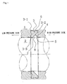
- a high-pressure fluid acts on a space 8 having a substantially triangular shape in cross section, which is formed by the back portion 4 of the substantial Y shape, one side surface of the annular groove 5 of the outer member 1, and the sliding surface of the inner member 2.
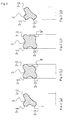
- FIG. 2 is a front cross-sectional view showing another example of the annular packing 3.
- the annular packing 3 is molded into a ring shape from hydrogenated nitrile rubber (HNBR), ethylene propylene rubber (EPDM), or another material.
- the cross-sectional shape has in FIG. 2(a) a Y shape, in FIG. 2(b) a substantial Y shape in which a substantially trapezoidal protuberance 9 having flat vertex is provided in the center of the back portion 4 of the Y shape, and in FIG. 2(c) a substantial Y shape in which a substantially triangular protuberance 9' having a rounded vertex is provided in the center of the back portion 4 of the Y shape.
- HNBR hydrogenated nitrile rubber
- EPDM ethylene propylene rubber
- FIG. 3 shows the results of a friction test with the annular packing 3 having the substantially Y-shaped cross section of the present invention.
- the test conditions were the same as those used with the X ring of Prior Art 1, the seal diameter 0 being 4.8 mm and the interference being 0.1 mm.
- This graph shows that when the annular packing 3 having the substantially Y-shaped cross section of the present invention is used, the friction is reduced to 1/2 to 1/3 in comparison with using a conventional X ring. It is clear that even if the pressure of the sealed fluid increases, the friction remains substantially constant. The reason the friction is reduced is because in the annular packing 3 having the substantially Y-shaped cross section of the present invention, the high-pressure-side sliding part of the conventional X ring has been omitted.
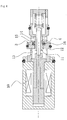
- FIG. 4 is a front cross-sectional view showing a case in which the annular packing 3 having the substantially Y-shaped cross section of the present invention has been applied to a capacity control solenoid valve.
- the annular packing 3 is mounted in a narrow area 15 between a low-pressure side 13 and a high-pressure side 14, preventing contaminants from entering into the low-pressure side 13.
- the annular packing 3 is mounted in an annular groove 16 provided to the valve housing 12, the lower side of the substantial Y shape slides along the valve body 11, the upper side is held firmly against the annular groove 16, and the back portion 4 of the substantial Y shape is disposed so as to face the high-pressure side 14.
- FIGS. 5 and 6 are front cross-sectional views for describing a case in which the annular packing 3 having the substantially Y-shaped cross section of the present invention is mounted in a capacity control solenoid valve, for example, wherein the same symbols shown in FIG. 4 indicate the same components.
- a diameter-enlarging part 17 for mounting the annular packing 3 is provided to the inside surface of the valve housing 12 in the narrow area 15 between the low-pressure side 13 and the high-pressure side 14.
- This diameter-enlarging part 17 is shaped such that its left side is connected to the narrow area 15, while is right side is open, as shown in FIG. 6 .
Landscapes
- Engineering & Computer Science (AREA)
- General Engineering & Computer Science (AREA)
- Mechanical Engineering (AREA)
- Sealing Devices (AREA)
- Magnetically Actuated Valves (AREA)
- Sealing With Elastic Sealing Lips (AREA)
Abstract
Description
- The present invention relates to a contaminant sealing device comprising an annular packing for reciprocating movement or rotation, wherein the packing is attached to one of two members that face each other and is capable of sliding firmly against the other of the two members. The contaminant sealing device of the present invention is used as a device for sealing reciprocating components in a solenoid valve, for example.
- Conventionally, in the narrow area between the valve and the body of a solenoid valve, for example, contaminants from the outside enter and cause poor performance. There are cases in which a sealing mechanism is installed in this area to prevent contaminants from entering, but when common conventionally known packing or the like is used it is packed in hermetically, therefore causing problems of high friction.
To reduce friction, an X ring (hereinbelow referred to as "Prior Art 1;" seePatent Literature 1, for example) is used, which has an X shape in cross section and which is intended to reducing the sliding of a lip sliding part as shown inFIG. 7 , and the surface area of the lip sliding part is preferably reduced, but even when the X ring ofPrior Art 1 is used, problems of fluctuating friction occur as shown inFIG. 8 when pressure changes occur in the fluid being sealed.
A friction test was performed with aseal diameter 0 of 4.8 mm and an interference of 0.1 mm. The pressure [MPa] along the horizontal axis ofFIG. 8 shows the pressure difference between the high pressure side and the low pressure side. - The invention shown in
FIG. 9 (hereinbelow referred to as "Prior Art 2;" seePatent Literature 2, for example) is known as being intended to suppress changes in friction and maintain stable sealing performance even when the pressure of the fluid being sealed has changed.
In the invention of PriorArt 2, a side ring and a back ring are attached in addition to a seal ring, and the fluid pressure acting on the back ring is blocked by the side ring even when the pressure of the fluid being sealed has changed, preventing deformation of the back ring and thereby suppressing the change in friction on the seal ring. This invention therefore has had the drawbacks of having a large number of components and requiring a large amount of space. -
- Patent Reference 1: Japanese Laid-open Patent Application No.
2006-266279 - Patent Reference 2: Japanese Laid-open Patent Application No.
2006-112486 - In view of the fact that complete sealing rather than fluid sealing is not necessary in a contaminant seal, an object of the present invention is to provide a contaminant sealing device wherein the conventional high-pressure-side sliding part of the X ring is omitted, the sliding part is provided to the low pressure side, and the arrangement structure is intended to achieve a balance between the expansion force of the sealing ring itself which occurs with the fastening of the sealing ring, and the pressure of the sealed fluid acting on the outer surface of the sealing ring; whereby the pressure force of the sliding part does not increase proportionately even if the sealed fluid pressure increases, and the amount of change in the friction of the sliding part can be reduced relative to the change in the sealed fluid pressure.
Another object of the present invention is to provide a contaminant sealing device wherein the number of components can be reduced and the required space can be reduced.
Another object of the present invention is to provide a contaminant sealing device wherein the interference of the sealing ring can be properly managed.
In the present invention, the term "contaminant sealing" means sealing contaminants included in the sealed fluid, and the sealed fluid is not completely sealed. - The contaminant sealing device according to a first aspect of the present invention for achieving the object described above is a sealing device comprising an annular packing for reciprocating movement or rotation, the packing being mounted to one of two members that face each other and being disposed in slidably intimate contact against another of the two members; the sealing device characterized in that the cross-sectional shape of the annular packing is a substantial Y shape, the back portion of the substantial Y shape is disposed so as to face a high pressure side, and a high-pressure fluid acts on a space formed by the back portion of the substantial Y shape and the two members that face each other.
- According to the first characteristic, the pressure force of the sliding part does not increase proportionately even if the sealed fluid pressure increases, and the amount of change in the friction of the sliding part can be reduced relative to the change in the sealed fluid pressure.
The number of components can also be reduced, and the required space can be reduced. - The contaminant sealing device according to a second aspect of the present invention is the contaminant sealing device according to the first aspect characterized in that the annular packing is mounted in an annular groove of the outer member and is disposed so that an upper portion of the cross-sectional substantial Y shape makes intimate contact with the outer member, and a lower portion slides along the inner member.
According to the second characteristic, in addition to the effects of the first characteristic, ensuring the space for mounting the annular packing and mounting the annular packing can be made easier. - The contaminant sealing device according to a third aspect of the present invention is the contaminant sealing device according to the first or second aspects characterized in that an annular spacer is arranged on one side surface of the cross-sectional substantial Y shape of the annular packing, the annular packing is configured to be capable of being mounted using a pressing jig with the annular spacer interposed therebetween, and interference of the annular packing can be managed by adjusting the position in which the annular spacer is incorporated.
According to the third characteristic, the interference of the annular packing can be properly managed, and the amount of change in the friction of the sliding part can be minimized.
The contaminant sealing device according to a fourth aspect of the present invention is characterized in that the contaminant sealing device of any of the first through third aspects is incorporated into a capacity control solenoid valve.
According to the fourth characteristic, impurities can be prevented from entering into the minuscule gap between the valve body and the valve housing without enlarging the capacity control solenoid valve, and as a result, there is no need to increase the thrust of the solenoid. - The present invention exhibits superior effects such as the following.
- (1) The pressure force of the sliding part does not increase proportionately even if the sealed fluid pressure increases, and the amount of change in the friction of the sliding part can be reduced relative to the change in the sealed fluid pressure by forming the cross-sectional shape of the annular packing into a substantial Y shape, disposing the annular packing so that the back portion of the substantial Y shape faces the high pressure side, and causing the high-pressure fluid to act on the space formed by the back portion of the substantial Y shape and the two members that face each other.
The number of components can also be reduced, and the required space can be reduced. - (2) It is possible to more readily ensure the space for mounting the annular packing and mounting the annular packing by mounting the annular packing in the annular groove of the outer member and disposing the annular packing so that that the upper portion of the cross-sectional substantial Y shape is held firmly against the outer member and the lower portion slides along the inner member.
- (3) The interference of the annular packing can be properly managed, and the amount of change in the friction of the sliding part can be minimized by placing the annular spacer on one side surface of the cross-sectional substantial Y shape of the annular packing, configuring the annular packing to be capable of being mounted by the pressing jig via the annular spacer, and enabling the interference of the annular packing to be managed by adjusting the incorporated position of the annular spacer.
- (4) By incorporating the contaminant sealing device of the present invention into a capacity control solenoid valve, impurities can be prevented from entering into the minuscule gap between the valve body and the valve housing without enlarging the capacity control solenoid valve; as a result, there is no need to increase the thrust of the solenoid.
-
-
FIG. 1 is a front cross-sectional view showing a contaminant sealing device according to an embodiment of the present invention; -
FIG. 2 is a front cross-sectional view showing an example of an annular packing according to an embodiment of the present invention; -
FIG. 3 shows the results of a friction test when the annular packing having the substantially Y-shaped cross section of the present invention is used; -
FIG. 4 is a front cross-sectional view showing a case in which the annular packing having the substantially Y-shaped cross section of the present invention has been applied to a capacity control solenoid valve; -
FIG. 5 is a partial front cross-sectional view for describing a case in which the annular packing having the substantially Y-shaped cross section of the present invention is mounted in a capacity control solenoid valve; -
FIG. 6 is a front cross-sectional view showing a state in which the annular packing having the substantially Y-shaped cross section of the present invention has been mounted in a capacity control solenoid valve; -
-
FIG. 7 is a front cross-sectional view showing an X ring according to PriorArt 1; -
FIG. 8 shows the result of a friction test in a case in which the X ring of PriorArt 1 is used; and -
FIG. 9 is a front cross-sectional view showingPrior Art 2. - Modes for carrying out the contaminant sealing device according to the present invention are described in detail with reference being made to the accompanying drawings, but the present invention is not to be interpreter as being limited to these modes. Any of a variety of modifications, revisions, and improvements can be added based on the knowledge of those skilled in the art as long as they do not deviate from the scope of the present invention.
-
FIG. 1 is a front cross-sectional view showing a contaminant sealing device, wherein, between amember 1 positioned on the outer side and amember 2 positioned on the inner side, anannular groove 5 for attaching anannular packing 3 is provided to theouter member 1. Theannular packing 3 is placed so that the inner peripheral surface of theannular packing 3 is capable of sliding firmly against theinner member 2. The cross-sectional shape of theannular packing 3 has a substantial Y shape, and aback portion 4 of the substantial Y shape is disposed so as to face the high pressure side. Therefore, a high-pressure fluid acts on a space 8 having a substantially triangular shape in cross section, which is formed by theback portion 4 of the substantial Y shape, one side surface of theannular groove 5 of theouter member 1, and the sliding surface of theinner member 2. - In the example shown in
FIG. 1 , theannular packing 3 is mounted in theannular groove 5 of theouter member 1, anupper portion 6 of the cross-sectional substantial Y shape is held firmly against theannular groove 5 of the outer member, and alower portion 7 is disposed so as to slide along theinner member 2. When theannular packing 3 is mounted in the annular groove of theinner member 2, theupper portion 6 of the cross-sectional substantial Y shape is held firmly in the annular groove of theinner member 2, and thelower portion 7 is disposed so as to slide along theinner member 2.
Thus, a first characteristic of theannular packing 3 having a substantially Y-shaped cross section according to the present invention is that the conventional high-pressure-side sliding part of the X ring is omitted to have fewer sliding parts, and the sliding part is provided to the low pressure side. A second characteristic is that the expansion force relative to the force of fastening theannular packing 3 is reduced by the pressure of the sealed fluid. - The term "substantial Y shape" herein means that the essential shape is preferably the shape of the letter Y, wherein three outer points 3-1, 3-2, and 3-3 of the substantial Y shape constitute seal parts. The term "back portion of the substantial Y shape" refers to the portion indicated by the
symbol 4 inFIG. 1 , which is, among the short sides and long side constituting the substantial Y shape, the surface of the long side on the side opposite the short sides. The term "upper portion of the substantial Y shape" refers to the upper side of the Y shape, i.e. the portion indicated by thesymbol 6 inFIG. 1 , and the term "lower portion of the substantial Y shape" refers to the lower side of the Y shape, i.e. the portion indicated by thesymbol 7 inFIG. 1 . -
FIG. 2 is a front cross-sectional view showing another example of theannular packing 3.
Theannular packing 3 is molded into a ring shape from hydrogenated nitrile rubber (HNBR), ethylene propylene rubber (EPDM), or another material. The cross-sectional shape has inFIG. 2(a) a Y shape, inFIG. 2(b) a substantial Y shape in which a substantiallytrapezoidal protuberance 9 having flat vertex is provided in the center of theback portion 4 of the Y shape, and inFIG. 2(c) a substantial Y shape in which a substantially triangular protuberance 9' having a rounded vertex is provided in the center of theback portion 4 of the Y shape. In FIGS. (a), (b), and (c), the distal ends of the three outer points 3-1, 3-2, and 3-3 of the substantial Y shape all have rounded shapes, but the distal ends may also be linear, being held firmly against themembers FIG. 2(d) .
A line connecting the three outer points 3-1, 3-2, and 3-3 of the substantial Y shape is a smoothly curved line recessed inward as shown in the drawings. InFIG. 1 , the line joining the two outer points 3-2 and 3-3 is a straight line, which is different fromFIG. 2(a) . -
FIG. 3 shows the results of a friction test with theannular packing 3 having the substantially Y-shaped cross section of the present invention. The test conditions were the same as those used with the X ring ofPrior Art 1, theseal diameter 0 being 4.8 mm and the interference being 0.1 mm.
This graph shows that when theannular packing 3 having the substantially Y-shaped cross section of the present invention is used, the friction is reduced to 1/2 to 1/3 in comparison with using a conventional X ring. It is clear that even if the pressure of the sealed fluid increases, the friction remains substantially constant.
The reason the friction is reduced is because in theannular packing 3 having the substantially Y-shaped cross section of the present invention, the high-pressure-side sliding part of the conventional X ring has been omitted.
The reason the friction remains substantially constant even when the pressure increases is believed to be because when the elasticannular packing 3 is appropriately fastened, a reacting expansion force occurs and has the effect of increasing friction, but a balance is achieved between this expansion force and the force acting to compress the sliding part 3-3 of theannular packing 3 caused by the pressure of the sealed fluid acting on theback portion 4 of the substantially Y-shaped annular packing 3 (the force acting in a direction away from the sliding member on the opposite side), whereby the friction remains substantially constant. -
FIG. 4 is a front cross-sectional view showing a case in which theannular packing 3 having the substantially Y-shaped cross section of the present invention has been applied to a capacity control solenoid valve.
In this example, between avalve housing 12 and avalve body 11 driven back and forth in a left-right direction by asolenoid 10, theannular packing 3 is mounted in anarrow area 15 between a low-pressure side 13 and a high-pressure side 14, preventing contaminants from entering into the low-pressure side 13.
Theannular packing 3 is mounted in anannular groove 16 provided to thevalve housing 12, the lower side of the substantial Y shape slides along thevalve body 11, the upper side is held firmly against theannular groove 16, and theback portion 4 of the substantial Y shape is disposed so as to face the high-pressure side 14.
Thus, by incorporating theannular packing 3 having the substantially Y-shaped cross section of the present invention into a capacity control solenoid valve, impurities can be prevented from entering into the minuscule gap between the valve body and the valve housing without enlarging the capacity control solenoid valve, and as a result, there is no need to increase the thrust of the solenoid. -
FIGS. 5 and6 are front cross-sectional views for describing a case in which theannular packing 3 having the substantially Y-shaped cross section of the present invention is mounted in a capacity control solenoid valve, for example, wherein the same symbols shown inFIG. 4 indicate the same components.
In this example, between thevalve body 11 and thevalve housing 12, a diameter-enlargingpart 17 for mounting theannular packing 3 is provided to the inside surface of thevalve housing 12 in thenarrow area 15 between the low-pressure side 13 and the high-pressure side 14. This diameter-enlargingpart 17 is shaped such that its left side is connected to thenarrow area 15, while is right side is open, as shown inFIG. 6 . - To mount the
annular packing 3, as shown inFIG.5 ,theannular packing 3 is disposed so that the back portion of the substantial Y shape faces the high-pressure side 14 (the left side of the drawing) and the upper side faces the diameter-enlargingpart 17 of the inside surface of thevalve housing 12, and with anannular spacer 18 having been placed on thefront side 19 of the cross-sectional substantial Y shape of theannular packing 3, theannular packing 3 is pressed from the right (the open side) by apressing jig 20. After this pressing, theannular spacer 18 is left in and thepressing jig 20 is pulled out. Theannular spacer 18 formed with dimensions so as to fit with the inside surface of the diameter-enlargingpart 17 as an interference fit, because an appropriate interference must continue to be applied to theannular packing 3 after mounting.
InFIG. 5 a case in which theannular packing 3 is pressed from the low-pressure side 13 is described, but when theannular packing 3 is pressed from the high-pressure side 14, theannular spacer 18 is disposed on the side of theannular packing 3 opposite thefront side 19. - To ensure low friction in the
annular packing 3, the interference of theannular packing 3 must be controlled, and the interference can be controlled by the position where theannular spacer 18 is incorporated. Therefore, although not shown in the drawings, a device is provided for controlling the pressing amount of thepressing jig 20 or the incorporated position of theannular spacer 18 to a target value. - Controlling the interference makes it possible to delicately manage the amount by which the
annular packing 3 having the substantially Y-shaped cross section protrudes inward.
To determine the proper amount of inward protrusion of theannular packing 3 having the substantially Y-shaped cross section, a test for measuring the amount of seal leakage in advance is performed while pressure is being applied, and the protrusion amount can be determined from the amount of seal leakage. -
- 1
- Outer member
- 2
- Inner member
- 3
- Annular packing
- 4
- Back portion having substantial Y shape
- 5
- Annular groove
- 6
- Upper portion having substantially Y-shaped cross- section
- 7
- Lower portion having substantially Y-shaped cross- section
- 8
- Space on which high-pressure fluid acts
- 9
- Protuberance
- 10
- Solenoid
- 11
- Valve body
- 12
- Valve housing
- 13
- Low-pressure side
- 14
- High-pressure side
- 15
- Narrow area
- 16
- Annular groove
- 17
- Diameter-enlarging part of inside surface of valve housing
- 18
- Annular spacer
- 19
- Front side of cross-sectional substantial Y shape
- 20
- Pressing jig
Claims (4)
- A contaminant sealing device comprising an annular packing for reciprocating movement or rotation, the packing being mounted to one of two members that face each other and being disposed in slidably intimate contact against another of the two members; the sealing device characterized in that the cross-sectional shape of the annular packing is a substantial Y shape, the back portion of the substantial Y shape is disposed so as to face a high pressure side, and a high-pressure fluid acts on a space formed by the back portion of the substantial Y shape and the two members that face each other.
- The contaminant sealing device according to claim 1, characterized in that the annular packing is mounted in an annular groove of the outer member and is disposed so that an upper portion of the cross-sectional substantial Y shape makes intimate contact with the outer member, and a lower portion slides along the inner member.
- The contaminant sealing device according to claim 1 or 2, characterized in that an annular spacer is arranged on one side surface of the cross-sectional substantial Y shape of the annular packing, the annular packing is configured to be capable of being mounted using a pressing jig with the annular spacer interposed therebetween, and interference of the annular packing can be managed by adjusting the position in which the annular spacer is incorporated.
- A contaminant sealing device characterized in that the contaminant sealing device according to any of claims 1 through 3 is incorporated into a capacity control solenoid valve.
Applications Claiming Priority (2)
| Application Number | Priority Date | Filing Date | Title |
|---|---|---|---|
| JP2009198984 | 2009-08-28 | ||
| PCT/JP2010/058416 WO2011024522A1 (en) | 2009-08-28 | 2010-05-19 | Contaminant sealing device |
Publications (2)
| Publication Number | Publication Date |
|---|---|
| EP2351953A1 true EP2351953A1 (en) | 2011-08-03 |
| EP2351953A4 EP2351953A4 (en) | 2016-04-13 |
Family
ID=43627635
Family Applications (1)
| Application Number | Title | Priority Date | Filing Date |
|---|---|---|---|
| EP10811575.9A Withdrawn EP2351953A4 (en) | 2009-08-28 | 2010-05-19 | Contaminant sealing device |
Country Status (5)
| Country | Link |
|---|---|
| US (1) | US20110227292A1 (en) |
| EP (1) | EP2351953A4 (en) |
| JP (1) | JP5483376B2 (en) |
| CN (1) | CN102272495A (en) |
| WO (1) | WO2011024522A1 (en) |
Cited By (3)
| Publication number | Priority date | Publication date | Assignee | Title |
|---|---|---|---|---|
| WO2015040390A1 (en) * | 2013-09-20 | 2015-03-26 | Micromass Uk Limited | Chamber seal for mass spectrometer |
| EP2803887A4 (en) * | 2012-01-12 | 2015-10-14 | Eagle Ind Co Ltd | SOLENOID VALVE |
| EP3575647A4 (en) * | 2017-01-26 | 2021-01-27 | Eagle Industry Co., Ltd. | CAPACITY CONTROL VALVE |
Family Cites Families (51)
| Publication number | Priority date | Publication date | Assignee | Title |
|---|---|---|---|---|
| US2509436A (en) * | 1947-07-12 | 1950-05-30 | Chicago Rawhide Mfg Co | Packing |
| US3195902A (en) * | 1960-08-02 | 1965-07-20 | Minnesota Rubber Co | Rotary seal with serpentine configurations |
| DE1269435B (en) * | 1963-05-10 | 1968-05-30 | Minnesota Rubber Co | Sealing ring |
| US3189360A (en) * | 1963-05-10 | 1965-06-15 | Minnesota Rubber Co | Sealing device |
| US3239281A (en) * | 1963-06-05 | 1966-03-08 | Charles S White | Sealing and bearing device having low friction sealing faces |
| US3575431A (en) * | 1968-08-19 | 1971-04-20 | Grove Valve & Regulator Co | Seal assembly |
| US3642293A (en) * | 1970-07-27 | 1972-02-15 | George V Woodling | Rotary shaft fluid seal for high pressure |
| US3817517A (en) * | 1973-03-15 | 1974-06-18 | Foerenade Fabriksverken | Device for establishing a seal between cylindrical surfaces |
| GB1472925A (en) * | 1973-05-07 | 1977-05-11 | Chemprene | Packing |
| US3909016A (en) * | 1973-12-26 | 1975-09-30 | Shamban & Co W S | Seal assembly with pivotable slipper seal |
| DE2600002A1 (en) * | 1976-01-05 | 1977-07-07 | Flexibox Ltd | Stuffing box seal for machine components - has soft packing enclosed in radially pressurised flexible cage |
| US4262915A (en) * | 1978-04-17 | 1981-04-21 | Commercial Shearing, Inc. | Low friction drag seals |
| US4195849A (en) * | 1979-02-15 | 1980-04-01 | Caterpillar Tractor Co. | Piston fluid seal mounting |
| JPS5842453U (en) * | 1981-09-16 | 1983-03-22 | 三菱重工業株式会社 | Hydraulic cylinder sealing device |
| US4557487A (en) * | 1983-09-02 | 1985-12-10 | Banas Robert M | Hybrid seal with both static and dynamic seal rings |
| JPS60104872A (en) * | 1983-11-09 | 1985-06-10 | Nippon Pillar Packing Co Ltd | Shaft seal device for emergency use |
| US5306021A (en) * | 1986-02-25 | 1994-04-26 | Morvant John D | V-shaped seal with anti-extrusion section |
| JPH054619Y2 (en) * | 1986-07-29 | 1993-02-04 | ||
| US4687212A (en) * | 1986-12-16 | 1987-08-18 | Baraw Corporation | Seal assembly with stabilizing ribs |
| US5092125A (en) * | 1987-10-29 | 1992-03-03 | Automotive Products Plc | Seal |
| GB8813784D0 (en) * | 1988-06-10 | 1988-07-13 | Dowty Seals Ltd | Seals |
| GB2231104B (en) * | 1989-03-11 | 1993-08-25 | Dowty Seals Ltd | Seal for a hydraulic ram |
| US5127661A (en) * | 1991-04-25 | 1992-07-07 | Parker Hannifin Corporation | Fluid seal |
| JPH0512844U (en) * | 1991-07-30 | 1993-02-19 | 日東工器株式会社 | Seal ring |
| US5607166A (en) * | 1995-12-15 | 1997-03-04 | Gorman Company, Inc. | Low friction fluid seal device with hinge and roll structure |
| DE19600141C1 (en) * | 1996-01-04 | 1997-07-10 | Parker Praedifa Gmbh | Sealing ring and use of the same |
| DE29610628U1 (en) * | 1996-06-17 | 1997-10-16 | Merkel Dichtelemente GmbH, 21107 Hamburg | Sealing arrangement |
| DE19703355C2 (en) * | 1997-01-30 | 2003-05-15 | Zf Sachs Ag | sealing arrangement |
| DE19714844A1 (en) * | 1997-04-10 | 1998-10-15 | Mannesmann Sachs Ag | Groove ring for sealing cylinder surfaces |
| US5833245A (en) * | 1997-05-19 | 1998-11-10 | Gallagher; Stephen F. | Elastomer ring seal for pressurized fluids |
| US6113108A (en) * | 1998-03-11 | 2000-09-05 | Caterpillar Inc. | Buffer seal |
| US6116613A (en) * | 1998-03-11 | 2000-09-12 | Caterpillar Inc. | Shaft wiper seal |
| FR2776740A1 (en) * | 1998-03-25 | 1999-10-01 | Joint Francais | METHOD FOR SEALING BETWEEN TWO COAXIAL PARTS OF A HYDRAULIC CONTROL DEVICE FOR EXAMPLE |
| US6557857B1 (en) * | 1998-04-10 | 2003-05-06 | Saint-Gobain Performance Plastics Company | Radial lip seal |
| US6454273B1 (en) * | 1999-02-18 | 2002-09-24 | Kayaba Kogyo Kabushiki Kaisha | Seal structure |
| JP3349132B2 (en) * | 1999-04-12 | 2002-11-20 | 三菱電線工業株式会社 | Low load seal |
| US7052020B2 (en) * | 1999-05-19 | 2006-05-30 | Kalsi Engineering, Inc. | Hydrodynamic rotary seal |
| DE10010524C2 (en) * | 2000-03-07 | 2002-08-29 | Freudenberg Carl Kg | Scraper with integrated seal |
| US20040164496A1 (en) * | 2001-06-04 | 2004-08-26 | Masatoshi Okada | Sealing device |
| US7021633B2 (en) * | 2001-09-11 | 2006-04-04 | Gorman Company, Inc. | Low friction fluid seal device with additive to rubber compound |
| US6908070B2 (en) * | 2002-07-22 | 2005-06-21 | Taiwan Pao | Cylinder valve insert |
| US20040119241A1 (en) * | 2002-11-21 | 2004-06-24 | Castleman Larry J. | Cartridge seal assembly |
| US7134671B2 (en) * | 2002-12-20 | 2006-11-14 | Macrotech Polyseal, Inc. | Lip seal having increased contact force at interface and apparatus incorporating the same |
| CA2462060C (en) * | 2003-03-26 | 2013-06-25 | James Walker & Company Limited | A lip seal |
| BRPI0408449A (en) * | 2003-04-03 | 2006-04-04 | Trelleborg Sealing Solutions U | reverse pumping seal assembly and machine assembly |
| US7156400B2 (en) * | 2003-11-25 | 2007-01-02 | Arvinmeritor Technology, Llc | Slinger and wear sleeve seal assembly |
| DE102004053083A1 (en) * | 2004-02-09 | 2005-09-01 | Ludwig Ehrhardt Gmbh | Piston wiping and/or sealing unit, has seal with quad ring including four square cross section sides, where ring is arranged in groove so that lip of ring is in contact with piston and another lip is in contact with groove |
| JP4330501B2 (en) * | 2004-08-06 | 2009-09-16 | サンデン株式会社 | connector |
| US7198719B2 (en) * | 2004-09-03 | 2007-04-03 | Nitto Denko Corporation | Sealer holding member for membrane element and membrane element using the same |
| JP2006112486A (en) | 2004-10-13 | 2006-04-27 | Nok Corp | Sealing device |
| JP4396850B2 (en) | 2005-03-22 | 2010-01-13 | Nok株式会社 | Packing |
-
2010
- 2010-05-19 US US13/132,063 patent/US20110227292A1/en not_active Abandoned
- 2010-05-19 WO PCT/JP2010/058416 patent/WO2011024522A1/en not_active Ceased
- 2010-05-19 CN CN2010800038812A patent/CN102272495A/en active Pending
- 2010-05-19 JP JP2011528682A patent/JP5483376B2/en active Active
- 2010-05-19 EP EP10811575.9A patent/EP2351953A4/en not_active Withdrawn
Non-Patent Citations (1)
| Title |
|---|
| See references of WO2011024522A1 * |
Cited By (4)
| Publication number | Priority date | Publication date | Assignee | Title |
|---|---|---|---|---|
| EP2803887A4 (en) * | 2012-01-12 | 2015-10-14 | Eagle Ind Co Ltd | SOLENOID VALVE |
| WO2015040390A1 (en) * | 2013-09-20 | 2015-03-26 | Micromass Uk Limited | Chamber seal for mass spectrometer |
| US10260632B2 (en) | 2013-09-20 | 2019-04-16 | Micromass Uk Limited | Chamber seal for mass spectrometer |
| EP3575647A4 (en) * | 2017-01-26 | 2021-01-27 | Eagle Industry Co., Ltd. | CAPACITY CONTROL VALVE |
Also Published As
| Publication number | Publication date |
|---|---|
| JP5483376B2 (en) | 2014-05-07 |
| CN102272495A (en) | 2011-12-07 |
| WO2011024522A1 (en) | 2011-03-03 |
| EP2351953A4 (en) | 2016-04-13 |
| JPWO2011024522A1 (en) | 2013-01-24 |
| US20110227292A1 (en) | 2011-09-22 |
Similar Documents
| Publication | Publication Date | Title |
|---|---|---|
| EP2143981B1 (en) | Gasket for providing a seal between two objects | |
| US9068656B2 (en) | Seal and seal arrangement | |
| CN106133413B (en) | Gasket | |
| EP2065625B1 (en) | Lip type seal | |
| EP2933540A1 (en) | Electronic expansion valve | |
| US9291271B2 (en) | Seal ring | |
| US20100295253A1 (en) | Packing and sealing system | |
| JP4665046B1 (en) | Sealing device | |
| US20110291364A1 (en) | Sealing device | |
| KR20060135948A (en) | Plunger Seals for Pumps | |
| EP2647890A2 (en) | Absorber Seal | |
| US20110227292A1 (en) | Contaminant sealing device | |
| KR101306828B1 (en) | Lip type seal | |
| CN105008776A (en) | Shaft seal | |
| EP1860357A1 (en) | Seat block and valve device | |
| JP2013194884A (en) | Sealing device | |
| US9334965B2 (en) | Gas seal assembly | |
| JP5364727B2 (en) | Contamination seal device | |
| JP2012180910A (en) | Sealing device | |
| CN110546413A (en) | Sealing means | |
| US9371911B2 (en) | Reciprocating sealing device | |
| EP2937605A1 (en) | Valve structure | |
| EP3364079B1 (en) | Seal ring | |
| EP4273433B1 (en) | Fluid line component with axial seal | |
| EP4379241A1 (en) | Sealing device |
Legal Events
| Date | Code | Title | Description |
|---|---|---|---|
| PUAI | Public reference made under article 153(3) epc to a published international application that has entered the european phase |
Free format text: ORIGINAL CODE: 0009012 |
|
| 17P | Request for examination filed |
Effective date: 20110527 |
|
| AK | Designated contracting states |
Kind code of ref document: A1 Designated state(s): AL AT BE BG CH CY CZ DE DK EE ES FI FR GB GR HR HU IE IS IT LI LT LU LV MC MK MT NL NO PL PT RO SE SI SK SM TR |
|
| DAX | Request for extension of the european patent (deleted) | ||
| RA4 | Supplementary search report drawn up and despatched (corrected) |
Effective date: 20160311 |
|
| RIC1 | Information provided on ipc code assigned before grant |
Ipc: F16K 31/06 20060101ALI20160307BHEP Ipc: F16K 41/08 20060101ALI20160307BHEP Ipc: F16J 15/3204 20160101AFI20160307BHEP |
|
| STAA | Information on the status of an ep patent application or granted ep patent |
Free format text: STATUS: REQUEST FOR EXAMINATION WAS MADE |
|
| STAA | Information on the status of an ep patent application or granted ep patent |
Free format text: STATUS: THE APPLICATION IS DEEMED TO BE WITHDRAWN |
|
| 18D | Application deemed to be withdrawn |
Effective date: 20161011 |