EP2351686A1 - Hull frictional resistance reducing device - Google Patents
Hull frictional resistance reducing device Download PDFInfo
- Publication number
- EP2351686A1 EP2351686A1 EP09827393A EP09827393A EP2351686A1 EP 2351686 A1 EP2351686 A1 EP 2351686A1 EP 09827393 A EP09827393 A EP 09827393A EP 09827393 A EP09827393 A EP 09827393A EP 2351686 A1 EP2351686 A1 EP 2351686A1
- Authority
- EP
- European Patent Office
- Prior art keywords
- ship
- air
- frictional resistance
- reducing device
- sea chest
- Prior art date
- Legal status (The legal status is an assumption and is not a legal conclusion. Google has not performed a legal analysis and makes no representation as to the accuracy of the status listed.)
- Granted
Links
Images


Classifications
-
- B—PERFORMING OPERATIONS; TRANSPORTING
- B63—SHIPS OR OTHER WATERBORNE VESSELS; RELATED EQUIPMENT
- B63B—SHIPS OR OTHER WATERBORNE VESSELS; EQUIPMENT FOR SHIPPING
- B63B1/00—Hydrodynamic or hydrostatic features of hulls or of hydrofoils
- B63B1/32—Other means for varying the inherent hydrodynamic characteristics of hulls
- B63B1/34—Other means for varying the inherent hydrodynamic characteristics of hulls by reducing surface friction
- B63B1/38—Other means for varying the inherent hydrodynamic characteristics of hulls by reducing surface friction using air bubbles or air layers gas filled volumes
-
- B—PERFORMING OPERATIONS; TRANSPORTING
- B63—SHIPS OR OTHER WATERBORNE VESSELS; RELATED EQUIPMENT
- B63B—SHIPS OR OTHER WATERBORNE VESSELS; EQUIPMENT FOR SHIPPING
- B63B13/00—Conduits for emptying or ballasting; Self-bailing equipment; Scuppers
-
- Y—GENERAL TAGGING OF NEW TECHNOLOGICAL DEVELOPMENTS; GENERAL TAGGING OF CROSS-SECTIONAL TECHNOLOGIES SPANNING OVER SEVERAL SECTIONS OF THE IPC; TECHNICAL SUBJECTS COVERED BY FORMER USPC CROSS-REFERENCE ART COLLECTIONS [XRACs] AND DIGESTS
- Y02—TECHNOLOGIES OR APPLICATIONS FOR MITIGATION OR ADAPTATION AGAINST CLIMATE CHANGE
- Y02T—CLIMATE CHANGE MITIGATION TECHNOLOGIES RELATED TO TRANSPORTATION
- Y02T70/00—Maritime or waterways transport
- Y02T70/10—Measures concerning design or construction of watercraft hulls
Definitions
- Patent Document 1 Japanese Patent Application Laid-open No. H11-227675
Landscapes
- Physics & Mathematics (AREA)
- Fluid Mechanics (AREA)
- Chemical & Material Sciences (AREA)
- Engineering & Computer Science (AREA)
- Combustion & Propulsion (AREA)
- Mechanical Engineering (AREA)
- Ocean & Marine Engineering (AREA)
- Toys (AREA)
- Structures Of Non-Positive Displacement Pumps (AREA)
- Other Liquid Machine Or Engine Such As Wave Power Use (AREA)
Abstract
Description
- The present invention relates to a ship-body frictional resistance reducing device for reducing frictional resistance of a sailing ship body by forming an air bubble curtain on a ship's bottom by generating air bubbles from a plurality of air ejection holes formed on the ship's bottom.
- An air ejection device for a frictional-resistance reducing ship has been known, which is formed by arranging a plurality of air ejection units on an outer plate of a ship's bottom in a ship width direction (see, for example, Patent Document 1). In this air ejection device for the frictional-resistance reducing ship, a sea chest extending continuously across the ship width direction is provided, which is attached to the inside of the outer plate of the ship's bottom in a manner such that the air ejection units are put in communications.
- Patent Document 1: Japanese Patent Application Laid-open No.
H11-227675 - However, the sea chest and the outer plate of the ship's bottom are generally formed in a watertight structure to prevent ingress of the sea water into the inside of a ship body considering the safety. That is, the sea chest and the outer plate of the ship's bottom are integrally formed by, for example, welding or the like. On the other hand, because the sea water flows into the sea chest through each of the air ejection units, marine species may adhere to the inside of the sea chest or the inside of the sea chest may become rusted by the sea water. Therefore, maintenance of the inside of the sea chest needs to be performed on a regular basis. However, with the structure of the conventional air ejection device for the frictional-resistance reducing ship, it is not possible for a worker to enter the inside of the sea chest, making it difficult to perform the maintenance.
- Therefore, an object of the present invention is to provide a ship-body frictional resistance reducing device that is possible to easily perform maintenance of an air chamber with a plurality of air ejection holes formed on its bottom portion and to take a watertight structure to prevent ingress of sea water into a ship body.
- According to an aspect of the present invention, a ship-body frictional resistance reducing device for reducing frictional resistance of a sailing ship body by forming an air bubble curtain on a ship's bottom by generating air bubbles includes: an air chamber provided on the ship's bottom inside the ship body; a plurality of air ejection holes formed in an arrayed manner on the ship's bottom that becomes a bottom portion of the air chamber; and a sea chest provided on the ship's bottom inside the ship body in a manner such that the sea chest covers the air chamber.
- Advantageously, in the ship-body frictional resistance reducing device, a partition wall for partitioning an inside space is provided in the sea chest, and a through hole is formed on the partitioning wall.
- Advantageously, the ship-body frictional resistance reducing device further includes: an entryway formed on the ship's bottom; and a passage that connects the entryway and an inside of the sea chest.
- Advantageously, in the ship-body frictional resistance reducing device, the air chamber includes a lower casing arranged on the ship's bottom side and an upper casing arranged on a shipboard side, and the upper casing is configured to be coupled with the lower casing in a detachable manner.
- According to the ship-body frictional resistance reducing device of
claim 1, it is possible to configure the sea chest in a watertight structure while the sea water flows into the inside of the air chamber in which a plurality of air ejection holes are formed on its bottom portion. That is, the air chamber and the sea chest form a dual structure. With this configuration, because the working area can be provided between the sea chest and the air chamber, it is possible to perform maintenance of the air chamber. Furthermore, because the sea chest can be made in a watertight structure, it is possible to prevent ingress of the sea water into the ship body. - According to the ship-body frictional resistance reducing device of claim 2, even though the inside of the sea chest is partitioned by a partitioning wall, such as a longitudinal, into a plurality of divided working areas, by forming a through hole on the partitioning wall, it is possible to come and go to the divided working areas through the through hole. With this configuration, even when the air chamber is arranged in each of the divided working areas, it is possible to perform maintenance of each of the air chambers in an efficient manner.
- According to the ship-body frictional resistance reducing device of claim 3, it is possible to access the inside of the sea chest through a passage from an entryway formed on the ship's bottom.
- According to the ship-body frictional resistance reducing device of claim 4, it is possible to easily perform maintenance of the inside of the air chamber by configuring the upper casing to be coupled with the lower casing of the air chamber in a detachable manner.
-
- [
Fig. 1] Fig. 1 is a side view schematically depicting a ship body having incorporated thereon a ship-body frictional resistance reducing device according to an embodiment of the present invention. - [
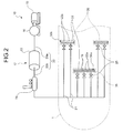
Fig. 2] Fig. 2 is an explanatory diagram of a configuration of the ship-body frictional resistance reducing device according to the embodiment. - [
Fig. 3] Fig. 3 is a perspective view schematically depicting a portion around a sea chest of the ship-body frictional resistance reducing device according to the embodiment. - [
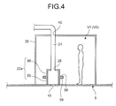
Fig. 4] Fig. 4 is a cross-sectional view of the sea chest according to the embodiment shown inFig. 3 , along a cutting plane A shown inFig. 3 . - [
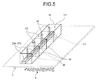
Fig. 5] Fig. 5 is a perspective view schematically depicting a portion around a sea chest of a ship-body frictional resistance reducing device according to a modification of the embodiment. -
- 1
- ship body
- 5
- ship's bottom
- 8
- air bubble curtain
- 10
- ship-body frictional resistance reducing device
- 15
- air ejection hole
- 16
- blower
- 17
- air supply path
- 20
- main supply pipe
- 21
- branch supply pipe
- 22
- air chamber
- 22a
- center air chamber
- 22b
- side air chamber
- 23
- primary air tank
- 24
- air flow meter
- 25
- on-off valve
- 28
- air supply port
- 30a
- center air-ejection hole group
- 30b
- side air-ejection hole group
- 35
- center sea chest
- 36
- side sea chest
- 40
- insertion port
- 45
- longitudinal
- 48
- intercommunicating through hole
- 50
- access room
- 51
- entryway
- 52
- access through hole
- 55
- lower casing
- 56
- upper casing
- 57
- lower flange
- 58
- upper flange
- V1
- working area
- V2
- divided working area
- Exemplary embodiments of a ship-body frictional resistance reducing device according to the present invention will be explained below in detail with reference to the accompanying drawings. The present invention is not limited to the embodiments. In addition, constituent elements in the following embodiments include those that can be easily replaceable by persons skilled in the art or that are substantially equivalent.
-
Fig. 1 is a side view schematically depicting a ship body having incorporated thereon a ship-body frictional resistance reducing device according to an embodiment of the present invention;Fig. 2 is an explanatory diagram of a configuration of the ship-body frictional resistance reducing device according to the present embodiment;Fig. 3 is a perspective view schematically depicting a portion around a sea chest of the ship-body frictional resistance reducing device according to the present embodiment;Fig. 4 is a cross-sectional view of the sea chest according to the present embodiment shown inFig. 3 , along a cutting plane A shown inFig. 3 ; andFig. 5 is a perspective view schematically depicting a portion around a sea chest of a ship-body frictional resistance reducing device according to a modification of the present embodiment. - A ship-body frictional
resistance reducing device 10 according to the present embodiment reduces the frictional resistance of asailing ship body 1 by forming an air bubble curtain 8 (seeFig. 3 ) on a ship'sbottom 5 by generating air bubbles from a plurality of air ejection holes 15 formed on the ship'sbottom 5. As shown inFig. 1 , theship body 1 having incorporated thereon the ship-body frictionalresistance reducing device 10 is, for example, a flat-bottomed ship in which the ship'sbottom 5 is flat, and the ship-body frictionalresistance reducing device 10 is arranged on a bow side of theship body 1. The ship-body frictionalresistance reducing device 10 is not limited to be applied to the flat-bottomed ship, but also can be applied to other types of ships. - The ship-body frictional
resistance reducing device 10 is explained with reference toFig. 1 andFig. 2 . The ship-body frictionalresistance reducing device 10 includes a large number of the air ejection holes 15 formed on the ship'sbottom 5, ablower 16 that can supply the air to the large number of the air ejection holes 15, and anair supply path 17 that connects theblower 16 and the large number of the air ejection holes 15. - The large number of the air ejection holes constitute air-
ejection hole groups ship body 1. The air-ejection hole groups bottom 5 more than one (for example, three in the present embodiment). One of the three air-ejection hole groups ejection hole groups ship body 1, and the pair of the side air-ejection hole groups ship body 1. - The
blower 16 is arranged on the bow side of theship body 1, functioning as an air supply source that can supply the air to the large number of the air ejection holes 15. Anelectric motor 19 is employed as a driving source for theblower 16, and an amount of supplying the air sent from theblower 16 can be controlled by controlling a rotation speed of theelectric motor 19. A distance between theblower 16 and the center air-ejection hole group 30a is shorter than a distance between theblower 16 and the side air-ejection hole groups blower 16 and the center air-ejection hole group 30a are arranged on the bow side of theship body 1. The air supply source is not limited to theblower 16, but can be an air compressor or the like. Furthermore, although the air supply source is configured with a single unit of theblower 16 in the present embodiment, the air supply source is not limited to this configuration, but also can be configured with a plurality ofblowers 16. - The
air supply path 17 includes amain supply pipe 20 of which one end is connected to theblower 16, a plurality ofbranch supply pipes 21 connected to themain supply pipe 20, and a plurality ofair chambers 22 respectively connected to thebranch supply pipes 21. Aprimary air tank 23 is provided on themain supply pipe 20. That is, themain supply pipe 20 is configured with an upstream-sidemain supply pipe 20a connecting theblower 16 and theprimary air tank 23 and a downstream-sidemain supply pipe 20b connecting theprimary air tank 23 and thebranch supply pipes 21. Anair flow meter 24 for measuring a flow rate of the air flowing through the downstream-sidemain supply pipe 20b is provided on the downstream-sidemain supply pipe 20b. An on-offvalve 25 for opening and closing a pipe is provided on each of thebranch supply pipes 21. - The
primary air tank 23 is configured to be able to store the air supplied from theblower 16 via the upstream-sidemain supply pipe 20a. By providing theprimary air tank 23 on themain supply pipe 20, it is possible to cope with a pressure change of the air (a so-called pulsation of the air) generated at theblower 16 and the upstream-sidemain supply pipe 20a. - The
air chambers 22 are formed in a box shape of a rectangular cuboid, being arranged corresponding to the air ejection holes 15 formed on the ship'sbottom 5. That is, the air ejection holes 15 are formed on a bottom surface of each of the air chambers 22 (that is, the ship's bottom). Furthermore, anair supply port 28 to which each of thebranch supply pipes 21 is connected is formed substantially at a center portion of a top wall surface of each of the air chambers 22 (seeFig. 4 ). Theair chambers 22 are configured with a plurality ofcenter air chambers 22a corresponding to the center air-ejection hole group 30a and a plurality ofside air chambers 22b corresponding to the pair of the side air-ejection hole groups - The
center air chambers 22a are formed in a box shape of a rectangular cuboid with its longitudinal direction aligned with the ship width direction, being arranged in the ship width direction. By supplying the air from theblower 16 to thecenter air chambers 22a, the air is ejected from the center air-ejection hole group 30a to generate the air bubbles. - The
side air chambers 22b are, in the same manner as thecenter air chambers 22a, formed in a box shape of a rectangular cuboid with its longitudinal direction aligned with the ship width direction, being arranged in the ship width direction. Theside air chambers 22b are divided into two portions corresponding to a pair of side air ejection holes 15. By supplying the air from theblower 16 to each of the dividedside air chambers 22b, the air is ejected from the side air-ejection hole groups - Although details are described later, on an outside of the plurality of
center air chambers 22a, acenter sea chest 35 is formed to cover them. On an outside of each of the plurality ofside air chambers 22b which is divided into two, a pair of side sea chests is formed to cover them. - The
air flow meter 24 measures, as described above, the flow rate of the air flowing through the downstream-sidemain supply pipe 20b. Based on a result of measurement of theair flow meter 24, an amount of supplying the air supplied from theblower 16 is controlled. - A plurality of on-off
valves 25 respectively provided on thebranch supply pipes 21 functions as a so-called check valve, which is installed for preventing an infiltration of seawater into theair supply path 17 on the upstream side from the on-offvalves 25. Specifically, when an operation of the ship-body frictionalresistance reducing device 10 is stopped, that is, when the driving of theblower 16 is stopped, the ejection of the air from each of the air ejection holes 15 is stopped. This causes the seawater to flow into each of theair chambers 22 via each of the air ejection holes 15. At this time, because each of theair chambers 22 interlocks with each of thebranch supply pipes 21, the infiltration of the seawater into each of thebranch supply pipes 21 on the upstream side from the on-offvalves 25 is prevented by closing the on-offvalves 25. - Therefore, when the
blower 16 is driven, the air blown out from theblower 16 flows into theprimary air tank 23 through the upstream-sidemain supply pipe 20a, and thereafter, the air flows into each of theair chambers 22 via the downstream-sidemain supply pipe 20b and thebranch supply pipes 21. At this time, the amount of supplying the air from theblower 16 is adjusted by controlling theelectric motor 19 based on the result of measurement of theair flow meter 24. When the air flows into each of theair chambers 22, it is ejected to underwater through each of the air ejection holes 15 to generate the air bubbles from the ship'sbottom 5. - The
sea chests air chambers 22, which are characteristic parts of the present invention, are explained below with reference toFig. 3 andFig. 4 . As described above, a plurality ofsea chests ejection hole groups center sea chest 35 that covers thecenter air chambers 22a and the pair of theside sea chests side air chambers 22b. Thecenter sea chest 35 and the pair of theside sea chests center sea chest 35 is mainly explained while explanations of the configuration of each the pair of theside sea chests - As shown in
Fig. 3 , thecenter sea chest 35 is formed in a box shape of a rectangular cuboid with its longitudinal direction aligned with the ship width direction, and is arranged on the ship'sbottom 5 inside theship body 1. With this arrangement, the longitudinal direction of thecenter sea chest 35, the arrangement direction of thecenter air chambers 22a, and the arrangement direction of the center air-ejection hole group 30a become the same direction. A space slightly larger than a worker is formed in thecenter sea chest 35 so that its inside serves as a working area V1 (seeFig. 4 ). Furthermore, thecenter sea chest 35 is configured in a watertight structure to prevent ingress of the sea water into theship body 1, and a connection portion between thecenter sea chest 35 and the ship'sbottom 5 is joined by, for example, welding or the like. In addition, a plurality ofinsertion ports 40 for inserting thebranch supply pipes 21 respectively connected to thecenter air chambers 22a are formed on a ceiling surface of thecenter sea chest 35 in a penetrating manner. - At this time, a plurality of
longitudinals 45 that extends in the ship length direction and is used as aggregates are arranged in parallel in the ship width direction in thecenter sea chest 35. Therefore, the inside of thecenter sea chest 35 is partitioned into the divided working areas V2 by thelongitudinals 45. That is, thelongitudinals 45 serve as a plurality of partitioning walls dividing the working area V1 in thecenter sea chest 35. - In each of the divided working areas V2 in the
center sea chest 35 partitioned by thelongitudinals 45, a part of thecenter air chambers 22a obtained by dividing the number of thecenter air chambers 22a by the number of the divided working areas V2 is arranged. Therefore, an intercommunicating throughhole 48 is formed on each of thelongitudinals 45 so that a worker can pass through each of the divided working areas V2 to perform maintenance of each of thecenter air chambers 22a arranged in each of the divided working areas V2. - At one side portion of the
center sea chest 35 in the ship width direction, anaccess room 50 is provided being adjacent to thecenter sea chest 35 at the stern side of the ship length direction. As thecenter sea chest 35, theaccess room 50 is formed in a box shape of a rectangular cuboid, and is arranged on the ship'sbottom 5 inside theship body 1. Furthermore, as thecenter sea chest 35, theaccess room 50 is configured in a watertight structure to prevent ingress of the sea water into theship body 1, and a connection portion between theaccess room 50 and the ship'sbottom 5 and a connection point between theaccess room 50 and thecenter sea chest 35 are joined by, for example, welding or the like. - On a bottom surface of the access room 50 (that is, the ship's bottom 5), an
entryway 51 for a worker to go in and out theaccess room 50 from outside the ship is formed in a penetrating manner, and an access throughhole 52 is formed on a wall between theaccess room 50 and thecenter sea chest 35. With this configuration, the worker can come and go to thecenter sea chest 35 from theaccess room 50 through the access throughhole 52. Therefore, theaccess room 50 serves as a passage that connects the entryway 51 and thecenter sea chest 35. A hatch made of a grating material or the like is provided on theentryway 51. - With this configuration, when a worker enters the
center sea chest 35 from outside the ship, the worker can enter theaccess room 50 through the entryway 51, and enter thecenter sea chest 35 from theaccess room 50 through the access throughhole 52. The worker entered thecenter sea chest 35 can come and go between the divided working areas V2 through the intercommunicating throughhole 48. - A part of the
center air chambers 22a arranged in each of the divided working areas V2 in the center sea chest 35 (one in the drawing) is explained below with reference toFig. 4 . Each of thecenter air chambers 22a arranged in each of the divided working areas V2 includes alower casing 55 arranged on the ship's bottom side and anupper casing 56 arranged on a shipboard side. - The
lower casing 55 is formed in a frame body having a cross section of a rectangular shape, being arrange to enclose the air ejection holes 15 formed on the ship'sbottom 5. A bottom portion of thelower casing 55 and the ship'sbottom 5 are joined with each other by welding or the like. In addition, a lower flange 57 that protrudes outward from thelower casing 55 is formed at an upper portion of thelower casing 55. - The
upper casing 56 is formed in a box shape having a cross section of a rectangular shape with a lower surface opened, being arranged to couple with thelower casing 55. Anupper flange 58 that protrudes outward from theupper casing 56 is formed at a lower portion of theupper casing 56. With this configuration, because the lower flange 57 and theupper flange 58 are coupled with each other, by fixing the lower flange 57 and theupper flange 58 with a bolt, theupper casing 56 can be fixed to thelower casing 55. Likewise, by removing this bolt, it is possible to detach theupper casing 56 from thelower casing 55. Anair supply port 28 to which thebranch supply pipe 21 is connected is formed on a ceiling surface of theupper casing 56. - Therefore, by detaching the
upper casing 56 from thelower casing 55, the worker can perform application of an anticorrosion material or removal of the ocean species inside each of thecenter air chambers 22a, that is, inside theupper casing 56 and thelower casing 55. - As described above, the pair of the
side sea chests 36 has the same configuration as thecenter sea chest 35, and the pair of theside air chambers 22b has the same configuration as thecenter air chambers 22a. - With the above configuration, it is possible to configure each of the
sea chests sea chests air chambers ship body 1, and at the same time, it is possible to perform the maintenance of each of theair chambers - Even though the inside of each of the
sea chests longitudinals 45 into the divided working areas V2, forming the intercommunicating throughhole 48 on each of thelongitudinals 45 makes it possible to come and go to the divided working areas V2. With this configuration, it is possible to perform the maintenance of each of theair chambers - Furthermore, by forming the entryway 51 on the ship's
bottom 5 and providing theaccess room 50, it is possible to access the inside of each of thesea chests access room 50. At this time, because the intercommunicating throughhole 48 is formed on each of thelongitudinals 45, it is sufficient to form a single unit of the entryway 51 to access thesea chests sea chests entryways 51. - Moreover, because the
upper casing 56 can be coupled with thelower casing 55 of each of theair chambers air chambers - Although it is configured that the
access room 50 is provided adjacent to thecenter sea chest 35 and theentryway 51 is formed on theaccess room 50 to access thecenter sea chest 35 according to the present embodiment, the configuration is not limited to this method. As shown inFig. 5 , the entryway 51 can be formed in thecenter sea chest 35 by removing theaccess room 50. With this configuration, because it is not necessary to arrange theaccess room 50, it is possible to constitute the configuration of the ship-body frictionalresistance reducing device 10 simple. - As described above, the ship-body frictional resistance reducing device according to the present invention is useful for a ship-body frictional resistance reducing device having a plurality of air ejection holes formed on a ship's bottom and particularly useful when maintenance of an air chamber is performed.
Claims (4)
- A ship-body frictional resistance reducing device for reducing frictional resistance of a sailing ship body by forming an air bubble curtain on a ship's bottom by generating air bubbles, the ship-body frictional resistance reducing device comprising:an air chamber provided on the ship's bottom inside the ship body;a plurality of air ejection holes formed in an arrayed manner on the ship's bottom that becomes a bottom portion of the air chamber; anda sea chest provided on the ship's bottom inside the ship body in a manner such that the sea chest covers the air chamber.
- The ship-body frictional resistance reducing device according to claim 1, wherein
a partition wall for partitioning an inside space is provided in the sea chest, and
a through hole is formed on the partitioning wall. - The ship-body frictional resistance reducing device according to claim 2, further comprising:an entryway formed on the ship's bottom; anda passage that connects the entryway and an inside of the sea chest.
- The ship-body frictional resistance reducing device according to any one of claims 1 to 3, wherein
the air chamber includes a lower casing arranged on the ship's bottom side and an upper casing arranged on a shipboard side, and
the upper casing is configured to be coupled with the lower casing in a detachable manner.
Applications Claiming Priority (2)
| Application Number | Priority Date | Filing Date | Title |
|---|---|---|---|
| JP2008298730A JP5022346B2 (en) | 2008-11-21 | 2008-11-21 | Hull frictional resistance reduction device |
| PCT/JP2009/052570 WO2010058612A1 (en) | 2008-11-21 | 2009-02-16 | Hull frictional resistance reducing device |
Publications (3)
| Publication Number | Publication Date |
|---|---|
| EP2351686A1 true EP2351686A1 (en) | 2011-08-03 |
| EP2351686A4 EP2351686A4 (en) | 2013-05-01 |
| EP2351686B1 EP2351686B1 (en) | 2016-05-04 |
Family
ID=42198054
Family Applications (1)
| Application Number | Title | Priority Date | Filing Date |
|---|---|---|---|
| EP09827393.1A Not-in-force EP2351686B1 (en) | 2008-11-21 | 2009-02-16 | Hull frictional resistance reducing device |
Country Status (6)
| Country | Link |
|---|---|
| US (1) | US8516970B2 (en) |
| EP (1) | EP2351686B1 (en) |
| JP (1) | JP5022346B2 (en) |
| KR (1) | KR101278754B1 (en) |
| CN (1) | CN102224064B (en) |
| WO (1) | WO2010058612A1 (en) |
Families Citing this family (22)
| Publication number | Priority date | Publication date | Assignee | Title |
|---|---|---|---|---|
| EP2487218A1 (en) * | 2011-02-09 | 2012-08-15 | Koninklijke Philips Electronics N.V. | Polymeric matrix with organic phosphor and manufactory thereof |
| JP5695952B2 (en) * | 2011-03-31 | 2015-04-08 | 三菱重工業株式会社 | Manufacturing method of ship with reduced frictional resistance |
| JP5087161B1 (en) * | 2011-08-29 | 2012-11-28 | 三菱重工業株式会社 | Ship and ship maintenance inspection method |
| NO335909B1 (en) * | 2012-06-14 | 2015-03-23 | Nader Hassavari | Procedure for air-driven propulsion of a vessel and air-driven vessel |
| JP6049443B2 (en) * | 2012-12-25 | 2016-12-21 | 三菱重工業株式会社 | Friction resistance reduction type ship |
| KR20160144365A (en) * | 2014-03-05 | 2016-12-16 | 실버스트림 테크놀러지스 비.브이. | Use of an air lubrication system for reducing marine growth on a vessel |
| KR101616325B1 (en) * | 2014-05-30 | 2016-04-28 | 삼성중공업 주식회사 | Air Injection Apparatus for Test of Ship and Ship Model Having The Same |
| US10266230B2 (en) | 2015-06-29 | 2019-04-23 | Samsung Heavy Industries Co., Ltd. | Frictional resistance-reducing device and ship including same |
| CN105539770A (en) * | 2015-12-04 | 2016-05-04 | 深圳市易特科信息技术有限公司 | Rescue diving apparatus and method for sea rescue |
| EP3290324A1 (en) * | 2016-08-30 | 2018-03-07 | Silverstream Technologies B.V. | Dual cavity air lubrication system |
| CN108001610B (en) * | 2017-11-23 | 2024-04-23 | 中船(上海)节能技术有限公司 | Gas lubrication drag reduction and energy saving device |
| CN108177724A (en) * | 2018-01-12 | 2018-06-19 | 中船重工船舶设计研究中心有限公司 | A kind of voltage stabilizing cavity configuration and installation method for resistance reduction by air cavity technology |
| CN108674575B (en) * | 2018-05-23 | 2020-10-27 | 南京理工大学 | A fluid drag reduction device |
| JP7227728B2 (en) * | 2018-10-10 | 2023-02-22 | 三菱造船株式会社 | How to use existing ships |
| KR102652787B1 (en) * | 2019-08-30 | 2024-03-29 | 삼성중공업 주식회사 | Air lubrication system of ship |
| KR102652786B1 (en) * | 2019-08-30 | 2024-03-29 | 삼성중공업 주식회사 | Air lubrication system of ship |
| CN111361684A (en) * | 2020-03-20 | 2020-07-03 | 中国船舶工业集团公司第七0八研究所 | A ship drag reduction and auxiliary ice breaking bubble system |
| KR20220040716A (en) | 2020-09-24 | 2022-03-31 | 삼성중공업 주식회사 | Ship |
| CN112810748A (en) * | 2021-02-23 | 2021-05-18 | 中船重工(上海)节能技术发展有限公司 | Corrosion-resistant pressure stabilizing cavity structure suitable for gas layer drag reduction ship |
| CN113788102A (en) * | 2021-10-19 | 2021-12-14 | 中船重工(上海)节能技术发展有限公司 | Voltage stabilization cavity structure, gas layer resistance reduction system and ship |
| CN114889742B (en) * | 2022-05-09 | 2023-03-14 | 江苏科技大学 | Marine damping device that ventilates |
| CN119611607B (en) * | 2024-12-09 | 2026-01-02 | 浙江大学 | A self-starting and stopping antifouling bubble generating device, method, and ship containing the device |
Family Cites Families (17)
| Publication number | Priority date | Publication date | Assignee | Title |
|---|---|---|---|---|
| JPS6133389A (en) * | 1984-07-25 | 1986-02-17 | Nippon Kokan Kk <Nkk> | Double bottom tank test method |
| US4840589A (en) * | 1986-09-12 | 1989-06-20 | Breaux Vance V | Underwater exhaust system for boats of stepped-hull construction and including exhaust cooling |
| JPH03120019A (en) | 1989-10-03 | 1991-05-22 | Inax Corp | Manufacture of counter made of resin |
| JPH03120019U (en) * | 1990-03-23 | 1991-12-10 | ||
| JP3120019B2 (en) | 1995-05-29 | 2000-12-25 | デンヨー株式会社 | Assembly structure of permanent magnet generator |
| WO1997020728A1 (en) * | 1995-12-04 | 1997-06-12 | Ishikawajima-Harima Heavy Industries Co., Ltd. | Method of reducing friction resistance of hull, ship whose friction resistance is reduced by the method, and method of analyzing jetted bubbles on ship |
| JPH1029586A (en) * | 1996-07-12 | 1998-02-03 | Ishikawajima Harima Heavy Ind Co Ltd | Installation method of air blower for generating small air bubbles in ship with reduced frictional resistance |
| JPH1095389A (en) * | 1996-09-24 | 1998-04-14 | Ishikawajima Harima Heavy Ind Co Ltd | Ship friction reduction device |
| JPH10100984A (en) * | 1996-09-27 | 1998-04-21 | Ishikawajima Harima Heavy Ind Co Ltd | Ship friction reduction device |
| JPH11227675A (en) * | 1998-02-13 | 1999-08-24 | Ishikawajima Harima Heavy Ind Co Ltd | Air blower for ship with reduced frictional resistance |
| JPH11222180A (en) | 1998-02-04 | 1999-08-17 | Ishikawajima Harima Heavy Ind Co Ltd | Ship friction reduction device |
| CA2244615A1 (en) * | 1997-08-22 | 1999-02-22 | Ishikawajima-Harima Heavy Industries Co., Ltd. | Friction-reducing ship with compressed air generation apparatus, friction reduction apparatus and gas jetting device |
| JPH1159563A (en) * | 1997-08-22 | 1999-03-02 | Ishikawajima Harima Heavy Ind Co Ltd | Friction reducing ship and air generator |
| US6145459A (en) * | 1997-12-19 | 2000-11-14 | Ishikawajima-Harima Heavy Industries Co., Ltd. | Friction-reducing ship and method for reducing skin friction |
| JPH11180382A (en) * | 1997-12-22 | 1999-07-06 | Ishigaki:Kk | Diver diving equipment on a diving boat |
| JP4151681B2 (en) | 2005-07-19 | 2008-09-17 | 株式会社日立製作所 | Fine bubble generating apparatus and method |
| JP2008149209A (en) * | 2006-12-14 | 2008-07-03 | Marcom:Kk | Microbubble generator and microbubble supply system |
-
2008
- 2008-11-21 JP JP2008298730A patent/JP5022346B2/en active Active
-
2009
- 2009-02-16 WO PCT/JP2009/052570 patent/WO2010058612A1/en not_active Ceased
- 2009-02-16 KR KR1020117010771A patent/KR101278754B1/en not_active Expired - Fee Related
- 2009-02-16 EP EP09827393.1A patent/EP2351686B1/en not_active Not-in-force
- 2009-02-16 US US13/128,959 patent/US8516970B2/en not_active Expired - Fee Related
- 2009-02-16 CN CN200980146462.1A patent/CN102224064B/en not_active Expired - Fee Related
Also Published As
| Publication number | Publication date |
|---|---|
| KR20110079837A (en) | 2011-07-08 |
| JP5022346B2 (en) | 2012-09-12 |
| JP2010120610A (en) | 2010-06-03 |
| EP2351686B1 (en) | 2016-05-04 |
| US20110220002A1 (en) | 2011-09-15 |
| WO2010058612A1 (en) | 2010-05-27 |
| EP2351686A4 (en) | 2013-05-01 |
| CN102224064A (en) | 2011-10-19 |
| CN102224064B (en) | 2014-08-13 |
| KR101278754B1 (en) | 2013-06-25 |
| US8516970B2 (en) | 2013-08-27 |
Similar Documents
| Publication | Publication Date | Title |
|---|---|---|
| EP2351686B1 (en) | Hull frictional resistance reducing device | |
| CN102448807B (en) | Drag reducing devices for ships | |
| EP2353992A1 (en) | Device for reducing frictional resistance of ship body | |
| CN104755369B (en) | Ships with reduced frictional resistance | |
| US8561562B2 (en) | Device for reducing frictional resistance of ship body | |
| KR19990023663A (en) | Friction Reducing Ships with Compressed Air Generator, Friction Reduction Device and Gas Blowing Device | |
| JP5138804B1 (en) | Ship | |
| JP2023106751A (en) | vessel | |
| JP2012076643A (en) | Gas recovery device and frictional resistance reducing type ship | |
| KR20130003927A (en) | Overboard sea chest | |
| KR20120000300A (en) | Noise-reducing vessel | |
| JP2014227089A (en) | Ship remodeling method and frictional resistance reduction ship | |
| JP6413176B2 (en) | Ship | |
| JP6655564B2 (en) | Ship friction reduction device | |
| JP6143165B2 (en) | Ship frictional resistance reduction device | |
| JPH10100984A (en) | Ship friction reduction device | |
| JP6071546B2 (en) | Friction resistance reduction type ship | |
| JPH09328095A (en) | Air blower cleaning device for micro air bubble generation on ships | |
| JP5087161B1 (en) | Ship and ship maintenance inspection method | |
| JP2012066745A (en) | Frictional resistance alleviating apparatus for ship and method of preventing marine creatures from sticking to frictional resistance alleviating apparatus for ship | |
| KR101731020B1 (en) | Sealable hausimg for submerged ship and submerged ship having the same | |
| JP2014125032A (en) | Frictional resistance reducing type vessel | |
| JP5754905B2 (en) | Ship frictional resistance reducing device and marine organism adhesion preventing method for ship frictional resistance reducing device | |
| WO2001066410A1 (en) | Frictional resistance reducing method, and ship with reduced frictional resistance | |
| KR20110136954A (en) | Noise-reducing vessel |
Legal Events
| Date | Code | Title | Description |
|---|---|---|---|
| PUAI | Public reference made under article 153(3) epc to a published international application that has entered the european phase |
Free format text: ORIGINAL CODE: 0009012 |
|
| 17P | Request for examination filed |
Effective date: 20110518 |
|
| AK | Designated contracting states |
Kind code of ref document: A1 Designated state(s): AT BE BG CH CY CZ DE DK EE ES FI FR GB GR HR HU IE IS IT LI LT LU LV MC MK MT NL NO PL PT RO SE SI SK TR |
|
| RIN1 | Information on inventor provided before grant (corrected) |
Inventor name: KAMEYAMA, SHOICHI Inventor name: HIGASA, SEJIRO Inventor name: TAKANO, SHINICHI Inventor name: MINE, TAKASHI Inventor name: MIZOKAMI, SHUJI |
|
| DAX | Request for extension of the european patent (deleted) | ||
| A4 | Supplementary search report drawn up and despatched |
Effective date: 20130405 |
|
| RIC1 | Information provided on ipc code assigned before grant |
Ipc: B63B 1/38 20060101AFI20130328BHEP |
|
| 17Q | First examination report despatched |
Effective date: 20150129 |
|
| GRAP | Despatch of communication of intention to grant a patent |
Free format text: ORIGINAL CODE: EPIDOSNIGR1 |
|
| INTG | Intention to grant announced |
Effective date: 20151204 |
|
| GRAS | Grant fee paid |
Free format text: ORIGINAL CODE: EPIDOSNIGR3 |
|
| GRAA | (expected) grant |
Free format text: ORIGINAL CODE: 0009210 |
|
| RIN1 | Information on inventor provided before grant (corrected) |
Inventor name: MIZOKAMI, SHUJI Inventor name: MINE, TAKASHI Inventor name: TAKANO, SHINICHI Inventor name: KAMEYAMA, SHOICHI Inventor name: HIGASA, SEIJIRO |
|
| AK | Designated contracting states |
Kind code of ref document: B1 Designated state(s): AT BE BG CH CY CZ DE DK EE ES FI FR GB GR HR HU IE IS IT LI LT LU LV MC MK MT NL NO PL PT RO SE SI SK TR |
|
| REG | Reference to a national code |
Ref country code: GB Ref legal event code: FG4D |
|
| REG | Reference to a national code |
Ref country code: CH Ref legal event code: EP |
|
| REG | Reference to a national code |
Ref country code: AT Ref legal event code: REF Ref document number: 796655 Country of ref document: AT Kind code of ref document: T Effective date: 20160515 |
|
| REG | Reference to a national code |
Ref country code: IE Ref legal event code: FG4D |
|
| REG | Reference to a national code |
Ref country code: DE Ref legal event code: R096 Ref document number: 602009038504 Country of ref document: DE |
|
| REG | Reference to a national code |
Ref country code: NL Ref legal event code: MP Effective date: 20160504 |
|
| REG | Reference to a national code |
Ref country code: LT Ref legal event code: MG4D |
|
| PG25 | Lapsed in a contracting state [announced via postgrant information from national office to epo] |
Ref country code: LT Free format text: LAPSE BECAUSE OF FAILURE TO SUBMIT A TRANSLATION OF THE DESCRIPTION OR TO PAY THE FEE WITHIN THE PRESCRIBED TIME-LIMIT Effective date: 20160504 Ref country code: NL Free format text: LAPSE BECAUSE OF FAILURE TO SUBMIT A TRANSLATION OF THE DESCRIPTION OR TO PAY THE FEE WITHIN THE PRESCRIBED TIME-LIMIT Effective date: 20160504 Ref country code: NO Free format text: LAPSE BECAUSE OF FAILURE TO SUBMIT A TRANSLATION OF THE DESCRIPTION OR TO PAY THE FEE WITHIN THE PRESCRIBED TIME-LIMIT Effective date: 20160804 |
|
| REG | Reference to a national code |
Ref country code: AT Ref legal event code: MK05 Ref document number: 796655 Country of ref document: AT Kind code of ref document: T Effective date: 20160504 |
|
| PG25 | Lapsed in a contracting state [announced via postgrant information from national office to epo] |
Ref country code: LV Free format text: LAPSE BECAUSE OF FAILURE TO SUBMIT A TRANSLATION OF THE DESCRIPTION OR TO PAY THE FEE WITHIN THE PRESCRIBED TIME-LIMIT Effective date: 20160504 Ref country code: ES Free format text: LAPSE BECAUSE OF FAILURE TO SUBMIT A TRANSLATION OF THE DESCRIPTION OR TO PAY THE FEE WITHIN THE PRESCRIBED TIME-LIMIT Effective date: 20160504 Ref country code: PT Free format text: LAPSE BECAUSE OF FAILURE TO SUBMIT A TRANSLATION OF THE DESCRIPTION OR TO PAY THE FEE WITHIN THE PRESCRIBED TIME-LIMIT Effective date: 20160905 Ref country code: SE Free format text: LAPSE BECAUSE OF FAILURE TO SUBMIT A TRANSLATION OF THE DESCRIPTION OR TO PAY THE FEE WITHIN THE PRESCRIBED TIME-LIMIT Effective date: 20160504 Ref country code: HR Free format text: LAPSE BECAUSE OF FAILURE TO SUBMIT A TRANSLATION OF THE DESCRIPTION OR TO PAY THE FEE WITHIN THE PRESCRIBED TIME-LIMIT Effective date: 20160504 Ref country code: GR Free format text: LAPSE BECAUSE OF FAILURE TO SUBMIT A TRANSLATION OF THE DESCRIPTION OR TO PAY THE FEE WITHIN THE PRESCRIBED TIME-LIMIT Effective date: 20160805 |
|
| PG25 | Lapsed in a contracting state [announced via postgrant information from national office to epo] |
Ref country code: EE Free format text: LAPSE BECAUSE OF FAILURE TO SUBMIT A TRANSLATION OF THE DESCRIPTION OR TO PAY THE FEE WITHIN THE PRESCRIBED TIME-LIMIT Effective date: 20160504 Ref country code: SK Free format text: LAPSE BECAUSE OF FAILURE TO SUBMIT A TRANSLATION OF THE DESCRIPTION OR TO PAY THE FEE WITHIN THE PRESCRIBED TIME-LIMIT Effective date: 20160504 Ref country code: CZ Free format text: LAPSE BECAUSE OF FAILURE TO SUBMIT A TRANSLATION OF THE DESCRIPTION OR TO PAY THE FEE WITHIN THE PRESCRIBED TIME-LIMIT Effective date: 20160504 Ref country code: DK Free format text: LAPSE BECAUSE OF FAILURE TO SUBMIT A TRANSLATION OF THE DESCRIPTION OR TO PAY THE FEE WITHIN THE PRESCRIBED TIME-LIMIT Effective date: 20160504 Ref country code: RO Free format text: LAPSE BECAUSE OF FAILURE TO SUBMIT A TRANSLATION OF THE DESCRIPTION OR TO PAY THE FEE WITHIN THE PRESCRIBED TIME-LIMIT Effective date: 20160504 |
|
| REG | Reference to a national code |
Ref country code: DE Ref legal event code: R097 Ref document number: 602009038504 Country of ref document: DE |
|
| PG25 | Lapsed in a contracting state [announced via postgrant information from national office to epo] |
Ref country code: BE Free format text: LAPSE BECAUSE OF FAILURE TO SUBMIT A TRANSLATION OF THE DESCRIPTION OR TO PAY THE FEE WITHIN THE PRESCRIBED TIME-LIMIT Effective date: 20160504 Ref country code: PL Free format text: LAPSE BECAUSE OF FAILURE TO SUBMIT A TRANSLATION OF THE DESCRIPTION OR TO PAY THE FEE WITHIN THE PRESCRIBED TIME-LIMIT Effective date: 20160504 Ref country code: AT Free format text: LAPSE BECAUSE OF FAILURE TO SUBMIT A TRANSLATION OF THE DESCRIPTION OR TO PAY THE FEE WITHIN THE PRESCRIBED TIME-LIMIT Effective date: 20160504 |
|
| PLBE | No opposition filed within time limit |
Free format text: ORIGINAL CODE: 0009261 |
|
| STAA | Information on the status of an ep patent application or granted ep patent |
Free format text: STATUS: NO OPPOSITION FILED WITHIN TIME LIMIT |
|
| 26N | No opposition filed |
Effective date: 20170207 |
|
| PG25 | Lapsed in a contracting state [announced via postgrant information from national office to epo] |
Ref country code: SI Free format text: LAPSE BECAUSE OF FAILURE TO SUBMIT A TRANSLATION OF THE DESCRIPTION OR TO PAY THE FEE WITHIN THE PRESCRIBED TIME-LIMIT Effective date: 20160504 |
|
| PG25 | Lapsed in a contracting state [announced via postgrant information from national office to epo] |
Ref country code: MC Free format text: LAPSE BECAUSE OF FAILURE TO SUBMIT A TRANSLATION OF THE DESCRIPTION OR TO PAY THE FEE WITHIN THE PRESCRIBED TIME-LIMIT Effective date: 20160504 |
|
| REG | Reference to a national code |
Ref country code: CH Ref legal event code: PL |
|
| PG25 | Lapsed in a contracting state [announced via postgrant information from national office to epo] |
Ref country code: CH Free format text: LAPSE BECAUSE OF NON-PAYMENT OF DUE FEES Effective date: 20170228 Ref country code: LI Free format text: LAPSE BECAUSE OF NON-PAYMENT OF DUE FEES Effective date: 20170228 |
|
| REG | Reference to a national code |
Ref country code: IE Ref legal event code: MM4A |
|
| REG | Reference to a national code |
Ref country code: FR Ref legal event code: ST Effective date: 20171031 |
|
| PG25 | Lapsed in a contracting state [announced via postgrant information from national office to epo] |
Ref country code: LU Free format text: LAPSE BECAUSE OF NON-PAYMENT OF DUE FEES Effective date: 20170216 |
|
| PG25 | Lapsed in a contracting state [announced via postgrant information from national office to epo] |
Ref country code: FR Free format text: LAPSE BECAUSE OF NON-PAYMENT OF DUE FEES Effective date: 20170228 |
|
| PG25 | Lapsed in a contracting state [announced via postgrant information from national office to epo] |
Ref country code: IE Free format text: LAPSE BECAUSE OF NON-PAYMENT OF DUE FEES Effective date: 20170216 |
|
| REG | Reference to a national code |
Ref country code: DE Ref legal event code: R082 Ref document number: 602009038504 Country of ref document: DE Representative=s name: HENKEL & PARTNER MBB PATENTANWALTSKANZLEI, REC, DE Ref country code: DE Ref legal event code: R082 Ref document number: 602009038504 Country of ref document: DE Representative=s name: PATENTANWAELTE HENKEL, BREUER & PARTNER MBB, DE Ref country code: DE Ref legal event code: R081 Ref document number: 602009038504 Country of ref document: DE Owner name: MITSUBISHI SHIPBUILDING CO., LTD., YOKOHAMA-SH, JP Free format text: FORMER OWNER: MITSUBISHI HEAVY INDUSTRIES, LTD., TOKYO, JP |
|
| REG | Reference to a national code |
Ref country code: GB Ref legal event code: 732E Free format text: REGISTERED BETWEEN 20180809 AND 20180815 |
|
| PG25 | Lapsed in a contracting state [announced via postgrant information from national office to epo] |
Ref country code: MT Free format text: LAPSE BECAUSE OF NON-PAYMENT OF DUE FEES Effective date: 20170216 |
|
| PGFP | Annual fee paid to national office [announced via postgrant information from national office to epo] |
Ref country code: IT Payment date: 20190221 Year of fee payment: 11 Ref country code: GB Payment date: 20190213 Year of fee payment: 11 Ref country code: FI Payment date: 20190211 Year of fee payment: 11 Ref country code: DE Payment date: 20190205 Year of fee payment: 11 |
|
| PG25 | Lapsed in a contracting state [announced via postgrant information from national office to epo] |
Ref country code: HU Free format text: LAPSE BECAUSE OF FAILURE TO SUBMIT A TRANSLATION OF THE DESCRIPTION OR TO PAY THE FEE WITHIN THE PRESCRIBED TIME-LIMIT; INVALID AB INITIO Effective date: 20090216 |
|
| PG25 | Lapsed in a contracting state [announced via postgrant information from national office to epo] |
Ref country code: BG Free format text: LAPSE BECAUSE OF FAILURE TO SUBMIT A TRANSLATION OF THE DESCRIPTION OR TO PAY THE FEE WITHIN THE PRESCRIBED TIME-LIMIT Effective date: 20160504 |
|
| PG25 | Lapsed in a contracting state [announced via postgrant information from national office to epo] |
Ref country code: CY Free format text: LAPSE BECAUSE OF NON-PAYMENT OF DUE FEES Effective date: 20160504 |
|
| PG25 | Lapsed in a contracting state [announced via postgrant information from national office to epo] |
Ref country code: MK Free format text: LAPSE BECAUSE OF FAILURE TO SUBMIT A TRANSLATION OF THE DESCRIPTION OR TO PAY THE FEE WITHIN THE PRESCRIBED TIME-LIMIT Effective date: 20160504 |
|
| PG25 | Lapsed in a contracting state [announced via postgrant information from national office to epo] |
Ref country code: TR Free format text: LAPSE BECAUSE OF FAILURE TO SUBMIT A TRANSLATION OF THE DESCRIPTION OR TO PAY THE FEE WITHIN THE PRESCRIBED TIME-LIMIT Effective date: 20160504 |
|
| PG25 | Lapsed in a contracting state [announced via postgrant information from national office to epo] |
Ref country code: IS Free format text: LAPSE BECAUSE OF FAILURE TO SUBMIT A TRANSLATION OF THE DESCRIPTION OR TO PAY THE FEE WITHIN THE PRESCRIBED TIME-LIMIT Effective date: 20160904 |
|
| REG | Reference to a national code |
Ref country code: DE Ref legal event code: R119 Ref document number: 602009038504 Country of ref document: DE |
|
| REG | Reference to a national code |
Ref country code: FI Ref legal event code: MAE |
|
| GBPC | Gb: european patent ceased through non-payment of renewal fee |
Effective date: 20200216 |
|
| PG25 | Lapsed in a contracting state [announced via postgrant information from national office to epo] |
Ref country code: FI Free format text: LAPSE BECAUSE OF NON-PAYMENT OF DUE FEES Effective date: 20200216 |
|
| PG25 | Lapsed in a contracting state [announced via postgrant information from national office to epo] |
Ref country code: GB Free format text: LAPSE BECAUSE OF NON-PAYMENT OF DUE FEES Effective date: 20200216 Ref country code: DE Free format text: LAPSE BECAUSE OF NON-PAYMENT OF DUE FEES Effective date: 20200901 |
|
| PG25 | Lapsed in a contracting state [announced via postgrant information from national office to epo] |
Ref country code: IT Free format text: LAPSE BECAUSE OF NON-PAYMENT OF DUE FEES Effective date: 20200216 |