EP2351618A1 - Coated web manufacturing machine and manufacturing method - Google Patents
Coated web manufacturing machine and manufacturing method Download PDFInfo
- Publication number
- EP2351618A1 EP2351618A1 EP09823522A EP09823522A EP2351618A1 EP 2351618 A1 EP2351618 A1 EP 2351618A1 EP 09823522 A EP09823522 A EP 09823522A EP 09823522 A EP09823522 A EP 09823522A EP 2351618 A1 EP2351618 A1 EP 2351618A1
- Authority
- EP
- European Patent Office
- Prior art keywords
- web
- coating
- travel path
- applicator
- manufacturing machine
- Prior art date
- Legal status (The legal status is an assumption and is not a legal conclusion. Google has not performed a legal analysis and makes no representation as to the accuracy of the status listed.)
- Granted
Links
Images

Classifications
-
- B—PERFORMING OPERATIONS; TRANSPORTING
- B05—SPRAYING OR ATOMISING IN GENERAL; APPLYING FLUENT MATERIALS TO SURFACES, IN GENERAL
- B05C—APPARATUS FOR APPLYING FLUENT MATERIALS TO SURFACES, IN GENERAL
- B05C1/00—Apparatus in which liquid or other fluent material is applied to the surface of the work by contact with a member carrying the liquid or other fluent material, e.g. a porous member loaded with a liquid to be applied as a coating
- B05C1/04—Apparatus in which liquid or other fluent material is applied to the surface of the work by contact with a member carrying the liquid or other fluent material, e.g. a porous member loaded with a liquid to be applied as a coating for applying liquid or other fluent material to work of indefinite length
- B05C1/08—Apparatus in which liquid or other fluent material is applied to the surface of the work by contact with a member carrying the liquid or other fluent material, e.g. a porous member loaded with a liquid to be applied as a coating for applying liquid or other fluent material to work of indefinite length using a roller or other rotating member which contacts the work along a generating line
- B05C1/0826—Apparatus in which liquid or other fluent material is applied to the surface of the work by contact with a member carrying the liquid or other fluent material, e.g. a porous member loaded with a liquid to be applied as a coating for applying liquid or other fluent material to work of indefinite length using a roller or other rotating member which contacts the work along a generating line the work being a web or sheets
-
- A—HUMAN NECESSITIES
- A24—TOBACCO; CIGARS; CIGARETTES; SIMULATED SMOKING DEVICES; SMOKERS' REQUISITES
- A24C—MACHINES FOR MAKING CIGARS OR CIGARETTES
- A24C5/00—Making cigarettes; Making tipping materials for, or attaching filters or mouthpieces to, cigars or cigarettes
- A24C5/005—Treatment of cigarette paper
-
- A—HUMAN NECESSITIES
- A24—TOBACCO; CIGARS; CIGARETTES; SIMULATED SMOKING DEVICES; SMOKERS' REQUISITES
- A24D—CIGARS; CIGARETTES; TOBACCO SMOKE FILTERS; MOUTHPIECES OF CIGARS OR CIGARETTES; MANUFACTURE OF TOBACCO SMOKE FILTERS OR MOUTHPIECES
- A24D1/00—Cigars; Cigarettes
- A24D1/02—Cigars; Cigarettes with special covers
- A24D1/025—Cigars; Cigarettes with special covers the covers having material applied to defined areas, e.g. bands for reducing the ignition propensity
-
- B—PERFORMING OPERATIONS; TRANSPORTING
- B05—SPRAYING OR ATOMISING IN GENERAL; APPLYING FLUENT MATERIALS TO SURFACES, IN GENERAL
- B05C—APPARATUS FOR APPLYING FLUENT MATERIALS TO SURFACES, IN GENERAL
- B05C1/00—Apparatus in which liquid or other fluent material is applied to the surface of the work by contact with a member carrying the liquid or other fluent material, e.g. a porous member loaded with a liquid to be applied as a coating
- B05C1/04—Apparatus in which liquid or other fluent material is applied to the surface of the work by contact with a member carrying the liquid or other fluent material, e.g. a porous member loaded with a liquid to be applied as a coating for applying liquid or other fluent material to work of indefinite length
- B05C1/16—Apparatus in which liquid or other fluent material is applied to the surface of the work by contact with a member carrying the liquid or other fluent material, e.g. a porous member loaded with a liquid to be applied as a coating for applying liquid or other fluent material to work of indefinite length only at particular parts of the work
- B05C1/165—Apparatus in which liquid or other fluent material is applied to the surface of the work by contact with a member carrying the liquid or other fluent material, e.g. a porous member loaded with a liquid to be applied as a coating for applying liquid or other fluent material to work of indefinite length only at particular parts of the work using a roller or other rotating member which contacts the work along a generating line
-
- D—TEXTILES; PAPER
- D21—PAPER-MAKING; PRODUCTION OF CELLULOSE
- D21H—PULP COMPOSITIONS; PREPARATION THEREOF NOT COVERED BY SUBCLASSES D21C OR D21D; IMPREGNATING OR COATING OF PAPER; TREATMENT OF FINISHED PAPER NOT COVERED BY CLASS B31 OR SUBCLASS D21G; PAPER NOT OTHERWISE PROVIDED FOR
- D21H23/00—Processes or apparatus for adding material to the pulp or to the paper
- D21H23/02—Processes or apparatus for adding material to the pulp or to the paper characterised by the manner in which substances are added
- D21H23/22—Addition to the formed paper
- D21H23/52—Addition to the formed paper by contacting paper with a device carrying the material
- D21H23/56—Rolls
-
- B—PERFORMING OPERATIONS; TRANSPORTING
- B05—SPRAYING OR ATOMISING IN GENERAL; APPLYING FLUENT MATERIALS TO SURFACES, IN GENERAL
- B05C—APPARATUS FOR APPLYING FLUENT MATERIALS TO SURFACES, IN GENERAL
- B05C1/00—Apparatus in which liquid or other fluent material is applied to the surface of the work by contact with a member carrying the liquid or other fluent material, e.g. a porous member loaded with a liquid to be applied as a coating
- B05C1/04—Apparatus in which liquid or other fluent material is applied to the surface of the work by contact with a member carrying the liquid or other fluent material, e.g. a porous member loaded with a liquid to be applied as a coating for applying liquid or other fluent material to work of indefinite length
- B05C1/08—Apparatus in which liquid or other fluent material is applied to the surface of the work by contact with a member carrying the liquid or other fluent material, e.g. a porous member loaded with a liquid to be applied as a coating for applying liquid or other fluent material to work of indefinite length using a roller or other rotating member which contacts the work along a generating line
- B05C1/10—Apparatus in which liquid or other fluent material is applied to the surface of the work by contact with a member carrying the liquid or other fluent material, e.g. a porous member loaded with a liquid to be applied as a coating for applying liquid or other fluent material to work of indefinite length using a roller or other rotating member which contacts the work along a generating line the liquid or other fluent material being supplied from inside the roller
-
- B—PERFORMING OPERATIONS; TRANSPORTING
- B05—SPRAYING OR ATOMISING IN GENERAL; APPLYING FLUENT MATERIALS TO SURFACES, IN GENERAL
- B05C—APPARATUS FOR APPLYING FLUENT MATERIALS TO SURFACES, IN GENERAL
- B05C9/00—Apparatus or plant for applying liquid or other fluent material to surfaces by means not covered by any preceding group, or in which the means of applying the liquid or other fluent material is not important
- B05C9/04—Apparatus or plant for applying liquid or other fluent material to surfaces by means not covered by any preceding group, or in which the means of applying the liquid or other fluent material is not important for applying liquid or other fluent material to opposite sides of the work
-
- D—TEXTILES; PAPER
- D21—PAPER-MAKING; PRODUCTION OF CELLULOSE
- D21H—PULP COMPOSITIONS; PREPARATION THEREOF NOT COVERED BY SUBCLASSES D21C OR D21D; IMPREGNATING OR COATING OF PAPER; TREATMENT OF FINISHED PAPER NOT COVERED BY CLASS B31 OR SUBCLASS D21G; PAPER NOT OTHERWISE PROVIDED FOR
- D21H19/00—Coated paper; Coating material
- D21H19/66—Coatings characterised by a special visual effect, e.g. patterned, textured
- D21H19/68—Coatings characterised by a special visual effect, e.g. patterned, textured uneven, broken, discontinuous
Definitions
- the invention relates to a machine manufacturing a coated web that is the web coated with material, and a manufacturing method thereof
- a well-known coated web of this type is, for example, a wrapping paper web that is used as wrapping paper for cigarettes with a low ignition propensity
- the wrapping paper web includes a plurality of band layers formed by coating one side of the web with a burning inhibitor. These band layers extend across the full width of the wrapping paper web, that is, around the entire circumference of a cigarette, and are arranged at predetermined intervals in a longitudinal direction of the wrapping paper web.
- Patent Document 1 The wrapping-paper-web manufacturing machine and method are disclosed, for example, in Patent Document 1 below.
- a liquid burning inhibitor is intermittently applied to one side of the web while the web travels, and the band layers are thus formed.
- the band layers are subsequently dried, and a wrapping paper web is fabricated.
- the burning inhibitor is applied onto the web in several batches to reduce wrinkles appearing in the wrapping paper web. Every time the burning inhibitor is applied, the band layer is dried.
- a coated web manufacturing machine of the invention comprises a travel path adapted to travel web along said travel path, said travel path including a coating position defined in said travel path, and a coating device located at the coating position of the travel path.
- the coating device includes a first applicator for applying a first coating liquid onto one side of web and a second applicator for applying a second coating liquid onto the other side of the web.
- the first and coating liquids are simultaneously applied onto both the sides of the web. After the web passes through the coating position, therefore, both the sides of the web are wet with the first and second coating liquids.
- the manufacturing machine may comprise a drying device interposed in the travel path to be located downstream of the coating device and dries the web. In a web-drying process of the drying device, both the sides of the web are simultaneously died by the drying device.
- the first and second applicators are both of a wheel type, and have plate cylinders for applying the first and second coating liquids onto the web.
- either one of the first and second applicators has a rotary screen serving as a plate cylinder, while the other applicator functions as a back roller for the rotary screen.
- the rotary screen also functions as a back roller for the plate cylinder of the other applicator.
- the coating device may further include a drive motor common to the plate cylinders of the first and second applicators and a gear train for transmitting a driving force from the drive motor to the plate cylinders of the first and second applicators.
- the coating device may further include a drive motor provided to each of the plate cylinders of the first and second applicators, and a synchronization mechanism for synchronizing rotations of the plate cylinders of the first and second applicators.
- the first applicator intermittently applies a liquid burning inhibitor functioning as the first coating liquid onto one side of the web, and thus forms a number of band layers arranged at predetermined intervals in a travelling direction of the web and made of burning inhibitor, whereas the second applicator applies aqueous humor functioning as the second coating liquid onto areas on the other side of the web, which coincide with intervals between the band layers of the one side of the web.
- the liquid burning inhibitor is an aqueous solution of sodium alginate, and the aqueous humor is water.
- the invention further provides a coating web manufacturing method.
- the manufacturing method comprises steps of travelling web along a travel path, and applying first coating liquid onto one side of the web and second coating liquid onto the other side of the web at the same time when the web passes through a coating position defined in the travel path.
- the manufacturing machine and method of the invention simultaneously apply the first and second coating liquids on both the sides of the web at the coating position defined in the travel path of the web, the first and second coating liquids are simultaneously dried in a subsequent web-drying process. This considerably reduces wrinkles appearing in the web after the drying process.
- the travel path requires only one coating position and one drying position; in other words, there only has to be one coating device and one drying device to be installed in the coating position and the drying position, respectively. This makes it possible to not only reduce the length of the manufacturing machine extending along the travel path but also simplify the construction of the entire manufacturing machine.
- FIG. 1 shows a coating web manufacturing machine and method according to one embodiment. This manufacturing machine manufactures a coated web that is used as wrapping paper for cigarettes with a low ignition propensity
- the manufacturing machine shown in FIG. 1 includes a travel path 2 for web W
- the travel path 2 extends between a supply reel of the web W and a take-up reel of the web W
- the web W is accordingly reeled off from the supply reel along the travel path 2.
- the web W that has been reeled off is taken up by the take-up reel.
- the travel path 2 is formed of a number of guide rollers, among which a guide roller 2a is shown in FIG. 1 .
- a coating position is defined in the travel path 2.
- a coating device 3 is placed at the coating position.
- the coating device 3 includes a plate cylinder of a first applicator, namely, a rotary screen 4.
- the rotary screen 4 is rotatably placed on one side of the travel path 2, and expands in a direction intersecting the travel path 2, or the web W
- the coating device 3 further includes a plate cylinder of a second applicator, or a gravure roller 6.
- the gravure roller 6 cooperates with the rotary screen 4 to pinch the travel path 2 between the roller 6 and screen 4, and is rotatably arranged.
- the gravure roller 6 also extends in a direction intersecting the travel path 2, or the web W
- the rotary screen 4 and the gravure roller 6 extend parallel with each other, and function as back rollers for each other.
- the rotary screen 4 is connected to a pump 8.
- the pump 8 is capable of supplying a liquid burning inhibitor as a first coating liquid into the rotary screen 4.
- the rotary screen 4 applies the liquid burning inhibitor onto one side of the web W in cooperation with the gravure roller 6 as a back roller and a squeegee 10, thereby forming a number of band layers B in the web W in a predetermined pattern.
- each of the band layers B extends in a direction intersecting the web W across the full width of the web W
- the band layers B are arranged at predetermined intervals in a travelling direction, or longitudinal direction, of the web W
- the liquid burning inhibitor is an aqueous solution containing 2 to 6 percent by mass of alginic sodium, and has a viscosity ranging from 10000 to 200000 mPas. More specifically, the burning inhibitor contains sodium alginates ⁇ and ⁇ below. The sodium alginates ⁇ and ⁇ have a compounding ratio ranging from 4:6 to 6:4.
- a furnisher roller 12 is in a rolling contact with the gravure roller 6.
- the furnisher roller 12 is rotatably disposed on the opposite side to the travel path 2, or in such a manner that the gravure roller 6 is sandwiched between the furnisher roller 12 and the travel path 2.
- the gravure roller 6 and the furnisher roller 12 define an upper nip area in cooperation with each other.
- An aqueous humor as a second coating liquid, or more specifically water, is supplied to the upper nip area.
- the upper nip area thus forms a water pool storing the supplied water.
- FIG 3 shows the water accumulated in the water pool by reference mark L.
- a supply pipe 14 extends from immediately above the water pool.
- the supply pipe 14 is connected to a water source and supplies water to the upper nip area, namely, the water pool.
- the receiving pan 16 receives water leaking out of the water pool.
- the doctor blade 18 comes into a sliding contact with the gravure roller 6, to thereby remove excess water that has adhered to an outer circumferential surface of the gravure roller 6.
- the furnisher roller 12 includes a drive motor 20 and is rotated by the drive motor 20.
- the gravure roller 6 applies the water supplied from the water pool onto the other side of the web W in cooperation with the rotary screen 4 as a back roller, and thus forms a number of wet bands A (dotted area in FIG. 3 ) in the web W at the same time as the formation of the band layers B.
- the wet bands A also extend across the full width of the web W, and are arranged at predetermined intervals in the travelling direction of the web W As illustrated in FIGS. 4 and 5 , the band layers B and the wet bands A are alternately arranged in the longitudinal direction of the web W For that reason, a number of recesses are formed in the outer circumferential surface of the gravure roller 6 to form the wet bands A.
- the recesses are arranged at predetermined intervals in a circumferential direction of the gravure roller 6.
- FIGS. 2 and 3 specifically show a drive source 22 for the rotary screen 4 and the gravure roller 6.
- the drive source 22 includes a drive motor 24 common to the rotary screen 4 and the gravure roller 6.
- the drive motor 24 is connected to the rotary screen 4 and the gravure roller 6 via a gear train 26.
- the gear train 26 has an output gear 28 mounted on an output shaft of the drive motor 24, and drive gears 30 and 32 directly or indirectly engaged with the output gear 28.
- the drive gear 30 is mounted on a rotary shaft of the rotary screen 4, and the drive gear 32 is mounted on a roller shaft of the gravure roller 6.
- the rotary screen 4 and the gravure roller 6 rotate in sync with each other, and properly form the band layers B and the wet bands A in the web W
- the travel path 2 has a drying device 52, which is placed downstream of the rotary screen 4 and the gravure roller 6.
- the drying device 52 heats both the sides of the web W, namely, the band layers B and the wet bands A, for example, up to 120 °C to 130 °C.
- the band layers B and the wet bands A are then quickly dried. After this drying process, the web W is taken up by the take-up reel as a wrapping paper web.
- the web W Before being subjected to the drying process, the web W is substantially evenly wet because of the band layers B and the wet bands A. Even if the web W shrinks due to the drying process, therefore, the shrinkage evenly takes place all over the web W This considerably reduces wrinkles appearing in the web after the drying process.
- the band layers B and the wet bands A are formed in the different sides of the web W, the water contained in the wet bands A is not mixed with the liquid burning inhibitor forming the band layers B. Consequently, the formation of the wet bands A, or the application of water onto the web W, does not adversely affect the formation of the band layers B.
- the band layers B therefore can be properly formed.
- the wrapping paper web taken up by the take-up reel is directly fitted as a web roll to a cigarette manufacturing machine and used to manufacture cigarettes with a low ignition propensity
- the wrapping paper web taken up by the take-up reel is subjected to a cutting process to turn into web rolls.
- the invention is not restricted by the first embodiment and may be modified in various ways.
- FIG 6 shows a drive source 23 according to a modification example.
- the drive source 23 includes two servomotors 34 and 36.
- the servomotors 34 and 36 are provided to the rotary screen 4 and the gravure roller 6, respectively, thereby rotating the rotary screen 4 and the gravure roller 6 independently.
- the servomotor 34 has an output shaft and an output gear 38 mounted on this output shaft.
- the output gear 38 is engaged with the drive gear 30 of the rotary screen 4.
- the servomotor 36 has an output shaft and an output gear 40 mounted on this output shaft.
- the output gear 40 is engaged with the drive gear 32 of the gravure roller 6.
- the drive source 23 further has a synchronization mechanism 43.
- the synchronization mechanism 43 includes to-be-detected elements 42 and 44 that are fitted to outer circumferential surfaces of the drive gears 30 and 32, respectively, and indicate reference rotation angle positions of the rotary screen 4 and the gravure roller 6; synchronization sensors 46 and 48 placed near the drive gears 30 and 32, for detecting the passing of the to-be-detected elements 42 and 44; and a controller 50 for receiving detection signals from the synchronization sensors 46 and 48 and controlling at least either one of rotations of the servomotors 34 and 36.
- the controller 50 determines difference between the rotations of the rotary screen 4 and the gravure roller 6 on the basis of the detection signal from the synchronization sensor 48, using the detection signal from the synchronization sensor 46 as a criterion. Based upon a result of the determination, the controller 50 controls the rotation of the servomotor 36, and thus synchronizes the rotations of the rotary screen 4 and the gravure roller 6. This enables the rotary screen 4 and the gravure roller 6 to properly form the band layers B and the wet bands A on the respective sides of the web W
- the synchronization mechanism 43 may use absolute rotary encoders (not shown), instead of the synchronization sensor 46, which are built in the servomotors 34 and 36. These rotary encoders supply to the controller 50 angle signals indicative of rotation angles of the rotary screen 4 and the gravure roller 6. Based upon the angle signals from the rotary encoders, the controller 50 synchronizes the rotations of the rotary screen 4 and the gravure roller 6.
- the manufacturing machine of the invention may be interposed in a supply path of web used as wrapping paper for cigarettes with a low ignition propensity, in the above-mentioned cigarette manufacturing apparatus.
- the burning inhibitor and the aqueous humor are also not limited to those mentioned in the one embodiment.
- the invention is applicable to manufacture of not only the wrapping paper web for cigarettes with a low ignition propensity but also various kinds of coating webs.
- the manufacturing machine and method according to the invention as illustrated in FIG. 7 , apply the first coating liquid onto one side of the web W to form a coating layer X on the entire one side of the web W, and apply the second coating liquid onto the other side of the web W to form a number of band layers Y on the other side of the web W
- the band layers Y are arranged at predetermined intervals in the longitudinal direction of the web W
- the manufacturing machine and method according to the invention are capable of forming a number of band layers Za and Zb on the respective sides of the web W
- the band layers Za and Zb are arranged at predetermined intervals in the longitudinal direction of the web W
- the band layers Za are arranged on the opposite side of the web W to their respective band layers Zb so that the web W is sandwiched therebetween.
- the manufacturing machine of the invention is not limited in combination of the rotary screen and the gravure roller. It is possible to use a combination of a plate cylinder for flexographic or offset printing and a rotary screen, or a combination of a plate cylinder for gravure, flexographic or offset printing and a plate cylinder for flexographic printing.
- first and second coating liquids may be utilized as the first and second coating liquids.
Landscapes
- Coating Apparatus (AREA)
- Cigarettes, Filters, And Manufacturing Of Filters (AREA)
- Application Of Or Painting With Fluid Materials (AREA)
- Screen Printers (AREA)
- Paper (AREA)
Abstract
Description
- The invention relates to a machine manufacturing a coated web that is the web coated with material, and a manufacturing method thereof
- A well-known coated web of this type is, for example, a wrapping paper web that is used as wrapping paper for cigarettes with a low ignition propensity The wrapping paper web includes a plurality of band layers formed by coating one side of the web with a burning inhibitor. These band layers extend across the full width of the wrapping paper web, that is, around the entire circumference of a cigarette, and are arranged at predetermined intervals in a longitudinal direction of the wrapping paper web.
- According to a cigarette with a low ignition propensity, which is fabricated with the above-mentioned wrapping paper web, even if this cigarette falls on a flammable material while burning, the band layers made of the burning inhibitor decrease the chance of fire spreading to the flammable material and thus improve the safety of the cigarette.
- The wrapping-paper-web manufacturing machine and method are disclosed, for example, in Patent Document 1 below. According to Patent Document 1, a liquid burning inhibitor is intermittently applied to one side of the web while the web travels, and the band layers are thus formed. The band layers are subsequently dried, and a wrapping paper web is fabricated. More specifically, the burning inhibitor is applied onto the web in several batches to reduce wrinkles appearing in the wrapping paper web. Every time the burning inhibitor is applied, the band layer is dried.
- [Patent Document 1] Kohyo No. 2004-512849
- In the case of the manufacturing machine and method disclosed in Patent Document 1, the manufacture of the wrapping paper web uses more than one coating device and drying device, and therefore requires a wide space for installation of these devices, enlarging the scale of the entire wrapping-paper-web manufacturing machine.
- It is an object of the invention to provide a manufacturing machine and method capable of simply and easily manufacturing a coated web.
- In order to achieve the above object, a coated web manufacturing machine of the invention comprises a travel path adapted to travel web along said travel path, said travel path including a coating position defined in said travel path, and a coating device located at the coating position of the travel path. The coating device includes a first applicator for applying a first coating liquid onto one side of web and a second applicator for applying a second coating liquid onto the other side of the web.
- According to the manufacturing machine, when the web passes through the coating position of the travel path, the first and coating liquids are simultaneously applied onto both the sides of the web. After the web passes through the coating position, therefore, both the sides of the web are wet with the first and second coating liquids.
- The manufacturing machine may comprise a drying device interposed in the travel path to be located downstream of the coating device and dries the web. In a web-drying process of the drying device, both the sides of the web are simultaneously died by the drying device.
- The first and second applicators are both of a wheel type, and have plate cylinders for applying the first and second coating liquids onto the web. For example, either one of the first and second applicators has a rotary screen serving as a plate cylinder, while the other applicator functions as a back roller for the rotary screen. The rotary screen also functions as a back roller for the plate cylinder of the other applicator.
- The coating device may further include a drive motor common to the plate cylinders of the first and second applicators and a gear train for transmitting a driving force from the drive motor to the plate cylinders of the first and second applicators. Alternatively, the coating device may further include a drive motor provided to each of the plate cylinders of the first and second applicators, and a synchronization mechanism for synchronizing rotations of the plate cylinders of the first and second applicators.
- When the web is used for manufacturing cigarettes, the first applicator intermittently applies a liquid burning inhibitor functioning as the first coating liquid onto one side of the web, and thus forms a number of band layers arranged at predetermined intervals in a travelling direction of the web and made of burning inhibitor, whereas the second applicator applies aqueous humor functioning as the second coating liquid onto areas on the other side of the web, which coincide with intervals between the band layers of the one side of the web.
- More specifically, the liquid burning inhibitor is an aqueous solution of sodium alginate, and the aqueous humor is water.
- The invention further provides a coating web manufacturing method. The manufacturing method comprises steps of travelling web along a travel path, and applying first coating liquid onto one side of the web and second coating liquid onto the other side of the web at the same time when the web passes through a coating position defined in the travel path.
- Since the manufacturing machine and method of the invention simultaneously apply the first and second coating liquids on both the sides of the web at the coating position defined in the travel path of the web, the first and second coating liquids are simultaneously dried in a subsequent web-drying process. This considerably reduces wrinkles appearing in the web after the drying process.
- The travel path requires only one coating position and one drying position; in other words, there only has to be one coating device and one drying device to be installed in the coating position and the drying position, respectively. This makes it possible to not only reduce the length of the manufacturing machine extending along the travel path but also simplify the construction of the entire manufacturing machine.
-
-
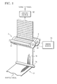
FIG. 1 is a schematic perspective view showing a manufacturing machine according to one embodiment; -
FIG. 2 is a view of a coating device ofFIG 1 as viewed from a rotary screen; -
FIG. 3 is a view of the coating device ofFIG 1 as viewed from a gravure roller; -
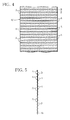
FIG. 4 is a view showing one side of a web passed through the coating device ofFIG 1 ; -
FIG. 5 is a view showing in exaggerated form the profile of the web passed through the coating device ofFIG. 1 ; -
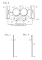
FIG. 6 is a view showing a driving source of a modification example; -
FIG. 7 is a view showing a first modification example of coating patterns; and -
FIG. 8 is a view showing a second modification example of the coating patterns. -
FIG. 1 shows a coating web manufacturing machine and method according to one embodiment. This manufacturing machine manufactures a coated web that is used as wrapping paper for cigarettes with a low ignition propensity - The manufacturing machine shown in
FIG. 1 includes atravel path 2 for web W Thetravel path 2 extends between a supply reel of the web W and a take-up reel of the web W The web W is accordingly reeled off from the supply reel along thetravel path 2. The web W that has been reeled off is taken up by the take-up reel. Thetravel path 2 is formed of a number of guide rollers, among which aguide roller 2a is shown inFIG. 1 . - A coating position is defined in the
travel path 2. Acoating device 3 is placed at the coating position. Thecoating device 3 includes a plate cylinder of a first applicator, namely, arotary screen 4. Therotary screen 4 is rotatably placed on one side of thetravel path 2, and expands in a direction intersecting thetravel path 2, or the web W Thecoating device 3 further includes a plate cylinder of a second applicator, or agravure roller 6. Thegravure roller 6 cooperates with therotary screen 4 to pinch thetravel path 2 between theroller 6 andscreen 4, and is rotatably arranged. Thegravure roller 6 also extends in a direction intersecting thetravel path 2, or the web W Therotary screen 4 and thegravure roller 6 extend parallel with each other, and function as back rollers for each other. - As illustrated in
FIG. 2 , therotary screen 4 is connected to apump 8. Thepump 8 is capable of supplying a liquid burning inhibitor as a first coating liquid into therotary screen 4. During the travel of the web W, when the web W passes the coating position, that is, passes between therotary screen 4 and thegravure roller 6, therotary screen 4 applies the liquid burning inhibitor onto one side of the web W in cooperation with thegravure roller 6 as a back roller and asqueegee 10, thereby forming a number of band layers B in the web W in a predetermined pattern. - In
FIG. 2 , the band layers B are shown with hatching. Referring toFIG 2 , each of the band layers B extends in a direction intersecting the web W across the full width of the web W The band layers B are arranged at predetermined intervals in a travelling direction, or longitudinal direction, of the web W - The liquid burning inhibitor is an aqueous solution containing 2 to 6 percent by mass of alginic sodium, and has a viscosity ranging from 10000 to 200000 mPas. More specifically, the burning inhibitor contains sodium alginates α and β below. The sodium alginates α and β have a compounding ratio ranging from 4:6 to 6:4.
- An aqueous solution containing 1 percent by mass of α, when at a temperature of 20 °C, has a viscosity of 50 mPas or less and a polymerization degree of 300 or less.
- An aqueous solution containing 1 percent by mass of β, when at a temperature of 20 °C, has a viscosity of 800 mPas or more and a polymerization degree of 600 or more.
- As illustrated in
FIGS. 1 and3 , afurnisher roller 12 is in a rolling contact with thegravure roller 6. Thefurnisher roller 12 is rotatably disposed on the opposite side to thetravel path 2, or in such a manner that thegravure roller 6 is sandwiched between thefurnisher roller 12 and the travel path 2.Thegravure roller 6 and thefurnisher roller 12 define an upper nip area in cooperation with each other. An aqueous humor as a second coating liquid, or more specifically water, is supplied to the upper nip area. The upper nip area thus forms a water pool storing the supplied water.FIG 3 shows the water accumulated in the water pool by reference mark L. - A
supply pipe 14 extends from immediately above the water pool. Thesupply pipe 14 is connected to a water source and supplies water to the upper nip area, namely, the water pool. Underneath thefurnisher roller 12, there are disposed a receivingpan 16 and adoctor blade 18. The receivingpan 16 receives water leaking out of the water pool. Thedoctor blade 18 comes into a sliding contact with thegravure roller 6, to thereby remove excess water that has adhered to an outer circumferential surface of thegravure roller 6. Thefurnisher roller 12 includes adrive motor 20 and is rotated by thedrive motor 20. - When the band layers B are formed on one side of the web W as described above, the
gravure roller 6 applies the water supplied from the water pool onto the other side of the web W in cooperation with therotary screen 4 as a back roller, and thus forms a number of wet bands A (dotted area inFIG. 3 ) in the web W at the same time as the formation of the band layers B. The wet bands A also extend across the full width of the web W, and are arranged at predetermined intervals in the travelling direction of the web W As illustrated inFIGS. 4 and 5 , the band layers B and the wet bands A are alternately arranged in the longitudinal direction of the web W For that reason, a number of recesses are formed in the outer circumferential surface of thegravure roller 6 to form the wet bands A. The recesses are arranged at predetermined intervals in a circumferential direction of thegravure roller 6. -
FIGS. 2 and 3 specifically show adrive source 22 for therotary screen 4 and thegravure roller 6. Thedrive source 22 includes adrive motor 24 common to therotary screen 4 and thegravure roller 6. Thedrive motor 24 is connected to therotary screen 4 and thegravure roller 6 via agear train 26. Thegear train 26 has anoutput gear 28 mounted on an output shaft of thedrive motor 24, and drive gears 30 and 32 directly or indirectly engaged with theoutput gear 28. Thedrive gear 30 is mounted on a rotary shaft of therotary screen 4, and thedrive gear 32 is mounted on a roller shaft of thegravure roller 6. - According to the
drive source 22, when thedrive motor 24 is driven, therotary screen 4 and thegravure roller 6 rotate in sync with each other, and properly form the band layers B and the wet bands A in the web W - The
travel path 2 has a dryingdevice 52, which is placed downstream of therotary screen 4 and thegravure roller 6. When the web W passes through the dryingdevice 52, the dryingdevice 52 heats both the sides of the web W, namely, the band layers B and the wet bands A, for example, up to 120 °C to 130 °C. The band layers B and the wet bands A are then quickly dried. After this drying process, the web W is taken up by the take-up reel as a wrapping paper web. - Before being subjected to the drying process, the web W is substantially evenly wet because of the band layers B and the wet bands A. Even if the web W shrinks due to the drying process, therefore, the shrinkage evenly takes place all over the web W This considerably reduces wrinkles appearing in the web after the drying process.
- Since the band layers B and the wet bands A are formed in the different sides of the web W, the water contained in the wet bands A is not mixed with the liquid burning inhibitor forming the band layers B. Consequently, the formation of the wet bands A, or the application of water onto the web W, does not adversely affect the formation of the band layers B. The band layers B therefore can be properly formed.
- When the wrapping paper web has the same width as cigarette wrapping paper, the wrapping paper web taken up by the take-up reel is directly fitted as a web roll to a cigarette manufacturing machine and used to manufacture cigarettes with a low ignition propensity When the wrapping paper web is greater in width than the cigarette wrapping paper, the wrapping paper web taken up by the take-up reel is subjected to a cutting process to turn into web rolls.
- The invention is not restricted by the first embodiment and may be modified in various ways.
- For example,
FIG 6 shows adrive source 23 according to a modification example. Thedrive source 23 includes twoservomotors servomotors rotary screen 4 and thegravure roller 6, respectively, thereby rotating therotary screen 4 and thegravure roller 6 independently. - The
servomotor 34 has an output shaft and anoutput gear 38 mounted on this output shaft. Theoutput gear 38 is engaged with thedrive gear 30 of therotary screen 4. Theservomotor 36 has an output shaft and anoutput gear 40 mounted on this output shaft. Theoutput gear 40 is engaged with thedrive gear 32 of thegravure roller 6. - When the
rotary screen 4 and thegravure roller 6 are independently rotated as mentioned above, it is required to synchronize the rotations of therotary screen 4 and thegravure roller 6 in order to properly form the band layers B and the web bands A. To that end, thedrive source 23 further has asynchronization mechanism 43. - The
synchronization mechanism 43 includes to-be-detected elements rotary screen 4 and thegravure roller 6;synchronization sensors be-detected elements controller 50 for receiving detection signals from thesynchronization sensors servomotors - The
controller 50 determines difference between the rotations of therotary screen 4 and thegravure roller 6 on the basis of the detection signal from thesynchronization sensor 48, using the detection signal from thesynchronization sensor 46 as a criterion. Based upon a result of the determination, thecontroller 50 controls the rotation of theservomotor 36, and thus synchronizes the rotations of therotary screen 4 and thegravure roller 6. This enables therotary screen 4 and thegravure roller 6 to properly form the band layers B and the wet bands A on the respective sides of the web W - The
synchronization mechanism 43 may use absolute rotary encoders (not shown), instead of thesynchronization sensor 46, which are built in theservomotors controller 50 angle signals indicative of rotation angles of therotary screen 4 and thegravure roller 6. Based upon the angle signals from the rotary encoders, thecontroller 50 synchronizes the rotations of therotary screen 4 and thegravure roller 6. - The manufacturing machine of the invention may be interposed in a supply path of web used as wrapping paper for cigarettes with a low ignition propensity, in the above-mentioned cigarette manufacturing apparatus. Furthermore, the burning inhibitor and the aqueous humor are also not limited to those mentioned in the one embodiment.
- The invention is applicable to manufacture of not only the wrapping paper web for cigarettes with a low ignition propensity but also various kinds of coating webs.
- The manufacturing machine and method according to the invention, as illustrated in
FIG. 7 , apply the first coating liquid onto one side of the web W to form a coating layer X on the entire one side of the web W, and apply the second coating liquid onto the other side of the web W to form a number of band layers Y on the other side of the web W In this case, the band layers Y are arranged at predetermined intervals in the longitudinal direction of the web W - As illustrated in
FIG. 8 , the manufacturing machine and method according to the invention are capable of forming a number of band layers Za and Zb on the respective sides of the web W In this case, the band layers Za and Zb are arranged at predetermined intervals in the longitudinal direction of the web W The band layers Za are arranged on the opposite side of the web W to their respective band layers Zb so that the web W is sandwiched therebetween. - The manufacturing machine of the invention is not limited in combination of the rotary screen and the gravure roller. It is possible to use a combination of a plate cylinder for flexographic or offset printing and a rotary screen, or a combination of a plate cylinder for gravure, flexographic or offset printing and a plate cylinder for flexographic printing.
- Furthermore, various kinds of coating liquids may be utilized as the first and second coating liquids.
-
- 2
- travel path
- 3
- coating device
- 4
- rotary screen (first applicator)
- 6
- gravure roller (second applicator)
- 12
- furnisher roller
- 22, 23
- drive source
- 24
- drive motor
- 26
- gear train
- 43
- synchronization mechanism
- 52
- drying device
- A
- wet band
- B
- band layer (burning inhibitor)
- L
- water (aqueous humor)
- W
- web
Claims (9)
- A coated web manufacturing machine comprising:a travel path adapted for traveling web, said travel path including a coating position defined in said travel path, anda coating device located at the coating position of said travel path, wherein:said coating device includes:a first applicator for applying a first coating liquid onto one side of web, anda second applicator for applying a second coating liquid onto the other side of the web.
- The coated web manufacturing machine according to claim 1, further comprising a drying device interposed in said travel path to be located downstream of said coating device, for drying the web.
- The coated web manufacturing machine according to claim 2, wherein the first and second applicator are both of a wheel type, and have plate cylinders for applying the first and second coating liquids onto the web.
- The coated web manufacturing machine according to claim 3, wherein either one of the first and second applicators has a rotary screen serving as a plate cylinder, and
the other applicator also functions as a back roller for the rotary screen, and the rotary screen functions as a back roller for the plate cylinder of the other applicator. - The coated web manufacturing machine according to claim 4, wherein said coating device further includes:a drive motor common to the plate cylinders of the first and second applicators, anda gear train for transmitting a driving force from the drive motor to the plate cylinders of the first and second applicators.
- The coated web manufacturing machine according to claim 4, wherein said coating device further includes:a drive motor provided to each of the plate cylinders of the first and second applicators, anda synchronization mechanism for synchronizing rotations of the plate cylinders of the first and second applicators.
- The coated web manufacturing apparatus according to claim 4, wherein:the web is used for manufacturing cigarettes;the first applicator intermittently applies a liquid burning inhibitor functioning as the first coating liquid onto one side of the web, and thus forms a number of band layers arranged at predetermined intervals in a travelling direction of the web and made of burning inhibitor; andthe second applicator applies aqueous humor functioning as the second coating liquid onto areas on the other side of the web, which coincide with intervals between the band layers of the one side of the web.
- The coated web manufacturing apparatus according to claim 7, wherein:the liquid burning inhibitor is an aqueous solution of sodium alginate, andthe aqueous humor is water.
- A coated web manufacturing method comprising the steps of:travelling web along a travel path, andapplying a first coating liquid onto one side of the web and second coating liquid onto the other side of the web at the same time when the web passes through a coating position defined in the travel path.
Applications Claiming Priority (2)
| Application Number | Priority Date | Filing Date | Title |
|---|---|---|---|
| JP2008275387A JP5250383B2 (en) | 2008-10-27 | 2008-10-27 | Coating web manufacturing apparatus and manufacturing method thereof |
| PCT/JP2009/068255 WO2010050411A1 (en) | 2008-10-27 | 2009-10-23 | Coated web manufacturing machine and manufacturing method |
Publications (3)
| Publication Number | Publication Date |
|---|---|
| EP2351618A1 true EP2351618A1 (en) | 2011-08-03 |
| EP2351618A4 EP2351618A4 (en) | 2012-07-25 |
| EP2351618B1 EP2351618B1 (en) | 2016-01-13 |
Family
ID=42128774
Family Applications (1)
| Application Number | Title | Priority Date | Filing Date |
|---|---|---|---|
| EP09823522.9A Not-in-force EP2351618B1 (en) | 2008-10-27 | 2009-10-23 | Coated web manufacturing machine and manufacturing method |
Country Status (5)
| Country | Link |
|---|---|
| US (1) | US9346073B2 (en) |
| EP (1) | EP2351618B1 (en) |
| JP (1) | JP5250383B2 (en) |
| ES (1) | ES2565084T3 (en) |
| WO (1) | WO2010050411A1 (en) |
Cited By (2)
| Publication number | Priority date | Publication date | Assignee | Title |
|---|---|---|---|---|
| CN111629838A (en) * | 2018-03-22 | 2020-09-04 | 富士胶片株式会社 | Coating device and coating system |
| EP4124390A1 (en) * | 2021-07-26 | 2023-02-01 | Collin Lab & Pilot Solutions GmbH | Coating device and coating method |
Families Citing this family (13)
| Publication number | Priority date | Publication date | Assignee | Title |
|---|---|---|---|---|
| TWI446974B (en) * | 2009-06-30 | 2014-08-01 | 東麗工程股份有限公司 | And a conveyor device for coating the substrate on both sides |
| WO2012131866A1 (en) * | 2011-03-28 | 2012-10-04 | 日本たばこ産業株式会社 | Cigarette rolling paper manufacturing method and manufacturing device |
| CN102493280A (en) | 2011-12-02 | 2012-06-13 | 牡丹江恒丰纸业股份有限公司 | Device and method for manufacturing cigarette paper with flame-retardant belt |
| US9555439B2 (en) | 2013-08-12 | 2017-01-31 | Building Materials Investment Corporation | High speed granule delivery system and method |
| MX343524B (en) | 2012-08-13 | 2016-11-09 | Building Materials Invest Corp | High speed granule delivery system and method. |
| US9359765B2 (en) * | 2012-08-13 | 2016-06-07 | Building Materials Investment Corporation | High speed granule delivery system and method |
| JP5784071B2 (en) * | 2013-04-26 | 2015-09-24 | 株式会社理峰 | Pattern coating apparatus and coating method |
| US9498795B2 (en) | 2013-09-11 | 2016-11-22 | Building Materials Investment Corporation | Method and apparatus for sharp color definition on the application of granules to roofing substrates |
| CN110582409A (en) * | 2017-01-17 | 2019-12-17 | 塞奇机动车内饰股份有限公司 | Rotary Screen Pattern Printing of Polyurethane Resin on Textiles |
| KR101963767B1 (en) * | 2017-02-22 | 2019-03-29 | 주식회사 아이센스 | Coating device for wire electrode manufacturing |
| CN113953137A (en) * | 2021-11-04 | 2022-01-21 | 四川美宁食品有限公司 | Longitudinal and transverse gap coating device and method for tinplate for can packaging |
| KR102765974B1 (en) * | 2022-12-30 | 2025-02-11 | 주식회사 엠에스 오토텍 | Sealer Dispensing Apparatus |
| US20250239586A1 (en) * | 2024-01-18 | 2025-07-24 | Durr Systems, Inc. | Apparatus And Method For Inductive Heating Of Coated Web Substrates During Process Operations |
Family Cites Families (21)
| Publication number | Priority date | Publication date | Assignee | Title |
|---|---|---|---|---|
| NL276182A (en) * | 1961-04-05 | 1900-01-01 | ||
| US3552353A (en) * | 1966-12-05 | 1971-01-05 | Raymond A Labombarde | Apparatus for applying high viscosity coatings |
| US3540410A (en) * | 1968-08-20 | 1970-11-17 | Du Pont | Coating machine having spiral surface agitator roll |
| SE378769B (en) * | 1972-03-13 | 1975-09-15 | Inventing Ab | |
| JPH0214004A (en) * | 1988-06-29 | 1990-01-18 | Kanai Hiroyuki | Production of water-repellent bondable padding cloth |
| US5015317A (en) * | 1988-12-22 | 1991-05-14 | Comfortex Corporation | Method and apparatus for making a multi-cellular collapsible shade |
| US5393566A (en) * | 1992-10-27 | 1995-02-28 | Tim-Bar Coproration | Recyclable plastic coated containers |
| US5476567A (en) * | 1993-03-26 | 1995-12-19 | Yamaha Gamagori Seizo Kabushiki | Method and apparatus for fabricating resin mats |
| JPH06286106A (en) * | 1993-04-05 | 1994-10-11 | Matsushita Electric Ind Co Ltd | Pattern printing method and pattern printing machine used therefor |
| DE19629605C2 (en) * | 1996-07-23 | 2000-02-03 | Koenig & Bauer Ag | Drive a printing unit |
| US5985028A (en) * | 1997-09-12 | 1999-11-16 | Henkel Corporation | Coating apparatus |
| JPH11321063A (en) * | 1998-03-20 | 1999-11-24 | Tohoku Ricoh Co Ltd | Stencil printing machine |
| EP1057541A1 (en) * | 1999-06-04 | 2000-12-06 | Solipat Ag | Device and method for partially applying a coating and web with a partial coating |
| EP2127543B1 (en) * | 2000-11-13 | 2012-09-12 | Schweitzer-Mauduit International | Process for producing paper wrappers and smoking articles with reduced ignition proclivity characteristics |
| US6645605B2 (en) * | 2001-01-15 | 2003-11-11 | James Rodney Hammersmith | Materials and method of making same for low ignition propensity products |
| JP2003136669A (en) * | 2001-11-02 | 2003-05-14 | Mitsubishi Heavy Ind Ltd | Cylinder drive for offset double-sided printing press |
| US7563326B2 (en) * | 2002-06-24 | 2009-07-21 | Voith Paper Patent Gmbh | Device for coating and drying both sides of a material web of paper or board |
| KR20070111481A (en) * | 2005-02-16 | 2007-11-21 | 쓰리엠 이노베이티브 프로퍼티즈 컴파니 | Methods of Making Topographically Patterned Coatings |
| JP2008155073A (en) * | 2006-12-20 | 2008-07-10 | Nihon Micro Coating Co Ltd | Coating apparatus |
| KR101238596B1 (en) | 2007-07-16 | 2013-03-04 | 덴탈포인트 아게 | Dental implant |
| BRPI0907699A2 (en) | 2008-02-08 | 2015-07-21 | Japan Tobacco Inc | Production Method to Produce a Cigarette Wrap |
-
2008
- 2008-10-27 JP JP2008275387A patent/JP5250383B2/en not_active Expired - Fee Related
-
2009
- 2009-10-23 WO PCT/JP2009/068255 patent/WO2010050411A1/en not_active Ceased
- 2009-10-23 EP EP09823522.9A patent/EP2351618B1/en not_active Not-in-force
- 2009-10-23 ES ES09823522.9T patent/ES2565084T3/en active Active
-
2011
- 2011-04-26 US US13/094,252 patent/US9346073B2/en not_active Expired - Fee Related
Cited By (4)
| Publication number | Priority date | Publication date | Assignee | Title |
|---|---|---|---|---|
| CN111629838A (en) * | 2018-03-22 | 2020-09-04 | 富士胶片株式会社 | Coating device and coating system |
| EP4124390A1 (en) * | 2021-07-26 | 2023-02-01 | Collin Lab & Pilot Solutions GmbH | Coating device and coating method |
| WO2023006407A1 (en) * | 2021-07-26 | 2023-02-02 | Collin Lab & Pilot Solutions Gmbh | Coating device and coating method |
| US12415201B2 (en) | 2021-07-26 | 2025-09-16 | Collin Lab & Pilot Solutions Gmbh | Coating device and coating method |
Also Published As
| Publication number | Publication date |
|---|---|
| EP2351618B1 (en) | 2016-01-13 |
| US20110200747A1 (en) | 2011-08-18 |
| JP5250383B2 (en) | 2013-07-31 |
| WO2010050411A1 (en) | 2010-05-06 |
| US9346073B2 (en) | 2016-05-24 |
| ES2565084T3 (en) | 2016-03-31 |
| EP2351618A4 (en) | 2012-07-25 |
| JP2010099630A (en) | 2010-05-06 |
Similar Documents
| Publication | Publication Date | Title |
|---|---|---|
| US9346073B2 (en) | Coated web manufacturing machine | |
| US5735292A (en) | Method and device for the production of filter tip bands for ventilated cigarettes | |
| CN103025512B (en) | Method for embossing a tip cover of a cigarette tip | |
| CN101232824A (en) | Cigarette paper with gravure printed band | |
| CN102046382A (en) | Device for cold foil embossing | |
| FI64411C (en) | PROCEDURE FOR THE PURPOSE OF OPERATION OF THE PAPER | |
| US20140251169A1 (en) | Method for adjusting the distances between cylinders of an inking unit and printing machine | |
| CN1997517A (en) | Printing machine with embossing device | |
| EP2832535B1 (en) | Embossing device | |
| EP2436518B1 (en) | Variable cutoff printing press and method for double printing | |
| US20110244132A1 (en) | Method for producing a pattern on an endless strip | |
| EP3132860B1 (en) | Glue distribution device and embossing-lamination assembly provided therewith | |
| KR20100005031A (en) | Method and device for trapping ink | |
| JP2015066520A (en) | Coating equipment and coating method | |
| CA2282122A1 (en) | Method and apparatus for applying stripes to a moving web | |
| US20200122454A1 (en) | Device for coating panels, printing press, and method for coating panels | |
| RU2258008C2 (en) | System for dosage for paint rolling on shafts in printing press | |
| JP2007533482A (en) | Intaglio printing device | |
| GB1338794A (en) | Method and apparatus for applying adhesive seams to webs | |
| CN110072789B (en) | Machine and method for sealing the trailing end of a roll of web material | |
| KR850001029A (en) | Coating device | |
| DK2571694T3 (en) | Format Related cold-stamping | |
| GB2429430A (en) | Offset rotary screen printer | |
| EA050918B1 (en) | TENSION ROLL OF A FLEXOGRAPHIC PRINTING MACHINE AND A METHOD OF FLEXOGRAPHIC PRINTING WITH ITS USE IN THE PRODUCTION OF LAMINATED PLYWOOD | |
| GB2184064A (en) | Printing on continuous webs |
Legal Events
| Date | Code | Title | Description |
|---|---|---|---|
| PUAI | Public reference made under article 153(3) epc to a published international application that has entered the european phase |
Free format text: ORIGINAL CODE: 0009012 |
|
| 17P | Request for examination filed |
Effective date: 20110524 |
|
| AK | Designated contracting states |
Kind code of ref document: A1 Designated state(s): AT BE BG CH CY CZ DE DK EE ES FI FR GB GR HR HU IE IS IT LI LT LU LV MC MK MT NL NO PL PT RO SE SI SK SM TR |
|
| DAX | Request for extension of the european patent (deleted) | ||
| A4 | Supplementary search report drawn up and despatched |
Effective date: 20120622 |
|
| RIC1 | Information provided on ipc code assigned before grant |
Ipc: A24D 1/02 20060101ALI20120618BHEP Ipc: B05C 9/04 20060101AFI20120618BHEP Ipc: B05C 1/16 20060101ALI20120618BHEP Ipc: B05C 1/08 20060101ALI20120618BHEP |
|
| 17Q | First examination report despatched |
Effective date: 20141021 |
|
| REG | Reference to a national code |
Ref country code: DE Ref legal event code: R079 Ref document number: 602009035895 Country of ref document: DE Free format text: PREVIOUS MAIN CLASS: B05C0009040000 Ipc: A24C0005000000 |
|
| RIC1 | Information provided on ipc code assigned before grant |
Ipc: D21H 19/68 20060101ALN20150722BHEP Ipc: B05C 1/10 20060101ALN20150722BHEP Ipc: B05C 1/08 20060101ALI20150722BHEP Ipc: D21H 23/56 20060101ALI20150722BHEP Ipc: B05C 9/04 20060101ALN20150722BHEP Ipc: A24C 5/00 20060101AFI20150722BHEP Ipc: B05C 1/16 20060101ALI20150722BHEP Ipc: A24D 1/02 20060101ALI20150722BHEP |
|
| GRAP | Despatch of communication of intention to grant a patent |
Free format text: ORIGINAL CODE: EPIDOSNIGR1 |
|
| RIC1 | Information provided on ipc code assigned before grant |
Ipc: A24C 5/00 20060101AFI20150807BHEP Ipc: A24D 1/02 20060101ALI20150807BHEP Ipc: B05C 1/08 20060101ALI20150807BHEP Ipc: B05C 1/10 20060101ALN20150807BHEP Ipc: B05C 1/16 20060101ALI20150807BHEP Ipc: B05C 9/04 20060101ALN20150807BHEP Ipc: D21H 19/68 20060101ALN20150807BHEP Ipc: D21H 23/56 20060101ALI20150807BHEP |
|
| INTG | Intention to grant announced |
Effective date: 20150903 |
|
| GRAS | Grant fee paid |
Free format text: ORIGINAL CODE: EPIDOSNIGR3 |
|
| GRAA | (expected) grant |
Free format text: ORIGINAL CODE: 0009210 |
|
| AK | Designated contracting states |
Kind code of ref document: B1 Designated state(s): AT BE BG CH CY CZ DE DK EE ES FI FR GB GR HR HU IE IS IT LI LT LU LV MC MK MT NL NO PL PT RO SE SI SK SM TR |
|
| REG | Reference to a national code |
Ref country code: GB Ref legal event code: FG4D |
|
| REG | Reference to a national code |
Ref country code: CH Ref legal event code: EP |
|
| REG | Reference to a national code |
Ref country code: IE Ref legal event code: FG4D |
|
| REG | Reference to a national code |
Ref country code: AT Ref legal event code: REF Ref document number: 769888 Country of ref document: AT Kind code of ref document: T Effective date: 20160215 |
|
| REG | Reference to a national code |
Ref country code: DE Ref legal event code: R096 Ref document number: 602009035895 Country of ref document: DE |
|
| REG | Reference to a national code |
Ref country code: ES Ref legal event code: FG2A Ref document number: 2565084 Country of ref document: ES Kind code of ref document: T3 Effective date: 20160331 |
|
| REG | Reference to a national code |
Ref country code: LT Ref legal event code: MG4D |
|
| REG | Reference to a national code |
Ref country code: NL Ref legal event code: MP Effective date: 20160113 |
|
| PG25 | Lapsed in a contracting state [announced via postgrant information from national office to epo] |
Ref country code: NL Free format text: LAPSE BECAUSE OF FAILURE TO SUBMIT A TRANSLATION OF THE DESCRIPTION OR TO PAY THE FEE WITHIN THE PRESCRIBED TIME-LIMIT Effective date: 20160113 |
|
| PG25 | Lapsed in a contracting state [announced via postgrant information from national office to epo] |
Ref country code: IT Free format text: LAPSE BECAUSE OF FAILURE TO SUBMIT A TRANSLATION OF THE DESCRIPTION OR TO PAY THE FEE WITHIN THE PRESCRIBED TIME-LIMIT Effective date: 20160113 Ref country code: NO Free format text: LAPSE BECAUSE OF FAILURE TO SUBMIT A TRANSLATION OF THE DESCRIPTION OR TO PAY THE FEE WITHIN THE PRESCRIBED TIME-LIMIT Effective date: 20160413 Ref country code: FI Free format text: LAPSE BECAUSE OF FAILURE TO SUBMIT A TRANSLATION OF THE DESCRIPTION OR TO PAY THE FEE WITHIN THE PRESCRIBED TIME-LIMIT Effective date: 20160113 Ref country code: HR Free format text: LAPSE BECAUSE OF FAILURE TO SUBMIT A TRANSLATION OF THE DESCRIPTION OR TO PAY THE FEE WITHIN THE PRESCRIBED TIME-LIMIT Effective date: 20160113 Ref country code: GR Free format text: LAPSE BECAUSE OF FAILURE TO SUBMIT A TRANSLATION OF THE DESCRIPTION OR TO PAY THE FEE WITHIN THE PRESCRIBED TIME-LIMIT Effective date: 20160414 |
|
| PG25 | Lapsed in a contracting state [announced via postgrant information from national office to epo] |
Ref country code: IS Free format text: LAPSE BECAUSE OF FAILURE TO SUBMIT A TRANSLATION OF THE DESCRIPTION OR TO PAY THE FEE WITHIN THE PRESCRIBED TIME-LIMIT Effective date: 20160513 Ref country code: PT Free format text: LAPSE BECAUSE OF FAILURE TO SUBMIT A TRANSLATION OF THE DESCRIPTION OR TO PAY THE FEE WITHIN THE PRESCRIBED TIME-LIMIT Effective date: 20160513 Ref country code: LV Free format text: LAPSE BECAUSE OF FAILURE TO SUBMIT A TRANSLATION OF THE DESCRIPTION OR TO PAY THE FEE WITHIN THE PRESCRIBED TIME-LIMIT Effective date: 20160113 Ref country code: SE Free format text: LAPSE BECAUSE OF FAILURE TO SUBMIT A TRANSLATION OF THE DESCRIPTION OR TO PAY THE FEE WITHIN THE PRESCRIBED TIME-LIMIT Effective date: 20160113 Ref country code: PL Free format text: LAPSE BECAUSE OF FAILURE TO SUBMIT A TRANSLATION OF THE DESCRIPTION OR TO PAY THE FEE WITHIN THE PRESCRIBED TIME-LIMIT Effective date: 20160113 Ref country code: LT Free format text: LAPSE BECAUSE OF FAILURE TO SUBMIT A TRANSLATION OF THE DESCRIPTION OR TO PAY THE FEE WITHIN THE PRESCRIBED TIME-LIMIT Effective date: 20160113 |
|
| REG | Reference to a national code |
Ref country code: DE Ref legal event code: R097 Ref document number: 602009035895 Country of ref document: DE |
|
| PG25 | Lapsed in a contracting state [announced via postgrant information from national office to epo] |
Ref country code: EE Free format text: LAPSE BECAUSE OF FAILURE TO SUBMIT A TRANSLATION OF THE DESCRIPTION OR TO PAY THE FEE WITHIN THE PRESCRIBED TIME-LIMIT Effective date: 20160113 Ref country code: DK Free format text: LAPSE BECAUSE OF FAILURE TO SUBMIT A TRANSLATION OF THE DESCRIPTION OR TO PAY THE FEE WITHIN THE PRESCRIBED TIME-LIMIT Effective date: 20160113 |
|
| PLBE | No opposition filed within time limit |
Free format text: ORIGINAL CODE: 0009261 |
|
| STAA | Information on the status of an ep patent application or granted ep patent |
Free format text: STATUS: NO OPPOSITION FILED WITHIN TIME LIMIT |
|
| PG25 | Lapsed in a contracting state [announced via postgrant information from national office to epo] |
Ref country code: CZ Free format text: LAPSE BECAUSE OF FAILURE TO SUBMIT A TRANSLATION OF THE DESCRIPTION OR TO PAY THE FEE WITHIN THE PRESCRIBED TIME-LIMIT Effective date: 20160113 Ref country code: RO Free format text: LAPSE BECAUSE OF FAILURE TO SUBMIT A TRANSLATION OF THE DESCRIPTION OR TO PAY THE FEE WITHIN THE PRESCRIBED TIME-LIMIT Effective date: 20160113 Ref country code: SK Free format text: LAPSE BECAUSE OF FAILURE TO SUBMIT A TRANSLATION OF THE DESCRIPTION OR TO PAY THE FEE WITHIN THE PRESCRIBED TIME-LIMIT Effective date: 20160113 Ref country code: SM Free format text: LAPSE BECAUSE OF FAILURE TO SUBMIT A TRANSLATION OF THE DESCRIPTION OR TO PAY THE FEE WITHIN THE PRESCRIBED TIME-LIMIT Effective date: 20160113 |
|
| 26N | No opposition filed |
Effective date: 20161014 |
|
| PG25 | Lapsed in a contracting state [announced via postgrant information from national office to epo] |
Ref country code: BE Free format text: LAPSE BECAUSE OF FAILURE TO SUBMIT A TRANSLATION OF THE DESCRIPTION OR TO PAY THE FEE WITHIN THE PRESCRIBED TIME-LIMIT Effective date: 20160113 |
|
| PG25 | Lapsed in a contracting state [announced via postgrant information from national office to epo] |
Ref country code: SI Free format text: LAPSE BECAUSE OF FAILURE TO SUBMIT A TRANSLATION OF THE DESCRIPTION OR TO PAY THE FEE WITHIN THE PRESCRIBED TIME-LIMIT Effective date: 20160113 Ref country code: BG Free format text: LAPSE BECAUSE OF FAILURE TO SUBMIT A TRANSLATION OF THE DESCRIPTION OR TO PAY THE FEE WITHIN THE PRESCRIBED TIME-LIMIT Effective date: 20160413 |
|
| REG | Reference to a national code |
Ref country code: CH Ref legal event code: PL |
|
| GBPC | Gb: european patent ceased through non-payment of renewal fee |
Effective date: 20161023 |
|
| REG | Reference to a national code |
Ref country code: IE Ref legal event code: MM4A |
|
| REG | Reference to a national code |
Ref country code: FR Ref legal event code: ST Effective date: 20170630 |
|
| PG25 | Lapsed in a contracting state [announced via postgrant information from national office to epo] |
Ref country code: GB Free format text: LAPSE BECAUSE OF NON-PAYMENT OF DUE FEES Effective date: 20161023 Ref country code: LI Free format text: LAPSE BECAUSE OF NON-PAYMENT OF DUE FEES Effective date: 20161031 Ref country code: FR Free format text: LAPSE BECAUSE OF NON-PAYMENT OF DUE FEES Effective date: 20161102 Ref country code: CH Free format text: LAPSE BECAUSE OF NON-PAYMENT OF DUE FEES Effective date: 20161031 |
|
| PG25 | Lapsed in a contracting state [announced via postgrant information from national office to epo] |
Ref country code: LU Free format text: LAPSE BECAUSE OF NON-PAYMENT OF DUE FEES Effective date: 20161023 |
|
| REG | Reference to a national code |
Ref country code: AT Ref legal event code: UEP Ref document number: 769888 Country of ref document: AT Kind code of ref document: T Effective date: 20160113 |
|
| PG25 | Lapsed in a contracting state [announced via postgrant information from national office to epo] |
Ref country code: IE Free format text: LAPSE BECAUSE OF NON-PAYMENT OF DUE FEES Effective date: 20161023 |
|
| PG25 | Lapsed in a contracting state [announced via postgrant information from national office to epo] |
Ref country code: CY Free format text: LAPSE BECAUSE OF FAILURE TO SUBMIT A TRANSLATION OF THE DESCRIPTION OR TO PAY THE FEE WITHIN THE PRESCRIBED TIME-LIMIT Effective date: 20160113 Ref country code: HU Free format text: LAPSE BECAUSE OF FAILURE TO SUBMIT A TRANSLATION OF THE DESCRIPTION OR TO PAY THE FEE WITHIN THE PRESCRIBED TIME-LIMIT; INVALID AB INITIO Effective date: 20091023 |
|
| PG25 | Lapsed in a contracting state [announced via postgrant information from national office to epo] |
Ref country code: MK Free format text: LAPSE BECAUSE OF FAILURE TO SUBMIT A TRANSLATION OF THE DESCRIPTION OR TO PAY THE FEE WITHIN THE PRESCRIBED TIME-LIMIT Effective date: 20160113 Ref country code: MC Free format text: LAPSE BECAUSE OF FAILURE TO SUBMIT A TRANSLATION OF THE DESCRIPTION OR TO PAY THE FEE WITHIN THE PRESCRIBED TIME-LIMIT Effective date: 20160113 Ref country code: MT Free format text: LAPSE BECAUSE OF NON-PAYMENT OF DUE FEES Effective date: 20161031 Ref country code: TR Free format text: LAPSE BECAUSE OF FAILURE TO SUBMIT A TRANSLATION OF THE DESCRIPTION OR TO PAY THE FEE WITHIN THE PRESCRIBED TIME-LIMIT Effective date: 20160113 |
|
| PGFP | Annual fee paid to national office [announced via postgrant information from national office to epo] |
Ref country code: ES Payment date: 20211223 Year of fee payment: 13 Ref country code: AT Payment date: 20211021 Year of fee payment: 13 Ref country code: DE Payment date: 20211020 Year of fee payment: 13 |
|
| REG | Reference to a national code |
Ref country code: DE Ref legal event code: R119 Ref document number: 602009035895 Country of ref document: DE |
|
| REG | Reference to a national code |
Ref country code: AT Ref legal event code: MM01 Ref document number: 769888 Country of ref document: AT Kind code of ref document: T Effective date: 20221023 |
|
| PG25 | Lapsed in a contracting state [announced via postgrant information from national office to epo] |
Ref country code: DE Free format text: LAPSE BECAUSE OF NON-PAYMENT OF DUE FEES Effective date: 20230503 Ref country code: AT Free format text: LAPSE BECAUSE OF NON-PAYMENT OF DUE FEES Effective date: 20221023 |
|
| REG | Reference to a national code |
Ref country code: ES Ref legal event code: FD2A Effective date: 20231130 |
|
| PG25 | Lapsed in a contracting state [announced via postgrant information from national office to epo] |
Ref country code: ES Free format text: LAPSE BECAUSE OF NON-PAYMENT OF DUE FEES Effective date: 20221024 |
|
| PG25 | Lapsed in a contracting state [announced via postgrant information from national office to epo] |
Ref country code: ES Free format text: LAPSE BECAUSE OF NON-PAYMENT OF DUE FEES Effective date: 20221024 |