EP2351550A1 - Connector - Google Patents
Connector Download PDFInfo
- Publication number
- EP2351550A1 EP2351550A1 EP20090828991 EP09828991A EP2351550A1 EP 2351550 A1 EP2351550 A1 EP 2351550A1 EP 20090828991 EP20090828991 EP 20090828991 EP 09828991 A EP09828991 A EP 09828991A EP 2351550 A1 EP2351550 A1 EP 2351550A1
- Authority
- EP
- European Patent Office
- Prior art keywords
- hole
- stopcock
- flow channel
- tubular portion
- drug solution
- Prior art date
- Legal status (The legal status is an assumption and is not a legal conclusion. Google has not performed a legal analysis and makes no representation as to the accuracy of the status listed.)
- Withdrawn
Links
- 238000004891 communication Methods 0.000 claims abstract description 51
- 239000007788 liquid Substances 0.000 claims description 34
- 238000012546 transfer Methods 0.000 claims description 31
- 230000002209 hydrophobic effect Effects 0.000 claims description 10
- 230000000149 penetrating effect Effects 0.000 claims description 6
- 239000003814 drug Substances 0.000 description 198
- 229940079593 drug Drugs 0.000 description 198
- 239000000243 solution Substances 0.000 description 176
- 239000002904 solvent Substances 0.000 description 49
- 238000010586 diagram Methods 0.000 description 8
- 210000000078 claw Anatomy 0.000 description 7
- 239000000843 powder Substances 0.000 description 6
- 239000011521 glass Substances 0.000 description 5
- 238000002347 injection Methods 0.000 description 4
- 239000007924 injection Substances 0.000 description 4
- 239000003085 diluting agent Substances 0.000 description 3
- 230000002093 peripheral effect Effects 0.000 description 3
- 239000002246 antineoplastic agent Substances 0.000 description 2
- 238000004090 dissolution Methods 0.000 description 2
- 238000003780 insertion Methods 0.000 description 2
- 230000037431 insertion Effects 0.000 description 2
- 238000000034 method Methods 0.000 description 2
- 238000011017 operating method Methods 0.000 description 2
- 238000005192 partition Methods 0.000 description 2
- 230000035699 permeability Effects 0.000 description 2
- 239000011347 resin Substances 0.000 description 2
- 229920005989 resin Polymers 0.000 description 2
- 239000000853 adhesive Substances 0.000 description 1
- 230000001070 adhesive effect Effects 0.000 description 1
- 238000005452 bending Methods 0.000 description 1
- 230000000694 effects Effects 0.000 description 1
- 239000012530 fluid Substances 0.000 description 1
- 238000005304 joining Methods 0.000 description 1
- 239000002184 metal Substances 0.000 description 1
- 239000000825 pharmaceutical preparation Substances 0.000 description 1
- 238000012545 processing Methods 0.000 description 1
- 238000007493 shaping process Methods 0.000 description 1
- 239000007779 soft material Substances 0.000 description 1
- 238000003860 storage Methods 0.000 description 1
- 231100000331 toxic Toxicity 0.000 description 1
- 230000002588 toxic effect Effects 0.000 description 1
- 238000003466 welding Methods 0.000 description 1
Images











Classifications
-
- A—HUMAN NECESSITIES
- A61—MEDICAL OR VETERINARY SCIENCE; HYGIENE
- A61J—CONTAINERS SPECIALLY ADAPTED FOR MEDICAL OR PHARMACEUTICAL PURPOSES; DEVICES OR METHODS SPECIALLY ADAPTED FOR BRINGING PHARMACEUTICAL PRODUCTS INTO PARTICULAR PHYSICAL OR ADMINISTERING FORMS; DEVICES FOR ADMINISTERING FOOD OR MEDICINES ORALLY; BABY COMFORTERS; DEVICES FOR RECEIVING SPITTLE
- A61J1/00—Containers specially adapted for medical or pharmaceutical purposes
- A61J1/14—Details; Accessories therefor
- A61J1/20—Arrangements for transferring or mixing fluids, e.g. from vial to syringe
- A61J1/2089—Containers or vials which are to be joined to each other in order to mix their contents
-
- A—HUMAN NECESSITIES
- A61—MEDICAL OR VETERINARY SCIENCE; HYGIENE
- A61J—CONTAINERS SPECIALLY ADAPTED FOR MEDICAL OR PHARMACEUTICAL PURPOSES; DEVICES OR METHODS SPECIALLY ADAPTED FOR BRINGING PHARMACEUTICAL PRODUCTS INTO PARTICULAR PHYSICAL OR ADMINISTERING FORMS; DEVICES FOR ADMINISTERING FOOD OR MEDICINES ORALLY; BABY COMFORTERS; DEVICES FOR RECEIVING SPITTLE
- A61J1/00—Containers specially adapted for medical or pharmaceutical purposes
- A61J1/14—Details; Accessories therefor
- A61J1/20—Arrangements for transferring or mixing fluids, e.g. from vial to syringe
- A61J1/2096—Combination of a vial and a syringe for transferring or mixing their contents
-
- A—HUMAN NECESSITIES
- A61—MEDICAL OR VETERINARY SCIENCE; HYGIENE
- A61J—CONTAINERS SPECIALLY ADAPTED FOR MEDICAL OR PHARMACEUTICAL PURPOSES; DEVICES OR METHODS SPECIALLY ADAPTED FOR BRINGING PHARMACEUTICAL PRODUCTS INTO PARTICULAR PHYSICAL OR ADMINISTERING FORMS; DEVICES FOR ADMINISTERING FOOD OR MEDICINES ORALLY; BABY COMFORTERS; DEVICES FOR RECEIVING SPITTLE
- A61J1/00—Containers specially adapted for medical or pharmaceutical purposes
- A61J1/05—Containers specially adapted for medical or pharmaceutical purposes for collecting, storing or administering blood, plasma or medical fluids ; Infusion or perfusion containers
- A61J1/10—Bag-type containers
-
- A—HUMAN NECESSITIES
- A61—MEDICAL OR VETERINARY SCIENCE; HYGIENE
- A61J—CONTAINERS SPECIALLY ADAPTED FOR MEDICAL OR PHARMACEUTICAL PURPOSES; DEVICES OR METHODS SPECIALLY ADAPTED FOR BRINGING PHARMACEUTICAL PRODUCTS INTO PARTICULAR PHYSICAL OR ADMINISTERING FORMS; DEVICES FOR ADMINISTERING FOOD OR MEDICINES ORALLY; BABY COMFORTERS; DEVICES FOR RECEIVING SPITTLE
- A61J1/00—Containers specially adapted for medical or pharmaceutical purposes
- A61J1/14—Details; Accessories therefor
- A61J1/20—Arrangements for transferring or mixing fluids, e.g. from vial to syringe
- A61J1/2003—Accessories used in combination with means for transfer or mixing of fluids, e.g. for activating fluid flow, separating fluids, filtering fluid or venting
- A61J1/2006—Piercing means
- A61J1/201—Piercing means having one piercing end
-
- A—HUMAN NECESSITIES
- A61—MEDICAL OR VETERINARY SCIENCE; HYGIENE
- A61J—CONTAINERS SPECIALLY ADAPTED FOR MEDICAL OR PHARMACEUTICAL PURPOSES; DEVICES OR METHODS SPECIALLY ADAPTED FOR BRINGING PHARMACEUTICAL PRODUCTS INTO PARTICULAR PHYSICAL OR ADMINISTERING FORMS; DEVICES FOR ADMINISTERING FOOD OR MEDICINES ORALLY; BABY COMFORTERS; DEVICES FOR RECEIVING SPITTLE
- A61J1/00—Containers specially adapted for medical or pharmaceutical purposes
- A61J1/14—Details; Accessories therefor
- A61J1/20—Arrangements for transferring or mixing fluids, e.g. from vial to syringe
- A61J1/2003—Accessories used in combination with means for transfer or mixing of fluids, e.g. for activating fluid flow, separating fluids, filtering fluid or venting
- A61J1/202—Separating means
- A61J1/2037—Separating means having valve means
-
- A—HUMAN NECESSITIES
- A61—MEDICAL OR VETERINARY SCIENCE; HYGIENE
- A61J—CONTAINERS SPECIALLY ADAPTED FOR MEDICAL OR PHARMACEUTICAL PURPOSES; DEVICES OR METHODS SPECIALLY ADAPTED FOR BRINGING PHARMACEUTICAL PRODUCTS INTO PARTICULAR PHYSICAL OR ADMINISTERING FORMS; DEVICES FOR ADMINISTERING FOOD OR MEDICINES ORALLY; BABY COMFORTERS; DEVICES FOR RECEIVING SPITTLE
- A61J1/00—Containers specially adapted for medical or pharmaceutical purposes
- A61J1/14—Details; Accessories therefor
- A61J1/20—Arrangements for transferring or mixing fluids, e.g. from vial to syringe
- A61J1/2003—Accessories used in combination with means for transfer or mixing of fluids, e.g. for activating fluid flow, separating fluids, filtering fluid or venting
- A61J1/2048—Connecting means
- A61J1/2058—Connecting means having multiple connecting ports
- A61J1/2062—Connecting means having multiple connecting ports with directional valves
-
- A—HUMAN NECESSITIES
- A61—MEDICAL OR VETERINARY SCIENCE; HYGIENE
- A61J—CONTAINERS SPECIALLY ADAPTED FOR MEDICAL OR PHARMACEUTICAL PURPOSES; DEVICES OR METHODS SPECIALLY ADAPTED FOR BRINGING PHARMACEUTICAL PRODUCTS INTO PARTICULAR PHYSICAL OR ADMINISTERING FORMS; DEVICES FOR ADMINISTERING FOOD OR MEDICINES ORALLY; BABY COMFORTERS; DEVICES FOR RECEIVING SPITTLE
- A61J1/00—Containers specially adapted for medical or pharmaceutical purposes
- A61J1/14—Details; Accessories therefor
- A61J1/20—Arrangements for transferring or mixing fluids, e.g. from vial to syringe
- A61J1/2003—Accessories used in combination with means for transfer or mixing of fluids, e.g. for activating fluid flow, separating fluids, filtering fluid or venting
- A61J1/2079—Filtering means
- A61J1/2082—Filtering means for gas filtration
-
- A—HUMAN NECESSITIES
- A61—MEDICAL OR VETERINARY SCIENCE; HYGIENE
- A61M—DEVICES FOR INTRODUCING MEDIA INTO, OR ONTO, THE BODY; DEVICES FOR TRANSDUCING BODY MEDIA OR FOR TAKING MEDIA FROM THE BODY; DEVICES FOR PRODUCING OR ENDING SLEEP OR STUPOR
- A61M39/00—Tubes, tube connectors, tube couplings, valves, access sites or the like, specially adapted for medical use
- A61M39/22—Valves or arrangement of valves
- A61M39/223—Multiway valves
-
- A—HUMAN NECESSITIES
- A61—MEDICAL OR VETERINARY SCIENCE; HYGIENE
- A61M—DEVICES FOR INTRODUCING MEDIA INTO, OR ONTO, THE BODY; DEVICES FOR TRANSDUCING BODY MEDIA OR FOR TAKING MEDIA FROM THE BODY; DEVICES FOR PRODUCING OR ENDING SLEEP OR STUPOR
- A61M5/00—Devices for bringing media into the body in a subcutaneous, intra-vascular or intramuscular way; Accessories therefor, e.g. filling or cleaning devices, arm-rests
- A61M5/14—Infusion devices, e.g. infusing by gravity; Blood infusion; Accessories therefor
- A61M5/162—Needle sets, i.e. connections by puncture between reservoir and tube ; Connections between reservoir and tube
Definitions
- the present invention relates to a connector that is capable of switching flow channels, and particularly relates to a medical connector for transferring a liquid between, for example, a drug solution bag and a vial.
- Drugs such as anticancer agents may be stored in the form of powder for storage stability and may be dissolved before use.
- a solvent is injected into a vial containing a drug, and a drug solution generated by dissolving the drug in the solvent is injected into a drug solution bag.
- the drug solution in the drug solution bag is administered into the body via a tube attached to the drug solution bag.
- the below-listed Patent Documents 1 and 2 propose devices for injecting a drug solution in the vial into the drug solution bag.
- Patent Document 1 proposes that a mouth portion of a container (a vial) containing a drug is pierced with one end of a double-ended needle and a mouth portion of a container (a drug solution bag) containing a diluent is pierced with the other end of the double-ended needle, and in this state, a drug solution generated by dissolution in the drug-containing container is injected into the diluent-containing container.
- air is fed into the drug-containing container by supplying air with a syringe (an air supply means and drawing means) connected to the double-ended needle so that the drug solution is transferred quickly from the drug-containing container into the diluent-containing container.
- Patent Document 2 proposes that a stopper of a glass bottle (a vial) is pierced with a bottle needle formed in a transfer device and a stopper of an empty bag (a drug solution bag) is pierced with a hollow needle, and in this state, a fluid contained in the glass bottle is transferred into the empty bag. At this time, external air is fed into the glass bottle by operating a pump provided in the transfer device so that the drug solution in the glass bottle can be transferred smoothly into the empty bag.
- the amount of drug solution to be injected varies depending on the pressure in the drug solution bag, and it was difficult to adjust the amount of drug solution to be injected with precision even when the amount of operation of the syringe or the pump is adjusted.
- the present invention has been made to solve conventional problems such as those described above, and it is an object thereof to provide a connector that is capable of injecting a required amount of drug solution into a drug solution bag with precision.
- a connector of the present invention is a connector including a connector main body provided with a tubular portion and a stopcock that is fitted in the tubular portion so as to be rotatable around an axis of the tubular portion, wherein one end of the tubular portion is sealed with the stopcock that is fitted in the tubular portion; a first flow channel and a second flow channel are formed in the stopcock; a first hole, a second hole, a third hole, and a fourth hole are formed in the connector main body; the first, the second, the third, and the fourth holes are holes that bring an inner space of the tubular portion into communication with an external space of the connector main body; and switching between a setting that brings the inner space of the tubular portion into communication with the first hole via the first flow channel and a setting that brings the inner space of the tubular portion into communication with the second hole via the first flow channel and brings the third hole into communication with the fourth hole via the second flow channel can be achieved by rotating the stopcock.
- the present invention when a syringe, a drug solution bag, and a vial are connected to the connector, it is possible to transfer a liquid between the vial and the drug solution bag via the syringe by switching between the flow channel settings within the connector, and it is also possible to adjust accurately the amount of the liquid to be transferred. Thus, a required amount of drug solution can be injected into the drug solution bag with precision.
- a first connecting portion and a second connecting portion are provided in the connector main body; connecting ports are formed in the first and the second connecting portions; the first and the third holes are in communication with a space in the first connecting portion; and the second and the fourth holes are in communication with a space on the connecting port side of the second connecting portion.
- the first flow channel is a recess formed in a side face of the stopcock, the recess extending to a leading end face of the stopcock and forming a notch in the leading end face of the stopcock.
- a flow channel can be formed between the recess and an inner circumferential surface of the tubular portion.
- both ends of the second flow channel are located at mutually different positions in an axial direction and in a circumferential direction of the stopcock.
- the second flow channel is a recess formed in a side face of the stopcock so as to have a spiral shape.
- the first flow channel is a hole that brings an opening formed on a leading end side of the stopcock into communication with an opening formed in a side face of the stopcock.
- the second flow channel is a penetrating flow channel that passes through the stopcock in a radial direction of the stopcock.
- a check valve is provided in at least one of the third hole and the fourth hole, and when the stopcock is set to the setting that brings the third hole into communication with the fourth hole via the second flow channel, liquid transfer through the third hole and the fourth hole is stopped by the check valve.
- the first connecting portion includes a lever lock that is integral with the connecting port formed in the first connecting portion. This configuration facilitates attachment and detachment of the first connecting portion.
- the second connecting portion has a protrusion protruding from an inner circumferential surface of the connecting port formed in the second connecting portion.
- the first connecting portion has a portion covered with a shield that can open and close by extension and retraction.
- a graduated syringe including a cylinder and a movable piston is formed integrally on the other end side of the tubular portion. This configuration facilitates assembly of the connector prior to operation. Moreover, erroneous detachment of the syringe and resulting opening of the other end of the tubular portion can be prevented.
- a lever extended from the stopcock is formed on the stopcock, and the lever is disposed in such a manner that when the stopcock is set to the setting that brings the inner space of the tubular portion into communication with the first hole via the first flow channel, a leading end of the extended lever points to an external space side communicating with the first hole, and when the stopcock is set to the setting that brings the inner space of the tubular portion into communication with the second hole via the first flow channel, the leading end of the extended lever points to an external space side communicating with the second hole.
- a lever extended from the stopcock is formed on the stopcock, and the lever is disposed in such a manner that when the stopcock is set to the setting that brings the inner space of the tubular portion into communication with the first hole via the first flow channel, a leading end of the extended lever points to an external space side communicating with the second hole, and when the stopcock is set to the setting that brings the inner space of the tubular portion into communication with the second hole via the first flow channel, the leading end of the extended lever points to an external space side communicating with the first hole.
- a hydrophobic filter is provided in at least one of the third hole, the penetrating flow channel, and the fourth hole.
- FIG. 1 is a diagram showing an example of use of a connector 1 according to Embodiment 1 of the present invention.
- a drug solution bag 10 and a vial 20 are connected to each other via the connector 1.
- the drug solution bag 10 is formed by shaping a soft resin sheet into a pouch-like shape.
- the drug solution bag 10 can be formed by, for example, superposing two resin sheets over each other and joining their peripheral edge portions together by heat welding or the like.
- the vial 20 is a container containing a drug and is, for example, a glass bottle whose opening is sealed with a rubber stopper and a cap.
- FIG. 2 shows the example in FIG. 1 as seen from the direction of arrow A.
- a syringe 30 is attached to the connector 1.
- the syringe 30 includes a hollow cylindrical cylinder 32 and a movable piston 31. Pushing the piston 31 in the direction of arrow "a” can cause a liquid in the cylinder 32 to be ejected from a leading end of the cylinder 32. On the other hand, pulling the piston 31 in the direction of arrow "b” can cause a liquid to be drawn into the cylinder 32.
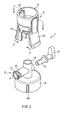
- FIG. 3 is an exploded perspective view of the connector 1. As shown in FIG. 3 , the connector 1 can be disassembled into a connector main body 2, a first connecting portion 3, and a stopcock 5. The connector main body 2 is integral with a second connecting portion 6.
- the portion denoted by reference numeral 2 in FIG. 3 is referred to as the connector main body 2.
- the connector main body 2 and the first connecting portion 3 connected thereto may be collectively regarded as the connector main body 2.
- the first connecting portion 3 is integrally provided with a hollow cylindrical connecting port 11 and lever locks 12.
- the first connecting portion 3 is a connector for connecting the connector 1 to the drug solution bag 10 ( FIG. 1 ).
- a hollow cylindrical port portion 41 ( FIG. 10 ) fixed to the drug solution bag 10 is inserted into the connecting port 11.
- the connector main body 2 includes an axial tubular portion 15 and a horizontal tubular portion 16 intersecting with each other.
- a thread 17 is formed on the horizontal tubular portion 16 for the purpose of screwing to the syringe 30 ( FIG. 2 ).
- the cylindrical stopcock 5 is inserted into the horizontal tubular portion 16. When a lever 8 is rotated, the stopcock 5 rotates around an axis of the horizontal tubular portion 16.
- the connector main body 2 is integral with the second connecting portion 6.
- the second connecting portion 6 is for connecting the connector main body 2 to the vial 20.
- a hollow cylindrical connecting port 49 ( FIG. 4 ) is formed in the second connecting portion 6.
- a cap portion of the vial 20 is fitted into the connecting port 49 of the second connecting portion 6. Details of this connection will be described later with reference to FIGS. 12 and 13 .
- FIG. 4 is an exploded perspective view of the connector 1 as seen from a different angle from that of FIG. 3 .
- FIG. 4 shows a back side of the first connecting portion 3 and the connector main body 2.
- a connecting tubular portion 21 is formed on the back side of the first connecting portion 3.
- the first connecting portion 3 can be connected to the connector main body 2 by fitting an outer circumferential surface of this connecting tubular portion 21 to an inner circumferential surface ( FIG. 3 ) of the axial tubular portion 15 of the connector main body 2.
- a needle-like portion 22 is formed on the back side of the connector main body 2.
- the needle-like portion 22 has a sharp tip, and a rubber stopper 23 ( FIG. 5 ) of the vial 20 can be pierced with the needle-like portion 22.
- FIG. 5 shows a cross-sectional view of the connector 1.
- This cross-sectional view corresponds to a vertical cross-sectional view of the connector 1 and its peripheral portions shown in FIG. 2 .
- the port portion 41 is attached to a leading end portion of a connecting port 40 attached to the drug solution bag 10.
- the port portion 41 is inserted in the connecting port 11 of the first connecting portion 3.
- the claw portions 13 ( FIG. 3 ) of the lever locks 12 that are integral with the first connecting portion 3 are engaged with the end face 41a of the port portion 41 to connect the first connecting portion 3 to the port portion 41 ( FIG. 11 ). As described above, details of this connection will be described later with reference to FIGS. 10 and 11 .
- the first connecting portion 3 has an upright tubular portion 25 formed in a central portion of the connecting port 11.
- a leading end portion of the upright tubular portion 25 pushes up a septum (a partition) 42 attached to the port portion 41.
- the septum 42 is made of a soft material, and a slit is formed therein.
- the leading end portion of the upright tubular portion 25 forces the slit of the septum 42 open by pushing up the septum 42.
- an inner space of the connecting port 40 is in communication with inner spaces 28 of the upright tubular portion 25 and the connecting tubular portion 21.
- the outer circumferential surface of the connecting tubular portion 21 of the first connecting portion 3 is fitted to the inner circumferential surface of the axial tubular portion 15 of the connector main body 2.
- the first connecting portion 3 is connected to the connector main body 2.
- the stopcock 5 is inserted in the horizontal tubular portion 16 of the connector main body 2. One end of the horizontal tubular portion 16 is sealed with the stopcock 5, and an open portion 4 ( FIGS. 3 and 4 ) is formed at the other end of the horizontal tubular portion 16.
- a first flow channel 33 which is an L-shaped flow channel, is formed in the stopcock 5, and an opening 35 formed on a leading end side of the stopcock 5 is in communication with an opening 34 formed in a side face of the stopcock 5.
- a second flow channel 36 which is a penetrating flow channel that passes through the stopcock 5 in a radial direction thereof, is formed in the stopcock 5.
- the first flow channel 33 is a flow channel having an L shape.
- the opening 34 and the opening 35 are in communication with each other, and the shape of the flow channel is not limited to an L shape.
- a first hole 37 and a second hole 43 are formed in the connector main body 2. These two holes are both holes that bring an inner space 16a of the horizontal tubular portion 16 into communication with an external space of the connector main body 2.
- the first hole 37 passes through a side wall portion of the horizontal tubular portion 16, and the second hole 43 passes through a base portion 18 and the needle-like portion 22.
- a third hole 38 and a fourth hole 44 are formed in the connector main body 2. These two holes are also holes that bring the inner space 16a of the horizontal tubular portion 16 into communication with the external space of the connector main body 2 as is the case with the first hole 37 and the second hole 43.
- the third hole 38 passes through the side wall portion of the horizontal tubular portion 16, and the fourth hole 44 passes through the base portion 18 and the needle-like portion 22.
- the stopcock 5 rotates around the axis of the horizontal tubular portion 16. Due to this rotation, the opening 34 rotationally moves in an outer circumferential direction of the stopcock 5.
- the first flow channel 33 communicates with the second hole 43.
- the second flow channel 36 communicates with the second hole 38 and the fourth hole 44.
- the first flow channel 33 can be set to a state in which it communicates with the first hole 37.
- the opening of the vial 20 is sealed with the rubber stopper 23 and a cap 24.
- the rubber stopper 23 is press-fitted in the opening of the vial 20.
- the cap 24 is formed by, for example, processing a sheet metal, and covers the opening of the vial 20.
- the vial 20 and the connector main body 2 are connected to each other by the second connecting portion 6. Details of this connection will be described later with reference to FIGS. 12 and 13 .
- FIGS. 6 to 9 an operating procedure during injection of the drug in the vial 20 into the drug solution bag 10 will be described with reference to FIGS. 6 to 9 .
- the connecting port 40, the port portion 41, the syringe 30, and the vial 20 in FIG. 5 are shown simplified in chain double-dashed lines for clarity of illustration.
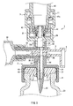
- FIG. 6 is a cross-sectional view showing a state in which the solvent in the drug solution bag 10 is drawn into the syringe 30 from the connecting port 40.
- the stopcock 5 is in the setting that brings the opening 34 of the first flow channel 33 into communication with the first hole 37. Accordingly the solvent in the drug solution bag 10 can flow to the inner space 16a of the horizontal tubular portion 16 through the connecting port 40, the inner spaces 28 of the upright tubular portion 25 and the connecting tubular portion 21, the first hole 37, the first flow channel 33, and the opening 35.
- an amount of the solvent corresponding to the amount by which the piston 31 is pulled is drawn into the syringe 30.
- the amount of the solvent to be drawn into the syringe 30 can be adjusted by adjusting the amount by which the piston 31 is pulled while looking at a scale on the cylinder 32. That is to say, a required amount of the solvent can be drawn into the syringe 30 with precision.
- FIG. 6 shows an example in which a hydrophobic filter 39 is provided in the second flow channel 36.
- the hydrophobic filter has air permeability and allows air, but not liquid, to pass through. Therefore, even when the pressure in the vial 20 is not positive, it is possible to prevent the solvent in the drug solution bag 10 from directly flowing into the vial 20.
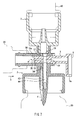
- FIG. 7 is a cross-sectional view showing a state in which the solvent that has been drawn into the syringe 30 is injected into the vial 20.
- the setting of the stopcock 5 shown in FIG. 7 is different from that in FIG. 6 .
- the stopcock 5 has been rotated by rotating the lever 8 from the state shown in FIG. 6 .
- the opening 34 of the stopcock 5 is positioned on the upper side, whereas in FIG. 7 , the opening 34 is positioned on the lower side. That is to say, in FIG. 7 , the stopcock 5 is in the setting that brings the first flow channel 33 into communication with the second hole 43.
- an amount of the solvent corresponding to the amount by which the piston 31 is pushed flows out of the syringe 30.
- the amount of the solvent to be caused to flow out of the syringe 30 can be adjusted by adjusting the amount by which the piston 31 is pushed while looking at the scale on the cylinder 32. That is to say, a required amount of the solvent can be injected into the vial 20 with precision.
- the solvent is injected into the vial 20, the drug in powder form contained in the vial 20 is dissolved in the solvent. It is possible to accelerate the dissolution by shaking the vial 20.
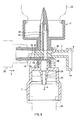
- FIG. 8 is a cross-sectional view showing a state in which the drug solution that has been generated within the vial 20 by dissolving the drug in powder form is drawn into the syringe 30.
- the vertical relationship between the connecting port 40 of the drug solution bag 10 and the vial 20 is inverted with respect to that shown in FIGS. 6 and 7 . That is to say, in FIGS. 6 and 7 , the vial 20 is positioned on the lower side, whereas in FIG. 8 , the vial 20 is positioned on the upper side.
- the drug solution in the vial 20 can flow to the inner space 16a of the horizontal tubular portion 16 through the second hole 43 and the first flow channel 33.
- an amount of the drug solution corresponding to the amount by which the piston 31 is pulled is drawn into the syringe 30. Therefore, the amount of the drug solution to be drawn into the syringe 30 can be adjusted by adjusting the amount by which the piston 31 is pulled while looking at the scale on the cylinder 32. That is to say, a required amount of the drug solution can be drawn into the syringe 30 with precision.
- FIG. 9 is a cross-sectional view showing a state in which the drug solution that has been drawn into the syringe 30 is injected into the drug solution bag 10.
- the vertical relationship between the drug solution bag 10 and the vial 20 is the same as that in the state shown in FIG. 8 , and the vial 20 remains positioned on the upper side.
- the setting of the stopcock 5 is different from that in FIG. 8 .
- the stopcock 5 has been rotated by rotating the lever 8 from the state shown in FIG. 8 .
- the opening 34 of the stopcock 5 is positioned on the upper side, whereas in FIG. 9 , the opening 34 is positioned on the lower side. That is to say, in FIG. 9 , the stopcock 5 is in the setting that brings the first flow channel 33 into communication with the first hole 37.
- an amount of the drug solution corresponding to the amount by which the piston 31 is pushed is injected into the drug solution bag 10. Therefore, the amount of the drug solution to be injected into the drug solution bag 10 can be adjusted by adjusting the amount by which the piston 31 is pushed while looking at the scale on the cylinder 32. That is to say, a required amount of the drug solution can be injected into the drug solution bag 10 with precision.
- a required amount of the drug solution can be injected into the drug solution bag 10 through the process as described above.
- the drug solution in the drug solution bag 10 will be administered into the body via a tube with a needle with which a port portion 60 ( FIG. 1 ) is pierced.
- the syringe 30 and the connector main body 2 are separate components.
- a configuration in which the cylinder portion 32 of the syringe 30 and the connector main body 2 are integral with each other also may be employed.
- the cylinder portion 32 and the connector main body 2 may be integral with each other, the cylinder portion 32 may be molded integrally with the horizontal tubular portion 16 ( FIG. 3 ), or the cylinder portion 32 may be fixed to the horizontal tubular portion 16 ( FIG. 3 ) with an adhesive.
- This configuration eliminates the need for attachment of the syringe 30 and facilitates assembly of the connector 1 prior to operation. Moreover, erroneous detachment of the syringe 30 and resulting opening of the other end of the horizontal tubular portion 16 can be prevented.
- the lever 8 extended from the stopcock 5 is formed on the stopcock 5. It is possible to determine the status of the flow channel setting within the connector 1 from the orientation of the lever 8.
- the first hole 37 and the first flow channel 33 are in communication with each other.
- a leading end 8a of the lever 8 points to an external space side communicating with the first hole 37, that is, the connecting port 40 side.
- the second hole 43 and the first flow channel 33 are in communication with each other.
- the leading end 8a of the lever 8 points to an external space side communicating with the second hole 43, that is, the vial 20 side.
- the orientation of the leading end 8a of the lever 8 may be reversed from that of the example shown in FIG. 6 .
- the leading end 8a of the lever 8 in FIG. 6 will point to the vial 20 side
- the leading end 8a of the lever 8 in FIG. 7 will point to the connecting port 40 side of the drug solution bag 10.
- the leading end 8a of the lever 8 indicates the side on which liquid flow is stopped. Therefore, in this case, it is possible to readily determine which of the drug solution bag 10 side and the vial 20 side the connector 1 stops liquid transfer to/from by observing the orientation of the leading end 8a of the lever 8.
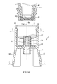
- FIG. 10 is a cross-sectional view showing a state before the first connecting portion 3 is connected to the drug solution bag 10.
- the connecting port 40 is attached to the drug solution bag 10.
- the port portion 41 is attached to the leading end portion of the connecting port 40.
- the septum (the partition) 42 in which a slit 45 is formed is attached to the port portion 41.
- the first connecting portion 3 shown in FIG. 10 corresponds to a cross-sectional view taken along line BB in FIG. 3 .
- the lever locks 12 are integral with the first connecting portion 3. Bending the lower portions of the lever locks 12 toward a central axis 11a of the connecting port 11 (the direction of arrow "c") causes the claw portions 13 of the lever locks 12 to be displaced away from the central axis 11a of the connecting port 11 (the direction of arrow "h").
- FIG. 11 is a cross-sectional view showing a state in which the first connecting portion 3 has been connected to the port portion 41.
- the port portion 41 is inserted in the connecting port 11, and also the claw portions 13 of the lever locks 12 are engaged with the end face 41a of the port portion 41.
- the lower portions of the lever locks 12 are bent toward the central axis 11a of the connecting port 11 (the direction of arrow "c"), and thus, the claw portions 13 of the lever locks 12 are displaced away from the central axis 11a of the connecting port 11 (the direction of arrow "h"). Accordingly, once the port portion 41 is inserted into the connecting port 11, the claw portions 13 engage the end face 41a of the port portion 41 as shown in FIG. 11 .
- the upright tubular portion 25 that is integral with the first connecting portion 3 is covered with a shield 26 that can open and close by extension and retraction.
- a slit 27 is formed in the shield 26.
- the shield 26 covers the upright tubular portion 25, whereas in the state shown in FIG. 11 , the shield 26 is retracted, and the upright tubular portion 25 extends outside the shield 26. This is because during insertion of the port portion 41 into the connecting port 11, a lower portion of the port portion 41 presses against the shield 26 such that the shield is pushed down.
- a leading end portion of the upright tubular portion 25 extending outside the shield 26 pushes up the septum 42 attached to the port portion 41 and thus forces the slit 45 ( FIG. 10 ) of the septum 42 open.
- the inner space of the connecting port 40 is brought into communication with the inner spaces 28 of the upright tubular portion 25 and the connecting tubular portion 21.
- the first connecting portion 3 that is integral with the vial 20 is to be detached from the port portion 41.
- the lower portions of the lever locks 12 can be pressed against toward the central axis 11a of the connecting port 11 (the direction of arrow "c"), and the claw portions 13 of the lever locks 12 displaced away from the central axis 11a of the connecting port 11 (the direction of arrow "h").
- the first connecting portion 3 returns to the state shown in FIG. 10 after being detached from the port portion 41.
- the retracted shield 26 has been restored and covers the upright tubular portion 25 again. In this state, leakage of the drug solution in the vial 20 is prevented.
- the structure of the upright tubular portion 25 covered with the shield 26 may be provided on the port portion 41 side.
- the structure of the port portion 41 in which the opening is covered with the septum 42 that can open and close by extension and retraction will be provided in the first connecting portion 3.
- FIG. 11 although the vertical relationship between the upright tubular portion 25 and the septum 42 is inverted, the fact remains that the inner space of the connecting port 40 is brought into communication with the inner space 28 of the connecting tubular portion 21.
- first connecting portion 3 of the present embodiment is merely an example, and various types of connecting systems can be employed. Furthermore, although an example in which the first connecting portion 3 and the connector main body 2 are configured as separate components has been described, a configuration in which the first connecting portion 3 and the connector main body 2 are integrally molded is conceivable depending on the structure of the first connecting portion 3.
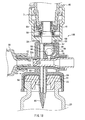
- FIG. 12 is a cross-sectional view showing a state before the second connecting portion 6 is connected to the vial 20.
- the opening of the vial 20 is sealed with the cap 24 via the rubber stopper 23.
- An opening 50 is formed in a central portion of the cap 24. Thus, the rubber stopper 23 is exposed at the position of the opening 50.
- a protrusion 46 protruding from an inner circumferential surface of the connecting port 49 is formed in the connecting port 49 of the second connecting portion 6.
- An expanded-diameter portion 47 is formed on the opening side of the vial 20. As will be described later by means of FIG. 13 , the protrusion 46 of the second connecting portion 6 is to be engaged with the expanded-diameter portion 47 of the vial 20.
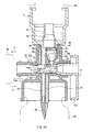
- FIG. 13 is a cross-sectional view showing a state in which the second connecting portion 6 has been connected to the vial 20.
- An inner circumferential surface of the second connecting portion 6 and an outer circumferential surface of the cap 24 of the vial 20 are fitted to each other.
- slits 48 are formed in a side wall portion of the second connecting portion 6 and facilitate fitting of the second connecting portion 6 to the vial 20.
- the rubber stopper 23 of the vial 20 is pierced with the needle-like portion 22 that is integral with the connector main body 2.
- the protrusion 46 of the second connecting portion 6 is engaged with the expanded-diameter portion 47 of the vial 20, and this prevents the second connecting portion 6 from falling off the vial 20.
- the second connecting portion 6 is not provided with a mechanism that facilitates disconnection, such as the lever locks 12. For this reason, once the second connecting portion 6 is firmly fitted to the vial 20, the second connecting portion 6 can be prevented from readily falling off the vial 20. Thus, leakage of the drug solution due to easy detachment of the vial 20 can be prevented.
- the upright tubular portion 25 is covered with the shield 26. Therefore, leakage of the drug solution from the upright tubular portion 25 is prevented even after detachment of the first connecting portion 3 from the drug solution bag.
- the drug leakage preventing structure as described above is particularly effective in the case where the drug in the vial 20 is a highly toxic drug such as an anticancer agent.
- the second connecting portion 6 of the present embodiment is merely an example, and various types of connecting systems can be employed. Moreover, although the second connecting portion 6 is formed integrally with the connector main body 2, the second connecting portion 6 may be configured as a component separate from the connector main body 2 as long as a structure that prevents the second connecting portion 6 from readily falling off the connector main body 2 can be achieved.
- Embodiment 2 of the present invention will be described with reference to the drawings.
- the portions having the same configuration as those of Embodiment 1 are denoted by the same reference numerals, and detailed descriptions thereof are omitted.
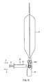
- FIG. 14 is a diagram showing an example of use of a connector 100 according to Embodiment 2 of the present invention.
- the drug solution bag 10 and the vial 20 are connected to each other via the connector 100.
- FIG. 15 shows the example in FIG. 14 as seen from the direction of arrow A.
- the syringe 30 is attached to the connector 100.
- pushing the piston 31 in the direction of arrow "a” can cause a liquid in the cylinder 32 to be ejected from the leading end of the cylinder 32.
- pulling the piston 31 in the direction of arrow "b” can cause a liquid to be drawn into the cylinder 32.
- FIG. 16 is an exploded perspective view of the connector 100. As shown in FIG. 16 , the connector 100 can be disassembled into a connector main body 101, the first connecting portion 3, and a stopcock 70. The connector main body 101 is integral with the second connecting portion 6.
- the portion denoted by reference numeral 101 in FIG. 16 is referred to as the connector main body 101.
- the connector main body 101 and the first connecting portion 3 connected thereto may be regarded collectively as the connector main body 101.
- the first connecting portion 3 is a connector for connecting the connector 100 to the drug solution bag 10 ( FIG. 14 ).
- the first connecting portion 3 has the same basic configuration as the first connecting portion 3 of Embodiment 1, even though they are partly different in shape. Connection of the first connecting portion 3 to the drug solution bag 10 is the same as described in Embodiment 1 by means of FIGS. 10 and 11 .
- the connector main body 101 includes an axial tubular portion 51 and a horizontal tubular portion 52 intersecting with each other.
- a thread 53 is formed on the horizontal tubular portion 52 for the purpose of screwing to the syringe 30 ( FIG. 15 ).
- the cylindrical stopcock 70 is inserted into the horizontal tubular portion 52. When a lever 71 is rotated, the stopcock 70 rotates around an axis of the horizontal tubular portion 52.
- the connector 100 in a connected state as shown in FIG. 15 , transfers a liquid between the drug solution bag 10 and the vial 20 via the syringe 30.
- By rotating the stopcock 70 ( FIG. 16 ) it is possible to switch between the setting that allows liquid transfer between the drug solution bag 10 and the syringe 30 and the setting that allows liquid transfer between the vial 20 and the syringe 30. Details of this switching will be described later with reference to FIGS. 19 to 22 .
- the connector main body 101 is integral with the second connecting portion 6.
- the second connecting portion 6 is for connecting the connector main body 101 to the vial 20.
- the second connecting portion 6 has the same basic configuration as the second connecting portion 6 of Embodiment 1, even though they are partly different in shape.
- the cap portion of the vial 20 is fitted into the connecting port 49 ( FIG. 17 ) of the second connecting portion 6. Details of this connection are the same as described in Embodiment 1 by means of FIGS. 12 and 13 .
- FIG. 17 is an exploded perspective view of the connector 100 as seen from a different angle from that of FIG. 16 .
- FIG. 17 shows a back side of the first connecting portion 3 and the connector main body 101.
- a connecting tubular portion 54 is formed on the back side of the first connecting portion 3.
- the first connecting portion 3 can be connected to the connector main body 101 by fitting an outer circumferential surface of this connecting tubular portion 54 to an inner circumferential surface ( FIG. 16 ) of the axial tubular portion 51 of the connector main body 101.
- a needle-like portion 80 is formed on the back side of the connector main body 101.
- the needle-like portion 80 has a sharp tip, and the rubber stopper 23 ( FIG. 18 ) of the vial 20 can be pierced with the needle-like portion 80.
- a first flow channel 72 and a second flow channel 73 are formed in the stopcock 70.
- the first flow channel 72 and the second flow channel 73 are also shown in cross-sectional views in FIGS. 19 to 22 .
- the first flow channel 72 is a recess formed in a side face of the stopcock 70, and this recess extends to a leading end face of the stopcock 70. Thus, a notch is formed in the leading end face of the stopcock 70.
- the ends of the second flow channel 73 are located at mutually different positions both in an axial direction and in a circumferential direction of the stopcock 70, as shown in FIGS. 16 , 17 , and 19 .
- a recess formed into a spiral shape is described as an example.
- FIG.18 shows a cross-sectional view of the connector 100.
- This cross-sectional view corresponds to a vertical cross-sectional view of the connector 100 and its peripheral portions shown in FIG. 15 .
- the first connecting portion 3 is connected to the port portion 41 that is attached to the leading end portion of the connecting port 40 attached to the drug solution bag 10. Details of this connection are the same as described in Embodiment 1 with reference to FIGS. 10 and 11 .
- the outer circumferential surface of the connecting tubular portion 54 of the first connecting portion 3 is fitted to the inner circumferential surface of the axial tubular portion 51 of the connector main body 101.
- the first connecting portion 3 is connected to the connector main body 101.
- the stopcock 70 is inserted in the horizontal tubular portion 52 of the connector main body 101.
- One end of the horizontal tubular portion 52 is sealed with the stopcock 70, and an open portion 57 ( FIGS. 16 and 17 ) is formed at the other end of the horizontal tubular portion 52.
- a first hole 58 and a second hole 59 are formed in the connector main body 101. These two holes are both holes that bring an inner space 52a of the horizontal tubular portion 52 into communication with an external space of the connector main body 101.
- the first hole 58 passes through a side wall portion of the horizontal tubular portion 52, and the second hole 59 passes through a base portion 63 and the needle-like portion 80.
- a third hole 60 and a fourth hole 61 are formed in the connector main body 101. These two holes are also holes that bring the inner space 52a of the horizontal tubular portion 52 into communication with the external space of the connector main body 101 as is the case with the first hole 58 and the second hole 59.
- the third hole 60 passes through the side wall portion of the horizontal tubular portion 52, and the fourth hole 61 passes through the base portion 63 and the needle-like portion 80.
- a check valve 64 is provided in the third hole 60.
- the check valve 64 includes a ball 65, an inclined surface 66, and an inclined surface 68 that is formed in a cap 67.
- the ball 65 is in contact with the inclined surface 66 under its own weight.
- liquid transfer through the third hole 60 and the fourth hole 61 is stopped, so that the flow of the solvent moving from the drug solution bag 10 side toward the vial 20 side is stopped.
- the lever 71 ( FIGS. 16 and 17 ) is formed on the stopcock 70.
- the lever 71 When the lever 71 is rotated, it rotates around the axis of the horizontal tubular portion 52. Integrally with this rotation, the first flow channel 72 and the second flow channel 73 ( FIGS. 16 and 17 ) formed in the stopcock 70 also rotate.
- This switching between the settings can be used to transfer a solvent in the drug solution bag 10 into the vial 20 to generate a drug solution by dissolving a drug in powder form contained in the vial 20 in the solvent, and afterward to inject this drug solution into the drug solution bag 10.
- FIGS. 19 to 22 an operating procedure during injection of the drug in the vial 20 into the drug solution bag 10 will be described with reference to FIGS. 19 to 22 .
- the connecting port 40, the port portion 41, the syringe 30, and the vial 20 in FIG. 18 are shown simplified in chain double-dashed lines for clarity of illustration.
- FIG. 19 is a cross-sectional view showing a state in which the solvent in the drug solution bag 10 is drawn into the syringe 30 from the connecting port 40.
- the stopcock 70 is in the setting that brings the first hole 58 into communication with the inner space 52a of the horizontal tubular portion 52 via the first flow channel 72 in the stopcock 70. Accordingly, the solvent in the drug solution bag 10 can flow to the inner space 52a of the horizontal tubular portion 52 through the connecting port 40, an inner space 56 of an upright tubular portion 55, the first hole 58, and the first flow channel 72.
- an amount of the solvent corresponding to the amount by which the piston 31 is pulled is drawn into the syringe 30. Therefore, the amount of the solvent to be drawn into the syringe 30 can be adjusted by adjusting the amount by which the piston 31 is pulled while looking at the scale on the cylinder 32. That is to say, a required amount of the solvent can be drawn into the syringe 30 with precision.
- FIG. 20 is a cross-sectional view showing a state in which the solvent that has been drawn into the syringe 30 is injected into the vial 20.
- the setting of the stopcock 70 shown in FIG. 20 is different from that in FIG. 19 .
- the stopcock 70 has been rotated by rotating the lever 71 from the state shown in FIG. 19 . Due to the rotation of the stopcock 70, the first flow channel 72 that is integral with the stopcock 70 also moves rotationally In FIG. 19 , the first flow channel 72 is positioned on the upper side, whereas in FIG. 20 , the first flow channel 72 is positioned on the lower side. That is to say, in FIG. 20 , the stopcock 70 is in the setting that brings the inner space 52a of the horizontal tubular portion 52 into communication with the second hole 59 via the first flow channel 72.
- the second flow channel 73 that is integral with the stopcock 70 also moves rotationally.
- both of the ends of the second flow channel 73 are obstructed by an inner circumferential surface of the horizontal tubular portion 52, whereas in FIG. 20 , the ends of the second flow channel 73 communicate with the third hole 60 and the fourth hole 61, respectively.
- an amount of the solvent corresponding to the amount by which the piston 31 is pushed flows out of the syringe 30.
- the amount of the solvent to be caused to flow out of the syringe 30 can be adjusted by adjusting the amount by which the piston 31 is pushed while looking at the scale on the cylinder 32. That is to say, a required amount of the solvent can be injected into the vial 20 with precision.
- air in the vial 20 passes up through the fourth hole 61 and flows into the drug solution bag 10 via the second flow channel 73, the third hole 60, and the inner space 56 of the upright tubular portion 55.
- the air that has flowed into the third hole 60 pushes up the ball 65, so that the air can flow from the third hole 60 toward the upright tubular portion 55 side.
- the check valve 64 that is provided in the third hole 60 prevents the solvent from directly flowing into the vial 20 without passing through the syringe 30 even in the case where the syringe 30 is operated erroneously.
- FIG. 21 is a cross-sectional view showing a state in which the drug solution that has been generated within the vial 20 by dissolving the drug in powder form is drawn into the syringe 30.
- the vertical relationship between the connecting port 40 of the drug solution bag 10 and the vial 20 is inverted with respect to that shown in FIGS. 19 and 20 . That is to say, in FIGS. 19 and 20 , the vial 20 is positioned on the lower side, whereas in FIG. 21 , the vial 20 is positioned on the upper side.
- the drug solution in the vial 20 can flow to the inner space 52a of the horizontal tubular portion 52 through the second hole 59 and the first flow channel 72.
- an amount of the drug solution corresponding to the amount by which the piston 31 is pulled is drawn into the syringe 30. Therefore, the amount of the drug solution to be drawn into the syringe 30 can be adjusted by adjusting the amount by which the piston 31 is pulled while looking at the scale on the cylinder 32. That is to say, a required amount of the drug solution can be drawn into the syringe 30 with precision.
- air in the drug solution bag 10 passes up through the third hole 60 and flows into the vial 20 via the second flow channel 73 and the fourth hole 61.
- the air that has flowed into the third hole 60 pushes up the ball 65, so that the air can flow from the third hole 60 toward the second flow channel 73 side.
- the check valve 64 that is provided in the third hole 60 prevents the drug solution from directly flowing into the drug solution bag 10 without passing through the syringe 30 even in the case where the syringe 30 is erroneously operated.
- FIG. 22 is a cross-sectional view showing a state in which the drug solution that has been drawn into the syringe 30 is injected into the drug solution bag 10.
- the vertical relationship between the drug solution bag 10 and the vial 20 is the same as that in the state shown in FIG. 21 , and the vial 20 remains positioned on the upper side.
- the setting of the stopcock 70 is different from that in FIG. 21 .
- the stopcock 70 has been rotated by rotating the lever 71 from the state shown in FIG. 21 .
- the first flow channel 72 is positioned on the upper side
- the first flow channel 72 is positioned on the lower side. That is to say, in FIG. 22 , the stopcock 70 is in the setting that brings the first flow channel 72 into communication with the first hole 58.
- an amount of the drug solution corresponding to the amount by which the piston 31 is pushed is injected into the drug solution bag 10. Therefore, the amount of the drug solution to be injected into the drug solution bag 10 can be adjusted by adjusting the amount by which the piston 31 is pushed while looking at the scale on the cylinder 32. That is to say, a required amount of the drug solution can be injected into the drug solution bag 10 with precision.
- a required amount of the drug solution can be injected into the drug solution bag 10 through the process as described above.
- the drug solution in the drug solution bag 10 will be administered into the body via a tube with a needle with which the port portion 60 ( FIG. 14 ) is pierced.
- the lever 71 extended from the stopcock 70 is formed on the stopcock 70. It is possible to determine the status of the flow channel setting within the connector 100 from the orientation of the lever 71.
- the orientation of the leading end 71a of the lever 71 may be reversed from that of the example shown in FIG. 19 .
- the leading end 71a of the lever 71 in FIG. 19 will point to the connecting port 40 side of the drug solution bag 10
- the leading end 71a of the lever 71 in FIG. 20 will point to the vial 20 side. That is to say, the leading end 71a of the lever 71 indicates the side on which liquid transfer is enabled. Accordingly, in this case, it is possible to readily determine which of the drug solution bag 10 side and the vial 20 side the connector 100 enables transfer to/from by observing the orientation of the leading end 71a of the lever 71.
- Embodiments 1 and 2 two types of the first and second flow channels formed in the stopcock have been described.
- one of the first flow channel and the second flow channel of Embodiment 1 may be replaced with the flow channel of Embodiment 2.
- one of the first flow channel and the second flow channel of Embodiment 2 may be replaced with the flow channel of Embodiment 1.
- the first flow channel 33 of Embodiment 1 is described as an L-shaped flow channels this L-shaped flow channel may be replaced with a groove-like flow channel like the first flow channel 72 of Embodiment 2.
- the check valve 64 includes the ball 65, the inclined surface 66, and the inclined surface 68 has been described.
- other structures may be employed.
- the check valve 64 can be provided in at least one of the third hole 60 and the fourth hole 61.
- the connector according to the present invention is capable of injecting a required amount of drug solution into a drug solution bag with precision and, therefore, is useful as, in particular, a medical connector that can be interposed between a drug solution bag and a vial to inject a pharmaceutical preparation in the vial into the drug solution bag.
Landscapes
- Health & Medical Sciences (AREA)
- Pharmacology & Pharmacy (AREA)
- Life Sciences & Earth Sciences (AREA)
- Animal Behavior & Ethology (AREA)
- General Health & Medical Sciences (AREA)
- Public Health (AREA)
- Veterinary Medicine (AREA)
- Medical Preparation Storing Or Oral Administration Devices (AREA)
- Infusion, Injection, And Reservoir Apparatuses (AREA)
Abstract
One end of a tubular portion (16) is sealed with a stopcock (5) that is fitted in the tubular portion (16). A first flow channel (33) and a second flow channel (36) are formed in the stopcock (5). A first hole (37), a second hole (43), a third hole (38), and a fourth hole (44) are formed in a connector main body (2). Switching between a setting that brings an inner space (16a) of the tubular portion (16) into communication with the first hole (37) via the first flow channel (33) and a setting that brings the inner space (16a) of the tubular portion (16) into communication with the second hole (43) via the first flow channel (33) and brings the third hole (38) into communication with the fourth hole (44) via the second flow channel (36) can be achieved by rotating the stopcock (5).
Description
- The present invention relates to a connector that is capable of switching flow channels, and particularly relates to a medical connector for transferring a liquid between, for example, a drug solution bag and a vial.
- Drugs such as anticancer agents may be stored in the form of powder for storage stability and may be dissolved before use. In this case, a solvent is injected into a vial containing a drug, and a drug solution generated by dissolving the drug in the solvent is injected into a drug solution bag. Then, the drug solution in the drug solution bag is administered into the body via a tube attached to the drug solution bag. For example, the below-listed
Patent Documents -
Patent Document 1 proposes that a mouth portion of a container (a vial) containing a drug is pierced with one end of a double-ended needle and a mouth portion of a container (a drug solution bag) containing a diluent is pierced with the other end of the double-ended needle, and in this state, a drug solution generated by dissolution in the drug-containing container is injected into the diluent-containing container. At this time, air is fed into the drug-containing container by supplying air with a syringe (an air supply means and drawing means) connected to the double-ended needle so that the drug solution is transferred quickly from the drug-containing container into the diluent-containing container. -
Patent Document 2 proposes that a stopper of a glass bottle (a vial) is pierced with a bottle needle formed in a transfer device and a stopper of an empty bag (a drug solution bag) is pierced with a hollow needle, and in this state, a fluid contained in the glass bottle is transferred into the empty bag. At this time, external air is fed into the glass bottle by operating a pump provided in the transfer device so that the drug solution in the glass bottle can be transferred smoothly into the empty bag. -
- Patent Document 1:
JP 2002-238979A - Patent Document 2:
JP S56-95247U - However, the amount of drug solution to be injected into the drug solution bag differs from patient to patient, and there have been cases where it is necessary to adjust the amount of drug solution to be injected so as to be appropriate for individual patients. According to the devices proposed in
Patent Documents Patent Documents - The present invention has been made to solve conventional problems such as those described above, and it is an object thereof to provide a connector that is capable of injecting a required amount of drug solution into a drug solution bag with precision.
- In order to achieve the above-described object, a connector of the present invention is a connector including a connector main body provided with a tubular portion and a stopcock that is fitted in the tubular portion so as to be rotatable around an axis of the tubular portion, wherein one end of the tubular portion is sealed with the stopcock that is fitted in the tubular portion; a first flow channel and a second flow channel are formed in the stopcock; a first hole, a second hole, a third hole, and a fourth hole are formed in the connector main body; the first, the second, the third, and the fourth holes are holes that bring an inner space of the tubular portion into communication with an external space of the connector main body; and switching between a setting that brings the inner space of the tubular portion into communication with the first hole via the first flow channel and a setting that brings the inner space of the tubular portion into communication with the second hole via the first flow channel and brings the third hole into communication with the fourth hole via the second flow channel can be achieved by rotating the stopcock.
- With the connector of the present invention, it is possible to inject a required amount of drug solution into a drug solution bag with precision.
-
-
FIG. 1 is a diagram showing an example of use of aconnector 1 according toEmbodiment 1 of the present invention. -
FIG. 2 is a diagram showing the example inFIG. 1 as seen from the direction of arrow A. -
FIG. 3 is an exploded perspective view of theconnector 1 according toEmbodiment 1 of the present invention. -
FIG. 4 is an exploded perspective view of theconnector 1 inFIG. 3 as seen from a different angle from that ofFIG. 3 . -
FIG. 5 is a cross-sectional view of theconnector 1 according toEmbodiment 1 of the present invention. -
FIG. 6 is a cross-sectional view showing a state in which a solvent in adrug solution bag 10 is drawn into asyringe 30 from a connectingport 40, according toEmbodiment 1 of the present invention. -
FIG. 7 is a cross-sectional view showing a state in which the solvent that has been drawn into thesyringe 30 is injected into avial 20, according toEmbodiment 1 of the present invention. -
FIG. 8 is a cross-sectional view showing a state in which a drug solution that has been generated within thevial 20 is drawn into thesyringe 30, according toEmbodiment 1 of the present invention. -
FIG. 9 is a cross-sectional view showing a state in which the drug solution that has been drawn into thesyringe 30 is injected into thedrug solution bag 10, according toEmbodiment 1 of the present invention. -
FIG. 10 is a cross-sectional view showing a state before a first connectingportion 3 according to an embodiment of the present invention is connected to thedrug solution bag 10. -
FIG. 11 is a cross-sectional view showing a state in which the first connectingportion 3 according to the embodiment of the present invention has been connected to aport portion 41. -
FIG. 12 is a cross-sectional view showing a state before a second connectingportion 6 according to the embodiment of the present invention is connected to thevial 20. -
FIG. 13 is a cross-sectional view showing a state in which the second connectingportion 6 according to the embodiment of the present invention has been connected to thevial 20. -
FIG. 14 is a diagram showing an example of use of aconnector 100 according toEmbodiment 2 of the present invention. -
FIG. 15 is a diagram showing the example inFIG. 14 as seen from the direction of arrow A. -
FIG. 16 is an exploded perspective view of theconnector 100 according toEmbodiment 2 of the present invention. -
FIG. 17 is an exploded perspective view of theconnector 100 inFIG. 16 as seen from a different angle from that ofFIG. 16 . -
FIG. 18 is a cross-sectional view of theconnector 100 according toEmbodiment 2 of the present invention. -
FIG. 19 is a cross-sectional view showing a state in which a solvent in the drug solution bag is drawn into thesyringe 30 from the connectingport 40, according toEmbodiment 2 of the present invention. -
FIG. 20 is a cross-sectional view showing a state in which the solvent that has been drawn into thesyringe 30 is injected into thevial 20, according toEmbodiment 2 of the present invention. -
FIG. 21 is a cross-sectional view showing a state in which a drug solution that has been generated within thevial 20 is drawn into thesyringe 30, according toEmbodiment 2 of the present invention. -
FIG. 22 is a cross-sectional view showing a state in which the drug solution that has been drawn into thesyringe 30 is injected into thedrug solution bag 10, according toEmbodiment 2 of the present invention. - According to the present invention, when a syringe, a drug solution bag, and a vial are connected to the connector, it is possible to transfer a liquid between the vial and the drug solution bag via the syringe by switching between the flow channel settings within the connector, and it is also possible to adjust accurately the amount of the liquid to be transferred. Thus, a required amount of drug solution can be injected into the drug solution bag with precision.
- In the connector of the present invention, it is preferable that a first connecting portion and a second connecting portion are provided in the connector main body; connecting ports are formed in the first and the second connecting portions; the first and the third holes are in communication with a space in the first connecting portion; and the second and the fourth holes are in communication with a space on the connecting port side of the second connecting portion. This configuration facilitates connection of the connector to the drug solution bag and the vial.
- Moreover, it is preferable that the first flow channel is a recess formed in a side face of the stopcock, the recess extending to a leading end face of the stopcock and forming a notch in the leading end face of the stopcock. With this configuration, a flow channel can be formed between the recess and an inner circumferential surface of the tubular portion.
- Moreover, it is preferable that both ends of the second flow channel are located at mutually different positions in an axial direction and in a circumferential direction of the stopcock. With this configuration, the state in which the ends of the second flow channel respectively communicate with the third hole and the fourth hole can be changed to the state in which the second flow channel is not interposed between the third hole and the fourth hole by rotating the stopcock. Thus, it is possible to switch between the state in which transfer between the third hole and the fourth hole is possible and the state in which transfer between the third hole and the fourth hole is not possible by rotating the stopcock.
- Moreover, it is preferable that the second flow channel is a recess formed in a side face of the stopcock so as to have a spiral shape.
- Moreover, it is preferable that the first flow channel is a hole that brings an opening formed on a leading end side of the stopcock into communication with an opening formed in a side face of the stopcock.
- Moreover, it is preferable that the second flow channel is a penetrating flow channel that passes through the stopcock in a radial direction of the stopcock.
- Moreover, it is preferable that a check valve is provided in at least one of the third hole and the fourth hole, and when the stopcock is set to the setting that brings the third hole into communication with the fourth hole via the second flow channel, liquid transfer through the third hole and the fourth hole is stopped by the check valve. With this configuration, when the syringe, the drug solution bag, and the vial are connected to the connector, it is possible to prevent a liquid from being transferred between the drug solution bag and the vial without passing through the syringe even in the case where the syringe is erroneously operated.
- Moreover, it is preferable that the first connecting portion includes a lever lock that is integral with the connecting port formed in the first connecting portion. This configuration facilitates attachment and detachment of the first connecting portion.
- Moreover, it is preferable that the second connecting portion has a protrusion protruding from an inner circumferential surface of the connecting port formed in the second connecting portion. With this configuration, it is possible to prevent the second connecting portion from falling off.
- Moreover, it is preferable that the first connecting portion has a portion covered with a shield that can open and close by extension and retraction. With this configuration, leakage of the drug solution from the first connecting portion can be prevented even after the first connecting portion has been detached from the drug solution bag. Therefore, if the vial is disposed of in a state in which the second connecting portion and the vial remain in the connected state, leakage of the drug in the vial will be prevented.
- Moreover, it is preferable that a graduated syringe including a cylinder and a movable piston is formed integrally on the other end side of the tubular portion. This configuration facilitates assembly of the connector prior to operation. Moreover, erroneous detachment of the syringe and resulting opening of the other end of the tubular portion can be prevented.
- Moreover, it is preferable that a lever extended from the stopcock is formed on the stopcock, and the lever is disposed in such a manner that when the stopcock is set to the setting that brings the inner space of the tubular portion into communication with the first hole via the first flow channel, a leading end of the extended lever points to an external space side communicating with the first hole, and when the stopcock is set to the setting that brings the inner space of the tubular portion into communication with the second hole via the first flow channel, the leading end of the extended lever points to an external space side communicating with the second hole. With this configuration, it is possible to determine the status of the flow channel setting within the connector from the orientation of the lever.
- Moreover, it is preferable that a lever extended from the stopcock is formed on the stopcock, and the lever is disposed in such a manner that when the stopcock is set to the setting that brings the inner space of the tubular portion into communication with the first hole via the first flow channel, a leading end of the extended lever points to an external space side communicating with the second hole, and when the stopcock is set to the setting that brings the inner space of the tubular portion into communication with the second hole via the first flow channel, the leading end of the extended lever points to an external space side communicating with the first hole. With this configuration, it is possible to determine the status of the flow channel setting within the connector from the orientation of the lever.
- Moreover, it is preferable that a hydrophobic filter is provided in at least one of the third hole, the penetrating flow channel, and the fourth hole. With this configuration, when the syringe, the drug solution bag, and the vial are connected to the connector, liquid transfer between the drug solution bag and the vial via the third hole, the penetrating flow channel, and the fourth hole reliably can be prevented.
This also renders accurate adjustment of the amount of liquid to be transferred between the vial and the drug solution bag via the syringe more reliable. - Hereinafter, embodiments of the present invention will be described with reference to the drawings.
-
FIG. 1 is a diagram showing an example of use of aconnector 1 according toEmbodiment 1 of the present invention. In the example in this diagram, adrug solution bag 10 and avial 20 are connected to each other via theconnector 1. Thedrug solution bag 10 is formed by shaping a soft resin sheet into a pouch-like shape. Thedrug solution bag 10 can be formed by, for example, superposing two resin sheets over each other and joining their peripheral edge portions together by heat welding or the like. Thevial 20 is a container containing a drug and is, for example, a glass bottle whose opening is sealed with a rubber stopper and a cap. -
FIG. 2 shows the example inFIG. 1 as seen from the direction of arrow A. Asyringe 30 is attached to theconnector 1. Thesyringe 30 includes a hollowcylindrical cylinder 32 and amovable piston 31. Pushing thepiston 31 in the direction of arrow "a" can cause a liquid in thecylinder 32 to be ejected from a leading end of thecylinder 32. On the other hand, pulling thepiston 31 in the direction of arrow "b" can cause a liquid to be drawn into thecylinder 32. -
FIG. 3 is an exploded perspective view of theconnector 1. As shown inFIG. 3 , theconnector 1 can be disassembled into a connectormain body 2, a first connectingportion 3, and astopcock 5. The connectormain body 2 is integral with a second connectingportion 6. - It should be noted that in the following description, the portion denoted by
reference numeral 2 inFIG. 3 is referred to as the connectormain body 2. However, this is for the sake of convenience, and the connectormain body 2 and the first connectingportion 3 connected thereto may be collectively regarded as the connectormain body 2. - The first connecting
portion 3 is integrally provided with a hollowcylindrical connecting port 11 and lever locks 12. The first connectingportion 3 is a connector for connecting theconnector 1 to the drug solution bag 10 (FIG. 1 ). During connection to thedrug solution bag 10, a hollow cylindrical port portion 41 (FIG. 10 ) fixed to thedrug solution bag 10 is inserted into the connectingport 11. - At this time, while lower portions of the lever locks 12 are bent in the direction of arrow "c",
claw portions 13 of the lever locks 12 engage anend face 41a (FIGS. 10 and11 ) of theport portion 41. Details of the connection of the first connectingportion 3 to thedrug solution bag 10 will be described later with reference toFIGS. 10 and11 . - The connector
main body 2 includes an axialtubular portion 15 and a horizontaltubular portion 16 intersecting with each other. Athread 17 is formed on the horizontaltubular portion 16 for the purpose of screwing to the syringe 30 (FIG. 2 ). Thecylindrical stopcock 5 is inserted into the horizontaltubular portion 16. When alever 8 is rotated, thestopcock 5 rotates around an axis of the horizontaltubular portion 16. - The
connector 1, in a connected state as shown inFIG. 2 , allows liquid transfer between thedrug solution bag 10 and thevial 20 via thesyringe 30. By rotating the stopcock 5 (FIG. 3 ), it is possible to switch between a flow channel setting that allows liquid transfer between thedrug solution bag 10 and thesyringe 30 and a flow channel setting that allows liquid transfer between thevial 20 and thesyringe 30. Details of the switching will be described later with reference toFIGS. 6 to 9 . - As described above, in
FIG. 3 , the connectormain body 2 is integral with the second connectingportion 6. The second connectingportion 6 is for connecting the connectormain body 2 to thevial 20. A hollow cylindrical connecting port 49 (FIG. 4 ) is formed in the second connectingportion 6. During connection of the second connectingportion 6 to thevial 20, a cap portion of thevial 20 is fitted into the connectingport 49 of the second connectingportion 6. Details of this connection will be described later with reference toFIGS. 12 and13 . -
FIG. 4 is an exploded perspective view of theconnector 1 as seen from a different angle from that ofFIG. 3 .FIG. 4 shows a back side of the first connectingportion 3 and the connectormain body 2. A connectingtubular portion 21 is formed on the back side of the first connectingportion 3. The first connectingportion 3 can be connected to the connectormain body 2 by fitting an outer circumferential surface of this connectingtubular portion 21 to an inner circumferential surface (FIG. 3 ) of the axialtubular portion 15 of the connectormain body 2. - A needle-
like portion 22 is formed on the back side of the connectormain body 2. The needle-like portion 22 has a sharp tip, and a rubber stopper 23 (FIG. 5 ) of thevial 20 can be pierced with the needle-like portion 22. -
FIG. 5 shows a cross-sectional view of theconnector 1. This cross-sectional view corresponds to a vertical cross-sectional view of theconnector 1 and its peripheral portions shown inFIG. 2 . Theport portion 41 is attached to a leading end portion of a connectingport 40 attached to thedrug solution bag 10. Theport portion 41 is inserted in the connectingport 11 of the first connectingportion 3. Although not shown in this cross-sectional view, the claw portions 13 (FIG. 3 ) of the lever locks 12 that are integral with the first connectingportion 3 are engaged with theend face 41a of theport portion 41 to connect the first connectingportion 3 to the port portion 41 (FIG. 11 ). As described above, details of this connection will be described later with reference toFIGS. 10 and11 . - The first connecting
portion 3 has an uprighttubular portion 25 formed in a central portion of the connectingport 11. A leading end portion of the uprighttubular portion 25 pushes up a septum (a partition) 42 attached to theport portion 41. Theseptum 42 is made of a soft material, and a slit is formed therein. In the state shown inFIG. 5 , the leading end portion of the uprighttubular portion 25 forces the slit of theseptum 42 open by pushing up theseptum 42. Thus, an inner space of the connectingport 40 is in communication withinner spaces 28 of the uprighttubular portion 25 and the connectingtubular portion 21. - The outer circumferential surface of the connecting
tubular portion 21 of the first connectingportion 3 is fitted to the inner circumferential surface of the axialtubular portion 15 of the connectormain body 2. Thus, the first connectingportion 3 is connected to the connectormain body 2. - The
stopcock 5 is inserted in the horizontaltubular portion 16 of the connectormain body 2. One end of the horizontaltubular portion 16 is sealed with thestopcock 5, and an open portion 4 (FIGS. 3 and4 ) is formed at the other end of the horizontaltubular portion 16. Afirst flow channel 33, which is an L-shaped flow channel, is formed in thestopcock 5, and anopening 35 formed on a leading end side of thestopcock 5 is in communication with anopening 34 formed in a side face of thestopcock 5. Furthermore, asecond flow channel 36, which is a penetrating flow channel that passes through thestopcock 5 in a radial direction thereof, is formed in thestopcock 5. - It should be noted that in the present embodiment, an example in which the
first flow channel 33 is a flow channel having an L shape has been described. However, all that is required is that theopening 34 and theopening 35 are in communication with each other, and the shape of the flow channel is not limited to an L shape. - A
first hole 37 and asecond hole 43 are formed in the connectormain body 2. These two holes are both holes that bring aninner space 16a of the horizontaltubular portion 16 into communication with an external space of the connectormain body 2. Thefirst hole 37 passes through a side wall portion of the horizontaltubular portion 16, and thesecond hole 43 passes through abase portion 18 and the needle-like portion 22. - Furthermore, a
third hole 38 and afourth hole 44 are formed in the connectormain body 2. These two holes are also holes that bring theinner space 16a of the horizontaltubular portion 16 into communication with the external space of the connectormain body 2 as is the case with thefirst hole 37 and thesecond hole 43.
Thethird hole 38 passes through the side wall portion of the horizontaltubular portion 16, and thefourth hole 44 passes through thebase portion 18 and the needle-like portion 22. - When the
lever 8 is rotated, thestopcock 5 rotates around the axis of the horizontaltubular portion 16. Due to this rotation, theopening 34 rotationally moves in an outer circumferential direction of thestopcock 5. - In the state shown in
FIG. 5 , thefirst flow channel 33 communicates with thesecond hole 43. Thesecond flow channel 36 communicates with thesecond hole 38 and thefourth hole 44. By rotating thelever 8 from this state, thefirst flow channel 33 can be set to a state in which it communicates with thefirst hole 37. - That is to say, by rotating the
lever 8, it is possible to switch between a setting that brings thefirst flow channel 33 into communication with thesecond hole 43 and a setting that brings thefirst flow channel 33 into communication with thefirst hole 37. This switching between the settings can be used to transfer a solvent in thedrug solution bag 10 into thevial 20 to generate a drug solution by dissolving a drug in powder form contained in thevial 20 in the solvent, and afterward to inject this drug solution into thedrug solution bag 10. Details of this will be described later with reference toFIGS. 6 to 9 . - The opening of the
vial 20 is sealed with therubber stopper 23 and acap 24. Therubber stopper 23 is press-fitted in the opening of thevial 20. Thecap 24 is formed by, for example, processing a sheet metal, and covers the opening of thevial 20. As shown inFIG. 5 , thevial 20 and the connectormain body 2 are connected to each other by the second connectingportion 6. Details of this connection will be described later with reference toFIGS. 12 and13 . - Hereinafter, an operating procedure during injection of the drug in the
vial 20 into thedrug solution bag 10 will be described with reference toFIGS. 6 to 9 . In the drawings described below, the connectingport 40, theport portion 41, thesyringe 30, and thevial 20 inFIG. 5 are shown simplified in chain double-dashed lines for clarity of illustration. -
FIG. 6 is a cross-sectional view showing a state in which the solvent in thedrug solution bag 10 is drawn into thesyringe 30 from the connectingport 40. InFIG. 6 , thestopcock 5 is in the setting that brings theopening 34 of thefirst flow channel 33 into communication with thefirst hole 37. Accordingly the solvent in thedrug solution bag 10 can flow to theinner space 16a of the horizontaltubular portion 16 through the connectingport 40, theinner spaces 28 of the uprighttubular portion 25 and the connectingtubular portion 21, thefirst hole 37, thefirst flow channel 33, and theopening 35. - When the
stopcock 5 is in the setting shown inFIG. 6 , pulling the piston 31 (FIG. 2 ) of thesyringe 30 in the direction of arrow "b" can cause the solvent in thedrug solution bag 10 to be drawn into theinner space 16a of the horizontaltubular portion 16 and further into the syringe 30 (the direction of arrow "d"). - In this case, an amount of the solvent corresponding to the amount by which the
piston 31 is pulled is drawn into thesyringe 30. Thus, the amount of the solvent to be drawn into thesyringe 30 can be adjusted by adjusting the amount by which thepiston 31 is pulled while looking at a scale on thecylinder 32. That is to say, a required amount of the solvent can be drawn into thesyringe 30 with precision. - In the state shown in
FIG. 6 , when the pressure in thevial 20 is set to positive pressure, it is possible to prevent the solvent in thedrug solution bag 10 from going into thevial 20 through thethird hole 38, thesecond flow channel 36, and thefourth hole 44. Tb ensure this, a hydrophobic filter can be provided in at least one of thethird hole 38, thesecond flow channel 36, and thefourth hole 44.FIG. 6 shows an example in which ahydrophobic filter 39 is provided in thesecond flow channel 36. - The hydrophobic filter has air permeability and allows air, but not liquid, to pass through. Therefore, even when the pressure in the
vial 20 is not positive, it is possible to prevent the solvent in thedrug solution bag 10 from directly flowing into thevial 20. -
FIG. 7 is a cross-sectional view showing a state in which the solvent that has been drawn into thesyringe 30 is injected into thevial 20. The setting of thestopcock 5 shown inFIG. 7 is different from that inFIG. 6 . InFIG. 7 , thestopcock 5 has been rotated by rotating thelever 8 from the state shown inFIG. 6 . InFIG. 6 , theopening 34 of thestopcock 5 is positioned on the upper side, whereas inFIG. 7 , theopening 34 is positioned on the lower side. That is to say, inFIG. 7 , thestopcock 5 is in the setting that brings thefirst flow channel 33 into communication with thesecond hole 43. - In the state shown in
FIG. 7 , when the piston 31 (FIG. 2 ) of thesyringe 30 is pushed in the direction of arrow "a", the solvent in thesyringe 30 is expelled into theinner space 16a of the horizontaltubular portion 16. The solvent that has reached theinner space 16a flows in the direction of arrow "e" and passes through thefirst flow channel 33 and thesecond hole 43 to be injected into thevial 20 as indicated by arrow "f". - In this case, an amount of the solvent corresponding to the amount by which the
piston 31 is pushed flows out of thesyringe 30. Thus, the amount of the solvent to be caused to flow out of thesyringe 30 can be adjusted by adjusting the amount by which thepiston 31 is pushed while looking at the scale on thecylinder 32. That is to say, a required amount of the solvent can be injected into thevial 20 with precision. - During injection of the solvent into the
vial 20, air in thevial 20 passes up through thefourth hole 44 and flows into thedrug solution bag 10 via the connectingport 40. This also applies to the case where a hydrophobic filter is provided in the flow channel from thefourth hole 44 to thethird hole 38 as described above. That is to say, the air permeability of the hydrophobic filter allows air in thevial 20 to flow into thedrug solution bag 10. - Once the solvent is injected into the
vial 20, the drug in powder form contained in thevial 20 is dissolved in the solvent. It is possible to accelerate the dissolution by shaking thevial 20. -
FIG. 8 is a cross-sectional view showing a state in which the drug solution that has been generated within thevial 20 by dissolving the drug in powder form is drawn into thesyringe 30. InFIG. 8 , the vertical relationship between the connectingport 40 of thedrug solution bag 10 and thevial 20 is inverted with respect to that shown inFIGS. 6 and7 . That is to say, inFIGS. 6 and7 , thevial 20 is positioned on the lower side, whereas inFIG. 8 , thevial 20 is positioned on the upper side. In this arrangement, the drug solution in thevial 20 can flow to theinner space 16a of the horizontaltubular portion 16 through thesecond hole 43 and thefirst flow channel 33. - As described above, when a hydrophobic filter is provided in the flow channel from the
fourth hole 44 to thethird hole 38, it is possible to prevent the drug solution in thevial 20 from directly flowing to thedrug solution bag 10 via the connectingport 40 because the drug solution in thevial 20 does not pass through the hydrophobic filter. - When the
stopcock 5 is in the setting shown inFIG. 8 , pulling the piston 31 (FIG. 2 ) of thesyringe 30 in the direction of arrow "b" can cause the drug solution in thevial 20 to be drawn into theinner space 16a of the horizontaltubular portion 16 and further into the syringe 30 (the direction of arrow "d"). - In this case, an amount of the drug solution corresponding to the amount by which the
piston 31 is pulled is drawn into thesyringe 30. Therefore, the amount of the drug solution to be drawn into thesyringe 30 can be adjusted by adjusting the amount by which thepiston 31 is pulled while looking at the scale on thecylinder 32. That is to say, a required amount of the drug solution can be drawn into thesyringe 30 with precision. -
FIG. 9 is a cross-sectional view showing a state in which the drug solution that has been drawn into thesyringe 30 is injected into thedrug solution bag 10. InFIG. 9 , the vertical relationship between thedrug solution bag 10 and thevial 20 is the same as that in the state shown inFIG. 8 , and thevial 20 remains positioned on the upper side. InFIG. 9 , the setting of thestopcock 5 is different from that inFIG. 8 .
InFIG. 9 , thestopcock 5 has been rotated by rotating thelever 8 from the state shown inFIG. 8 . InFIG. 8 , theopening 34 of thestopcock 5 is positioned on the upper side, whereas inFIG. 9 , theopening 34 is positioned on the lower side. That is to say, inFIG. 9 , thestopcock 5 is in the setting that brings thefirst flow channel 33 into communication with thefirst hole 37. - In the state shown in
FIG. 9 , when the piston 31 (FIG. 2 ) of thesyringe 30 is pushed in the direction of arrow "a", the drug solution in thesyringe 30 is expelled into theinner space 16a of the horizontaltubular portion 16. The solvent that has reached theinner space 16a flows in the direction of arrow "e" and passes through thefirst flow channel 33 and thefirst hole 37 to reach theinner spaces 28 of the connectingtubular portion 21 and the uprighttubular portion 25. The drug that has reached theinner spaces 28 flows to the connectingport 40 as indicated by arrow "g" and is injected into thedrug solution bag 10. - In this case, an amount of the drug solution corresponding to the amount by which the
piston 31 is pushed is injected into thedrug solution bag 10. Therefore, the amount of the drug solution to be injected into thedrug solution bag 10 can be adjusted by adjusting the amount by which thepiston 31 is pushed while looking at the scale on thecylinder 32. That is to say, a required amount of the drug solution can be injected into thedrug solution bag 10 with precision. - A required amount of the drug solution can be injected into the
drug solution bag 10 through the process as described above. The drug solution in thedrug solution bag 10 will be administered into the body via a tube with a needle with which a port portion 60 (FIG. 1 ) is pierced. - In the present embodiment, an example in which the syringe 30 (
FIG. 2 ) and the connectormain body 2 are separate components has been described. However, a configuration in which thecylinder portion 32 of thesyringe 30 and the connectormain body 2 are integral with each other also may be employed. For thecylinder portion 32 and the connectormain body 2 to be integral with each other, thecylinder portion 32 may be molded integrally with the horizontal tubular portion 16 (FIG. 3 ), or thecylinder portion 32 may be fixed to the horizontal tubular portion 16 (FIG. 3 ) with an adhesive. This configuration eliminates the need for attachment of thesyringe 30 and facilitates assembly of theconnector 1 prior to operation. Moreover, erroneous detachment of thesyringe 30 and resulting opening of the other end of the horizontaltubular portion 16 can be prevented. - Moreover, in the present embodiment, as shown in
FIG. 3 , thelever 8 extended from thestopcock 5 is formed on thestopcock 5. It is possible to determine the status of the flow channel setting within theconnector 1 from the orientation of thelever 8. - Specifically, in
FIG. 6 , thefirst hole 37 and thefirst flow channel 33 are in communication with each other. Aleading end 8a of thelever 8 points to an external space side communicating with thefirst hole 37, that is, the connectingport 40 side. Thus, it is possible to determine that theconnector 1 is in a state in which it enables transfer to/from thedrug solution bag 10 side because theleading end 8a of thelever 8 points to the connectingport 40 side. - In
FIG. 7 , thesecond hole 43 and thefirst flow channel 33 are in communication with each other. Theleading end 8a of thelever 8 points to an external space side communicating with thesecond hole 43, that is, thevial 20 side. Thus, it is possible to determine that theconnector 1 is in a state in which it enables transfer to/from thevial 20 side because theleading end 8a of thelever 8 points to thevial 20 side. - That is to say, with the
stopcock 5 equipped with thelever 8 according to the present embodiment, it is possible to readily determine which of thedrug solution bag 10 side and thevial 20 side theconnector 1 enables transfer to/from by observing the orientation of theleading end 8a of thelever 8. - Moreover, the orientation of the
leading end 8a of thelever 8 may be reversed from that of the example shown inFIG. 6 . In this case, theleading end 8a of thelever 8 inFIG. 6 will point to thevial 20 side, and theleading end 8a of thelever 8 inFIG. 7 will point to the connectingport 40 side of thedrug solution bag 10. This means that theleading end 8a of thelever 8 indicates the side on which liquid flow is stopped. Therefore, in this case, it is possible to readily determine which of thedrug solution bag 10 side and thevial 20 side theconnector 1 stops liquid transfer to/from by observing the orientation of theleading end 8a of thelever 8. - Next, a structure for connecting the first connecting
portion 3 to thedrug solution bag 10 will be described with reference toFIGS. 10 and11 .FIG. 10 is a cross-sectional view showing a state before the first connectingportion 3 is connected to thedrug solution bag 10. As described above, the connectingport 40 is attached to thedrug solution bag 10. Theport portion 41 is attached to the leading end portion of the connectingport 40. The septum (the partition) 42 in which aslit 45 is formed is attached to theport portion 41. - The first connecting
portion 3 shown inFIG. 10 corresponds to a cross-sectional view taken along line BB inFIG. 3 . The lever locks 12 are integral with the first connectingportion 3. Bending the lower portions of the lever locks 12 toward acentral axis 11a of the connecting port 11 (the direction of arrow "c") causes theclaw portions 13 of the lever locks 12 to be displaced away from thecentral axis 11a of the connecting port 11 (the direction of arrow "h"). -
FIG. 11 is a cross-sectional view showing a state in which the first connectingportion 3 has been connected to theport portion 41. Theport portion 41 is inserted in the connectingport 11, and also theclaw portions 13 of the lever locks 12 are engaged with theend face 41a of theport portion 41. During insertion of theport portion 41 into the connectingport 11, inFIG. 10 , the lower portions of the lever locks 12 are bent toward thecentral axis 11a of the connecting port 11 (the direction of arrow "c"), and thus, theclaw portions 13 of the lever locks 12 are displaced away from thecentral axis 11a of the connecting port 11 (the direction of arrow "h"). Accordingly, once theport portion 41 is inserted into the connectingport 11, theclaw portions 13 engage theend face 41a of theport portion 41 as shown inFIG. 11 . - Here, in
FIG. 10 , the uprighttubular portion 25 that is integral with the first connectingportion 3 is covered with ashield 26 that can open and close by extension and retraction. Aslit 27 is formed in theshield 26. When theshield 26 is retracted, a portion where theslit 27 is formed opens (FIG. 11 ), and when the retractedshield 26 is restored, the portion where theslit 27 is formed closes (FIG. 10 ). - In the state shown in
FIG. 10 , theshield 26 covers the uprighttubular portion 25, whereas in the state shown inFIG. 11 , theshield 26 is retracted, and the uprighttubular portion 25 extends outside theshield 26. This is because during insertion of theport portion 41 into the connectingport 11, a lower portion of theport portion 41 presses against theshield 26 such that the shield is pushed down. - A leading end portion of the upright
tubular portion 25 extending outside theshield 26 pushes up theseptum 42 attached to theport portion 41 and thus forces the slit 45 (FIG. 10 ) of theseptum 42 open. As a result, the inner space of the connectingport 40 is brought into communication with theinner spaces 28 of the uprighttubular portion 25 and the connectingtubular portion 21. - Next, after a required amount of the drug solution has been injected into the
drug solution bag 10, the first connectingportion 3 that is integral with thevial 20 is to be detached from theport portion 41. During detachment, inFIG. 11 , the lower portions of the lever locks 12 can be pressed against toward thecentral axis 11a of the connecting port 11 (the direction of arrow "c"), and theclaw portions 13 of the lever locks 12 displaced away from thecentral axis 11a of the connecting port 11 (the direction of arrow "h"). - The first connecting
portion 3 returns to the state shown inFIG. 10 after being detached from theport portion 41. In the state shown inFIG. 10 , the retractedshield 26 has been restored and covers the uprighttubular portion 25 again. In this state, leakage of the drug solution in thevial 20 is prevented. - It should be noted that, in
FIG. 10 , the structure of the uprighttubular portion 25 covered with theshield 26 may be provided on theport portion 41 side. In this case, the structure of theport portion 41 in which the opening is covered with theseptum 42 that can open and close by extension and retraction will be provided in the first connectingportion 3. According to this configuration, inFIG. 11 , although the vertical relationship between the uprighttubular portion 25 and theseptum 42 is inverted, the fact remains that the inner space of the connectingport 40 is brought into communication with theinner space 28 of the connectingtubular portion 21. - Moreover, the first connecting
portion 3 of the present embodiment is merely an example, and various types of connecting systems can be employed. Furthermore, although an example in which the first connectingportion 3 and the connectormain body 2 are configured as separate components has been described, a configuration in which the first connectingportion 3 and the connectormain body 2 are integrally molded is conceivable depending on the structure of the first connectingportion 3. - Next, a structure for connecting the second connecting
portion 6 to thevial 20 will be described with reference toFIGS. 12 and13 .FIG. 12 is a cross-sectional view showing a state before the second connectingportion 6 is connected to thevial 20. The opening of thevial 20 is sealed with thecap 24 via therubber stopper 23. - An
opening 50 is formed in a central portion of thecap 24. Thus, therubber stopper 23 is exposed at the position of theopening 50. - A
protrusion 46 protruding from an inner circumferential surface of the connectingport 49 is formed in the connectingport 49 of the second connectingportion 6. An expanded-diameter portion 47 is formed on the opening side of thevial 20. As will be described later by means ofFIG. 13 , theprotrusion 46 of the second connectingportion 6 is to be engaged with the expanded-diameter portion 47 of thevial 20. -
FIG. 13 is a cross-sectional view showing a state in which the second connectingportion 6 has been connected to thevial 20. An inner circumferential surface of the second connectingportion 6 and an outer circumferential surface of thecap 24 of thevial 20 are fitted to each other. As shown inFIGS. 3 and4 , slits 48 are formed in a side wall portion of the second connectingportion 6 and facilitate fitting of the second connectingportion 6 to thevial 20. - In
FIG. 13 , therubber stopper 23 of thevial 20 is pierced with the needle-like portion 22 that is integral with the connectormain body 2. Theprotrusion 46 of the second connectingportion 6 is engaged with the expanded-diameter portion 47 of thevial 20, and this prevents the second connectingportion 6 from falling off thevial 20. - Moreover, unlike the first connecting
portion 3, the second connectingportion 6 is not provided with a mechanism that facilitates disconnection, such as the lever locks 12. For this reason, once the second connectingportion 6 is firmly fitted to thevial 20, the second connectingportion 6 can be prevented from readily falling off thevial 20. Thus, leakage of the drug solution due to easy detachment of thevial 20 can be prevented. - Moreover, after the first connecting
portion 3 has been detached from thedrug solution bag 10, as shown inFIG. 10 , the uprighttubular portion 25 is covered with theshield 26. Therefore, leakage of the drug solution from the uprighttubular portion 25 is prevented even after detachment of the first connectingportion 3 from the drug solution bag. - Thus, if the
vial 20 is disposed of in a state in which the first connectingportion 3 has been detached from thedrug solution bag 10 and the second connectingportion 6 and thevial 20 remain in the connected state, leakage of the drug in thevial 20 is prevented. - The drug leakage preventing structure as described above is particularly effective in the case where the drug in the
vial 20 is a highly toxic drug such as an anticancer agent. - It should be noted that the second connecting
portion 6 of the present embodiment is merely an example, and various types of connecting systems can be employed. Moreover, although the second connectingportion 6 is formed integrally with the connectormain body 2, the second connectingportion 6 may be configured as a component separate from the connectormain body 2 as long as a structure that prevents the second connectingportion 6 from readily falling off the connectormain body 2 can be achieved. - Hereinafter, a connector according to
Embodiment 2 of the present invention will be described with reference to the drawings. The portions having the same configuration as those ofEmbodiment 1 are denoted by the same reference numerals, and detailed descriptions thereof are omitted. -
FIG. 14 is a diagram showing an example of use of aconnector 100 according toEmbodiment 2 of the present invention. In the example shown in this diagram, thedrug solution bag 10 and thevial 20 are connected to each other via theconnector 100. -
FIG. 15 shows the example inFIG. 14 as seen from the direction of arrow A. Thesyringe 30 is attached to theconnector 100. As is the case withEmbodiment 1, pushing thepiston 31 in the direction of arrow "a" can cause a liquid in thecylinder 32 to be ejected from the leading end of thecylinder 32. On the other hand, pulling thepiston 31 in the direction of arrow "b" can cause a liquid to be drawn into thecylinder 32. -
FIG. 16 is an exploded perspective view of theconnector 100. As shown inFIG. 16 , theconnector 100 can be disassembled into a connectormain body 101, the first connectingportion 3, and astopcock 70. The connectormain body 101 is integral with the second connectingportion 6. - It should be noted that in the following description, the portion denoted by
reference numeral 101 inFIG. 16 is referred to as the connectormain body 101. However, this is for the sake of convenience, and the connectormain body 101 and the first connectingportion 3 connected thereto may be regarded collectively as the connectormain body 101. - The first connecting
portion 3 is a connector for connecting theconnector 100 to the drug solution bag 10 (FIG. 14 ). The first connectingportion 3 has the same basic configuration as the first connectingportion 3 ofEmbodiment 1, even though they are partly different in shape. Connection of the first connectingportion 3 to thedrug solution bag 10 is the same as described inEmbodiment 1 by means ofFIGS. 10 and11 . - The connector
main body 101 includes an axialtubular portion 51 and a horizontaltubular portion 52 intersecting with each other. Athread 53 is formed on the horizontaltubular portion 52 for the purpose of screwing to the syringe 30 (FIG. 15 ). Thecylindrical stopcock 70 is inserted into the horizontaltubular portion 52. When alever 71 is rotated, thestopcock 70 rotates around an axis of the horizontaltubular portion 52. - The
connector 100, in a connected state as shown inFIG. 15 , transfers a liquid between thedrug solution bag 10 and thevial 20 via thesyringe 30. By rotating the stopcock 70 (FIG. 16 ), it is possible to switch between the setting that allows liquid transfer between thedrug solution bag 10 and thesyringe 30 and the setting that allows liquid transfer between thevial 20 and thesyringe 30. Details of this switching will be described later with reference toFIGS. 19 to 22 . - As described above, in
FIG. 16 , the connectormain body 101 is integral with the second connectingportion 6. The second connectingportion 6 is for connecting the connectormain body 101 to thevial 20. The second connectingportion 6 has the same basic configuration as the second connectingportion 6 ofEmbodiment 1, even though they are partly different in shape. During connection of the second connectingportion 6 to thevial 20, the cap portion of thevial 20 is fitted into the connecting port 49 (FIG. 17 ) of the second connectingportion 6. Details of this connection are the same as described inEmbodiment 1 by means ofFIGS. 12 and13 . -
FIG. 17 is an exploded perspective view of theconnector 100 as seen from a different angle from that ofFIG. 16 .FIG. 17 shows a back side of the first connectingportion 3 and the connectormain body 101. A connectingtubular portion 54 is formed on the back side of the first connectingportion 3. The first connectingportion 3 can be connected to the connectormain body 101 by fitting an outer circumferential surface of this connectingtubular portion 54 to an inner circumferential surface (FIG. 16 ) of the axialtubular portion 51 of the connectormain body 101. - A needle-
like portion 80 is formed on the back side of the connectormain body 101. The needle-like portion 80 has a sharp tip, and the rubber stopper 23 (FIG. 18 ) of thevial 20 can be pierced with the needle-like portion 80. - As shown in
FIGS. 16 and17 , afirst flow channel 72 and asecond flow channel 73 are formed in thestopcock 70. Thefirst flow channel 72 and thesecond flow channel 73 are also shown in cross-sectional views inFIGS. 19 to 22 . Thefirst flow channel 72 is a recess formed in a side face of the stopcock 70, and this recess extends to a leading end face of thestopcock 70. Thus, a notch is formed in the leading end face of thestopcock 70. - The ends of the
second flow channel 73 are located at mutually different positions both in an axial direction and in a circumferential direction of the stopcock 70, as shown inFIGS. 16 ,17 , and19 . In the present embodiment, a recess formed into a spiral shape is described as an example. -
FIG.18 shows a cross-sectional view of theconnector 100. This cross-sectional view corresponds to a vertical cross-sectional view of theconnector 100 and its peripheral portions shown inFIG. 15 . The first connectingportion 3 is connected to theport portion 41 that is attached to the leading end portion of the connectingport 40 attached to thedrug solution bag 10. Details of this connection are the same as described inEmbodiment 1 with reference toFIGS. 10 and11 . - The outer circumferential surface of the connecting
tubular portion 54 of the first connectingportion 3 is fitted to the inner circumferential surface of the axialtubular portion 51 of the connectormain body 101. Thus, the first connectingportion 3 is connected to the connectormain body 101. - The stopcock 70 is inserted in the horizontal
tubular portion 52 of the connectormain body 101. One end of the horizontaltubular portion 52 is sealed with the stopcock 70, and an open portion 57 (FIGS. 16 and17 ) is formed at the other end of the horizontaltubular portion 52. - A
first hole 58 and asecond hole 59 are formed in the connectormain body 101. These two holes are both holes that bring aninner space 52a of the horizontaltubular portion 52 into communication with an external space of the connectormain body 101. Thefirst hole 58 passes through a side wall portion of the horizontaltubular portion 52, and thesecond hole 59 passes through abase portion 63 and the needle-like portion 80. - Furthermore, a
third hole 60 and afourth hole 61 are formed in the connectormain body 101. These two holes are also holes that bring theinner space 52a of the horizontaltubular portion 52 into communication with the external space of the connectormain body 101 as is the case with thefirst hole 58 and thesecond hole 59. Thethird hole 60 passes through the side wall portion of the horizontaltubular portion 52, and thefourth hole 61 passes through thebase portion 63 and the needle-like portion 80. - A
check valve 64 is provided in thethird hole 60. Thecheck valve 64 includes aball 65, aninclined surface 66, and aninclined surface 68 that is formed in acap 67. In the state shown inFIG. 18 , theball 65 is in contact with theinclined surface 66 under its own weight. Thus, even in a setting that brings thethird hole 60 into communication with thefourth hole 61 via thesecond flow channel 73 as shown inFIG. 20 , liquid transfer through thethird hole 60 and thefourth hole 61 is stopped, so that the flow of the solvent moving from thedrug solution bag 10 side toward thevial 20 side is stopped. - On the other hand, when the connector is inverted from the state shown in
FIG. 20 , theball 65 comes into contact with theinclined surface 68 of thecap 67 under its own weight, as shown inFIG. 21 . In this case, liquid transfer through thethird hole 60 is stopped, so that the flow of the drug solution moving from thevial 20 side toward thedrug solution bag 10 side is stopped. - Therefore, with the
check valve 64, liquid transfer through both of thethird hole 60 and thefourth hole 61 is stopped even in the setting that brings thethird hole 60 into communication with thefourth hole 61 via thesecond flow channel 73. Thus, in the case where thesyringe 30 is erroneously operated, the liquid is prevented from directly going into thedrug solution bag 10 or thevial 20 without passing through thesyringe 30. Details of this will be described later with reference toFIGS. 20 and21 . - Although not illustrated in
FIG. 18 , the lever 71 (FIGS. 16 and17 ) is formed on thestopcock 70. When thelever 71 is rotated, it rotates around the axis of the horizontaltubular portion 52. Integrally with this rotation, thefirst flow channel 72 and the second flow channel 73 (FIGS. 16 and17 ) formed in the stopcock 70 also rotate. - In the state shown in
FIG. 18 , leading end portions of the first to thefourth holes 58 to 61 on the horizontaltubular portion 52 side are obstructed by the side face of thestopcock 70. Thus, liquid transfer between theinner space 52a of the horizontaltubular portion 52 and the external space of the connectormain body 101 via the first to thefourth holes 58 to 61 is blocked. - By rotating the lever 71 (
FIGS. 16 and17 ), it is possible to switch between a setting that brings theinner space 52a of the horizontaltubular portion 52 into communication with thefirst hole 58 via the first flow channel 72 (FIGS. 16 and17 ) in thestopcock 70 and a setting that brings theinner space 52a of the horizontaltubular portion 52 into communication with thesecond hole 59 via thefirst flow channel 72 and also brings thethird hole 60 into communication with thefourth hole 61 via the second flow channel 73 (FIGS. 16 and17 ). This switching between the settings can be used to transfer a solvent in thedrug solution bag 10 into thevial 20 to generate a drug solution by dissolving a drug in powder form contained in thevial 20 in the solvent, and afterward to inject this drug solution into thedrug solution bag 10. - Hereinafter, an operating procedure during injection of the drug in the
vial 20 into thedrug solution bag 10 will be described with reference toFIGS. 19 to 22 . In the drawings described below, the connectingport 40, theport portion 41, thesyringe 30, and thevial 20 inFIG. 18 are shown simplified in chain double-dashed lines for clarity of illustration. -
FIG. 19 is a cross-sectional view showing a state in which the solvent in thedrug solution bag 10 is drawn into thesyringe 30 from the connectingport 40. InFIG. 19 , thestopcock 70 is in the setting that brings thefirst hole 58 into communication with theinner space 52a of the horizontaltubular portion 52 via thefirst flow channel 72 in thestopcock 70. Accordingly, the solvent in thedrug solution bag 10 can flow to theinner space 52a of the horizontaltubular portion 52 through the connectingport 40, aninner space 56 of an uprighttubular portion 55, thefirst hole 58, and thefirst flow channel 72. - When the stopcock 70 is in the setting shown in
FIG. 19 , pulling the piston 31 (FIG. 15 ) of thesyringe 30 in the direction of arrow "b" can cause the solvent in thedrug solution bag 10 to be drawn into theinner space 52a of the horizontaltubular portion 52 and further into the syringe 30 (the direction of arrow "d"). - In this case, an amount of the solvent corresponding to the amount by which the
piston 31 is pulled is drawn into thesyringe 30. Therefore, the amount of the solvent to be drawn into thesyringe 30 can be adjusted by adjusting the amount by which thepiston 31 is pulled while looking at the scale on thecylinder 32. That is to say, a required amount of the solvent can be drawn into thesyringe 30 with precision. - On the other hand, in the state shown in
FIG. 19 , the leading end portions of thesecond hole 59, thethird hole 60, and thefourth hole 61 on the horizontaltubular portion 52 side are obstructed by the side face of thestopcock 70. Thus, the solvent in thedrug solution bag 10 is prevented from directly flowing into thevial 20. -
FIG. 20 is a cross-sectional view showing a state in which the solvent that has been drawn into thesyringe 30 is injected into thevial 20. The setting of the stopcock 70 shown inFIG. 20 is different from that inFIG. 19 . InFIG. 20 , thestopcock 70 has been rotated by rotating thelever 71 from the state shown inFIG. 19 . Due to the rotation of the stopcock 70, thefirst flow channel 72 that is integral with the stopcock 70 also moves rotationally InFIG. 19 , thefirst flow channel 72 is positioned on the upper side, whereas inFIG. 20 , thefirst flow channel 72 is positioned on the lower side. That is to say, inFIG. 20 , thestopcock 70 is in the setting that brings theinner space 52a of the horizontaltubular portion 52 into communication with thesecond hole 59 via thefirst flow channel 72. - Moreover, due to the rotation of the stopcock 70, the
second flow channel 73 that is integral with the stopcock 70 also moves rotationally. InFIG. 19 , both of the ends of thesecond flow channel 73 are obstructed by an inner circumferential surface of the horizontaltubular portion 52, whereas inFIG. 20 , the ends of thesecond flow channel 73 communicate with thethird hole 60 and thefourth hole 61, respectively. - In the state shown in
FIG. 20 , when the piston 31 (FIG. 15 ) of thesyringe 30 is pushed in the direction of arrow "a", the solvent in thesyringe 30 is expelled into theinner space 52a of the horizontaltubular portion 52. The solvent that has reached theinner space 52a flows in the direction of arrow "e" and passes through thefirst flow channel 72 and thesecond hole 59 to be injected into thevial 20. - In this case, an amount of the solvent corresponding to the amount by which the
piston 31 is pushed flows out of thesyringe 30. Thus, the amount of the solvent to be caused to flow out of thesyringe 30 can be adjusted by adjusting the amount by which thepiston 31 is pushed while looking at the scale on thecylinder 32. That is to say, a required amount of the solvent can be injected into thevial 20 with precision. - During injection of the solvent into the
vial 20, air in thevial 20 passes up through thefourth hole 61 and flows into thedrug solution bag 10 via thesecond flow channel 73, thethird hole 60, and theinner space 56 of the uprighttubular portion 55. The air that has flowed into thethird hole 60 pushes up theball 65, so that the air can flow from thethird hole 60 toward the uprighttubular portion 55 side. - Here, in the state shown in
FIG. 20 , if the piston 31 (FIG. 15 ) of thesyringe 30 is pulled in the direction of arrow "b" instead of being pushed in the direction of arrow "a", air in thevial 20 will be drawn into thesyringe 30 via thesecond hole 59. This causes the solvent in thedrug solution bag 10 to flow so as to be drawn into thevial 20 side, that is, drawn into thethird hole 60 side. - On the other hand, in the state shown in
FIG. 20 , theball 65 is in contact with theinclined surface 66, and downward movement of theball 65 is restricted. Thus, even when the solvent flows into thethird hole 60, the flow of the solvent is stopped in thethird hole 60, so that the solvent is prevented from passing through thesecond flow channel 73 and flowing into thevial 20. - That is to say, the
check valve 64 that is provided in thethird hole 60 prevents the solvent from directly flowing into thevial 20 without passing through thesyringe 30 even in the case where thesyringe 30 is operated erroneously. -
FIG. 21 is a cross-sectional view showing a state in which the drug solution that has been generated within thevial 20 by dissolving the drug in powder form is drawn into thesyringe 30. InFIG. 21 , the vertical relationship between the connectingport 40 of thedrug solution bag 10 and thevial 20 is inverted with respect to that shown inFIGS. 19 and20 . That is to say, inFIGS. 19 and20 , thevial 20 is positioned on the lower side, whereas inFIG. 21 , thevial 20 is positioned on the upper side. In this arrangement, the drug solution in thevial 20 can flow to theinner space 52a of the horizontaltubular portion 52 through thesecond hole 59 and thefirst flow channel 72. - When the stopcock 70 is in the setting shown in
FIG. 21 , pulling the piston 31 (FIG. 15 ) of thesyringe 30 in the direction of arrow "b" can cause the drug solution in thevial 20 to be drawn into theinner space 52a of the horizontaltubular portion 52 and further into the syringe 30 (the direction of arrow "d"). - In this case, an amount of the drug solution corresponding to the amount by which the
piston 31 is pulled is drawn into thesyringe 30. Therefore, the amount of the drug solution to be drawn into thesyringe 30 can be adjusted by adjusting the amount by which thepiston 31 is pulled while looking at the scale on thecylinder 32. That is to say, a required amount of the drug solution can be drawn into thesyringe 30 with precision. - During drawing of the drug solution contained in the
vial 20 into thesyringe 30, air in thedrug solution bag 10 passes up through thethird hole 60 and flows into thevial 20 via thesecond flow channel 73 and thefourth hole 61. The air that has flowed into thethird hole 60 pushes up theball 65, so that the air can flow from thethird hole 60 toward thesecond flow channel 73 side. - Here, in the state shown in
FIG. 21 , if the piston 31 (FIG. 15 ) of thesyringe 30 is pushed in the direction of arrow "a" instead of being pulled in the direction of arrow "b", air or the drug solution will flow backward into thevial 20 via thesecond hole 59. This causes the drug solution in thevial 20 to flow so as to be expelled to thethird hole 60 side via thefourth hole 61 and thesecond flow channel 73. - On the other hand, in the state shown in
FIG. 21 , theball 65 is in contact with theinclined surface 68, and downward movement of theball 65 is restricted. Thus, even when the drug solution flows into thethird hole 60, the flow of the drug solution is stopped in thethird hole 60, so that the drug solution is prevented from flowing into thedrug solution bag 10 through thesecond flow channel 73. - That is to say, the
check valve 64 that is provided in thethird hole 60 prevents the drug solution from directly flowing into thedrug solution bag 10 without passing through thesyringe 30 even in the case where thesyringe 30 is erroneously operated. -
FIG. 22 is a cross-sectional view showing a state in which the drug solution that has been drawn into thesyringe 30 is injected into thedrug solution bag 10. InFIG. 22 , the vertical relationship between thedrug solution bag 10 and thevial 20 is the same as that in the state shown inFIG. 21 , and thevial 20 remains positioned on the upper side. InFIG. 22 , the setting of the stopcock 70 is different from that inFIG. 21 . InFIG. 22 , thestopcock 70 has been rotated by rotating thelever 71 from the state shown inFIG. 21 . InFIG. 21 , thefirst flow channel 72 is positioned on the upper side, whereas inFIG. 22 , thefirst flow channel 72 is positioned on the lower side. That is to say, inFIG. 22 , thestopcock 70 is in the setting that brings thefirst flow channel 72 into communication with thefirst hole 58. - In the state shown in
FIG. 22 , when the piston 31 (FIG. 15 ) of thesyringe 30 is pushed in the direction of arrow "a", the drug solution in thesyringe 30 is expelled into theinner space 52a of the horizontaltubular portion 52. The solvent that has reached theinner space 52a flows in the direction of arrow "e" and passes through thefirst flow channel 72 and thefirst hole 58 to reach theinner space 56 of the uprighttubular portion 55. The drug that has reached theinner space 56 flows to the connectingport 40 as indicated by arrow "g" and is injected into thedrug solution bag 10. - In this case, an amount of the drug solution corresponding to the amount by which the
piston 31 is pushed is injected into thedrug solution bag 10. Therefore, the amount of the drug solution to be injected into thedrug solution bag 10 can be adjusted by adjusting the amount by which thepiston 31 is pushed while looking at the scale on thecylinder 32. That is to say, a required amount of the drug solution can be injected into thedrug solution bag 10 with precision. - A required amount of the drug solution can be injected into the
drug solution bag 10 through the process as described above. The drug solution in thedrug solution bag 10 will be administered into the body via a tube with a needle with which the port portion 60 (FIG. 14 ) is pierced. - In the present embodiment, an example in which the syringe 30 (
FIG. 15 ) and the connectormain body 101 are separate components has been described. However, a configuration in which thecylinder portion 32 of thesyringe 30 and the connectormain body 101 are integral with each other also may be employed. This is the same asEmbodiment 1. - Moreover, in the present embodiment, as shown in
FIG. 16 , thelever 71 extended from thestopcock 70 is formed on thestopcock 70. It is possible to determine the status of the flow channel setting within theconnector 100 from the orientation of thelever 71. - Specifically, in
FIG. 19 , the end portions on the horizontaltubular portion 52 side of thesecond hole 59 and thefourth hole 61, which are positioned on thevial 20 side, are obstructed by the side face of the stopcock 70, and no liquid flows into thevial 20. Meanwhile, theleading end 71a of thelever 71 points to thevial 20 side. This means that theleading end 71a of thelever 71 indicates the side on which liquid flow is stopped. Therefore, it is possible to determine that theconnector 100 is in a setting that stops liquid transfer to thevial 20 side by observing the orientation of theleading end 71a of thelever 71. - In
FIG. 20 , the end portion on the horizontaltubular portion 52 side of thefirst hole 58, which is positioned on thedrug solution bag 10 side, is obstructed by the side face of the stopcock 70, and a liquid in thesyringe 30 does not flow to thedrug solution bag 10 side. Meanwhile, theleading end 71a of thelever 70 points to theport portion 40 side of thedrug solution bag 10. This means that theleading end 71a of thelever 71 indicates the side on which liquid flow is stopped. Accordingly, it is possible to determine that theconnector 100 is in a setting that stops liquid transfer to thedrug solution bag 10 side by observing the orientation of theleading end 71a of thelever 70. - Therefore, it is possible to determine readily which of the
drug solution bag 10 side and thevial 20 side theconnector 100 stops liquid transfer to/from by observing the orientation of theleading end 71a of thelever 71. - Moreover, the orientation of the
leading end 71a of thelever 71 may be reversed from that of the example shown inFIG. 19 . In this case, theleading end 71a of thelever 71 inFIG. 19 will point to the connectingport 40 side of thedrug solution bag 10, and theleading end 71a of thelever 71 inFIG. 20 will point to thevial 20 side. That is to say, theleading end 71a of thelever 71 indicates the side on which liquid transfer is enabled. Accordingly, in this case, it is possible to readily determine which of thedrug solution bag 10 side and thevial 20 side theconnector 100 enables transfer to/from by observing the orientation of theleading end 71a of thelever 71. - Moreover, in
Embodiments Embodiment 1 may be replaced with the flow channel ofEmbodiment 2. Also, one of the first flow channel and the second flow channel ofEmbodiment 2 may be replaced with the flow channel ofEmbodiment 1. For example, although thefirst flow channel 33 ofEmbodiment 1 is described as an L-shaped flow channels this L-shaped flow channel may be replaced with a groove-like flow channel like thefirst flow channel 72 ofEmbodiment 2. - Moreover, in the present embodiment, an example in which the
check valve 64 includes theball 65, theinclined surface 66, and theinclined surface 68 has been described. However, other structures may be employed. Furthermore, although an example in which thecheck valve 64 is provided in thethird hole 60 has been described, the check valve can be provided in at least one of thethird hole 60 and thefourth hole 61. For example, it is possible to provide the check valve in thefourth hole 61 when thefourth hole 61 has a larger diameter and a smaller check valve is used. - As described above, the connector according to the present invention is capable of injecting a required amount of drug solution into a drug solution bag with precision and, therefore, is useful as, in particular, a medical connector that can be interposed between a drug solution bag and a vial to inject a pharmaceutical preparation in the vial into the drug solution bag.
-
- 1, 100
- connector
- 2, 101
- connector main body
- 3
- first connecting portion
- 4, 57
- open portion
- 5, 70
- stopcock
- 6
- second connecting portion
- 8, 71
- lever
- 8a, 71a
- leading end of lever
- 11, 49
- connecting port
- 12
- lever lock
- 16, 52
- horizontal tubular portion (tubular portion)
- 25, 55
- upright tubular portion
- 26
- shield
- 30
- syringe
- 31
- piston
- 32
- cylinder
- 33, 72
- first flow channel
- 34,35
- opening
- 36, 73
- second flow channel
- 37, 58
- first hole
- 38, 60
- third hole
- 39
- hydrophobic filter
- 43, 59
- second hole
- 44, 61
- fourth hole
- 46
- protrusion
- 64
- check valve
Claims (15)
- A connector comprising a connector main body provided with a tubular portion and a stopcock that is fitted in the tubular portion so as to be rotatable around an axis of the tubular portion,
wherein one end of the tubular portion is sealed with the stopcock that is fitted in the tubular portion,
a first flow channel and a second flow channel are formed in the stopcock,
a first hole, a second hole, a third hole, and a fourth hole are formed in the connector main body,
the first, the second, the third, and the fourth holes are holes that bring an inner space of the tubular portion into communication with an external space of the connector main body, and
switching between a setting that brings the inner space of the tubular portion into communication with the first hole via the first flow channel and a setting that brings the inner space of the tubular portion into communication with the second hole via the first flow channel and brings the third hole into communication with the fourth hole via the second flow channel can be achieved by rotating the stopcock. - The connector according to claim 1,
wherein a first connecting portion and a second connecting portion are provided in the connector main body,
connecting ports are formed in the first and the second connecting portions, the first and the third holes are in communication with a space in the first connecting portion, and
the second and the fourth holes are in communication with a space on the connecting port side of the second connecting portion. - The connector according to claim 1, wherein the first flow channel is a recess formed in a side face of the stopcock, the recess extending to a leading end face of the stopcock and forming a notch in the leading end face of the stopcock.
- The connector according to claim 1, wherein both ends of the second flow channel are located at mutually different positions in an axial direction and in a circumferential direction of the stopcock.
- The connector according to claim 4, wherein the second flow channel is a recess formed in a side face of the stopcock so as to have a spiral shape.
- The connector according to claim 1, wherein the first flow channel is a hole that brings an opening formed on a leading end side of the stopcock into communication with an opening formed in a side face of the stopcock.
- The connector according to claim 1, wherein the second flow channel is a penetrating flow channel that passes through the stopcock in a radial direction of the stopcock.
- The connector according to claim 1,
wherein a check valve is provided in at least one of the third hole and the fourth hole, and
when the stopcock is set to the setting that brings the third hole into communication with the fourth hole via the second flow channel, liquid transfer through the third hole and the fourth hole is stopped by the check valve. - The connector according to claim 2, wherein the first connecting portion comprises a lever lock that is integral with the connecting port formed in the first connecting portion.
- The connector according to claim 2, wherein the second connecting portion has a protrusion protruding from an inner circumferential surface of the connecting port formed in the second connecting portion.
- The connector according to claim 2, wherein the first connecting portion has a portion covered with a shield that can open and close by extension and retraction.
- The connector according to claim 1, wherein a graduated syringe comprising a cylinder and a movable piston is integrally formed on the other end side of the tubular portion.
- The connector according to claim 1,
wherein a lever extended from the stopcock is formed on the stopcock, and the lever is disposed in such a manner that:when the stopcock is set to the setting that brings the inner space of the tubular portion into communication with the first hole via the first flow channel, a leading end of the extended lever points to an external space side communicating with the first hole, andwhen the stopcock is set to the setting that brings the inner space of the tubular portion into communication with the second hole via the first flow channel, the leading end of the extended lever points to an external space side communicating with the second hole. - The connector according to claim 1,
wherein a lever extended from the stopcock is formed on the stopcock, and
the lever is disposed in such a manner that:when the stopcock is set to the setting that brings the inner space of the tubular portion into communication with the first hole via the first flow channel, a leading end of the extended lever points to an external space side communicating with the second hole, andwhen the stopcock is set to the setting that brings the inner space of the tubular portion into communication with the second hole via the first flow channel, the leading end of the extended lever points to an external space side communicating with the first hole. - The connector according to claim 7, wherein a hydrophobic filter is provided in at least one of the third hole, the penetrating flow channel, and the fourth hole.
Applications Claiming Priority (2)
| Application Number | Priority Date | Filing Date | Title |
|---|---|---|---|
| JP2008299994 | 2008-11-25 | ||
| PCT/JP2009/069392 WO2010061743A1 (en) | 2008-11-25 | 2009-11-13 | Connector |
Publications (1)
| Publication Number | Publication Date |
|---|---|
| EP2351550A1 true EP2351550A1 (en) | 2011-08-03 |
Family
ID=42225621
Family Applications (1)
| Application Number | Title | Priority Date | Filing Date |
|---|---|---|---|
| EP20090828991 Withdrawn EP2351550A1 (en) | 2008-11-25 | 2009-11-13 | Connector |
Country Status (5)
| Country | Link |
|---|---|
| US (1) | US8506548B2 (en) |
| EP (1) | EP2351550A1 (en) |
| JP (1) | JP5557040B2 (en) |
| CN (1) | CN102223866B (en) |
| WO (1) | WO2010061743A1 (en) |
Cited By (6)
| Publication number | Priority date | Publication date | Assignee | Title |
|---|---|---|---|---|
| WO2014066249A1 (en) * | 2012-10-22 | 2014-05-01 | Creaturo Michael A | Apparatus and method for mixing a medicament and supplying it to an intravenous fluid |
| WO2014006552A3 (en) * | 2012-07-05 | 2014-07-31 | Lior Raday | Syringe extension |
| WO2014177347A1 (en) * | 2013-05-03 | 2014-11-06 | Hubertus Goller Gesellschaft M.B.H. | Transfer device |
| EP2881138A4 (en) * | 2012-08-01 | 2016-05-18 | Jms Co Ltd | INFUSION ASSEMBLY AND METHOD FOR USING THE SAME |
| WO2020168175A1 (en) | 2019-02-15 | 2020-08-20 | Yukon Medical, Llc | Transfer device for use with infusion liquid container |
| EP4412575A1 (en) * | 2021-10-04 | 2024-08-14 | sfm medical devices GmbH | Transfer apparatus having an opening cover |
Families Citing this family (104)
| Publication number | Priority date | Publication date | Assignee | Title |
|---|---|---|---|---|
| US6695817B1 (en) | 2000-07-11 | 2004-02-24 | Icu Medical, Inc. | Medical valve with positive flow characteristics |
| US20060161115A1 (en) | 2004-11-05 | 2006-07-20 | Fangrow Thomas F | Soft-grip medical connector |
| US7547300B2 (en) | 2006-04-12 | 2009-06-16 | Icu Medical, Inc. | Vial adaptor for regulating pressure |
| US7883499B2 (en) | 2007-03-09 | 2011-02-08 | Icu Medical, Inc. | Vial adaptors and vials for regulating pressure |
| WO2010022095A1 (en) | 2008-08-20 | 2010-02-25 | Icu Medical, Inc. | Anti-reflux vial adaptors |
| CN102196798B (en) * | 2008-11-25 | 2014-04-09 | 株式会社Jms | Connector |
| US8454579B2 (en) | 2009-03-25 | 2013-06-04 | Icu Medical, Inc. | Medical connector with automatic valves and volume regulator |
| CN104873389B (en) | 2009-07-29 | 2017-12-05 | Icu医学有限公司 | Fluid conveying device and application method |
| IL201323A0 (en) | 2009-10-01 | 2010-05-31 | Medimop Medical Projects Ltd | Fluid transfer device for assembling a vial with pre-attached female connector |
| IL202070A0 (en) | 2009-11-12 | 2010-06-16 | Medimop Medical Projects Ltd | Inline liquid drug medical device |
| BR112012020829B1 (en) | 2010-02-24 | 2020-04-14 | Medimop Medical Projects Ltd | liquid drug transfer device for use with a medical bottle |
| WO2011104711A1 (en) | 2010-02-24 | 2011-09-01 | Medimop Medical Projects Ltd | Fluid transfer assembly with venting arrangement |
| USD644731S1 (en) | 2010-03-23 | 2011-09-06 | Icu Medical, Inc. | Medical connector |
| US8758306B2 (en) | 2010-05-17 | 2014-06-24 | Icu Medical, Inc. | Medical connectors and methods of use |
| US20130079744A1 (en) | 2010-07-12 | 2013-03-28 | Jms Co., Ltd. | Drug solution delivery device for medical use |
| IL209102A0 (en) * | 2010-11-04 | 2011-01-31 | Medimop Medical Projects Ltd | Inline liquid drug medical device with handle operated flow control member |
| IL209290A0 (en) | 2010-11-14 | 2011-01-31 | Medimop Medical Projects Ltd | Inline liquid drug medical device having rotary flow control member |
| EP2462913A1 (en) * | 2010-12-10 | 2012-06-13 | Fresenius Medical Care Deutschland GmbH | Insert and vial for the infusion of liquids |
| IL212420A0 (en) | 2011-04-17 | 2011-06-30 | Medimop Medical Projects Ltd | Liquid drug transfer assembly |
| JP6140916B2 (en) | 2011-06-08 | 2017-06-07 | 株式会社ジェイ・エム・エス | Medical male parts |
| JP6541349B2 (en) | 2011-08-18 | 2019-07-10 | アイシーユー・メディカル・インコーポレーテッド | Pressure control vial adapter |
| HK1199851A1 (en) | 2011-09-21 | 2015-07-24 | Bayer Healthcare Llc | Continuous multi-fluid pump device, drive and actuating system and method |
| IL215699A0 (en) | 2011-10-11 | 2011-12-29 | Medimop Medical Projects Ltd | Liquid drug reconstitution assemblage for use with iv bag and drug vial |
| JP5584368B2 (en) * | 2011-10-26 | 2014-09-03 | パナソニック株式会社 | Chemical solution transfer method and chemical solution transfer device |
| HK1203861A1 (en) | 2011-12-22 | 2015-12-18 | Icu医学有限公司 | Fluid transfer devices and methods of use |
| MX352988B (en) | 2012-01-13 | 2017-12-15 | Icu Medical Inc | Pressure-regulating vial adaptors and methods. |
| ES2416855B1 (en) * | 2012-01-30 | 2014-10-06 | Biotechnology Institute, I Mas D, S.L. | Adapter device to reduce or eliminate possible bacterial contamination in a process of extracting or transferring blood components from a container |
| US9585812B2 (en) | 2012-02-07 | 2017-03-07 | Yukon Medical, Llc | Transfer device with fluid filter |
| USD720451S1 (en) | 2012-02-13 | 2014-12-30 | Medimop Medical Projects Ltd. | Liquid drug transfer assembly |
| USD737436S1 (en) | 2012-02-13 | 2015-08-25 | Medimop Medical Projects Ltd. | Liquid drug reconstitution assembly |
| JP5907379B2 (en) | 2012-02-15 | 2016-04-26 | 株式会社ジェイ・エム・エス | Medical male cover |
| AU2013204180B2 (en) | 2012-03-22 | 2016-07-21 | Icu Medical, Inc. | Pressure-regulating vial adaptors |
| IL219065A0 (en) | 2012-04-05 | 2012-07-31 | Medimop Medical Projects Ltd | Fluid transfer device with manual operated cartridge release arrangement |
| WO2013154050A1 (en) | 2012-04-13 | 2013-10-17 | 株式会社ジェイ・エム・エス | Male connector equipped with lock mechanism |
| JP6094829B2 (en) | 2012-04-13 | 2017-03-15 | 株式会社ジェイ・エム・エス | Male connector with locking mechanism |
| JP5896228B2 (en) * | 2012-04-26 | 2016-03-30 | 株式会社ジェイ・エム・エス | Medical connector |
| IL221634A0 (en) | 2012-08-26 | 2012-12-31 | Medimop Medical Projects Ltd | Universal drug vial adapter |
| IL221635A0 (en) | 2012-08-26 | 2012-12-31 | Medimop Medical Projects Ltd | Drug vial mixing and transfer device for use with iv bag and drug vial |
| JP5868555B2 (en) | 2012-09-13 | 2016-02-24 | メディモップ・メディカル・プロジェクツ・リミテッド | Nested female vial adapter |
| USD734868S1 (en) | 2012-11-27 | 2015-07-21 | Medimop Medical Projects Ltd. | Drug vial adapter with downwardly depending stopper |
| EP2939648B1 (en) | 2012-12-28 | 2019-07-17 | JMS Co., Ltd. | Vial shield |
| US9089475B2 (en) | 2013-01-23 | 2015-07-28 | Icu Medical, Inc. | Pressure-regulating vial adaptors |
| DK2948125T3 (en) | 2013-01-23 | 2019-08-19 | Icu Medical Inc | PRESSURE REGULATING VAPE ADAPTERS |
| USD751190S1 (en) * | 2013-02-20 | 2016-03-08 | Nipro Corporation | Infusion bag |
| US9237986B2 (en) * | 2013-03-14 | 2016-01-19 | Carefusion 303, Inc. | Vial access cap and syringe with gravity-assisted valve |
| IL225734A0 (en) | 2013-04-14 | 2013-09-30 | Medimop Medical Projects Ltd | Ready-to-use drug vial assemblages including drug vial and drug vial closure having fluid transfer member, and drug vial closure therefor |
| BR112015027555B1 (en) | 2013-05-10 | 2022-02-01 | Medimop Medical Projects Ltd | Medical device for use with a needleless syringe, a vial and a liquid carrier to fill the needleless syringe with an injection solution for injection into a patient |
| EP3021814B1 (en) | 2013-07-19 | 2025-03-26 | ICU Medical, Inc. | Pressure-regulating fluid transfer systems and methods |
| USD767124S1 (en) | 2013-08-07 | 2016-09-20 | Medimop Medical Projects Ltd. | Liquid transfer device with integral vial adapter |
| USD765837S1 (en) | 2013-08-07 | 2016-09-06 | Medimop Medical Projects Ltd. | Liquid transfer device with integral vial adapter |
| CN205626622U (en) | 2013-08-07 | 2016-10-12 | 麦迪麦珀医疗工程有限公司 | Fluid transfer devices for use with infusion containers |
| CA2930733A1 (en) * | 2013-11-22 | 2015-05-28 | Icu Medical Inc. | Fluid transfer devices and methods of use |
| CA2931195C (en) | 2013-11-25 | 2019-09-24 | Icu Medical, Inc. | Methods and systems for filling iv bags with therapeutic fluid |
| EP3079739B1 (en) | 2013-12-11 | 2023-02-22 | ICU Medical, Inc. | Check valve |
| EP3131519B1 (en) * | 2014-04-16 | 2021-10-20 | Becton Dickinson and Company Limited | Fluid transfer device with axially and rotationally movable portion |
| JP6605511B2 (en) | 2014-06-20 | 2019-11-13 | アイシーユー・メディカル・インコーポレーテッド | Pressure adjustment vial adapter |
| DE102014213948B4 (en) * | 2014-07-17 | 2021-09-23 | B. Braun Melsungen Aktiengesellschaft | Fluid connection system for medical purposes |
| USD757933S1 (en) | 2014-09-11 | 2016-05-31 | Medimop Medical Projects Ltd. | Dual vial adapter assemblage |
| USD786427S1 (en) | 2014-12-03 | 2017-05-09 | Icu Medical, Inc. | Fluid manifold |
| USD793551S1 (en) | 2014-12-03 | 2017-08-01 | Icu Medical, Inc. | Fluid manifold |
| JP6358724B2 (en) | 2015-01-05 | 2018-07-18 | ウエスト・ファーマ.サービシーズ・イスラエル,リミテッド | Dual vial adapter assembly with easy removable pill adapter to ensure accurate use |
| RU2714926C2 (en) | 2015-01-09 | 2020-02-21 | БАЙЕР ХелсКер ЛЛСи | Multiple fluid delivery system with multi-use disposable set and features thereof |
| US10413662B2 (en) | 2015-05-14 | 2019-09-17 | Carefusion 303, Inc. | Priming apparatus and method |
| CN113143759B (en) | 2015-07-16 | 2024-01-30 | 西部制药服务以色列有限公司 | Liquid drug transfer device for secure telescopic snap-fit on an injection vial |
| USD801522S1 (en) | 2015-11-09 | 2017-10-31 | Medimop Medical Projects Ltd. | Fluid transfer assembly |
| CN115721558A (en) | 2015-11-25 | 2023-03-03 | 西部制药服务以色列有限公司 | Dual vial adapter assembly comprising a drug vial adapter having a self-sealing inlet valve |
| WO2017096072A1 (en) | 2015-12-04 | 2017-06-08 | Icu Medical, Inc. | Systems methods and components for transferring medical fluids |
| EP3397231B1 (en) | 2016-01-29 | 2022-03-02 | ICU Medical, Inc. | Pressure-regulating vial adaptors |
| JP6825210B2 (en) | 2016-03-02 | 2021-02-03 | 株式会社ジェイ・エム・エス | Puncture needle connector and connecting tube |
| IL245803A0 (en) | 2016-05-24 | 2016-08-31 | West Pharma Services Il Ltd | Dual vial adapter assemblages including vented drug vial adapter and vented liquid vial adapter |
| IL245800A0 (en) | 2016-05-24 | 2016-08-31 | West Pharma Services Il Ltd | Dual vial adapter assemblages including identical twin vial adapters |
| IL246073A0 (en) | 2016-06-06 | 2016-08-31 | West Pharma Services Il Ltd | Fluid transfer devices for use with drug pump cartridge having slidable driving plunger |
| USD851745S1 (en) | 2016-07-19 | 2019-06-18 | Icu Medical, Inc. | Medical fluid transfer system |
| ES3055345T3 (en) | 2016-07-25 | 2026-02-11 | Icu Medical Inc | Systems and components for trapping air bubbles in medical fluid transfer modules and systems |
| US10463573B2 (en) * | 2016-08-03 | 2019-11-05 | Shinva Ande Healthcare Apparatus Co., Ltd | Sealed fluid transfer device and sealed fluid transfer method |
| IL247376A0 (en) | 2016-08-21 | 2016-12-29 | Medimop Medical Projects Ltd | Syringe assembly |
| AU2017335746A1 (en) | 2016-09-30 | 2019-04-11 | Icu Medical, Inc. | Pressure-regulating vial access devices and methods |
| USD832430S1 (en) | 2016-11-15 | 2018-10-30 | West Pharma. Services IL, Ltd. | Dual vial adapter assemblage |
| IL249408A0 (en) | 2016-12-06 | 2017-03-30 | Medimop Medical Projects Ltd | A device for transporting fluids for use with an infusion fluid container and a hand tool similar to a plunger to release a vial from it |
| IL251458A0 (en) | 2017-03-29 | 2017-06-29 | Medimop Medical Projects Ltd | User actuated liquid drug transfer devices for use in ready-to-use (rtu) liquid drug transfer assemblages |
| WO2019018198A1 (en) | 2017-07-17 | 2019-01-24 | Baxter International Inc. | Daul container system for product reconstitution |
| JP6871100B2 (en) * | 2017-07-28 | 2021-05-12 | テルモ株式会社 | Medical connector attachment / detachment aid |
| US11116696B2 (en) * | 2017-08-10 | 2021-09-14 | Baxter International Inc. | Reconstitution device, system, and method to administer a drug in a moderate bolus |
| IL254802A0 (en) | 2017-09-29 | 2017-12-31 | Medimop Medical Projects Ltd | Dual vial adapter assemblages with twin vented female vial adapters |
| JP7271436B2 (en) * | 2017-11-27 | 2023-05-11 | 株式会社ヘリオス | Cellular medicine transfer method |
| JP6850400B2 (en) * | 2017-12-03 | 2021-03-31 | ウェスト ファーマ サービシーズ イスラエル リミテッド | Infusion device with telescopic bottle adapter for use with infusion container and another infusion bottle |
| USD903864S1 (en) | 2018-06-20 | 2020-12-01 | West Pharma. Services IL, Ltd. | Medication mixing apparatus |
| JP1630477S (en) | 2018-07-06 | 2019-05-07 | ||
| USD923812S1 (en) | 2019-01-16 | 2021-06-29 | West Pharma. Services IL, Ltd. | Medication mixing apparatus |
| JP1648075S (en) | 2019-01-17 | 2019-12-16 | ||
| EP3911292B1 (en) | 2019-01-18 | 2022-12-28 | West Pharma Services IL, Ltd. | Liquid transfer devices for use with intravenous (iv) bottles |
| CN113490477B (en) | 2019-01-31 | 2024-09-27 | 西医药服务以色列有限公司 | Liquid handling device |
| IT201900002745A1 (en) * | 2019-02-26 | 2020-08-26 | Adienne Pharma & Biotech Sa | "Sterilized or sterilized packaging for dispensing medicinal or nutritional substances" |
| CN113677382B (en) | 2019-04-09 | 2023-06-09 | 西医药服务以色列有限公司 | Liquid delivery device with integrated syringe |
| JP7001838B2 (en) | 2019-04-30 | 2022-01-20 | ウェスト ファーマ サービシーズ イスラエル リミテッド | Dual lumen IV liquid transfer device with spikes |
| US11311458B2 (en) * | 2019-09-11 | 2022-04-26 | B Braun Medical Inc. | Binary connector for drug reconstitution |
| BR112022013614A2 (en) * | 2020-01-09 | 2022-09-13 | Becton Dickinson Co | DRUG TRANSFER DEVICE |
| US11590057B2 (en) | 2020-04-03 | 2023-02-28 | Icu Medical, Inc. | Systems, methods, and components for transferring medical fluids |
| USD956958S1 (en) | 2020-07-13 | 2022-07-05 | West Pharma. Services IL, Ltd. | Liquid transfer device |
| EP3964189A1 (en) * | 2020-09-03 | 2022-03-09 | Teva Pharmaceuticals International GmbH | Vial adaptor with valve |
| AU2021356704A1 (en) | 2020-10-09 | 2023-06-01 | Icu Medical, Inc. | Fluid transfer device and method of use for same |
| IL305598B2 (en) | 2021-03-03 | 2026-02-01 | Equashield Medical Ltd | A tamper proof luer lock connector and a valve arrangement for an adaptor |
| JPWO2023120550A1 (en) * | 2021-12-24 | 2023-06-29 | ||
| CN119405941B (en) * | 2024-11-21 | 2025-07-29 | 北京大学第三医院(北京大学第三临床医学院) | Indwelling needle for transcranial Doppler ultrasound imaging |
Family Cites Families (36)
| Publication number | Priority date | Publication date | Assignee | Title |
|---|---|---|---|---|
| JPS5837398Y2 (en) | 1979-04-27 | 1983-08-23 | 株式会社 ミドリ十字 | Medical transfer equipment |
| JPS5695247A (en) | 1979-12-28 | 1981-08-01 | Canon Inc | Image forming device |
| US4423741A (en) | 1980-01-14 | 1984-01-03 | Plasco, Inc. | Midstream sampling of catheterized liquid flow from a body cavity and improved coupling therefor |
| US4397335A (en) * | 1981-05-26 | 1983-08-09 | Doblar Dennis D | Rotary valve especially useful in a medical system including a flow-directed venous catheter |
| US4534758A (en) * | 1983-07-15 | 1985-08-13 | Eli Lilly & Company | Controlled release infusion system |
| US4759756A (en) | 1984-09-14 | 1988-07-26 | Baxter Travenol Laboratories, Inc. | Reconstitution device |
| JPH06145B2 (en) * | 1986-02-15 | 1994-01-05 | 株式会社ニツシヨ− | Sterile dissolution solution introducing device and dissolution solution introducing method using the same |
| JPH063233Y2 (en) * | 1989-03-17 | 1994-01-26 | ジョプラックス株式会社 | Flow switch |
| US5288290A (en) * | 1991-09-25 | 1994-02-22 | Alcon Surgical, Inc. | Multi-ported valve assembly |
| US5466220A (en) * | 1994-03-08 | 1995-11-14 | Bioject, Inc. | Drug vial mixing and transfer device |
| US5647845A (en) * | 1995-02-01 | 1997-07-15 | Habley Medical Technology Corporation | Generic intravenous infusion system |
| IL114960A0 (en) | 1995-03-20 | 1995-12-08 | Medimop Medical Projects Ltd | Flow control device |
| US5810792A (en) | 1996-04-03 | 1998-09-22 | Icu Medical, Inc. | Locking blunt cannula |
| IL118497A (en) | 1996-05-30 | 2002-08-14 | Travenol Lab Israel Ltd | Fluid sampling apparatus |
| US5871110A (en) | 1996-09-13 | 1999-02-16 | Grimard; Jean-Pierre | Transfer assembly for a medicament container having a splashless valve |
| IT236233Y1 (en) * | 1997-11-26 | 2000-08-08 | Eurospital S P A | DEVICE FOR THE CONNECTION OF A PHARMACEUTICAL PRODUCT CONTAINER TO A BAG OF LIQUID PRODUCT TO CARRY OUT THE |
| US6457488B2 (en) * | 1998-01-08 | 2002-10-01 | George Loo | Stopcock having axial port for syringe twist actuation |
| WO2000000768A1 (en) * | 1998-06-29 | 2000-01-06 | Sugan Co., Ltd. | Channel switching apparatus |
| US6453956B2 (en) | 1999-11-05 | 2002-09-24 | Medtronic Minimed, Inc. | Needle safe transfer guard |
| JP2001190689A (en) * | 2000-01-14 | 2001-07-17 | Daiichi Radioisotope Labs Ltd | Flow passage changeover valve for dosing liquid medicine, liquid medicine encapsulating body, and cartridge body for dosing liquid medicine |
| JP4372310B2 (en) * | 2000-04-10 | 2009-11-25 | ニプロ株式会社 | Adapter for mixed injection |
| JP2002177392A (en) | 2000-11-08 | 2002-06-25 | West Pharmaceutical Services Inc | Safety device of syringe |
| JP2002238979A (en) | 2001-02-16 | 2002-08-27 | Jms Co Ltd | Double-ended needle |
| US6585714B2 (en) | 2001-07-26 | 2003-07-01 | Tournaire S.A. | Foolproofing device for a container such as a container intended for medical use |
| US6875205B2 (en) * | 2002-02-08 | 2005-04-05 | Alaris Medical Systems, Inc. | Vial adapter having a needle-free valve for use with vial closures of different sizes |
| EP1454650B1 (en) * | 2003-03-06 | 2007-10-10 | CSL Behring GmbH | Transfer device, in particular for medical fluids |
| US6948522B2 (en) * | 2003-06-06 | 2005-09-27 | Baxter International Inc. | Reconstitution device and method of use |
| JP3883527B2 (en) * | 2003-07-17 | 2007-02-21 | ニプロ株式会社 | Transfer needle |
| PT2463201E (en) * | 2003-10-30 | 2014-05-09 | Teva Medical Ltd | Safety drug handling device |
| ES2569208T3 (en) * | 2004-09-03 | 2016-05-09 | Elcam Medical Agricultural Cooperative Association Ltd. | Stopcock |
| JP2007215775A (en) | 2006-02-16 | 2007-08-30 | Terumo Corp | Medicine storage container and manufacturing method of medicine storage container |
| FR2898812B1 (en) | 2006-03-24 | 2008-06-13 | Technoflex Sa | LUER CONNECTOR, MEDICAL CONNECTOR AND TRANSFER SET COMPRISING SUCH A CONNECTOR |
| AU2007262025B2 (en) | 2006-06-19 | 2013-03-14 | Nipro Corporation | Drug Solution Preparation Kit |
| CN101244297B (en) | 2007-02-14 | 2010-09-08 | 丁玉英 | Automatic medicine mixing device for powder injection |
| US8434528B2 (en) | 2007-04-30 | 2013-05-07 | Medtronic Minimed, Inc. | Systems and methods for reservoir filling |
| CN102196798B (en) | 2008-11-25 | 2014-04-09 | 株式会社Jms | Connector |
-
2009
- 2009-11-13 JP JP2010540449A patent/JP5557040B2/en active Active
- 2009-11-13 WO PCT/JP2009/069392 patent/WO2010061743A1/en not_active Ceased
- 2009-11-13 CN CN200980147142.8A patent/CN102223866B/en not_active Expired - Fee Related
- 2009-11-13 US US13/121,857 patent/US8506548B2/en active Active
- 2009-11-13 EP EP20090828991 patent/EP2351550A1/en not_active Withdrawn
Non-Patent Citations (1)
| Title |
|---|
| See references of WO2010061743A1 * |
Cited By (13)
| Publication number | Priority date | Publication date | Assignee | Title |
|---|---|---|---|---|
| WO2014006552A3 (en) * | 2012-07-05 | 2014-07-31 | Lior Raday | Syringe extension |
| EP2881138A4 (en) * | 2012-08-01 | 2016-05-18 | Jms Co Ltd | INFUSION ASSEMBLY AND METHOD FOR USING THE SAME |
| US9795736B2 (en) | 2012-08-01 | 2017-10-24 | Jms Co., Ltd. | Infusion set and method for using same |
| WO2014066249A1 (en) * | 2012-10-22 | 2014-05-01 | Creaturo Michael A | Apparatus and method for mixing a medicament and supplying it to an intravenous fluid |
| US9433726B2 (en) | 2012-10-22 | 2016-09-06 | Parenteral Technologies, Llc | Methods and apparatuses for delivering medicaments to intravenous fluid |
| WO2014177347A1 (en) * | 2013-05-03 | 2014-11-06 | Hubertus Goller Gesellschaft M.B.H. | Transfer device |
| WO2020168175A1 (en) | 2019-02-15 | 2020-08-20 | Yukon Medical, Llc | Transfer device for use with infusion liquid container |
| EP3924020A4 (en) * | 2019-02-15 | 2022-11-02 | Yukon Medical, LLC | TRANSFER DEVICE FOR USE WITH INFUSION FLUID CONTAINER |
| IL285465B1 (en) * | 2019-02-15 | 2026-04-01 | Yukon Medical Llc | Transfer device for use with infusion liquid container |
| EP4412575A1 (en) * | 2021-10-04 | 2024-08-14 | sfm medical devices GmbH | Transfer apparatus having an opening cover |
| JP2024533840A (en) * | 2021-10-04 | 2024-09-12 | エスエフエム・メディカル・ディバイシイズ・ゲーエムベーハー | Transfer device having opening cover |
| AU2022359808B2 (en) * | 2021-10-04 | 2025-05-29 | Sfm Medical Devices Gmbh | Transfer apparatus having an opening cover |
| JP7775463B2 (en) | 2021-10-04 | 2025-11-25 | エスエフエム・メディカル・ディバイシイズ・ゲーエムベーハー | Transfer device with opening cover |
Also Published As
| Publication number | Publication date |
|---|---|
| US8506548B2 (en) | 2013-08-13 |
| JP5557040B2 (en) | 2014-07-23 |
| WO2010061743A1 (en) | 2010-06-03 |
| US20110178493A1 (en) | 2011-07-21 |
| CN102223866B (en) | 2014-07-02 |
| CN102223866A (en) | 2011-10-19 |
| JPWO2010061743A1 (en) | 2012-04-26 |
Similar Documents
| Publication | Publication Date | Title |
|---|---|---|
| US8506548B2 (en) | Connector | |
| US8556879B2 (en) | Connector | |
| US11612687B2 (en) | Drug delivery device | |
| JP5808512B2 (en) | Liquid agent transfer device using manual rotation for two flow communication process operations | |
| EP2190518B1 (en) | Medicament mixing and injection apparatus | |
| US8979792B2 (en) | Inline liquid drug medical devices with linear displaceable sliding flow control member | |
| JP6880026B2 (en) | Medical delivery device | |
| CN104203195A (en) | Fluid transfer devices having cartridge port with cartridge ejection arrangement | |
| JP5495006B2 (en) | connector | |
| WO2007105221A1 (en) | Fluid transfer devices for use with cartridges | |
| EP3703643B1 (en) | Container adapter and delivery assembly of a liquid to a patient | |
| CA2951967A1 (en) | Fluid transfer devices and methods of use | |
| US11865076B2 (en) | Closed system for transferring medication from a flexible container | |
| CN117940180A (en) | Medical delivery device | |
| WO2014006552A2 (en) | Syringe extension | |
| CN104363877B (en) | Containment system | |
| CN115335023B (en) | Container adapter and delivery assembly | |
| HK1159469A (en) | Connector | |
| HK40082806A (en) | Container adapter and delivery assembly | |
| HK40082806B (en) | Container adapter and delivery assembly | |
| HK1158924B (en) | Connector |
Legal Events
| Date | Code | Title | Description |
|---|---|---|---|
| PUAI | Public reference made under article 153(3) epc to a published international application that has entered the european phase |
Free format text: ORIGINAL CODE: 0009012 |
|
| 17P | Request for examination filed |
Effective date: 20110516 |
|
| AK | Designated contracting states |
Kind code of ref document: A1 Designated state(s): AT BE BG CH CY CZ DE DK EE ES FI FR GB GR HR HU IE IS IT LI LT LU LV MC MK MT NL NO PL PT RO SE SI SK SM TR |
|
| DAX | Request for extension of the european patent (deleted) | ||
| STAA | Information on the status of an ep patent application or granted ep patent |
Free format text: STATUS: THE APPLICATION HAS BEEN WITHDRAWN |
|
| 18W | Application withdrawn |
Effective date: 20131118 |