EP2350849B1 - Resource arbitration for shared-write access via persistent reservation - Google Patents
Resource arbitration for shared-write access via persistent reservation Download PDFInfo
- Publication number
- EP2350849B1 EP2350849B1 EP09814963.6A EP09814963A EP2350849B1 EP 2350849 B1 EP2350849 B1 EP 2350849B1 EP 09814963 A EP09814963 A EP 09814963A EP 2350849 B1 EP2350849 B1 EP 2350849B1
- Authority
- EP
- European Patent Office
- Prior art keywords
- node
- storage mechanism
- key
- cluster
- ownership
- Prior art date
- Legal status (The legal status is an assumption and is not a legal conclusion. Google has not performed a legal analysis and makes no representation as to the accuracy of the status listed.)
- Active
Links
- 230000002085 persistent effect Effects 0.000 title claims description 30
- 230000007246 mechanism Effects 0.000 claims description 65
- 238000000034 method Methods 0.000 claims description 22
- 230000007123 defense Effects 0.000 claims description 7
- 230000008569 process Effects 0.000 description 9
- 238000004891 communication Methods 0.000 description 8
- 238000005516 engineering process Methods 0.000 description 8
- 238000010586 diagram Methods 0.000 description 7
- 238000012545 processing Methods 0.000 description 6
- 230000006855 networking Effects 0.000 description 5
- 230000003287 optical effect Effects 0.000 description 5
- 230000002093 peripheral effect Effects 0.000 description 4
- 230000008901 benefit Effects 0.000 description 3
- 230000005055 memory storage Effects 0.000 description 3
- 230000009471 action Effects 0.000 description 2
- 239000007787 solid Substances 0.000 description 2
- 230000001419 dependent effect Effects 0.000 description 1
- 239000000284 extract Substances 0.000 description 1
- 239000000835 fiber Substances 0.000 description 1
- 239000003999 initiator Substances 0.000 description 1
- 238000012423 maintenance Methods 0.000 description 1
- 238000010926 purge Methods 0.000 description 1
- 238000012546 transfer Methods 0.000 description 1
- 230000007723 transport mechanism Effects 0.000 description 1
- 238000010200 validation analysis Methods 0.000 description 1
Images


Classifications
-
- H—ELECTRICITY
- H04—ELECTRIC COMMUNICATION TECHNIQUE
- H04L—TRANSMISSION OF DIGITAL INFORMATION, e.g. TELEGRAPHIC COMMUNICATION
- H04L67/00—Network arrangements or protocols for supporting network services or applications
- H04L67/01—Protocols
- H04L67/10—Protocols in which an application is distributed across nodes in the network
- H04L67/1097—Protocols in which an application is distributed across nodes in the network for distributed storage of data in networks, e.g. transport arrangements for network file system [NFS], storage area networks [SAN] or network attached storage [NAS]
-
- G—PHYSICS
- G06—COMPUTING; CALCULATING OR COUNTING
- G06F—ELECTRIC DIGITAL DATA PROCESSING
- G06F3/00—Input arrangements for transferring data to be processed into a form capable of being handled by the computer; Output arrangements for transferring data from processing unit to output unit, e.g. interface arrangements
- G06F3/06—Digital input from, or digital output to, record carriers, e.g. RAID, emulated record carriers or networked record carriers
- G06F3/0601—Interfaces specially adapted for storage systems
- G06F3/0602—Interfaces specially adapted for storage systems specifically adapted to achieve a particular effect
- G06F3/062—Securing storage systems
- G06F3/0622—Securing storage systems in relation to access
-
- G—PHYSICS
- G06—COMPUTING; CALCULATING OR COUNTING
- G06F—ELECTRIC DIGITAL DATA PROCESSING
- G06F11/00—Error detection; Error correction; Monitoring
- G06F11/07—Responding to the occurrence of a fault, e.g. fault tolerance
- G06F11/16—Error detection or correction of the data by redundancy in hardware
- G06F11/20—Error detection or correction of the data by redundancy in hardware using active fault-masking, e.g. by switching out faulty elements or by switching in spare elements
- G06F11/202—Error detection or correction of the data by redundancy in hardware using active fault-masking, e.g. by switching out faulty elements or by switching in spare elements where processing functionality is redundant
- G06F11/2023—Failover techniques
- G06F11/2033—Failover techniques switching over of hardware resources
-
- G—PHYSICS
- G06—COMPUTING; CALCULATING OR COUNTING
- G06F—ELECTRIC DIGITAL DATA PROCESSING
- G06F11/00—Error detection; Error correction; Monitoring
- G06F11/07—Responding to the occurrence of a fault, e.g. fault tolerance
- G06F11/16—Error detection or correction of the data by redundancy in hardware
- G06F11/20—Error detection or correction of the data by redundancy in hardware using active fault-masking, e.g. by switching out faulty elements or by switching in spare elements
- G06F11/202—Error detection or correction of the data by redundancy in hardware using active fault-masking, e.g. by switching out faulty elements or by switching in spare elements where processing functionality is redundant
- G06F11/2046—Error detection or correction of the data by redundancy in hardware using active fault-masking, e.g. by switching out faulty elements or by switching in spare elements where processing functionality is redundant where the redundant components share persistent storage
-
- G—PHYSICS
- G06—COMPUTING; CALCULATING OR COUNTING
- G06F—ELECTRIC DIGITAL DATA PROCESSING
- G06F3/00—Input arrangements for transferring data to be processed into a form capable of being handled by the computer; Output arrangements for transferring data from processing unit to output unit, e.g. interface arrangements
- G06F3/06—Digital input from, or digital output to, record carriers, e.g. RAID, emulated record carriers or networked record carriers
- G06F3/0601—Interfaces specially adapted for storage systems
- G06F3/0628—Interfaces specially adapted for storage systems making use of a particular technique
- G06F3/0629—Configuration or reconfiguration of storage systems
- G06F3/0631—Configuration or reconfiguration of storage systems by allocating resources to storage systems
-
- G—PHYSICS
- G06—COMPUTING; CALCULATING OR COUNTING
- G06F—ELECTRIC DIGITAL DATA PROCESSING
- G06F3/00—Input arrangements for transferring data to be processed into a form capable of being handled by the computer; Output arrangements for transferring data from processing unit to output unit, e.g. interface arrangements
- G06F3/06—Digital input from, or digital output to, record carriers, e.g. RAID, emulated record carriers or networked record carriers
- G06F3/0601—Interfaces specially adapted for storage systems
- G06F3/0628—Interfaces specially adapted for storage systems making use of a particular technique
- G06F3/0655—Vertical data movement, i.e. input-output transfer; data movement between one or more hosts and one or more storage devices
- G06F3/0659—Command handling arrangements, e.g. command buffers, queues, command scheduling
-
- G—PHYSICS
- G06—COMPUTING; CALCULATING OR COUNTING
- G06F—ELECTRIC DIGITAL DATA PROCESSING
- G06F3/00—Input arrangements for transferring data to be processed into a form capable of being handled by the computer; Output arrangements for transferring data from processing unit to output unit, e.g. interface arrangements
- G06F3/06—Digital input from, or digital output to, record carriers, e.g. RAID, emulated record carriers or networked record carriers
- G06F3/0601—Interfaces specially adapted for storage systems
- G06F3/0668—Interfaces specially adapted for storage systems adopting a particular infrastructure
- G06F3/067—Distributed or networked storage systems, e.g. storage area networks [SAN], network attached storage [NAS]
-
- G—PHYSICS
- G06—COMPUTING; CALCULATING OR COUNTING
- G06F—ELECTRIC DIGITAL DATA PROCESSING
- G06F3/00—Input arrangements for transferring data to be processed into a form capable of being handled by the computer; Output arrangements for transferring data from processing unit to output unit, e.g. interface arrangements
- G06F3/06—Digital input from, or digital output to, record carriers, e.g. RAID, emulated record carriers or networked record carriers
- G06F3/0601—Interfaces specially adapted for storage systems
- G06F3/0668—Interfaces specially adapted for storage systems adopting a particular infrastructure
- G06F3/0671—In-line storage system
- G06F3/0683—Plurality of storage devices
- G06F3/0689—Disk arrays, e.g. RAID, JBOD
-
- G—PHYSICS
- G06—COMPUTING; CALCULATING OR COUNTING
- G06F—ELECTRIC DIGITAL DATA PROCESSING
- G06F2209/00—Indexing scheme relating to G06F9/00
- G06F2209/50—Indexing scheme relating to G06F9/50
- G06F2209/5014—Reservation
Landscapes
- Engineering & Computer Science (AREA)
- Theoretical Computer Science (AREA)
- Physics & Mathematics (AREA)
- General Engineering & Computer Science (AREA)
- General Physics & Mathematics (AREA)
- Human Computer Interaction (AREA)
- Quality & Reliability (AREA)
- Computer Networks & Wireless Communication (AREA)
- Signal Processing (AREA)
- Information Retrieval, Db Structures And Fs Structures Therefor (AREA)
- Storage Device Security (AREA)
- Hardware Redundancy (AREA)
Description
- A server cluster is generally a group of servers (nodes) arranged such that if any server fails, the other servers of the cluster can transparently take over the work of the failed server, that is, restart its applications and thereby continue serving clients without significant interruption. This operation is generally referred to as failover, or failover clustering.
- In a cluster, each storage device (hard disk drive) is owned by one node. The owner node, if properly operating, defends ownership of the storage device against other nodes' challenges for ownership, so that another node can take over ownership if the owner fails.
- To implement such a challenge - defense model, a persistent reservations ownership algorithm is used, as described in
U.S. Patent No. 7,277,952 . However, this persistent reservations ownership algorithm implements a share-nothing model in which the node owning the disk has exclusive ownership and full access to the disk, while other nodes have read-only access. - One aspect of cluster shared storage volumes technology (described in the related patent application
US2009/0327798 A1 ) is that other healthy cluster nodes need to be able to simultaneously write to shared cluster disks. As a result, a way to grant access of the storage device to healthy nodes, while excluding any nodes that are not properly participating in the cluster, is needed. -
US 2003/065782 A1 relates to protecting resources, such as storage devices and distributed systems. Via the arbitration process, one node places a persistent reservation and obtains exclusive ownership of the resource. Once reserved, the owner maintains the ownership by checking periodically or on any access failure to determine whether the owner's persistent reservation is being challenged. If so, the owner defends against the challenge. The owner has exclusive access to the disk. At no time is exclusive access lost, even temporarily, whereby the resource is protected from access by other computing devices. Certain sectors of a disk may be protected by exclusive access, while other sectors on the same disk are not protected. Multiple initiators (nodes) can register with the same reservation key. Nodes having the same reservation key will share access rights associated with this key in the reservation table, which may allow for shared access to a drive. The distributed arbitration provides for exclusive ownership in a manner that does not allow a write to the disk when it is not supposed to be written. In general, this is accomplished by always having an exclusive owner. -
US 2004/117345 A1 relates to techniques for improving the performance of a shared-nothing database system, in which at least two of the nodes that are running the shared-nothing database system have shared access to a disk. As dictated by the shared-nothing architecture of the database system, each piece of data is still owned by only one node at any given time. However, the fact that at least some of the nodes that are running the shared-nothing database system have shared access to a disk is exploited to more efficiently rebalance and recover the shared-nothing database system. Specifically, techniques are provided for changing the ownership of data in a shared-nothing database without changing the location of the data on persistent storage. -
US 2003/120743 A1 relates to a system and method of implementing disk ownership in network storage. -
US 6 532 538 B1 relates to a method and system for supporting multiple operating systems on the same disk running on different computers at the same time. -
US 6 804 703 B1 relates to a system and method for establishing persistent reserves to nonvolatile storage in a clustered computer environment. -
US 2005/066095 A1 relates to multi-threaded write interface and methods for increasing the single file read and write throughput of a file server. -
EP 2 316 077 A2EP 2 316 077 A2 - It is the object of the present invention to improve joint usage of a storage mechanism in a server cluster environment.
- This object is solved by the subject matter of the
independent claims - Preferred embodiments are defined by the
dependent claims 2 to 4, 6 to 10 and 12 to 15. - This Summary is provided to introduce a selection of representative concepts in a simplified form that are further described below in the Detailed Description.
- Briefly, various aspects of the subject matter described herein are directed towards a technology by which an owner node in a server cluster exclusively owns a storage mechanism (e.g., disk or other storage device), yet allows non-owning nodes to have shared read and write access to the storage mechanism. In one aspect, one node comprises an owner node that maintains ownership of the storage mechanism through a persistent reservation mechanism that associates (e.g., writes) a key to a registration table associated with the storage mechanism. Non-owning nodes associate a shared key to the registration table. The owner node validates the shared keys against cluster membership data, and preempts (e.g., removes) any key deemed not valid, such that invalid nodes no longer have access to the storage mechanism.
- In one aspect, the owner node defends challenges to ownership. A non-owning node writes a challenging key to the storage mechanism, and waits for a defense time. If the owner node is properly operating, it detects the challenging key within the defense time, and preempts it to maintain ownership. If the owner node is not properly operating, the owner node is not able to defend the challenge within the defense time, whereby the challenging node becomes the new owner.
- Other advantages may become apparent from the following detailed description when taken in conjunction with the drawings.
- The present invention is illustrated by way of example and not limited in the accompanying figures in which like reference numerals indicate similar elements and in which:
-
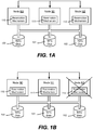
FIGURES 1A and 1B are a block diagrams representing example components in a server clustering environment with shared disks. -
FIG. 2 is a block diagram showing example components for accomplishing resource arbitration and shared-write disk access via persistent reservation. -
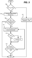
FIG. 3 is a flow diagram showing example steps taken to reserve and/or access a cluster shared volume. -
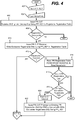
FIGS. 4 and5 comprise a flow diagram showing example steps taken to in a SCSI-environment to reserve and/or access a cluster shared volume. -
FIG. 6 shows an illustrative example of a computing environment into which various aspects of the present invention may be incorporated. - Various aspects of the technology described herein are generally directed towards allowing cluster nodes to share access to disks (e.g., configured as storage volumes) with other nodes, including sharing read and write access. In general, a storage device (alternatively referred to as a "disk" or "hard disk" herein, regardless of whether actually a disk-type storage device) is owned by a single cluster node; however as described herein, the restrictions against read and write I/O operations from other nodes are removed. This allows clustered applications and services running on any node in the cluster to access data on any shared volume.
- In one example implementation, such sharing is made possible by allowing nodes to register a SCSI Persistent Reservation (PR) key with an owned disk. More particularly, the owner node registers an exclusive PR key to assert its ownership, and the remaining nodes each register a "shared" PR key, in which is encoded an identifier of that node. In general, a shared PR key for a valid node grants that node read and write access to the disk when owned by another node. If a node that has registered a shared PR key becomes no longer valid (e.g., fails or is otherwise deemed invalid), the owner node purges that node's shared PR key, thus preventing further I/O to the disk from the invalid node.
- In one example implementation, this technology works with Microsoft® Windows® Server Failover Clustering using Microsoft® NTFS as a file system, and SCSI disks. However, it is understood that these are only examples. Indeed, other environments, file systems and/or storage technologies may be used to implement one or more aspects of the technology described herein. The present invention may be used various ways that provide benefits and advantages in computing, clustering and data access in general.
- Turning to
FIG. 1A , there is shown a simplified block diagram of a cluster environment, including three nodes, N0, N1 and N2, each owning a disk 100-102, respectively. Cluster nodes are typically connected to a cluster's disks via SCSI, Fibre Channel, ISCSI or other high-speed communication link. - Note that
FIG. 1A shows only one possible configuration, as a node may not own a disk, a node may own more than one disk, and so forth. For example, inFIG. 1B , the node N2 has failed (or failed to communicate in some way), whereby the node N0 has also taken ownership of thedisk 102 via itsreservation mechanism 110, as generally described below. The other nodes N1 and N2 have generallyidentical reservation mechanisms - In order for a node that owns a disk to provide shared access to that disk, an altered reservation scheme that allows concurrent access from multiple cluster nodes is provided. To this end, as generally represented in
FIG. 2 , each node (such as the node N1) includes a cluster disk driver 220 (e.g., cluster disk.sys comprising a kernel driver) that includes thereservation mechanism 111. As described below, a similar cluster disk driver of another node (e.g., represented by the block 222) participates in a reservation mechanism / algorithm to access thedisk 101, while the owning node's cluster disk driver N1 participates in the reservation mechanism / algorithm to maintain and protect ownership. The exemplifiedcluster disk driver 220 work with a clusterserver service component 224 as described below. - By way of background, a traditional persistent reservations ownership algorithm, described in
U.S. Patent No. 7,277,952 implements a share-nothing model, that is, the node owning the disk has exclusive ownership and full access, while other nodes have read-only access. The ownership is asserted by the owner node by placing a Write-Exclusive, registrants-only persistent reservation using a reservation key (called the PR key) into the PR reservation table on disk. The owning node maintains / defends this ownership by periodically (e.g., by default every three seconds) checking the PR registration table; other nodes challenge ownership (to take over if the owning node crashes) by registering their own keys in the PR registration table. If the owning node is operational and finds only its own PR key in the table, no action need be taken, however if it finds any key other than its own in the PR registration table, the owning node preempts that key (e.g., removes it from the table; if not operational the challenging node's key remains whereby it takes over ownership by preempting the current's owner's PR reservation with its own). Under a stable and functional cluster, the PR reservation table for a disk has one key, its PR registration table has M keys (all of them from the same owner node) where M is the number of I/O paths to the disk for MPIO systems; for non-MPIO systems M is 1. - For the disks allocated in cluster shared volume, this persistent reservation algorithm is modified as described herein to allow the nodes in the cluster to access the disk in read-write mode, essentially simultaneously, in a safe manner. Machines outside of the cluster do not have access to cluster shared volume disks.
- As generally represented in
FIG. 2 , aphysical disk resource 226 manages shared disks in a cluster, and among other actions, ensures that clustered disks are accessed safely and protected from corruption, including facilitating essentially simultaneous access the same shared disks. This is accomplished by using shared persistent reservation (PR) keys, and the knowledge of cluster membership, as described herein. - With respect to the cluster shared volume disk reservation algorithm, in one example implementation, a disk control manager 228 (e.g., of the cluster service 224) calls into the
physical disk resource 226 to set up the new reservation policy for a clustereddisk 101. More particularly, the clustereddisk 101 needs to allow read-write I/O from other nodes, yet without violating the above-described concept of ownership. To this end, the owner node retains control of the disk, but relaxes the I/O policy on a per-node basis, via a sharedPR key 230. Under this shared PR key mechanism /reservation algorithm 111, the cluster sharedvolume disk 101 in an N-node cluster has N * M keys in its registration table 240, where M is the number of I/O paths to the disk from a node in MPIO configuration; for non-MPIO systems, M is one. The owner node has M keys in the registration table 240 and one key, aPR key 231, in a reservation table 242. The tables need not be physically separate and may be kept in any manner, and indeed, the registration table may contain some indication (e.g., a flag or an ordering) as to which of its keys is "in" the reservation table 242 (which thus need not physically exist). - One aspect thus provides an algorithm to control access to a cluster disk, whereby all cluster nodes participating in a cluster have read-write access to that disk. Note that this grants read-write access on a cluster disk to all nodes in the cluster, and, while permitting read-write I/O access to other cluster nodes in good standing, it retains the safety properties of the current algorithm. It also retains liveness and performance properties, as well as the concept that a disk is owned and controlled by at most one cluster node.
- As described herein, non-owner nodes insert a shared PR key into the disk PR registration table 240. The shared key is not shared by all nodes; rather, it represents that the node inserting this key shares read-write access to the
disk 101 with other nodes. An identifier (id) of the node that inserted the key is encoded in the key. Thus, adisk 101 arbitrated by this algorithm in an N-node cluster will have N shared PR keys in its registration table 240. In one implementation, the first key is the exclusive (PR)key 231 inserted by the owner node. The remaining N-1 keys are shared PR keys inserted by non-owner nodes. - The owning node periodically queries the PR registration table 240 to evaluate the keys. If a key is a shared key, the owner extracts from the key the id of the node that inserted the key. If the node is valid (is in "good standing" in the cluster), the owner allows the key to remain in the registration table 240. If the node is not in good standing, the owner preempts the key, thus removing it from the registration table 240.
- If the key is not a shared key, then ownership has been challenged. The owner preempts such a key, thus removing it from the registration table 240.
-
FIG. 3 is a general flow diagram showing example steps of one such algorithm as implemented via the exemplified components ofFIG. 2 , for example. For any non-owner nodes such as represented viastep 300, thedisk control manager 228 requests thephysical disk resource 226 to insert a sharedPR key 230 into the registration table 240 (step 302). This key is not shared among the nodes, but rather indicates that the node that it represents shares read-write access to the disk, along with the owner node and any other nodes. An identifier (e.g., Nodeld) of the node is part of this sharedPR key 230. - On the owner node, as differentiated via
example step 300,step 304 informs thephysical disk resource 226 of the clusternode membership data 254. This may be accomplished via a simple bitmask representing the active nodes in the cluster that share the volume, (e.g., typically all nodes, but not necessarily). Thephysical disk resource 226 passes thismembership data 254 to thecluster disk driver 220. - As represented by
step 306, when thecluster disk driver 220 on the owner node sees one or more extra keys (other than its own exclusive PR key) in the registration table 240, thecluster disk driver 220 verifies the NodeId of each of those keys against thecluster membership data 254, as represented bystep 308. If the key is valid (step 310), the key is allowed to remain in the registration table 240, otherwise it is preempted (step 312). Step 314 repeats the validation for other keys; with an N-node cluster in which each node participates in shared volume access, there are N-1 such shared PR keys. -
FIGS. 4 and5 comprise an example flow diagram with additional details for a SCSI-command environment.Steps 402 and 404 are the input to the reservation mechanism of a node, comprising a PR_KEY comprising a randomly generated number and a user-configurable interval (with a default value of three seconds, for example). - Step 406 represents attempting registration, which is performed before reservation. If registration is successful (step 408), a reservation attempt is made at
step 410. If the reservation is successful, the process advances toFIG. 5 to maintain the reservation, described below. Otherwise the process branches to step 414 to perform persistent reservation arbitration. - Step 414 reads the registration table. If only one PR registration exists, and is of the type exclusive-registrants only, then there is an owner to be challenged by this node; the mechanism waits for two times the interval before challenging ownership. This interval allows the owner node time to defend the challenge. Step 422 corresponds to the challenge.
-
FIG. 5 represents various maintenance aspects with respect to persistent reservation, if aftersteps - Step 508 evaluates whether the other keys detected at
step 506 are shared keys from valid nodes. If any is not, it is preempted atstep 510. This removes the right of disk access of any invalid node. If not successful atstep 512, then the node running this process does not have the ability to remove it and ends the process. If successful, the process continues to step 514. - Step 514 represents evaluating whether the node is to stay online and continue operating. Note that a request to end being online may occur at any time from the user mode disk resource, and thus step 514 represents one logical flow. If going offline, step 516 is executed to remove the node's reservation.
- Step 518 represents the normal continuing of the process, after waiting for the specified time interval, to ensure that the reservation remains, and to defend the reservation against any challenging reservations.
-
FIGURE 6 illustrates an example of a suitable computing andnetworking environment 600 on which the examples ofFIGS. 1A-5 may be implemented. Thecomputing system environment 600 is only one example of a suitable computing environment and is not intended to suggest any limitation as to the scope of use or functionality of the invention. Neither should thecomputing environment 600 be interpreted as having any dependency or requirement relating to any one or combination of components illustrated in theexemplary operating environment 600. - The invention is operational with numerous other general purpose or special purpose computing system environments or configurations. Examples of well known computing systems, environments, and/or configurations that may be suitable for use with the invention include, but are not limited to: personal computers, server computers, hand-held or laptop devices, tablet devices, multiprocessor systems, microprocessor-based systems, set top boxes, programmable consumer electronics, network PCs, minicomputers, mainframe computers, distributed computing environments that include any of the above systems or devices, and the like.
- The invention may be described in the general context of computer-executable instructions, such as program modules, being executed by a computer. Generally, program modules include routines, programs, objects, components, data structures, and so forth, which perform particular tasks or implement particular abstract data types. The invention may also be practiced in distributed computing environments where tasks are performed by remote processing devices that are linked through a communications network. In a distributed computing environment, program modules may be located in local and/or remote computer storage media including memory storage devices.
- With reference to
FIG. 6 , an exemplary system for implementing various aspects of the invention may include a general purpose computing device in the form of acomputer 610. Components of thecomputer 610 may include, but are not limited to, aprocessing unit 620, asystem memory 630, and asystem bus 621 that couples various system components including the system memory to theprocessing unit 620. Thesystem bus 621 may be any of several types of bus structures including a memory bus or memory controller, a peripheral bus, and a local bus using any of a variety of bus architectures. By way of example, and not limitation, such architectures include Industry Standard Architecture (ISA) bus, Micro Channel Architecture (MCA) bus, Enhanced ISA (EISA) bus, Video Electronics Standards Association (VESA) local bus, and Peripheral Component Interconnect (PCI) bus also known as Mezzanine bus. - The
computer 610 typically includes a variety of computer-readable media. Computer-readable media can be any available media that can be accessed by thecomputer 610 and includes both volatile and nonvolatile media, and removable and non-removable media. By way of example, and not limitation, computer-readable media may comprise computer storage media and communication media. Computer storage media includes volatile and nonvolatile, removable and non-removable media implemented in any method or technology for storage of information such as computer-readable instructions, data structures, program modules or other data. Computer storage media includes, but is not limited to, RAM, ROM, EEPROM, flash memory or other memory technology, CD-ROM, digital versatile disks (DVD) or other optical disk storage, magnetic cassettes, magnetic tape, magnetic disk storage or other magnetic storage devices, or any other medium which can be used to store the desired information and which can accessed by thecomputer 610. Communication media typically embodies computer-readable instructions, data structures, program modules or other data in a modulated data signal such as a carrier wave or other transport mechanism and includes any information delivery media. The term "modulated data signal" means a signal that has one or more of its characteristics set or changed in such a manner as to encode information in the signal. By way of example, and not limitation, communication media includes wired media such as a wired network or direct-wired connection, and wireless media such as acoustic, RF, infrared and other wireless media. Combinations of the any of the above may also be included within the scope of computer-readable media. - The
system memory 630 includes computer storage media in the form of volatile and/or nonvolatile memory such as read only memory (ROM) 631 and random access memory (RAM) 632. A basic input/output system 633 (BIOS), containing the basic routines that help to transfer information between elements withincomputer 610, such as during start-up, is typically stored inROM 631.RAM 632 typically contains data and/or program modules that are immediately accessible to and/or presently being operated on by processingunit 620. By way of example, and not limitation,FIG. 6 illustratesoperating system 634,application programs 635,other program modules 636 andprogram data 637. - The
computer 610 may also include other removable/non-removable, volatile/nonvolatile computer storage media. By way of example only,FIG. 6 illustrates ahard disk drive 641 that reads from or writes to non-removable, nonvolatile magnetic media, amagnetic disk drive 651 that reads from or writes to a removable, nonvolatilemagnetic disk 652, and anoptical disk drive 655 that reads from or writes to a removable, nonvolatileoptical disk 656 such as a CD ROM or other optical media. Other removable/non-removable, volatile/nonvolatile computer storage media that can be used in the exemplary operating environment include, but are not limited to, magnetic tape cassettes, flash memory cards, digital versatile disks, digital video tape, solid state RAM, solid state ROM, and the like. Thehard disk drive 641 is typically connected to thesystem bus 621 through a non-removable memory interface such asinterface 640, andmagnetic disk drive 651 andoptical disk drive 655 are typically connected to thesystem bus 621 by a removable memory interface, such asinterface 650. - The drives and their associated computer storage media, described above and illustrated in
FIG. 6 , provide storage of computer-readable instructions, data structures, program modules and other data for thecomputer 610. InFIG. 6 , for example,hard disk drive 641 is illustrated as storingoperating system 644,application programs 645,other program modules 646 andprogram data 647. Note that these components can either be the same as or different fromoperating system 634,application programs 635,other program modules 636, andprogram data 637.Operating system 644,application programs 645,other program modules 646, andprogram data 647 are given different numbers herein to illustrate that, at a minimum, they are different copies. A user may enter commands and information into thecomputer 610 through input devices such as a tablet, or electronic digitizer, 664, a microphone 663, akeyboard 662 andpointing device 661, commonly referred to as mouse, trackball or touch pad. Other input devices not shown inFIG. 6 may include a joystick, game pad, satellite dish, scanner, or the like. These and other input devices are often connected to theprocessing unit 620 through auser input interface 660 that is coupled to the system bus, but may be connected by other interface and bus structures, such as a parallel port, game port or a universal serial bus (USB). Amonitor 691 or other type of display device is also connected to thesystem bus 621 via an interface, such as avideo interface 690. Themonitor 691 may also be integrated with a touch-screen panel or the like. Note that the monitor and/or touch screen panel can be physically coupled to a housing in which thecomputing device 610 is incorporated, such as in a tablet-type personal computer. In addition, computers such as thecomputing device 610 may also include other peripheral output devices such asspeakers 695 andprinter 696, which may be connected through an outputperipheral interface 694 or the like. - The
computer 610 may operate in a networked environment using logical connections to one or more remote computers, such as aremote computer 680. Theremote computer 680 may be a personal computer, a server, a router, a network PC, a peer device or other common network node, and typically includes many or all of the elements described above relative to thecomputer 610, although only amemory storage device 681 has been illustrated inFIG. 6 . The logical connections depicted inFIG. 6 include one or more local area networks (LAN) 671 and one or more wide area networks (WAN) 673, but may also include other networks. Such networking environments are commonplace in offices, enterprise-wide computer networks, intranets and the Internet. - When used in a LAN networking environment, the
computer 610 is connected to theLAN 671 through a network interface oradapter 670. When used in a WAN networking environment, thecomputer 610 typically includes amodem 672 or other means for establishing communications over theWAN 673, such as the Internet. Themodem 672, which may be internal or external, may be connected to thesystem bus 621 via theuser input interface 660 or other appropriate mechanism. A wireless networking component 674 such as comprising an interface and antenna may be coupled through a suitable device such as an access point or peer computer to a WAN or LAN. In a networked environment, program modules depicted relative to thecomputer 610, or portions thereof, may be stored in the remote memory storage device. By way of example, and not limitation,FIG. 6 illustratesremote application programs 685 as residing onmemory device 681. It may be appreciated that the network connections shown are exemplary and other means of establishing a communications link between the computers may be used. - An auxiliary subsystem 699 (e.g., for auxiliary display of content) may be connected via the
user interface 660 to allow data such as program content, system status and event notifications to be provided to the user, even if the main portions of the computer system are in a low power state. Theauxiliary subsystem 699 may be connected to themodem 672 and/ornetwork interface 670 to allow communication between these systems while themain processing unit 620 is in a low power state.
Claims (15)
- A computer-readable medium storing instructions that, when executed in a server cluster environment comprising a plurality of nodes (N1, N2), perform the following:
persisting (410), by an owning node (N1), ownership of a storage mechanism (101) in said server cluster environment, by writing a persistent reservation key (231) that corresponds to said owning node (N1) into a reservation table (242) in the storage mechanism (101), wherein the storage mechanism is owned and controlled by at most one cluster node, and allowing (308, 310) read and write access to the storage mechanism by at least one other node (N2) via a shared key (230) by inserting, by said at least one other node (N2), the shared key of the at least one other node into a registration table (240) in the storage mechanism, wherein the shared key represents that the node inserting this key shares read-write access to the storage mechanism (101), wherein each of the shared keys contains information identifying which node corresponds to that key, the at least one other node being a non-owning node, wherein each of the shared keys comprise a randomly generated number. - The computer-readable medium of claim 1 wherein writing the persistent reservation key comprises attempting (406) to register the persistent reservation key with the storage mechanism, and if successful, issuing (410) a reserve command.
- The computer-readable medium of claim 1, further comprising:receiving (308), by said owning node (N1), cluster membership data (254) that identifies each valid cluster member node in the server cluster environment, and using, by said owning node (N1), the cluster membership data (254) to evaluate the shared keys in the registration table (240) against the cluster membership data, andpreempting (312), by said owning node (N1), any shared key that corresponds to a node that is not identified as a valid cluster member node via the information and the cluster membership data.
- The computer-readable medium of claim 1 further comprising, determining (504, 506), by said owning node (N1), whether the persistent reservation key remains associated with the storage mechanism after a time interval (518), and if not, re-associating, by said owning node (N1), the persistent reservation key with the storage mechanism.
- A system in a server cluster environment comprising:
a plurality of nodes (N1, N2), each node including a mechanism (111) that comprises means to perform the following:
persisting (410), by an owning node (N1), ownership of a storage mechanism (101) in a server cluster environment, including writing a persistent reservation key (231) that corresponds to said owning node (N1) into a reservation table (242) in the storage mechanism (101), wherein the storage mechanism is owned and controlled by at most one cluster node, and allowing (308, 310) read and write access to the storage mechanism by at least one other node (N2) via a shared key (230) by inserting, by said at least one other node (N2), the shared key of the at least one other node into a registration table (240) in the storage mechanism, wherein the shared key represents that the node inserting this key shares read-write access to the storage mechanism (101), wherein each of the shared keys contains information identifying which node corresponds to that key, the at least one other node being a non-owning node, wherein each of the shared keys comprise a randomly generated number. - The system of claim 5, wherein the mechanism (111) comprises means adapted to attempt to take ownership of said storage mechanism (101) by a non-owning node registering its own key in the registration table, and for each node of the plurality of nodes,if successful in taking ownership of the storage mechanism (101), defends the ownership against attempts to take ownership made by any other node by periodically checking the registration table and if the owning node finds any key other than its own in the registration table, preempting that key, andif not successful, writing the shared key (230) to the registration table of the storage mechanism (101) to provide that node with read and write access to the storage mechanism, the node being a non-owning node.
- The system of claim 6 wherein each node registers (406) with the storage mechanism before attempting to take ownership of the storage mechanism; and/or
wherein the storage mechanism (101) is compatible with SCSI requests, and wherein the reservation mechanism attempts to take ownership via a SCSI reserve (410) request. - The system of claim 6
wherein the owning node obtains cluster membership data (254) indicating each valid cluster member node in the cluster, and uses (308, 310) the cluster membership data to evaluate the information that identifies the node for preempting (312) the shared key of any node not identified as being a valid cluster member node. - The system of claim 6 wherein each node attempts to take ownership of said storage mechanism (101) by determining if a node already has ownership, and if so, by challenging for ownership by associating (410, 422) a challenging reservation key with the storage mechanism, waiting (420) for a time during which a defending owning node may preempt the challenging reservation key, and taking ownership if not defended.
- The system of claim 6 wherein a node that is successful in taking ownership of the storage mechanism defends the ownership by determining (502, 506) whether another node has associated a challenging reservation key with the storage mechanism, and if so, by preempting (510) the challenging reservation key and re-establishing ownership by use of said persistent reservation key.
- A method in a server cluster environment comprising a plurality of nodes (N1, N2), the method comprising:
persisting (410), by an owning node (N1), ownership of a storage mechanism (101) in said server cluster environment, including writing a persistent reservation key (231) that corresponds to said owning node (N1) into a reservation table (242) in the storage mechanism (101), wherein the storage mechanism is owned and controlled by at most one cluster node, and allowing (308, 310) read and write access to the storage mechanism by at least one other node (N2) via a shared key (230) by inserting, by said at least one other node (N1), the shared key of the at least one other node into a registration table (240) in the storage mechanism, wherein the shared key represents that the node inserting this key shares read-write access to the storage mechanism (101), wherein each of the shared keys contains information identifying which node corresponds to that key, the at least one other node being a non-owning node, wherein each of the shared keys comprise a randomly generated number. - The method of claim 11, further comprising:at a first node, becoming (410) owner of the storage mechanism, wherein the storage mechanism is owned and controlled by at most one cluster node;at a second node, the second node being a non-owning node, obtaining (302) access rights to read and write data to the storage mechanism;defending (510) ownership of the storage mechanism at the first node within a defense time by periodically checking the registration table and if the first node finds any key other than its own in the registration table, preempting that key; andchallenging (422) for ownership at the second node by issuing a PR OUT Preempt on an existing reservation after a time (420) longer than the defense time, such that if the first node is unable to defend ownership within the defense time, the second node becomes the owner of the storage mechanism.
- The method of claim 12 wherein becoming the owner of the storage mechanism comprises writing the persistent reservation key (231) into the storage mechanism;
and/or
wherein writing the persistent reservation key comprises attempting (406) to register the persistent reservation key with the storage mechanism, and if successful (408), issuing (410) a reserve command,
wherein the storage mechanism is compatible with SCSI requests, and wherein attempting to register and issuing the reserve command comprise making SCSI requests. - The method of claim 12 wherein the shared key contains information identifying the second node, and further comprising, receiving (304) cluster membership data at the first node that identifies each valid cluster membership node in the server cluster environment, evaluating (308, 310) the cluster membership data against the shared key information identifying the second node, and if the cluster membership data does not indicate that the second node is a valid cluster member node, preempting (312) the shared key to remove the second node's access rights to read and write data to the storage mechanism.
- The method of claim 12 wherein a shared key of a third node is written into the storage mechanism, and wherein the cluster membership data indicates (310) that the third node is a valid cluster member node, and further comprising, allowing the shared key of the third node to remain written in the storage mechanism thereby allowing the third node to continue having access rights to read and write data to the storage mechanism.
Applications Claiming Priority (2)
| Application Number | Priority Date | Filing Date | Title |
|---|---|---|---|
| US12/233,862 US8719473B2 (en) | 2008-09-19 | 2008-09-19 | Resource arbitration for shared-write access via persistent reservation |
| PCT/US2009/054304 WO2010033335A2 (en) | 2008-09-19 | 2009-08-19 | Resource arbitration for shared-write access via persistent reservation |
Publications (3)
| Publication Number | Publication Date |
|---|---|
| EP2350849A2 EP2350849A2 (en) | 2011-08-03 |
| EP2350849A4 EP2350849A4 (en) | 2012-10-17 |
| EP2350849B1 true EP2350849B1 (en) | 2019-03-13 |
Family
ID=42038828
Family Applications (1)
| Application Number | Title | Priority Date | Filing Date |
|---|---|---|---|
| EP09814963.6A Active EP2350849B1 (en) | 2008-09-19 | 2009-08-19 | Resource arbitration for shared-write access via persistent reservation |
Country Status (5)
| Country | Link |
|---|---|
| US (2) | US8719473B2 (en) |
| EP (1) | EP2350849B1 (en) |
| JP (1) | JP5734855B2 (en) |
| CN (2) | CN102160047A (en) |
| WO (1) | WO2010033335A2 (en) |
Families Citing this family (14)
| Publication number | Priority date | Publication date | Assignee | Title |
|---|---|---|---|---|
| US7840730B2 (en) * | 2008-06-27 | 2010-11-23 | Microsoft Corporation | Cluster shared volumes |
| CN102279882B (en) * | 2011-08-04 | 2013-10-16 | 浪潮(北京)电子信息产业有限公司 | Method and system for controlling access in cluster system |
| US8738701B2 (en) * | 2012-02-28 | 2014-05-27 | Microsoft Corporation | Arbitration of disk ownership in a storage pool |
| US10404520B2 (en) | 2013-05-29 | 2019-09-03 | Microsoft Technology Licensing, Llc | Efficient programmatic memory access over network file access protocols |
| US9641614B2 (en) | 2013-05-29 | 2017-05-02 | Microsoft Technology Licensing, Llc | Distributed storage defense in a cluster |
| US9471259B2 (en) * | 2014-01-28 | 2016-10-18 | Netapp, Inc. | Shared storage architecture |
| US9389968B2 (en) * | 2014-04-30 | 2016-07-12 | Netapp, Inc. | Preventing non-detectable data loss during site switchover |
| US9378154B2 (en) * | 2014-05-02 | 2016-06-28 | International Business Machines Corporation | Secure reservation mode for logical unit numbers and persistent reservations |
| US9906410B2 (en) * | 2014-09-29 | 2018-02-27 | Netapp, Inc. | Dynamic data access configuration |
| US10901621B2 (en) | 2017-12-13 | 2021-01-26 | Red Hat, Inc. | Dual-level storage device reservation |
| US10996879B2 (en) * | 2019-05-02 | 2021-05-04 | EMC IP Holding Company LLC | Locality-based load balancing of input-output paths |
| CN110839068B (en) * | 2019-11-04 | 2022-02-18 | 安超云软件有限公司 | Service request processing method and device, electronic equipment and readable storage medium |
| US11397545B1 (en) | 2021-01-20 | 2022-07-26 | Pure Storage, Inc. | Emulating persistent reservations in a cloud-based storage system |
| US20230070163A1 (en) * | 2021-09-09 | 2023-03-09 | International Business Machines Corporation | Prevention of race conditions in a dual-server storage system for generation of encryption key |
Family Cites Families (24)
| Publication number | Priority date | Publication date | Assignee | Title |
|---|---|---|---|---|
| US6073218A (en) * | 1996-12-23 | 2000-06-06 | Lsi Logic Corp. | Methods and apparatus for coordinating shared multiple raid controller access to common storage devices |
| US6438705B1 (en) * | 1999-01-29 | 2002-08-20 | International Business Machines Corporation | Method and apparatus for building and managing multi-clustered computer systems |
| US7266706B2 (en) * | 1999-03-03 | 2007-09-04 | Yottayotta, Inc. | Methods and systems for implementing shared disk array management functions |
| US6532538B1 (en) * | 2000-02-17 | 2003-03-11 | International Business Machines Corporation | Method and system for supporting multiple operating systems on the same disk running on different computers at the same time |
| US6654902B1 (en) * | 2000-04-11 | 2003-11-25 | Hewlett-Packard Development Company, L.P. | Persistent reservation IO barriers |
| US6804703B1 (en) * | 2000-06-22 | 2004-10-12 | International Business Machines Corporation | System and method for establishing persistent reserves to nonvolatile storage in a clustered computer environment |
| US6675217B1 (en) * | 2000-07-06 | 2004-01-06 | Microsoft Corporation | Recovery of cluster consistency following failover |
| US6954881B1 (en) * | 2000-10-13 | 2005-10-11 | International Business Machines Corporation | Method and apparatus for providing multi-path I/O in non-concurrent clustering environment using SCSI-3 persistent reserve |
| US6587921B2 (en) * | 2001-05-07 | 2003-07-01 | International Business Machines Corporation | Method and apparatus for cache synchronization in a clustered environment |
| AU2002341784A1 (en) * | 2001-09-21 | 2003-04-01 | Polyserve, Inc. | A system and method for efficient lock recovery |
| US7277952B2 (en) * | 2001-09-28 | 2007-10-02 | Microsoft Corporation | Distributed system resource protection via arbitration and ownership |
| US20030101160A1 (en) * | 2001-11-26 | 2003-05-29 | International Business Machines Corporation | Method for safely accessing shared storage |
| US7650412B2 (en) * | 2001-12-21 | 2010-01-19 | Netapp, Inc. | Systems and method of implementing disk ownership in networked storage |
| US7139772B2 (en) * | 2003-08-01 | 2006-11-21 | Oracle International Corporation | Ownership reassignment in a shared-nothing database system |
| US7865485B2 (en) * | 2003-09-23 | 2011-01-04 | Emc Corporation | Multi-threaded write interface and methods for increasing the single file read and write throughput of a file server |
| JP4516322B2 (en) * | 2004-01-28 | 2010-08-04 | 株式会社日立製作所 | A computer system having a shared exclusive control method between sites having a storage system shared by a plurality of host devices |
| US7711820B2 (en) * | 2004-11-08 | 2010-05-04 | Cisco Technology, Inc. | High availability for intelligent applications in storage networks |
| EP1713206A1 (en) * | 2005-04-11 | 2006-10-18 | Last Mile Communications/Tivis Limited | A distributed communications network comprising wirelessly linked base stations |
| US20070168507A1 (en) * | 2005-11-15 | 2007-07-19 | Microsoft Corporation | Resource arbitration via persistent reservation |
| US20100098248A1 (en) * | 2006-10-31 | 2010-04-22 | Agency For Science Technology And Research | Device and method of generating and distributing access permission to digital object |
| CN101232415B (en) * | 2007-01-22 | 2012-01-11 | 华为技术有限公司 | Equity network node visit apparatus, method and system |
| US7899895B2 (en) * | 2007-08-29 | 2011-03-01 | International Business Machines Corporation | Transfer of ownership of a storage object in response to an original owner node becoming available after a period of unavailability |
| US7840730B2 (en) * | 2008-06-27 | 2010-11-23 | Microsoft Corporation | Cluster shared volumes |
| US20100005318A1 (en) * | 2008-07-02 | 2010-01-07 | Akram Hosain | Process for securing data in a storage unit |
-
2008
- 2008-09-19 US US12/233,862 patent/US8719473B2/en active Active
-
2009
- 2009-08-19 CN CN2009801371769A patent/CN102160047A/en active Pending
- 2009-08-19 JP JP2011527861A patent/JP5734855B2/en active Active
- 2009-08-19 WO PCT/US2009/054304 patent/WO2010033335A2/en active Application Filing
- 2009-08-19 EP EP09814963.6A patent/EP2350849B1/en active Active
- 2009-08-19 CN CN201611225626.8A patent/CN106776454A/en active Pending
-
2014
- 2014-04-17 US US14/255,746 patent/US9832267B2/en active Active
Non-Patent Citations (1)
| Title |
|---|
| None * |
Also Published As
| Publication number | Publication date |
|---|---|
| US9832267B2 (en) | 2017-11-28 |
| US20100077249A1 (en) | 2010-03-25 |
| WO2010033335A2 (en) | 2010-03-25 |
| CN102160047A (en) | 2011-08-17 |
| US20140229565A1 (en) | 2014-08-14 |
| US8719473B2 (en) | 2014-05-06 |
| CN106776454A (en) | 2017-05-31 |
| JP2012503249A (en) | 2012-02-02 |
| WO2010033335A3 (en) | 2010-05-20 |
| EP2350849A2 (en) | 2011-08-03 |
| EP2350849A4 (en) | 2012-10-17 |
| JP5734855B2 (en) | 2015-06-17 |
Similar Documents
| Publication | Publication Date | Title |
|---|---|---|
| US10235077B2 (en) | Resource arbitration for shared-write access via persistent reservation | |
| EP2350849B1 (en) | Resource arbitration for shared-write access via persistent reservation | |
| US7277952B2 (en) | Distributed system resource protection via arbitration and ownership | |
| US7448077B2 (en) | File level security for a metadata controller in a storage area network | |
| US6654902B1 (en) | Persistent reservation IO barriers | |
| US7010528B2 (en) | Mechanism for running parallel application programs on metadata controller nodes | |
| KR101941728B1 (en) | Clustered client failover | |
| US10412066B1 (en) | Hierarchical input/output fencing in clustered environments | |
| KR102008042B1 (en) | Arbitration of disk ownership in a storage pool | |
| US7418500B1 (en) | Mechanism for controlled sharing of files in a clustered application environment | |
| US7725631B2 (en) | Information system and information storage method of information system | |
| CN106104502B (en) | System, method and medium for storage system affairs | |
| CN101329681A (en) | Distributed lock manager for file system objects in a shared file system | |
| US9009196B2 (en) | Discovery and client routing to database nodes | |
| US20030220943A1 (en) | Recovery of a single metadata controller failure in a storage area network environment | |
| US7885946B2 (en) | Low-overhead storage cluster configuration locking | |
| US8140622B2 (en) | Parallel metadata service in storage area network environment | |
| JP2005338985A (en) | Method and system for managing storage area | |
| CN112148695A (en) | Resource lock management method and device | |
| US9367405B1 (en) | Managing software errors in storage systems | |
| US20080250421A1 (en) | Data Processing System And Method | |
| JP2005025289A (en) | Data protecting program and method in external storage device shared by plural computer | |
| JP2008198151A (en) | Majority decision processing method and computer system using dual collation function |
Legal Events
| Date | Code | Title | Description |
|---|---|---|---|
| PUAI | Public reference made under article 153(3) epc to a published international application that has entered the european phase |
Free format text: ORIGINAL CODE: 0009012 |
|
| 17P | Request for examination filed |
Effective date: 20110418 |
|
| AK | Designated contracting states |
Kind code of ref document: A2 Designated state(s): AT BE BG CH CY CZ DE DK EE ES FI FR GB GR HR HU IE IS IT LI LT LU LV MC MK MT NL NO PL PT RO SE SI SK SM TR |
|
| DAX | Request for extension of the european patent (deleted) | ||
| A4 | Supplementary search report drawn up and despatched |
Effective date: 20120919 |
|
| RIC1 | Information provided on ipc code assigned before grant |
Ipc: G06F 11/20 20060101ALI20120913BHEP Ipc: G06F 3/06 20060101ALI20120913BHEP Ipc: G06F 9/50 20060101AFI20120913BHEP Ipc: G06F 15/16 20060101ALI20120913BHEP Ipc: H04L 9/14 20060101ALI20120913BHEP Ipc: G06F 9/06 20060101ALI20120913BHEP |
|
| RAP1 | Party data changed (applicant data changed or rights of an application transferred) |
Owner name: MICROSOFT TECHNOLOGY LICENSING, LLC |
|
| 17Q | First examination report despatched |
Effective date: 20161018 |
|
| STAA | Information on the status of an ep patent application or granted ep patent |
Free format text: STATUS: EXAMINATION IS IN PROGRESS |
|
| REG | Reference to a national code |
Ref country code: DE Ref legal event code: R079 Ref document number: 602009057460 Country of ref document: DE Free format text: PREVIOUS MAIN CLASS: G06F0015160000 Ipc: G06F0003060000 |
|
| RIC1 | Information provided on ipc code assigned before grant |
Ipc: G06F 11/20 20060101ALI20180621BHEP Ipc: G06F 3/06 20060101AFI20180621BHEP |
|
| GRAP | Despatch of communication of intention to grant a patent |
Free format text: ORIGINAL CODE: EPIDOSNIGR1 |
|
| STAA | Information on the status of an ep patent application or granted ep patent |
Free format text: STATUS: GRANT OF PATENT IS INTENDED |
|
| INTG | Intention to grant announced |
Effective date: 20181008 |
|
| GRAS | Grant fee paid |
Free format text: ORIGINAL CODE: EPIDOSNIGR3 |
|
| GRAA | (expected) grant |
Free format text: ORIGINAL CODE: 0009210 |
|
| STAA | Information on the status of an ep patent application or granted ep patent |
Free format text: STATUS: THE PATENT HAS BEEN GRANTED |
|
| AK | Designated contracting states |
Kind code of ref document: B1 Designated state(s): AT BE BG CH CY CZ DE DK EE ES FI FR GB GR HR HU IE IS IT LI LT LU LV MC MK MT NL NO PL PT RO SE SI SK SM TR |
|
| REG | Reference to a national code |
Ref country code: GB Ref legal event code: FG4D |
|
| REG | Reference to a national code |
Ref country code: CH Ref legal event code: EP Ref country code: AT Ref legal event code: REF Ref document number: 1108608 Country of ref document: AT Kind code of ref document: T Effective date: 20190315 |
|
| REG | Reference to a national code |
Ref country code: IE Ref legal event code: FG4D |
|
| REG | Reference to a national code |
Ref country code: DE Ref legal event code: R096 Ref document number: 602009057460 Country of ref document: DE |
|
| REG | Reference to a national code |
Ref country code: NL Ref legal event code: FP |
|
| REG | Reference to a national code |
Ref country code: LT Ref legal event code: MG4D |
|
| PG25 | Lapsed in a contracting state [announced via postgrant information from national office to epo] |
Ref country code: SE Free format text: LAPSE BECAUSE OF FAILURE TO SUBMIT A TRANSLATION OF THE DESCRIPTION OR TO PAY THE FEE WITHIN THE PRESCRIBED TIME-LIMIT Effective date: 20190313 Ref country code: FI Free format text: LAPSE BECAUSE OF FAILURE TO SUBMIT A TRANSLATION OF THE DESCRIPTION OR TO PAY THE FEE WITHIN THE PRESCRIBED TIME-LIMIT Effective date: 20190313 Ref country code: NO Free format text: LAPSE BECAUSE OF FAILURE TO SUBMIT A TRANSLATION OF THE DESCRIPTION OR TO PAY THE FEE WITHIN THE PRESCRIBED TIME-LIMIT Effective date: 20190613 Ref country code: LT Free format text: LAPSE BECAUSE OF FAILURE TO SUBMIT A TRANSLATION OF THE DESCRIPTION OR TO PAY THE FEE WITHIN THE PRESCRIBED TIME-LIMIT Effective date: 20190313 |
|
| PG25 | Lapsed in a contracting state [announced via postgrant information from national office to epo] |
Ref country code: GR Free format text: LAPSE BECAUSE OF FAILURE TO SUBMIT A TRANSLATION OF THE DESCRIPTION OR TO PAY THE FEE WITHIN THE PRESCRIBED TIME-LIMIT Effective date: 20190614 Ref country code: HR Free format text: LAPSE BECAUSE OF FAILURE TO SUBMIT A TRANSLATION OF THE DESCRIPTION OR TO PAY THE FEE WITHIN THE PRESCRIBED TIME-LIMIT Effective date: 20190313 Ref country code: LV Free format text: LAPSE BECAUSE OF FAILURE TO SUBMIT A TRANSLATION OF THE DESCRIPTION OR TO PAY THE FEE WITHIN THE PRESCRIBED TIME-LIMIT Effective date: 20190313 Ref country code: BG Free format text: LAPSE BECAUSE OF FAILURE TO SUBMIT A TRANSLATION OF THE DESCRIPTION OR TO PAY THE FEE WITHIN THE PRESCRIBED TIME-LIMIT Effective date: 20190613 |
|
| REG | Reference to a national code |
Ref country code: AT Ref legal event code: MK05 Ref document number: 1108608 Country of ref document: AT Kind code of ref document: T Effective date: 20190313 |
|
| PG25 | Lapsed in a contracting state [announced via postgrant information from national office to epo] |
Ref country code: CZ Free format text: LAPSE BECAUSE OF FAILURE TO SUBMIT A TRANSLATION OF THE DESCRIPTION OR TO PAY THE FEE WITHIN THE PRESCRIBED TIME-LIMIT Effective date: 20190313 Ref country code: ES Free format text: LAPSE BECAUSE OF FAILURE TO SUBMIT A TRANSLATION OF THE DESCRIPTION OR TO PAY THE FEE WITHIN THE PRESCRIBED TIME-LIMIT Effective date: 20190313 Ref country code: RO Free format text: LAPSE BECAUSE OF FAILURE TO SUBMIT A TRANSLATION OF THE DESCRIPTION OR TO PAY THE FEE WITHIN THE PRESCRIBED TIME-LIMIT Effective date: 20190313 Ref country code: IT Free format text: LAPSE BECAUSE OF FAILURE TO SUBMIT A TRANSLATION OF THE DESCRIPTION OR TO PAY THE FEE WITHIN THE PRESCRIBED TIME-LIMIT Effective date: 20190313 Ref country code: EE Free format text: LAPSE BECAUSE OF FAILURE TO SUBMIT A TRANSLATION OF THE DESCRIPTION OR TO PAY THE FEE WITHIN THE PRESCRIBED TIME-LIMIT Effective date: 20190313 Ref country code: SK Free format text: LAPSE BECAUSE OF FAILURE TO SUBMIT A TRANSLATION OF THE DESCRIPTION OR TO PAY THE FEE WITHIN THE PRESCRIBED TIME-LIMIT Effective date: 20190313 Ref country code: PT Free format text: LAPSE BECAUSE OF FAILURE TO SUBMIT A TRANSLATION OF THE DESCRIPTION OR TO PAY THE FEE WITHIN THE PRESCRIBED TIME-LIMIT Effective date: 20190713 |
|
| PG25 | Lapsed in a contracting state [announced via postgrant information from national office to epo] |
Ref country code: PL Free format text: LAPSE BECAUSE OF FAILURE TO SUBMIT A TRANSLATION OF THE DESCRIPTION OR TO PAY THE FEE WITHIN THE PRESCRIBED TIME-LIMIT Effective date: 20190313 Ref country code: SM Free format text: LAPSE BECAUSE OF FAILURE TO SUBMIT A TRANSLATION OF THE DESCRIPTION OR TO PAY THE FEE WITHIN THE PRESCRIBED TIME-LIMIT Effective date: 20190313 |
|
| REG | Reference to a national code |
Ref country code: DE Ref legal event code: R097 Ref document number: 602009057460 Country of ref document: DE |
|
| PG25 | Lapsed in a contracting state [announced via postgrant information from national office to epo] |
Ref country code: IS Free format text: LAPSE BECAUSE OF FAILURE TO SUBMIT A TRANSLATION OF THE DESCRIPTION OR TO PAY THE FEE WITHIN THE PRESCRIBED TIME-LIMIT Effective date: 20190713 Ref country code: AT Free format text: LAPSE BECAUSE OF FAILURE TO SUBMIT A TRANSLATION OF THE DESCRIPTION OR TO PAY THE FEE WITHIN THE PRESCRIBED TIME-LIMIT Effective date: 20190313 |
|
| PLBE | No opposition filed within time limit |
Free format text: ORIGINAL CODE: 0009261 |
|
| STAA | Information on the status of an ep patent application or granted ep patent |
Free format text: STATUS: NO OPPOSITION FILED WITHIN TIME LIMIT |
|
| PG25 | Lapsed in a contracting state [announced via postgrant information from national office to epo] |
Ref country code: DK Free format text: LAPSE BECAUSE OF FAILURE TO SUBMIT A TRANSLATION OF THE DESCRIPTION OR TO PAY THE FEE WITHIN THE PRESCRIBED TIME-LIMIT Effective date: 20190313 |
|
| 26N | No opposition filed |
Effective date: 20191216 |
|
| PG25 | Lapsed in a contracting state [announced via postgrant information from national office to epo] |
Ref country code: SI Free format text: LAPSE BECAUSE OF FAILURE TO SUBMIT A TRANSLATION OF THE DESCRIPTION OR TO PAY THE FEE WITHIN THE PRESCRIBED TIME-LIMIT Effective date: 20190313 |
|
| PG25 | Lapsed in a contracting state [announced via postgrant information from national office to epo] |
Ref country code: TR Free format text: LAPSE BECAUSE OF FAILURE TO SUBMIT A TRANSLATION OF THE DESCRIPTION OR TO PAY THE FEE WITHIN THE PRESCRIBED TIME-LIMIT Effective date: 20190313 |
|
| PG25 | Lapsed in a contracting state [announced via postgrant information from national office to epo] |
Ref country code: LU Free format text: LAPSE BECAUSE OF NON-PAYMENT OF DUE FEES Effective date: 20190819 Ref country code: MC Free format text: LAPSE BECAUSE OF FAILURE TO SUBMIT A TRANSLATION OF THE DESCRIPTION OR TO PAY THE FEE WITHIN THE PRESCRIBED TIME-LIMIT Effective date: 20190313 Ref country code: LI Free format text: LAPSE BECAUSE OF NON-PAYMENT OF DUE FEES Effective date: 20190831 Ref country code: CH Free format text: LAPSE BECAUSE OF NON-PAYMENT OF DUE FEES Effective date: 20190831 |
|
| REG | Reference to a national code |
Ref country code: BE Ref legal event code: MM Effective date: 20190831 |
|
| PG25 | Lapsed in a contracting state [announced via postgrant information from national office to epo] |
Ref country code: IE Free format text: LAPSE BECAUSE OF NON-PAYMENT OF DUE FEES Effective date: 20190819 |
|
| PG25 | Lapsed in a contracting state [announced via postgrant information from national office to epo] |
Ref country code: BE Free format text: LAPSE BECAUSE OF NON-PAYMENT OF DUE FEES Effective date: 20190831 |
|
| PG25 | Lapsed in a contracting state [announced via postgrant information from national office to epo] |
Ref country code: CY Free format text: LAPSE BECAUSE OF FAILURE TO SUBMIT A TRANSLATION OF THE DESCRIPTION OR TO PAY THE FEE WITHIN THE PRESCRIBED TIME-LIMIT Effective date: 20190313 |
|
| PG25 | Lapsed in a contracting state [announced via postgrant information from national office to epo] |
Ref country code: MT Free format text: LAPSE BECAUSE OF FAILURE TO SUBMIT A TRANSLATION OF THE DESCRIPTION OR TO PAY THE FEE WITHIN THE PRESCRIBED TIME-LIMIT Effective date: 20190313 Ref country code: HU Free format text: LAPSE BECAUSE OF FAILURE TO SUBMIT A TRANSLATION OF THE DESCRIPTION OR TO PAY THE FEE WITHIN THE PRESCRIBED TIME-LIMIT; INVALID AB INITIO Effective date: 20090819 |
|
| PG25 | Lapsed in a contracting state [announced via postgrant information from national office to epo] |
Ref country code: MK Free format text: LAPSE BECAUSE OF FAILURE TO SUBMIT A TRANSLATION OF THE DESCRIPTION OR TO PAY THE FEE WITHIN THE PRESCRIBED TIME-LIMIT Effective date: 20190313 |
|
| P01 | Opt-out of the competence of the unified patent court (upc) registered |
Effective date: 20230505 |
|
| PGFP | Annual fee paid to national office [announced via postgrant information from national office to epo] |
Ref country code: NL Payment date: 20230721 Year of fee payment: 15 |
|
| PGFP | Annual fee paid to national office [announced via postgrant information from national office to epo] |
Ref country code: GB Payment date: 20230720 Year of fee payment: 15 |
|
| PGFP | Annual fee paid to national office [announced via postgrant information from national office to epo] |
Ref country code: FR Payment date: 20230720 Year of fee payment: 15 Ref country code: DE Payment date: 20230720 Year of fee payment: 15 |