EP2350792B1 - Single camera tracker - Google Patents
Single camera tracker Download PDFInfo
- Publication number
- EP2350792B1 EP2350792B1 EP09820054.6A EP09820054A EP2350792B1 EP 2350792 B1 EP2350792 B1 EP 2350792B1 EP 09820054 A EP09820054 A EP 09820054A EP 2350792 B1 EP2350792 B1 EP 2350792B1
- Authority
- EP
- European Patent Office
- Prior art keywords
- camera
- image
- active touch
- illuminator
- region
- Prior art date
- Legal status (The legal status is an assumption and is not a legal conclusion. Google has not performed a legal analysis and makes no representation as to the accuracy of the status listed.)
- Active
Links
- 238000000034 method Methods 0.000 claims description 23
- 230000004913 activation Effects 0.000 claims description 19
- 238000012545 processing Methods 0.000 claims description 18
- 230000004044 response Effects 0.000 claims description 13
- 238000005286 illumination Methods 0.000 claims description 12
- 210000003811 finger Anatomy 0.000 description 24
- 230000033001 locomotion Effects 0.000 description 15
- 238000004891 communication Methods 0.000 description 10
- 230000008569 process Effects 0.000 description 9
- 230000003287 optical effect Effects 0.000 description 6
- 230000006870 function Effects 0.000 description 5
- 230000008859 change Effects 0.000 description 4
- 230000002452 interceptive effect Effects 0.000 description 2
- 230000009466 transformation Effects 0.000 description 2
- 230000000007 visual effect Effects 0.000 description 2
- 230000001755 vocal effect Effects 0.000 description 2
- 241001422033 Thestylus Species 0.000 description 1
- 238000013459 approach Methods 0.000 description 1
- 239000000470 constituent Substances 0.000 description 1
- 238000013500 data storage Methods 0.000 description 1
- 238000001514 detection method Methods 0.000 description 1
- 238000011161 development Methods 0.000 description 1
- 230000018109 developmental process Effects 0.000 description 1
- 238000010586 diagram Methods 0.000 description 1
- 230000008451 emotion Effects 0.000 description 1
- VJYFKVYYMZPMAB-UHFFFAOYSA-N ethoprophos Chemical compound CCCSP(=O)(OCC)SCCC VJYFKVYYMZPMAB-UHFFFAOYSA-N 0.000 description 1
- 239000000835 fiber Substances 0.000 description 1
- VZCCETWTMQHEPK-QNEBEIHSSA-N gamma-linolenic acid Chemical compound CCCCC\C=C/C\C=C/C\C=C/CCCCC(O)=O VZCCETWTMQHEPK-QNEBEIHSSA-N 0.000 description 1
- 229910052736 halogen Inorganic materials 0.000 description 1
- 150000002367 halogens Chemical class 0.000 description 1
- 239000004973 liquid crystal related substance Substances 0.000 description 1
- 229910052754 neon Inorganic materials 0.000 description 1
- GKAOGPIIYCISHV-UHFFFAOYSA-N neon atom Chemical compound [Ne] GKAOGPIIYCISHV-UHFFFAOYSA-N 0.000 description 1
- 230000037361 pathway Effects 0.000 description 1
- 238000009877 rendering Methods 0.000 description 1
- 230000011218 segmentation Effects 0.000 description 1
- 210000003813 thumb Anatomy 0.000 description 1
- 229910052724 xenon Inorganic materials 0.000 description 1
- FHNFHKCVQCLJFQ-UHFFFAOYSA-N xenon atom Chemical compound [Xe] FHNFHKCVQCLJFQ-UHFFFAOYSA-N 0.000 description 1
Images


Classifications
-
- G—PHYSICS
- G06—COMPUTING; CALCULATING OR COUNTING
- G06F—ELECTRIC DIGITAL DATA PROCESSING
- G06F3/00—Input arrangements for transferring data to be processed into a form capable of being handled by the computer; Output arrangements for transferring data from processing unit to output unit, e.g. interface arrangements
- G06F3/01—Input arrangements or combined input and output arrangements for interaction between user and computer
- G06F3/03—Arrangements for converting the position or the displacement of a member into a coded form
- G06F3/041—Digitisers, e.g. for touch screens or touch pads, characterised by the transducing means
- G06F3/042—Digitisers, e.g. for touch screens or touch pads, characterised by the transducing means by opto-electronic means
- G06F3/0428—Digitisers, e.g. for touch screens or touch pads, characterised by the transducing means by opto-electronic means by sensing at the edges of the touch surface the interruption of optical paths, e.g. an illumination plane, parallel to the touch surface which may be virtual
-
- G—PHYSICS
- G06—COMPUTING; CALCULATING OR COUNTING
- G06F—ELECTRIC DIGITAL DATA PROCESSING
- G06F3/00—Input arrangements for transferring data to be processed into a form capable of being handled by the computer; Output arrangements for transferring data from processing unit to output unit, e.g. interface arrangements
- G06F3/01—Input arrangements or combined input and output arrangements for interaction between user and computer
- G06F3/011—Arrangements for interaction with the human body, e.g. for user immersion in virtual reality
-
- G—PHYSICS
- G06—COMPUTING; CALCULATING OR COUNTING
- G06V—IMAGE OR VIDEO RECOGNITION OR UNDERSTANDING
- G06V40/00—Recognition of biometric, human-related or animal-related patterns in image or video data
- G06V40/20—Movements or behaviour, e.g. gesture recognition
- G06V40/28—Recognition of hand or arm movements, e.g. recognition of deaf sign language
Definitions
- the present disclosure generally relates to object tracking.
- Cameras have been used to capture images of objects.
- Techniques have been developed to analyze one or more images of an object present within one or more images to detect a position of the object. For example, optical flow has been used to detect motion of an object by analyzing multiple images of the object taken successively in time.
- an electronic device includes a camera oriented to capture images across a surface and a processing unit configured to perform operations.
- the operations include accessing an image captured by the camera and identifying multiple regions that are defined within a field of view of the camera and that each correspond to one interface control positioned on the surface.
- the operations also include determining, from among the multiple defined regions, a region in which an object detected within the accessed image is positioned.
- the operations further include determining user input based on the one interface control that corresponds to the determined region and controlling an application based on the determined user input.
- Implementations may include one or more of the following features.
- the operations may include detecting an object within the accessed image and determining a position of the detected object within the accessed image.
- the operations also may include comparing the determined position to the multiple defined regions within the field of view of the camera and, based on comparison results, identifying the region in which the detected object is positioned.
- the operations may include segmenting the accessed image into segments that each correspond to one of the multiple defined regions and, for each of the segments, analyzing the segment to determine whether an object is present within the segment.
- the operations also may include, in response to a determination that an object is present within a particular segment, determining that the object is positioned within a particular region that corresponds to the particular segment.
- the operations may include determining that the entire object is present within any portion of the particular region.
- the segment may be the only portion of the image analyzed to determine whether an object is present within the segment.
- the electronic device may include a display screen configured to display a graphical user interface that includes a first user interface control displayed at a first position in the graphical user interface and a second user interface control displayed at a second position in the graphical user interface.
- the second position in the graphical user interface may be different than the first position in the graphical user interface and the camera is oriented to capture images across a surface of the display screen.
- the operations may include determining whether an object is present within a first region of the image that corresponds to the first user interface control and determining whether an object is present within a second region of the image that corresponds to the second user interface control.
- the operations may include, in response to a determination that an object is present within the first region of the image, detecting activation of the first user interface control and triggering a first operation associated with activation of the first user interface control.
- the operations also may include, in response to a determination that an object is present within the second region of the image, detecting activation of the second user interface control and triggering a second operation associated with activation of the second user interface control.
- the operations may include controlling the display screen to size and shape the first user interface control to fit within the first region of the image and to size and shape the second user interface control to fit within the second region of the image.
- the first user interface control may be a first user interface button and the operations may include detecting a press of the first user interface button and triggering a first operation associated with a press of the first user interface button.
- the first user interface control may be a first slider control that spans the first region of the image in a direction that intersects a field of view of the camera and the operations may include detecting engagement of the first slider control in response to a determination that an object is present within the first region of the image.
- the operations also may include determining a position of the object within the first region of the image along the first slider control and triggering a first operation that is associated with engagement of the first slider control and that uses the determined position of the object within the first region of the image along the first slider control.
- the electronic device may include a light emitting diode oriented to direct light across the surface of the display screen in a direction that intersects the first region of the image and the second region of the image.
- the light emitting diode may direct light across a part of the first region of the image to define an active area in the part of the first region of the image in which the light from the light emitting diode is directed and a false area in a remainder of the first region of the image in which light from the light emitting diode is absent.
- the first position in the graphical user interface at which the first user interface control is displayed may correspond to the active area of the first region of the image.
- the operations may include determining whether an illuminated object is present within the first region of the image to detect objects in the active area of the first region of the image and ignore objects in the false area of the first region of the image.
- the light emitting diode is a first light emitting diode configured to illuminate a first area above the display screen and the electronic device includes a second light emitting diode oriented to direct light across the surface of the display screen and configured to illuminate a second area above the display screen that is different than the first area above the display screen illuminated by the first light emitting diode.
- the second area above the display screen illuminated by the second light emitting diode defines a gesture input area and the operations may include detecting gestures within the second area based on an analysis of multiple images captured by the camera.
- the operations may include controlling the first light emitting diode and the second light emitting diode to illuminate at alternating times in sequence with images captured by the camera.
- the images captured by the camera may result in a first set of images in which the first light emitting diode is illuminated and the second light emitting diode is not illuminated and a second set of images in which the second light emitting diode is illuminated and the first light emitting diode is not illuminated.
- the operations may include processing the first set of images in which the first light emitting diode is illuminated and the second light emitting diode is not illuminated to detect activation of the first user interface control and processing the second set of images in which the first light emitting diode is not illuminated and the second light emitting diode is illuminated to detect gestures within the second area.
- the operations may include ignoring portions of the image other than the multiple defined regions of the image. In these examples, objects located in portions of the image other than the multiple defined regions of the image are ignored.
- the operations may include detecting performance of a gesture by an object within the region of the image based on an analysis of multiple images captured by the camera, determining a user input command that corresponds to the detected gesture, and triggering a first operation that corresponds to the determined user input command.
- the operations may include detecting performance of a swiping gesture within the region of the image and a direction of the swiping gesture and determining a user input command that corresponds to the swiping gesture in the determined direction of the swiping gesture.
- At least one computer-readable storage medium encoded with executable instructions that, when executed by at least one processor, cause the at least one processor to perform operations.
- the operations include accessing an image captured by a camera oriented to capture images across a surface and identifying multiple regions that are defined within a field of view of the camera and that each correspond to one interface control positioned on the surface.
- the operations also include determining, from among the multiple defined regions, a region in which an object detected within the accessed image is positioned.
- the operations further include determining user input based on the one interface control that corresponds to the determined region and controlling an application based on the determined user input.
- a method in yet another aspect, includes accessing an image captured by a camera oriented to capture images across a surface and identifying multiple regions that are defined within a field of view of the camera and that each correspond to one interface control positioned on the surface. The method also includes determining, from among the multiple defined regions, a region in which an object detected within the accessed image is positioned. The method further includes determining user input based on the one interface control that corresponds to the determined region and controlling an application based on the determined user input.
- a system may include a single camera that images a surface of a touch screen interface.
- the system detects a position of objects in images captured by the single camera in a single dimension (e.g., a horizontal direction when the single camera is placed at the top of the touch screen interface and images downward, such as shown in FIG. 1 ) and uses the single dimension to control the touch screen interface in two dimensions.
- the system is able to control the touch screen interface in two dimensions using the single dimension of the detected object based on intelligent placement of interface elements in the touch screen interface and/or use of illumination sources to define active areas in the touch screen interface. Because, in these implementations, only a single sensor (e.g., a single camera) is needed to provide two-dimensional control, the system may have a lower cost than systems that require two sensors.
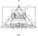
- FIG. 1 illustrates a system 100 for controlling a user interface.
- the system 100 is configured to detect a position of an object touching or hovering above a surface of a display device 105.
- the display device 105 may be, for example, a computer monitor or a television screen.
- the object may be, for example, a user's hand or finger, a stylus or other pointing device, or some other object.
- the system 100 includes a camera 110 configured to capture images of objects positioned in front of the display device 105.
- the camera 110 may be placed at the top of the display 105 and oriented to look down along the surface of the display 105.
- a field-of-view 111 of the camera 110 is a triangular shape, widening downward along the display 105. That is, the camera 110 is positioned such that it may be able to capture images of objects across the entire bottom of the display 105 but may only be able to capture a smaller area of the top of the display 105.
- the field-of-view 111 may be divided into multiple regions 112-116.
- the regions 112-116 each may be defined, for example, as an angle or as a range of angles within the field-of-view 111.
- the regions 112-116 each may be defined as a portion of an image captured by the camera 110. As shown in FIG. 1 , defined regions 112-116 may be of different sizes.
- the system 100 includes LEDs (Light Emitting Diodes) 118-119.
- LEDs Light Emitting Diodes
- illuminating sources other than LEDs may be used.
- the LEDs 118-119 may be positioned to define an active touch region of the field-of-view 111, such that when the LEDs 118-119 are illuminated, only objects positioned in the active touch region are detected.
- An active touch area may be defined, for example, at the bottom of the display device 105.
- the display device 105 may render a display image generated by an application, where the display image includes one or more user input controls.
- Each user input control may be placed, for example, in the active touch area (e.g., an area corresponding to the bottom of the display device 105) and may be associated with a defined region of the field-of-view 111.
- a "BACK" button control 120 is displayed at the bottom of the display device 105 in an area corresponding to region 112
- a "FORWARD" button control 122 is displayed at the bottom of the display device 105 in an area corresponding to region 116.
- a filmstrip control 124 is displayed in an area of the display device 105 corresponding to region 114. The filmstrip control 124 is used to control display of images in an image area 126.
- the camera 110 may capture images of an object (e.g., a user's hand or finger) in front of the display device 105.
- a region 112-116 corresponding to the captured object may be determined.
- An application command may be determined based on the determined region and the determined application command may be executed.
- the finger may be illuminated by the LEDs 118-119 and captured in an image of the camera 110. Based on the detected horizontal position of the user's finger, it may be determined that the finger was captured in region 114. Based on the determined region 114, an image selection command may be determined. The image selection command may be executed and the horizontal position of the finger may be mapped to a particular thumbnail image 128a-d. The mapped thumbnail image (e.g., 128b) may be displayed in a larger size in the image area 126.
- An indicator 130 may indicate which thumbnail 128a-d in the filmstrip 124 is displayed in the image area 126 (e.g., the indicator 130 as shown is positioned above the thumbnail 128b).
- the hand may be illuminated by the LEDs 118-119 and captured by the camera 110 and a corresponding region 112 may be identified.
- a "previous image” command may be determined based on the identified region 112. The previous image command may be executed, resulting in the display of the thumbnail 128a in the image area 126 and in the positioning of the indicator 130 above the thumbnail 128a. Previously unseen images may be revealed in the filmstrip 124 if the user repeatedly touches the "BACK" control button 120.
- the stylus may illuminated and captured in a camera image.
- the region 116 may be determined as a corresponding region and a "next image" command may be determined based on the determined region 116.
- the next image command may be executed, resulting in the display of the thumbnail 128c in the image area 126 and in the positioning of the indicator 130 above the thumbnail 128c.
- Previously unseen images may be revealed in the filmstrip 124 if the user repeatedly touches the "FORWARD" control button 122.
- a gesture made with the object may be detected. For example, a "swiping left”, “swiping right", or “stationary” gesture may be recognized. A gesture may be recognized by comparing motion of the detected object to motion patterns associated with recognized gestures. A recognized gesture may be mapped to an input command. For example, a "swiping left” gesture may be mapped to a "next image” command and a “swiping right” gesture may be mapped to a "previous image” command. A “stationary” gesture may be mapped, for example, to a display menu command.
- a "gesture” is intended to refer to a form of non-verbal communication made with a whole or part of a human body or multiple human bodies, and is contrasted with verbal communication such as speech.
- a gesture may be defined by a movement, change or transformation between a first position, pose, or expression and a second pose, position or expression.
- Example gestures include for instance, an "air quote” gesture, a bowing gesture, a curtsey, a cheek-kiss, a finger or hand motion, a genuflection, a head bobble or movement, a high-five, a nod, a raised fist, a salute, a swiping or wave motion, a thumbs-up motion, or a finger pointing gesture.
- a gesture may be derived that defines an idea, opinion, emotion, communication, command, demonstration or expression of the user.
- the user's gesture may be a single or multiple finger gesture; a single hand gesture; a single hand and arm gesture; a single hand and arm, and body gesture; a bimanual gesture; a change in head pose or posture; a change in a body pose or posture, or a transformation of any other expressive body state.
- control object the body part or parts used to perform relevant gestures are generally referred to as a "control object.”
- the user may express a command using their entire body or with other physical objects, in which case their entire body or the other physical objects may be the control object.
- a user may more subtly express a command by wiggling a finger, in which case the finger may be the control object.
- the user's gesture in a single image or between two images may be expressive of an enabling or "engagement" gesture.
- a control object may also be a physical device, such as an infrared finger light, a retro-reflector, or a remote control.
- a swipe gesture a user may touch the display device 105 and drag the finger towards the left or right in one smooth motion.
- To perform a stationary gesture the user may touch or hover above the display device 105 without moving the finger or hand.
- Gestures may be detected anywhere within the field-of-view 111. In some applications, some or all gestures may not be recognized while interactive button controls are displayed. In some examples, some gestures may be used during the presentation of photographs or videos, so that images can be displayed full screen without overlaying button controls.
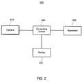
- FIG. 2 illustrates an example of a camera tracker system 200.
- the system 200 includes a camera 210, a display device 220, an illuminator 230, and a computing device 240.
- the system 200 may be included in or used in conjunction with a digital picture frame, a television, a monitor, a product display unit, or any type of media system.
- the camera 210 is a device that captures images.
- the camera 210 may be a digital camera, a digital video camera, or any other type of device that captures images.
- the camera 210 may be a single camera and the system 200 may include only the single camera. In other implementations, multiple cameras may be used.
- the camera 210 may capture images of an object interacting with an interface displayed on the display device 220.
- the camera 210 may capture images of a user or person physically interacting (e.g., with a finger or hand) with an interface displayed on the display device 220.
- the camera 210 may be any type of image sensor and may be a line scan sensor.
- the display device 220 renders a visual display image.
- the display device 220 may be a monitor display, a television display, a liquid crystal display (LCD), a plasma display device, a projector with a projector screen, an auto-stereoscopic display, a cathode ray tube (CRT) display, a digital light processing (DLP) display, a digital picture frame display, or any other type of display device configured to render a visual display image.
- the display device 220 may include one or more display devices.
- the display device 220 may display images associated with an application.
- the display device 220 may render display images generated by an application (e.g., a photo viewing application).
- the display images generated by the application may include an interface with interface controls.
- the system 200 does not include the display device 220.
- the system 200 may be configured to detect objects in front of a different surface, such as a surface of another type of physical object such as a door, elevator, machine, radio, media player, or other object.
- the system 200 is located in front of an area of space, such as a doorway or entryway.
- the illuminator 230 is a device that provides a light source.
- the illuminator 230 may be a flash device, an incandescent light bulb, a fluorescent light bulb, a light emitting diode (LED), a halogen light source, a neon light source, a xenon light source, an infrared light source, or any other type of device configured to illuminate an object being imaged by the camera 210.
- the illuminator 230 may include one or more illuminators.
- the illuminator 230 may generate light to assist in capturing a high quality image of an object being captured by the camera 210. In some implementations, the illuminator 230 may be used in particular situations.
- the illuminator 230 may be used at nighttime or in dark rooms.
- the illuminator 230 may be positioned to define an active touch area within the field of view of the camera 210. Defining active touch areas using the illuminator 230 may increase the accuracy of object detection with a single camera and also may increase the number of control elements that may be detected by a single camera. Using a single camera may help reduce costs of the system and enable gesture-based input control to be realized in less expensive devices.
- the computing device 240 is electrically connected, over a wired or wireless pathway, to the camera 210, the display device 220, and the illuminator 230 and may control operation of the system 200.
- the computing device 240 may include a processor or other control circuitry configured to execute an application.
- the computing device 240 may receive images captured by the camera 210 and process the received images to detect a position of an object (e.g., a user's finger) within the images. The detected position of the object within the images may be tracked and used to control execution of the application.
- the computing device 240 may compare the detected position of the object within the images with regions defined within the camera's field of view. In this example, the computing device 240 may detect that the object is positioned in a particular region, identify an interface control associated with the particular region, and control an application based on a function corresponding to the identified interface control.
- the computing device 240 also may control operation and settings of the camera 210, the display device 220, and the illuminator 230.
- the computing device 240 may be any type of electronic device that includes a processor or other control circuitry configured to execute instructions.
- FIG. 3 is a flow chart illustrating an example of a process 300 for determining user input commands in a camera tracker system.
- FIG. 2 For convenience, particular components described with respect to FIG. 2 are referenced as performing the process 300. However, similar methodologies may be applied in other implementations where different components are used to define the structure of the system, or where the functionality is distributed differently among the components.
- the computing device 240 defines regions in a field of view of the camera 210 (310), and defines an active area in the field of view of the camera 210 using the illuminator 230 (320).
- the computing device 240 may define multiple regions (e.g., an angle within the field of view of the camera 210, a portion of an image captured by the camera 210, etc.) in the field of view of the camera 210 to correspond with interface control elements displayed on the display device 220.
- FIG. 4A illustrates a system 400 which includes a camera 405 placed on top of a display device 410.
- the field-of-view of the camera 405 is divided into regions 411-415.
- the region 411 is shown with a crosshatch pattern.
- User interface controls 421-425 are displayed on the display device 410 and correspond to the regions 411-415, respectively.
- the computing device 240 may define the active touch area in the field of view of the camera 210 by controlling the illuminator 230 to illuminate a portion of the field of view of the camera 210 (e.g., across a surface of the display device 220) that intersects the defined regions (320).
- LED illuminators 430 and 432 illuminate the bottom portion of the display 410, illuminating the bottom portions of regions 411-415.
- the LED illuminators 430 and 432 may be infrared LEDs.
- the computing device 240 renders a display of interface controls on a portion of the display device 220 corresponding to at least a portion of the defined regions in the defined active touch area (330). For example, the computing device 240 may cause the display device 220 to display at least one interface control in each defined region. In this example, the computing device 240 may cause the display device 220 to display the interface controls at a position corresponding to the active touch area defined by the illuminator 230.
- the user interface controls 421-425 are displayed on the display device 410, where each control 421-425 is displayed in a portion of the display device 410 corresponding to a respective region 411-415.
- the user interface controls 421-425 are displayed in the active touch area illuminated by the LEDs 430-432.
- a control shape and size may be chosen so that controls fit within their corresponding region.
- oval-sized controls, such as the button controls 421-425 may generally fit well within triangular regions such as the regions 411-415.
- FIG. 4B illustrates a system 450 which includes rectangular button controls 452-460 each placed, respectively, into a corresponding region 470-475 of a display device 480, where the regions 470-475 divide the field-of-view of a camera 485.
- rectangular buttons may not fit entirely within their own corresponding region.
- the rectangle button 452 does not entirely fit within the region 470, as illustrated by a portion 490 that extends outside of the region 471.
- an overlapping portion 492 indicates that the rectangle button 454 does not fit entirely within the region 472 and extends into the region 471.
- a minimum control width such as one inch, may be used.
- the computing device 240 accesses images captured by the camera 210 (340). For example, the computing device 240 may receive one or more images from the camera 210. The computing device 240 also may access one or images from a storage medium. The computing device 240 may continuously access images of an area proximate to the system 200 or may access images of an area proximate to the system 200 in response to input commands received by the system 200.
- the computing device 240 detects objects in the accessed images (350). For example, the computing device 240 may process or analyze the accessed images to detect a user's finger or another object (e.g., a pointer, a stylus, etc.) in the accessed images. In this example, the computing device 240 may detect a user by comparing features in the accessed images to typical features of objects in images or may detect an object by detecting motion in the accessed images.
- a user's finger or another object e.g., a pointer, a stylus, etc.
- the computing device 240 also may detect a user based on skin color analysis of the accessed images (or detect an object having a known color based on color analysis) or may detect an object by comparing a current image including one or more objects with a background model to detect differences between the current image and the background model.
- the computing device 240 may use any type of technique to detect an object within a single image or within a set of multiple images of the object.
- the computing device 240 ignores objects positioned outside of the defined active touch area (360). For example, the computing device 240 identifies objects illuminated by the illuminator 230 and ignores objects that are not illuminated by the illuminator 230. For example and as shown in FIG. 5 , LEDs 505-510 illuminate the bottom portion of a display device 515, creating an active touch area 520. The active touch area 520 includes the bottom portion of the field-of-view of a camera 525. A top portion of the field-of-view of the camera 525 is not illuminated by the LEDs 505-510, resulting in a false touch area 530. The computing device 240 may identify objects illuminated in the active touch area 520 and may ignore objects in the false touch area 530. The computing device 240 may ignore objects that are within the false touch area 530 by analyzing an image for illuminated objects. Because any objects within the false touch area 530 are not illuminated, the computing device 240 ignores (e.g., does not detect) these objects.
- the computing device 240 detects illuminated objects by comparing pixels of the image captured by the camera to a brightness threshold to produce a binary image. For instance, pixels in the camera image having a brightness value above a threshold may be identified in the binary image with a value of one and pixels having a brightness value below the threshold may be identified in the binary image with a value of zero. In these examples, the computing device 240 analyzes the binary image to detect whether one or more objects are present within the binary image.
- an illumination source is controlled to illuminate in sequence with images captured by the camera in an alternating pattern such that a first image captured by the camera is captured when the illumination source is illuminated and a second image captured by the camera is captured when the illumination source is not illuminated.
- a camera image captured while the illumination source is turned off may be subtracted from a camera image captured while the illumination source was turned on to produce a resulting image.
- the resulting image may be analyzed to determine whether one or more objects are illuminated in the camera image captured when the illumination source was turned on. Subtracting the camera image captured when the illumination source was turned off may remove ambient light which was present in both camera images.
- the computing device 240 determines a defined region that corresponds to a detected object (370). For instance, the computing device 240 compares a position of the detected object in the accessed images to the defined regions within the field of view of the camera 210 and determines in which, if any, of the defined regions the detected object is positioned.
- the computing device 240 determines a command based on the determined region (380).
- the computing device 240 may identify an input command that corresponds to an interface control displayed in the determined region. For example, the computing device 240 may determine to execute a "Play" command when a play input control is displayed on the display device 220 at a position corresponding to determined region. As another example and referring to FIG. 4 , the computing device 240 may determine a command to execute that corresponds to the control 421.
- the computing device 240 may determine a position of the object within the determined region to select a particular command when multiple commands are associated with the determined region.
- a sliding knob input control may be displayed on the display device 220 at a position corresponding to the determined region.
- the sliding knob input control may select a picture to display on the display device 220 from among multiple possible pictures based on a position of the knob in the sliding knob input control.
- the selected picture (or position of the knob in the sliding knob input control) may be determined based on the position of the object within the determined region.
- the sliding knob input control may control a volume of a speaker or may control a zoom setting of a display.
- FIG. 6 illustrates a system 600 which includes a camera 605 placed on top of a display device 610.
- the field-of-view of the camera 605 is divided into regions 612-616.
- a sliding knob input control 620 is displayed at a position in the display device 610 corresponding to the region 614.
- the control 620 includes a "knob" 622.
- the position of the knob 622 may be determined, for example, based on the horizontal position of a user's finger within the region 614.
- An image selected from among a sequence of multiple possible images may be displayed in an image area 630 based on the horizontal position of the knob 622 in the control 620.
- an image which is located at the beginning portion of the sequence of multiple possible images may be selected and displayed in the image area 630.
- an image which is located at the end portion of the sequence of multiple possible images may be selected and displayed in the image area 630.
- the computing device 240 detects a gesture in the determined region and determines a command based on the detected gesture (390).
- the computing device 240 may detect a gesture in the determined region by comparing motion of the detected object within the determined region to motion patterns associated with recognized gestures. When the motion of the detected object matches a motion pattern associated with a recognized gesture, the computing device 240 identifies performance of the recognized gesture and determines a command corresponding to the recognized gesture. For instance, in the example of FIG. 6 , the user may perform a "left swipe" gesture with their finger.
- the computing device 240 may recognize the left swipe gesture and may determine and execute a "next image” command, resulting in the display of a new image in the image area 630, where the new image is next after the currently displayed image in the sequence of multiple possible images.
- the user may perform a "right swipe” gesture with their hand or finger.
- the computing device 240 may recognize the right swipe gesture and may determine and execute a "previous image” command.
- a turning knob control (e.g., a dial) may be displayed in the determined region, and the computing device 240 may determine a command based on a position of the turning knob control (e.g., an amount the turning knob control has been rotated).
- the computing device 240 may detect a user performing a gesture in which the user draws a circle with the detected object within the determined region.
- the computing device 240 may rotate the turning knob control in a direction that is based on whether the user draws the circle in a clockwise direction or a counterclockwise direction, and may determine a command based on the position of the turning knob control after rotation.
- FIG. 7 illustrates a system 700 in which multiple controls are displayed in the same region.
- the system 700 includes a camera 710 placed on top of a display device 720.
- the field-of-view of the camera 710 is divided into multiple regions 722-730.
- An image of an interface for a music player application is displayed on the display device 720.
- the music player application includes button controls 732-740, which are displayed in areas of the display device 720 corresponding to the regions 722-730, respectively.
- the music player application also includes button controls 742-750, which are also displayed in areas of the display device 720 corresponding to the regions 722-730, respectively.
- the button controls 732-750 may be used to control the music player application.
- button 746 is a play button which may be used to play a song currently selected in a play list 755 (an indicator 760 indicates the currently selected song in the play list 755).
- the button controls 742-744 and 748-750 may be used to rewind, pause, stop, and fast forward the currently playing song, respectively.
- Button controls 732-734 may be used to select a different song in the play list 755 by moving the indicator 760 up or down, respectively.
- Button controls 736-738 may be used to decrease or increase the playback volume, respectively.
- Button control 740 may be used, for example, to play the selected song or may be used to display details about the selected song.
- each region 722-730 includes multiple controls.
- region 726 includes both the control 746 and the control 736. If the camera 710 detects a user's finger in the region 726, it may be ambiguous as to which of the control 736 or the control 746 the user intended to select. To avoid this ambiguity, user interfaces may be designed so that each region only includes one control, and additionally, user interfaces may be designed to avoid placing graphics that are visually similar to buttons, scroll bars, or other controls in false touch areas that are not meant to be interactive.
- An approach of using multiple sets of illuminators may be used to support having multiple controls in the same region.
- a first pair of LEDs 770-775 may illuminate the area of the display device 720 corresponding to the button controls 732-740 and a second pair of LEDs 780-785 may illuminate the area of the display device 720 corresponding to the button controls 742-750.
- the LED pairs 770-775 and 780-785 may be illuminated at alternating times, so that the camera 710 captures a first camera image while the LEDs 770-775 are illuminated and captures a second camera image while the LEDs 780-785 are illuminated.
- the computing device 240 may determine whether the user is selecting one of the controls 732-740 or one of the controls 742-750. For example, if an object is detected in the region 724 when the LEDs 780-785 are illuminated, the computing device 240 may identify and execute a pause command associated with the control 744. As another example, if the object is detected in the region 728 when the LEDs 770-775 are illuminated, the computing device 240 may identify and execute an increase volume command associated with the control 738. In some examples, more than two pairs of LEDs may be used, to illuminate more than two areas of the display device 720.
- FIG. 8 illustrates an active touch area for a system 800 which includes multiple pairs of illuminators.
- the system 800 includes LEDs 810-820, which create an active touch area 825 when illuminated.
- the LEDs 810-820 may be illuminated at alternating times with LEDs 830-840, in sequence with images captured by a camera 850.
- the illumination of LEDs 830-840 may create a second active touch area (not shown), which is positioned above the active touch area 825.
- the captured camera images may result in a first set of images in which the LEDs 810-820 are illuminated and the LEDs 830-840 are not illuminated, and in a second set of images in which the LEDs 830-840 are illuminated and the LEDs 810-820 are not illuminated.
- the first set of images may be processed to determine whether an object is detected within the active touch area 825 and the second set of images may be processed to determine whether an object is detected within the second active touch area.
- movement of the detected object may be tracked to determine whether a recognized gesture is performed in the second active touch area.
- FIG. 9 illustrates a system 900 which includes a camera 905 positioned in a corner of a display device 907.
- the camera 905 is positioned in the upper left corner of the display device 907 (e.g., where the left side of the display device 907 meets the top side of the display device 907).
- Using a configuration where the camera 905 is positioned in a corner of the display device 907 may allow for user interface controls to be placed along the two sides opposite the camera 905 (e.g., as shown in FIG. 9 , the camera is placed in the upper left corner of the display device 907 and user interface controls 920-924 are aligned along the right edge of the display device 907 and user interface controls 924-928 are aligned along the bottom edge of the display device 907.
- the user interface controls 920-928 correspond to regions 910-918, respectively.
- the regions 910-918 divide the field-of-view of the camera 905.
- FIG. 10 illustrates a system 1000 which is similar to the system 900 except that rectangular-shaped controls 1001-1009 are used.
- the controls 1001-1009 correspond to regions 1010-1018 which divide a field-of-view of a camera 1020.
- Some of the rectangular-shaped controls 1001-1009 do not fit within the corresponding regions 1010-1018, as illustrated by clipped portions 1022-1028.
- FIG. 11 illustrates a system 1100 which is similar to the system 900 in that a camera 1105 is positioned in the upper left corner of a display device 1107. Regions 1110-1115 divide the field-of-view of the camera 1105.
- a scroll bar control 1121 is located in a region of the display device 1107 corresponding to the region 1110.
- the region 1110 is sized so that it is larger than each of the regions 1111-1115, and is sized to accommodate the height of the scroll bar control 1121.
- the scroll bar control 1121 includes a slider 1122 which may be moved up and down to select a song from a play list 1123.
- An indicator 1124 indicates the currently selected song in the play list 1123.
- Button controls 1131-1135 may be used to fast forward, stop, play, pause, or rewind a song, respectively.
- FIG. 12 illustrates a system 1200 which includes a camera 1205 positioned in the upper left corner of a display device 1210.
- a desired touch area 1220 may be defined at the bottom and right sides of the intersection of the field-of-view of the camera 1205 and the display device 1210.
- the area of the field-of-view of the camera 1205 located above or to the left of the desired touch area 1220 may be defined as a false touch area 1230.
- FIG. 13 illustrates a system 1300 for defining active touch areas.
- the system 1300 includes a camera 1305 positioned at the top left corner of a display device 1307.
- LEDs 1310 and 1315 may be illuminated to define an active touch area 1320.
- Objects in the field-of-view of the camera 1305 in the area of the display device 1307 corresponding to the active touch area 1320 may be recognized, while objects located in the field-of-view of the camera 1305 but outside the active touch area 1320 may be ignored. However, objects may be detected in the center of the display device 1307 (e.g., outside of the active touch area 1320) by illuminating LEDs 1330-1335.
- objects may be detected in the center of the display device 1307 while an application is in a gesture recognition mode.
- a gesture recognition mode camera images may be processed without a segmentation of the field-of-view of the camera 1305 into regions (e.g., a gesture may be recognized regardless of where in the field-of-view the gesture was performed).
- FIG. 14 is a flow chart illustrating an example of a process 1400 for determining user input commands and controlling an application using a camera tracker system.
- FIG. 2 For convenience, particular components described with respect to FIG. 2 are referenced as performing the process 1400. However, similar methodologies may be applied in other implementations where different components are used to define the structure of the system, or where the functionality is distributed differently among the components.
- the computing device 240 accesses an image captured by the camera (1410). For example, the computing device 240 may control the camera 210 to capture one or more images and receive the one or more images from the camera 210. The computing device 240 also may access one or images from a storage medium. The computing device 240 may continuously access images or may access images in response to input commands received by the system 200.
- the computing device 240 determines, from among multiple defined regions within a field of view of the camera, a region in which an object detected within the accessed image is positioned (1420). For example, in reference to FIG. 1 , the computing device 240 may detect an object in an image captured by the camera 110 and determine, from among the regions 112-116, a region in which the object is positioned.
- the computing device 240 detects an object within the accessed image and determines a position of the detected object within the accessed image. Any technique to detect an object within an image and determine a position of the detected object may be used.
- the computing device 240 compares the determined position to the multiple defined regions within the field of view of the camera and, based on comparison results, identifies the region in which the detected object is positioned. For instance, the computing device 240 compares location coordinates of the detected object in the accessed image (e.g., a pixel location) to data defining location coordinates (e.g., pixel locations) of a defined region within the accessed camera image.
- the computing device 240 segments the accessed image into segments that each correspond to one of the multiple defined regions.
- the computing device 240 may, for each of the segments, analyze the segment to determine whether an object is present within the segment.
- the computing device 240 determines that the object is positioned within a particular region that corresponds to the particular segment.
- the segment may be the only portion of the image analyzed to determine whether an object is present within the segment.
- the computing device 240 may determine that an object is present within a segment when the entire object is present within any portion of the segment.
- the computing device 240 determines user input based on the determined region (1430). For instance, an interface control may be displayed at a position corresponding to the determined region. The computing device 240 may map the determined region to the interface control and determine that a user has provided input to activate the interface control.
- a gesture may be detected based on positions of the object detected within a series of images and a user input command may be determined based on the recognized gesture. For example, a "swipe" user input may be detected and a "change station” or “next picture” user input may be determined based on the recognized swipe gesture.
- the computing device 240 controls an application based on the determined user input (1440). For example, the computing device 240 may trigger an operation within the application that corresponds to the determined user input. In this example, when the determined user input is activation of an interface control (e.g., a press of an interface button), the computing device 240 controls the application to perform an operation that is associated with activation of the interface control.
- an interface control e.g., a press of an interface button
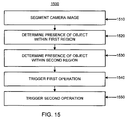
- FIG. 15 is a flow chart illustrating another example of a process 1500 for determining user input commands in a camera tracker system.
- FIG. 2 For convenience, particular components described with respect to FIG. 2 are referenced as performing the process 1500. However, similar methodologies may be applied in other implementations where different components are used to define the structure of the system, or where the functionality is distributed differently among the components.
- the computing device 240 segments an image captured by the camera into a first region that corresponds to a first user interface control and a second region that corresponds to a second user interface control, where the first region of the image is different than the second region of the image (1510).
- the computing device 240 may segment an image captured by the camera 110 into the regions 112-116, where the region 112 corresponds to the control 120 and the region 116 corresponds to the control 122.
- the computing device 240 determines whether an object is present within the first region of the image based on an analysis of the segmented first region of the image (1520). For example, in reference to FIG. 1 , suppose that while the camera image was captured, the user was touching the region 112 of the display device 105. For example, the user's finger may be detected by comparing pixels of the camera image to a brightness threshold to produce a binary image and by clustering pixels within the binary image into one or more blobs. A centroid of a blob may be computed as the position of the corresponding detected object and the detected object position may be compared to positions which define the regions 112-116. In this example, the computing device 240 may determine that an object is present within the region 112.
- the computing device 240 may determine whether an object is present within the first region of the image based on an analysis of only the segmented first region of the image. For instance, in the example of FIG. 1 , the region 112 but not the regions 114-116 might be analyzed. The computing device 240 may determine whether an object is present within any portion of the first region of the image.
- the computing device 240 determines whether an object is present within the second region of the image based on an analysis of the segmented second region of the image (1530). Using the example described above in reference to reference numeral 1520, the computing device 240 may determine that no objects are detected in the region 116.
- the computing device 240 may determine whether an object is present within the second region of the image based on an analysis of only the segmented second region of the image. For instance, in the example of FIG. 1 , the region 116 but not the regions 112-114 might be analyzed. The computing device 240 may determine whether an object is present within any portion of the second region of the image.
- the computing device 240 In response to a determination that an object is present within the first region of the image, the computing device 240 detects activation of the first user interface control and triggers a first operation associated with activation of the first user interface control (1540). For example, in the example above where an object is detected in region 112 of FIG. 1 , the computing device 240 may detect activation of the "BACK" button control 120. A "previous image” command may be determined and executed, resulting in the display of the thumbnail 128a in the image area 126 and in the positioning of the indicator 130 above the thumbnail 128a.
- the computing device 240 may detect activation of the first user interface control in response to a determination that an object is present within the first region of the image regardless of a portion of the first region of the image at which the object is located. For instance, in the example of FIG. 1 , the "BACK" button control may be activated if the object is detected in any location within the region 112.
- the computing device 240 In response to a determination that an object is present within the second region of the image, the computing device 240 detects activation of the second user interface control and triggers a second operation associated with activation of the second user interface control (1550). Suppose that in the example above that an object is detected in region 116 of FIG. 1 instead of in region 112. The computing device 240 may detect activation of the corresponding "FORWARD" button control 122. A "next image" command may be determined and executed, resulting in the display of the thumbnail 128c in the image area 126 and in the positioning of the indicator 130 above the thumbnail 128c.
- FIG. 16 illustrates components of an exemplary computer processing system.
- the system 1600 includes a computing device 1601 that includes a processor configured to control an application that is configured to enable a user to enter text, numbers, or select from a menu of options.
- the device 1601 may be configured to exchange electronic communications over a network 1606 with one or more servers including a server 1602 and a server 1604.
- the hardware environment of the computing device 1601 includes a display monitor 1608 for displaying text and images to a user, a keyboard 1609 for entering text data and user commands into the computing device 1601, a mouse 1610 for pointing, selecting and manipulating objects displayed on the display monitor 1608, a fixed disk drive 1611, a removable disk drive 1612, a tape drive 1614, a hardcopy output device 1615, a computer network connection 1616, and a digital input device 1617.
- the display monitor 1608 displays the graphics, images, and text that comprise the user interface for the software applications used by the computing device 1601, as well as the operating system programs necessary to operate the computing device 1601.
- a user uses the keyboard 1609 to enter commands and data to operate and control the computer operating system programs as well as the application programs.
- the mouse 1610 may be any type of pointing device, and may be a joystick, a trackball, a touch-pad, or other pointing device.
- Software used to display a user interface and enable a user to enter text, numbers, or select from a menu of options is stored locally on computer readable memory media, such as the fixed disk drive 1611.
- the fixed disk drive 1611 itself may include a number of physical drive units, such as a redundant array of independent disks (“RAID”), or may be a disk drive farm or a disk array that is physically located in a separate computing unit.
- RAID redundant array of independent disks
- Such computer readable memory media allow the computing device 1601 to access computer-executable process steps, application programs and the like, stored on removable and non-removable memory media.
- the computer network connection 1616 may be a modem connection, a local-area network (“LAN”) connection including the Ethernet, or a broadband wide-area network (“WAN”) connection such as a digital subscriber line (“DSL”), cable high-speed internet connection, dial-up connection, T-1 line, T-3 line, fiber optic connection, or satellite connection.
- the network 1606 may be a LAN network, a corporate or government WAN network, the Internet, or other network.
- the computer network connection 1616 may be a wireline or wireless connector.
- Example wireless connectors include, for example, an INFRARED DATA ASSOCIATION® (“IrDA®”) wireless connector, an optical wireless connector, an INSTITUTE OF ELECTRICAL AND ELECTRONICS ENGINEERS® (“IEEE®”) Standard 802.11 wireless connector, a BLUETOOTH® wireless connector, an orthogonal frequency division multiplexing (“OFDM”) ultra wide band (“UWB”) wireless connector, a time-modulated ultra wide band (“TM-UWB”) wireless connector, or other wireless connector.
- Example wired connectors include, for example, an IEEE® FIREWIRE® connector, a Universal Serial Bus (“USB”) connector, a serial port connector, a parallel port connector, or other wireline connector.
- the removable disk drive 1612 is a removable storage device that is used to off-load data from the computing device 1601 or upload data onto the computing device 1601.
- the removable disk drive 1612 may be a floppy disk drive, an IOMEGA® ZIF® drive, a compact disk-read only memory (“CD-ROM”) drive, a CD-Recordable drive (“CD-R”), a CD-Rewritable drive (“CD-RW”), flash memory, a USB flash drive, thumb drive, pen drive, key drive, a High-Density Digital Versatile Disc (“HD-DVD”) optical disc drive, a Blu-Ray optical disc drive, a Holographic Digital Data Storage (“HDDS”) optical disc drive, or any one of the various recordable or rewritable digital versatile disc (“DVD”) drives such as the DVD-Recordable (“DVD-R” or “DVD+R”), DVD-Rewritable (“DVD-RW” or “DVD+RW”), or DVD-RAM.
- the tape drive 1614 is a tape storage device that is used to off-load data from the computing device 1601 or to upload data onto the computing device 1601.
- the tape drive 1614 may be a quarter-inch cartridge (“QIC"), 4 mm digital audio tape (“DAT”), 8 mm digital linear tape (“DLT”) drive, or other type of tape.
- the hardcopy output device 1615 provides an output function for the operating system programs and applications.
- the hardcopy output device 1615 may be a printer or any output device that produces tangible output objects, including textual or image data or graphical representations of textual or image data. While the hardcopy output device 1615 is depicted as being directly connected to the computing device 1601, it need not be. For instance, the hardcopy output device may be connected to the computing device 1601 via a network interface, such as a wireline or wireless network.
- the computing device 1601 is described above as a desktop PC, in further implementations the computing device 1601 may be a laptop, a workstation, a midrange computer, a mainframe, an embedded system, telephone, a handheld or tablet computer, a PDA, or other type of computer.
- FIG. 17 is a block diagram illustrating the internal architecture of a computer shown in FIG. 16 .
- the computing environment includes a computer central processing unit (“CPU") 1701, where the computer instructions that comprise an operating system or an application are processed; a display interface 1702 which provides a communication interface and processing functions for rendering graphics, images, and texts on the display monitor 1608; a keyboard interface 1704 which provides a communication interface to the keyboard 1609; a pointing device interface 1705 which provides a communication interface to the mouse 1610 or an equivalent pointing device; a digital input interface 1706 which provides a communication interface to the digital input device 1617; a hardcopy output device interface 1708 which provides a communication interface to the hardcopy output device 1615; a random access memory (“RAM”) 1710 where computer instructions and data are stored in a volatile memory device for processing by the computer CPU 1701; a read-only memory (“ROM”) 1711 where invariant low-level systems code or data for basic system functions such as basic input and output (“ROM”) 1711 where invariant low-level systems
- the RAM 1710 interfaces with the computer bus 1727 so as to provide quick RAM storage to the computer CPU 1701 during the execution of software programs such as the operating system application programs, and device drivers. More specifically, the computer CPU 1701 loads computer-executable process steps from the fixed disk drive 1611 or other memory media into a field of the RAM 1710 in order to execute software programs. Data is stored in the RAM 1710, where the data is accessed by the computer CPU 1701 during execution.
- the computing device 1601 stores computer-executable code for an operating system 1721, application programs 1722 such as word processing, spreadsheet, presentation, gaming, or other applications.
- application programs 1722 such as word processing, spreadsheet, presentation, gaming, or other applications.
- DLL dynamic link library
- plug-in to other application programs
- an Internet web-browser such as the MICROSOFT® Internet Explorer web browser.
- the computer CPU 1701 is one of a number of high-performance computer processors, including an INTEL® or AMD® processor, a POWERPC® processor, a MIPS® reduced instruction set computer ("RISC") processor, a SPARC® processor, an ACORN® RISC Machine (“ARM®”) architecture processor, a HP ALPHASERVER® processor or a proprietary computer processor for a mainframe.
- the computer CPU 1701 is more than one processing unit, including a multiple CPU configuration found in high-performance workstations and servers, or a multiple scalable processing unit found in mainframes.
- the operating system 1721 may be MICROSOFT® WINDOWS NT®/WINDOWS® 2000/WINDOWS® XP Workstation; WINDOWS NT®/WINDOWS® 2000/WINDOWS® XP Server; a variety of UNIX®-flavored operating systems, including AIX® for IBM® workstations and servers, SUNOS® for SUN® workstations and servers, LINUX® for INTEL® CPU-based workstations and servers, HP UX WORKLOAD MANAGER® for HP® workstations and servers, IRIX® for SGI® workstations and servers, VAX/VMS for Digital Equipment Corporation computers, OPENVMS® for HP ALPHASERVER®-based computers, MAC OS® X for POWERPC® based workstations and servers; SYMBIAN OS®, WINDOWS MOBILE® or WINDOWS CE®, PALM®, NOKIA® OS ("NOS”), OSE®, or EPOC® for mobile devices, or a proprietary operating system
- the application development platform or framework for the operating system 1721 may be: BINARY RUNTIME ENVIRONMENT FOR WIRELESS® ("BREW®”); Java Platform, Micro Edition (“Java ME”) or Java 2 Platform, Micro Edition (“J2ME®”); PYTHONTM, FLASH LITE®, or MICROSOFT® .NET Compact.
- FIGS. 16 and 17 illustrate one possible implementation of a computing device that executes program code, or program or process steps, configured to effectuate control of an application that is configured to enable a user to enter text, numbers, or select from a menu of options
- FIGS. 16 and 17 illustrate one possible implementation of a computing device that executes program code, or program or process steps, configured to effectuate control of an application that is configured to enable a user to enter text, numbers, or select from a menu of options
- FIGS. 16 and 17 illustrate one possible implementation of a computing device that executes program code, or program or process steps, configured to effectuate control of an application that is configured to enable a user to enter text, numbers, or select from a menu of options
- other types of computers may also be used as well.
Description
- The present disclosure generally relates to object tracking.
- Cameras have been used to capture images of objects. Techniques have been developed to analyze one or more images of an object present within one or more images to detect a position of the object. For example, optical flow has been used to detect motion of an object by analyzing multiple images of the object taken successively in time.
- In one aspect, an electronic device includes a camera oriented to capture images across a surface and a processing unit configured to perform operations. The operations include accessing an image captured by the camera and identifying multiple regions that are defined within a field of view of the camera and that each correspond to one interface control positioned on the surface. The operations also include determining, from among the multiple defined regions, a region in which an object detected within the accessed image is positioned. The operations further include determining user input based on the one interface control that corresponds to the determined region and controlling an application based on the determined user input.
- Implementations may include one or more of the following features. For example, the operations may include detecting an object within the accessed image and determining a position of the detected object within the accessed image. In this example, the operations also may include comparing the determined position to the multiple defined regions within the field of view of the camera and, based on comparison results, identifying the region in which the detected object is positioned.
- In some implementations, the operations may include segmenting the accessed image into segments that each correspond to one of the multiple defined regions and, for each of the segments, analyzing the segment to determine whether an object is present within the segment. In these implementations, the operations also may include, in response to a determination that an object is present within a particular segment, determining that the object is positioned within a particular region that corresponds to the particular segment. In addition, in these implementations, the operations may include determining that the entire object is present within any portion of the particular region. The segment may be the only portion of the image analyzed to determine whether an object is present within the segment.
- In some examples, the electronic device may include a display screen configured to display a graphical user interface that includes a first user interface control displayed at a first position in the graphical user interface and a second user interface control displayed at a second position in the graphical user interface. The second position in the graphical user interface may be different than the first position in the graphical user interface and the camera is oriented to capture images across a surface of the display screen. In these examples, the operations may include determining whether an object is present within a first region of the image that corresponds to the first user interface control and determining whether an object is present within a second region of the image that corresponds to the second user interface control. Further, in these examples, the operations may include, in response to a determination that an object is present within the first region of the image, detecting activation of the first user interface control and triggering a first operation associated with activation of the first user interface control. The operations also may include, in response to a determination that an object is present within the second region of the image, detecting activation of the second user interface control and triggering a second operation associated with activation of the second user interface control.
- Further, the operations may include controlling the display screen to size and shape the first user interface control to fit within the first region of the image and to size and shape the second user interface control to fit within the second region of the image. The first user interface control may be a first user interface button and the operations may include detecting a press of the first user interface button and triggering a first operation associated with a press of the first user interface button.
- The first user interface control may be a first slider control that spans the first region of the image in a direction that intersects a field of view of the camera and the operations may include detecting engagement of the first slider control in response to a determination that an object is present within the first region of the image. The operations also may include determining a position of the object within the first region of the image along the first slider control and triggering a first operation that is associated with engagement of the first slider control and that uses the determined position of the object within the first region of the image along the first slider control.
- In some implementations, the electronic device may include a light emitting diode oriented to direct light across the surface of the display screen in a direction that intersects the first region of the image and the second region of the image. In these implementations, the light emitting diode may direct light across a part of the first region of the image to define an active area in the part of the first region of the image in which the light from the light emitting diode is directed and a false area in a remainder of the first region of the image in which light from the light emitting diode is absent. The first position in the graphical user interface at which the first user interface control is displayed may correspond to the active area of the first region of the image. The operations may include determining whether an illuminated object is present within the first region of the image to detect objects in the active area of the first region of the image and ignore objects in the false area of the first region of the image.
- In some examples, the light emitting diode is a first light emitting diode configured to illuminate a first area above the display screen and the electronic device includes a second light emitting diode oriented to direct light across the surface of the display screen and configured to illuminate a second area above the display screen that is different than the first area above the display screen illuminated by the first light emitting diode. In these examples, the second area above the display screen illuminated by the second light emitting diode defines a gesture input area and the operations may include detecting gestures within the second area based on an analysis of multiple images captured by the camera.
- In addition, the operations may include controlling the first light emitting diode and the second light emitting diode to illuminate at alternating times in sequence with images captured by the camera. The images captured by the camera may result in a first set of images in which the first light emitting diode is illuminated and the second light emitting diode is not illuminated and a second set of images in which the second light emitting diode is illuminated and the first light emitting diode is not illuminated. The operations may include processing the first set of images in which the first light emitting diode is illuminated and the second light emitting diode is not illuminated to detect activation of the first user interface control and processing the second set of images in which the first light emitting diode is not illuminated and the second light emitting diode is illuminated to detect gestures within the second area.
- In some examples, the operations may include ignoring portions of the image other than the multiple defined regions of the image. In these examples, objects located in portions of the image other than the multiple defined regions of the image are ignored.
- In some implementations, the operations may include detecting performance of a gesture by an object within the region of the image based on an analysis of multiple images captured by the camera, determining a user input command that corresponds to the detected gesture, and triggering a first operation that corresponds to the determined user input command. In these implementations, the operations may include detecting performance of a swiping gesture within the region of the image and a direction of the swiping gesture and determining a user input command that corresponds to the swiping gesture in the determined direction of the swiping gesture.
- In another aspect, at least one computer-readable storage medium encoded with executable instructions that, when executed by at least one processor, cause the at least one processor to perform operations. The operations include accessing an image captured by a camera oriented to capture images across a surface and identifying multiple regions that are defined within a field of view of the camera and that each correspond to one interface control positioned on the surface. The operations also include determining, from among the multiple defined regions, a region in which an object detected within the accessed image is positioned. The operations further include determining user input based on the one interface control that corresponds to the determined region and controlling an application based on the determined user input.
- In yet another aspect, a method includes accessing an image captured by a camera oriented to capture images across a surface and identifying multiple regions that are defined within a field of view of the camera and that each correspond to one interface control positioned on the surface. The method also includes determining, from among the multiple defined regions, a region in which an object detected within the accessed image is positioned. The method further includes determining user input based on the one interface control that corresponds to the determined region and controlling an application based on the determined user input.
- The details of one or more implementations are set forth in the accompanying drawings and the description, below. Other potential features and advantages of the disclosure will be apparent from the description and drawings, and from the claims.
-
-
FIGS. 1, 2, 4A, 4B, 5-13, 16, and 17 illustrate example systems. -
FIGS. 3 ,14 and15 are flowcharts of example processes. - Like reference numbers represent corresponding parts throughout.
- Techniques are described for emulating a two-dimensional interface using a one-dimensional sensor. In some implementations, a system may include a single camera that images a surface of a touch screen interface. In these implementations, the system detects a position of objects in images captured by the single camera in a single dimension (e.g., a horizontal direction when the single camera is placed at the top of the touch screen interface and images downward, such as shown in
FIG. 1 ) and uses the single dimension to control the touch screen interface in two dimensions. Although two sensors (e.g., two cameras) are traditionally needed to provide two-dimensional control, the system is able to control the touch screen interface in two dimensions using the single dimension of the detected object based on intelligent placement of interface elements in the touch screen interface and/or use of illumination sources to define active areas in the touch screen interface. Because, in these implementations, only a single sensor (e.g., a single camera) is needed to provide two-dimensional control, the system may have a lower cost than systems that require two sensors. -
FIG. 1 illustrates asystem 100 for controlling a user interface. Thesystem 100 is configured to detect a position of an object touching or hovering above a surface of adisplay device 105. Thedisplay device 105 may be, for example, a computer monitor or a television screen. The object may be, for example, a user's hand or finger, a stylus or other pointing device, or some other object. - The
system 100 includes acamera 110 configured to capture images of objects positioned in front of thedisplay device 105. Thecamera 110 may be placed at the top of thedisplay 105 and oriented to look down along the surface of thedisplay 105. A field-of-view 111 of thecamera 110 is a triangular shape, widening downward along thedisplay 105. That is, thecamera 110 is positioned such that it may be able to capture images of objects across the entire bottom of thedisplay 105 but may only be able to capture a smaller area of the top of thedisplay 105. The field-of-view 111 may be divided into multiple regions 112-116. The regions 112-116 each may be defined, for example, as an angle or as a range of angles within the field-of-view 111. As another example, the regions 112-116 each may be defined as a portion of an image captured by thecamera 110. As shown inFIG. 1 , defined regions 112-116 may be of different sizes. - The
system 100 includes LEDs (Light Emitting Diodes) 118-119. In some implementations, illuminating sources other than LEDs may be used. The LEDs 118-119 may be positioned to define an active touch region of the field-of-view 111, such that when the LEDs 118-119 are illuminated, only objects positioned in the active touch region are detected. An active touch area may be defined, for example, at the bottom of thedisplay device 105. - The
display device 105 may render a display image generated by an application, where the display image includes one or more user input controls. Each user input control may be placed, for example, in the active touch area (e.g., an area corresponding to the bottom of the display device 105) and may be associated with a defined region of the field-of-view 111. For example, a "BACK"button control 120 is displayed at the bottom of thedisplay device 105 in an area corresponding toregion 112 and a "FORWARD"button control 122 is displayed at the bottom of thedisplay device 105 in an area corresponding toregion 116. Afilmstrip control 124 is displayed in an area of thedisplay device 105 corresponding toregion 114. Thefilmstrip control 124 is used to control display of images in animage area 126. - As the LEDs 118-119 are illuminated, the
camera 110 may capture images of an object (e.g., a user's hand or finger) in front of thedisplay device 105. A region 112-116 corresponding to the captured object may be determined. An application command may be determined based on the determined region and the determined application command may be executed. - For example, if a user points their finger at and touches the
filmstrip control 124, the finger may be illuminated by the LEDs 118-119 and captured in an image of thecamera 110. Based on the detected horizontal position of the user's finger, it may be determined that the finger was captured inregion 114. Based on thedetermined region 114, an image selection command may be determined. The image selection command may be executed and the horizontal position of the finger may be mapped to aparticular thumbnail image 128a-d. The mapped thumbnail image (e.g., 128b) may be displayed in a larger size in theimage area 126. Anindicator 130 may indicate whichthumbnail 128a-d in thefilmstrip 124 is displayed in the image area 126 (e.g., theindicator 130 as shown is positioned above thethumbnail 128b). - As another example, if the user points their hand at and touches the "BACK"
control button 120, the hand may be illuminated by the LEDs 118-119 and captured by thecamera 110 and acorresponding region 112 may be identified. A "previous image" command may be determined based on the identifiedregion 112. The previous image command may be executed, resulting in the display of thethumbnail 128a in theimage area 126 and in the positioning of theindicator 130 above thethumbnail 128a. Previously unseen images may be revealed in thefilmstrip 124 if the user repeatedly touches the "BACK"control button 120. - As yet another example, if the user points a stylus at and touches the "FORWARD"
button control 122, the stylus may illuminated and captured in a camera image. Theregion 116 may be determined as a corresponding region and a "next image" command may be determined based on thedetermined region 116. The next image command may be executed, resulting in the display of thethumbnail 128c in theimage area 126 and in the positioning of theindicator 130 above thethumbnail 128c. Previously unseen images may be revealed in thefilmstrip 124 if the user repeatedly touches the "FORWARD"control button 122. - In addition to simply capturing the presence of an object in front of the
display device 105, a gesture made with the object may be detected. For example, a "swiping left", "swiping right", or "stationary" gesture may be recognized. A gesture may be recognized by comparing motion of the detected object to motion patterns associated with recognized gestures. A recognized gesture may be mapped to an input command. For example, a "swiping left" gesture may be mapped to a "next image" command and a "swiping right" gesture may be mapped to a "previous image" command. A "stationary" gesture may be mapped, for example, to a display menu command. - As used herein throughout, a "gesture" is intended to refer to a form of non-verbal communication made with a whole or part of a human body or multiple human bodies, and is contrasted with verbal communication such as speech. For instance, a gesture may be defined by a movement, change or transformation between a first position, pose, or expression and a second pose, position or expression. Example gestures include for instance, an "air quote" gesture, a bowing gesture, a curtsey, a cheek-kiss, a finger or hand motion, a genuflection, a head bobble or movement, a high-five, a nod, a raised fist, a salute, a swiping or wave motion, a thumbs-up motion, or a finger pointing gesture.
- Accordingly, from a sequence of images, a gesture may be derived that defines an idea, opinion, emotion, communication, command, demonstration or expression of the user. For instance, the user's gesture may be a single or multiple finger gesture; a single hand gesture; a single hand and arm gesture; a single hand and arm, and body gesture; a bimanual gesture; a change in head pose or posture; a change in a body pose or posture, or a transformation of any other expressive body state.
- For brevity, the body part or parts used to perform relevant gestures are generally referred to as a "control object." For instance, the user may express a command using their entire body or with other physical objects, in which case their entire body or the other physical objects may be the control object. A user may more subtly express a command by wiggling a finger, in which case the finger may be the control object. The user's gesture in a single image or between two images may be expressive of an enabling or "engagement" gesture. A control object may also be a physical device, such as an infrared finger light, a retro-reflector, or a remote control.
- While gesturing, the user may graze or hover above the
display device 105. To perform a swipe gesture, a user may touch thedisplay device 105 and drag the finger towards the left or right in one smooth motion. To perform a stationary gesture, the user may touch or hover above thedisplay device 105 without moving the finger or hand. Gestures may be detected anywhere within the field-of-view 111. In some applications, some or all gestures may not be recognized while interactive button controls are displayed. In some examples, some gestures may be used during the presentation of photographs or videos, so that images can be displayed full screen without overlaying button controls. -
FIG. 2 illustrates an example of acamera tracker system 200. Thesystem 200 includes acamera 210, adisplay device 220, anilluminator 230, and acomputing device 240. Thesystem 200 may be included in or used in conjunction with a digital picture frame, a television, a monitor, a product display unit, or any type of media system. - The
camera 210 is a device that captures images. For example, thecamera 210 may be a digital camera, a digital video camera, or any other type of device that captures images. In some implementations, thecamera 210 may be a single camera and thesystem 200 may include only the single camera. In other implementations, multiple cameras may be used. Thecamera 210 may capture images of an object interacting with an interface displayed on thedisplay device 220. For instance, thecamera 210 may capture images of a user or person physically interacting (e.g., with a finger or hand) with an interface displayed on thedisplay device 220. Thecamera 210 may be any type of image sensor and may be a line scan sensor. - The
display device 220 renders a visual display image. For example, thedisplay device 220 may be a monitor display, a television display, a liquid crystal display (LCD), a plasma display device, a projector with a projector screen, an auto-stereoscopic display, a cathode ray tube (CRT) display, a digital light processing (DLP) display, a digital picture frame display, or any other type of display device configured to render a visual display image. Thedisplay device 220 may include one or more display devices. Thedisplay device 220 may display images associated with an application. For instance, thedisplay device 220 may render display images generated by an application (e.g., a photo viewing application). The display images generated by the application may include an interface with interface controls. - In some implementations, the
system 200 does not include thedisplay device 220. For example, thesystem 200 may be configured to detect objects in front of a different surface, such as a surface of another type of physical object such as a door, elevator, machine, radio, media player, or other object. In some examples, thesystem 200 is located in front of an area of space, such as a doorway or entryway. - The
illuminator 230 is a device that provides a light source. For example, theilluminator 230 may be a flash device, an incandescent light bulb, a fluorescent light bulb, a light emitting diode (LED), a halogen light source, a neon light source, a xenon light source, an infrared light source, or any other type of device configured to illuminate an object being imaged by thecamera 210. Theilluminator 230 may include one or more illuminators. Theilluminator 230 may generate light to assist in capturing a high quality image of an object being captured by thecamera 210. In some implementations, theilluminator 230 may be used in particular situations. For instance, theilluminator 230 may be used at nighttime or in dark rooms. Theilluminator 230 may be positioned to define an active touch area within the field of view of thecamera 210. Defining active touch areas using theilluminator 230 may increase the accuracy of object detection with a single camera and also may increase the number of control elements that may be detected by a single camera. Using a single camera may help reduce costs of the system and enable gesture-based input control to be realized in less expensive devices. - The
computing device 240 is electrically connected, over a wired or wireless pathway, to thecamera 210, thedisplay device 220, and theilluminator 230 and may control operation of thesystem 200. In some examples, thecomputing device 240 may include a processor or other control circuitry configured to execute an application. In these examples, thecomputing device 240 may receive images captured by thecamera 210 and process the received images to detect a position of an object (e.g., a user's finger) within the images. The detected position of the object within the images may be tracked and used to control execution of the application. For example, thecomputing device 240 may compare the detected position of the object within the images with regions defined within the camera's field of view. In this example, thecomputing device 240 may detect that the object is positioned in a particular region, identify an interface control associated with the particular region, and control an application based on a function corresponding to the identified interface control. - The
computing device 240 also may control operation and settings of thecamera 210, thedisplay device 220, and theilluminator 230. Thecomputing device 240 may be any type of electronic device that includes a processor or other control circuitry configured to execute instructions. -
FIG. 3 is a flow chart illustrating an example of aprocess 300 for determining user input commands in a camera tracker system. For convenience, particular components described with respect toFIG. 2 are referenced as performing theprocess 300. However, similar methodologies may be applied in other implementations where different components are used to define the structure of the system, or where the functionality is distributed differently among the components. - The
computing device 240 defines regions in a field of view of the camera 210 (310), and defines an active area in the field of view of thecamera 210 using the illuminator 230 (320). Thecomputing device 240 may define multiple regions (e.g., an angle within the field of view of thecamera 210, a portion of an image captured by thecamera 210, etc.) in the field of view of thecamera 210 to correspond with interface control elements displayed on thedisplay device 220. For example,FIG. 4A illustrates asystem 400 which includes acamera 405 placed on top of adisplay device 410. The field-of-view of thecamera 405 is divided into regions 411-415. For example, theregion 411 is shown with a crosshatch pattern. User interface controls 421-425 are displayed on thedisplay device 410 and correspond to the regions 411-415, respectively. - Returning to
FIG. 3 , thecomputing device 240 may define the active touch area in the field of view of thecamera 210 by controlling theilluminator 230 to illuminate a portion of the field of view of the camera 210 (e.g., across a surface of the display device 220) that intersects the defined regions (320). For example and as shown inFIG. 4A ,LED illuminators display 410, illuminating the bottom portions of regions 411-415. TheLED illuminators - Returning to
FIG. 3 , thecomputing device 240 renders a display of interface controls on a portion of thedisplay device 220 corresponding to at least a portion of the defined regions in the defined active touch area (330). For example, thecomputing device 240 may cause thedisplay device 220 to display at least one interface control in each defined region. In this example, thecomputing device 240 may cause thedisplay device 220 to display the interface controls at a position corresponding to the active touch area defined by theilluminator 230. - For example and as shown in
FIG. 4A , the user interface controls 421-425 are displayed on thedisplay device 410, where each control 421-425 is displayed in a portion of thedisplay device 410 corresponding to a respective region 411-415. The user interface controls 421-425 are displayed in the active touch area illuminated by the LEDs 430-432. A control shape and size may be chosen so that controls fit within their corresponding region. For example, oval-sized controls, such as the button controls 421-425, may generally fit well within triangular regions such as the regions 411-415. - Other types of shapes may not fit particularly well within triangle-shaped or other-shaped regions. For example,
FIG. 4B illustrates asystem 450 which includes rectangular button controls 452-460 each placed, respectively, into a corresponding region 470-475 of adisplay device 480, where the regions 470-475 divide the field-of-view of acamera 485. As illustrated inFIG. 4B , rectangular buttons may not fit entirely within their own corresponding region. For example, therectangle button 452 does not entirely fit within theregion 470, as illustrated by aportion 490 that extends outside of the region 471. Similarly, an overlappingportion 492 indicates that therectangle button 454 does not fit entirely within theregion 472 and extends into the region 471. If rectangular buttons are used, they may be spaced apart with sufficient spacing between each button to ensure that each button fits entirely within the corresponding region. A minimum control width, such as one inch, may be used. - Returning to
FIG. 3 , thecomputing device 240 accesses images captured by the camera 210 (340). For example, thecomputing device 240 may receive one or more images from thecamera 210. Thecomputing device 240 also may access one or images from a storage medium. Thecomputing device 240 may continuously access images of an area proximate to thesystem 200 or may access images of an area proximate to thesystem 200 in response to input commands received by thesystem 200. - The
computing device 240 detects objects in the accessed images (350). For example, thecomputing device 240 may process or analyze the accessed images to detect a user's finger or another object (e.g., a pointer, a stylus, etc.) in the accessed images. In this example, thecomputing device 240 may detect a user by comparing features in the accessed images to typical features of objects in images or may detect an object by detecting motion in the accessed images. - The
computing device 240 also may detect a user based on skin color analysis of the accessed images (or detect an object having a known color based on color analysis) or may detect an object by comparing a current image including one or more objects with a background model to detect differences between the current image and the background model. Thecomputing device 240 may use any type of technique to detect an object within a single image or within a set of multiple images of the object. - The
computing device 240 ignores objects positioned outside of the defined active touch area (360). For example, thecomputing device 240 identifies objects illuminated by theilluminator 230 and ignores objects that are not illuminated by theilluminator 230. For example and as shown inFIG. 5 , LEDs 505-510 illuminate the bottom portion of adisplay device 515, creating anactive touch area 520. Theactive touch area 520 includes the bottom portion of the field-of-view of acamera 525. A top portion of the field-of-view of thecamera 525 is not illuminated by the LEDs 505-510, resulting in afalse touch area 530. Thecomputing device 240 may identify objects illuminated in theactive touch area 520 and may ignore objects in thefalse touch area 530. Thecomputing device 240 may ignore objects that are within thefalse touch area 530 by analyzing an image for illuminated objects. Because any objects within thefalse touch area 530 are not illuminated, thecomputing device 240 ignores (e.g., does not detect) these objects. - In some examples, the
computing device 240 detects illuminated objects by comparing pixels of the image captured by the camera to a brightness threshold to produce a binary image. For instance, pixels in the camera image having a brightness value above a threshold may be identified in the binary image with a value of one and pixels having a brightness value below the threshold may be identified in the binary image with a value of zero. In these examples, thecomputing device 240 analyzes the binary image to detect whether one or more objects are present within the binary image. - In some implementations, an illumination source is controlled to illuminate in sequence with images captured by the camera in an alternating pattern such that a first image captured by the camera is captured when the illumination source is illuminated and a second image captured by the camera is captured when the illumination source is not illuminated. In these implementations, a camera image captured while the illumination source is turned off may be subtracted from a camera image captured while the illumination source was turned on to produce a resulting image. The resulting image may be analyzed to determine whether one or more objects are illuminated in the camera image captured when the illumination source was turned on. Subtracting the camera image captured when the illumination source was turned off may remove ambient light which was present in both camera images.
- Returning to
FIG. 3 , for objects in the active touch area, thecomputing device 240 determines a defined region that corresponds to a detected object (370). For instance, thecomputing device 240 compares a position of the detected object in the accessed images to the defined regions within the field of view of thecamera 210 and determines in which, if any, of the defined regions the detected object is positioned. - The
computing device 240 determines a command based on the determined region (380). Thecomputing device 240 may identify an input command that corresponds to an interface control displayed in the determined region. For example, thecomputing device 240 may determine to execute a "Play" command when a play input control is displayed on thedisplay device 220 at a position corresponding to determined region. As another example and referring toFIG. 4 , thecomputing device 240 may determine a command to execute that corresponds to thecontrol 421. - In some implementations, the
computing device 240 may determine a position of the object within the determined region to select a particular command when multiple commands are associated with the determined region. In these implementations, a sliding knob input control may be displayed on thedisplay device 220 at a position corresponding to the determined region. The sliding knob input control may select a picture to display on thedisplay device 220 from among multiple possible pictures based on a position of the knob in the sliding knob input control. The selected picture (or position of the knob in the sliding knob input control) may be determined based on the position of the object within the determined region. In other examples, the sliding knob input control may control a volume of a speaker or may control a zoom setting of a display. - For example,
FIG. 6 illustrates asystem 600 which includes acamera 605 placed on top of adisplay device 610. The field-of-view of thecamera 605 is divided into regions 612-616. A slidingknob input control 620 is displayed at a position in thedisplay device 610 corresponding to theregion 614. Thecontrol 620 includes a "knob" 622. The position of theknob 622 may be determined, for example, based on the horizontal position of a user's finger within theregion 614. An image selected from among a sequence of multiple possible images may be displayed in animage area 630 based on the horizontal position of theknob 622 in thecontrol 620. For example, if the user touches thedisplay device 610 with their finger at a position corresponding to the left portion of theregion 614, an image which is located at the beginning portion of the sequence of multiple possible images may be selected and displayed in theimage area 630. As another example, if the user touches thedisplay device 610 at a position corresponding to the right portion of theregion 614, an image which is located at the end portion of the sequence of multiple possible images may be selected and displayed in theimage area 630. - Returning to
FIG. 3 , thecomputing device 240 detects a gesture in the determined region and determines a command based on the detected gesture (390). Thecomputing device 240 may detect a gesture in the determined region by comparing motion of the detected object within the determined region to motion patterns associated with recognized gestures. When the motion of the detected object matches a motion pattern associated with a recognized gesture, thecomputing device 240 identifies performance of the recognized gesture and determines a command corresponding to the recognized gesture. For instance, in the example ofFIG. 6 , the user may perform a "left swipe" gesture with their finger. Thecomputing device 240 may recognize the left swipe gesture and may determine and execute a "next image" command, resulting in the display of a new image in theimage area 630, where the new image is next after the currently displayed image in the sequence of multiple possible images. As another example, the user may perform a "right swipe" gesture with their hand or finger. Thecomputing device 240 may recognize the right swipe gesture and may determine and execute a "previous image" command. - In some examples, a turning knob control (e.g., a dial) may be displayed in the determined region, and the
computing device 240 may determine a command based on a position of the turning knob control (e.g., an amount the turning knob control has been rotated). In these examples, thecomputing device 240 may detect a user performing a gesture in which the user draws a circle with the detected object within the determined region. Thecomputing device 240 may rotate the turning knob control in a direction that is based on whether the user draws the circle in a clockwise direction or a counterclockwise direction, and may determine a command based on the position of the turning knob control after rotation. -
FIG. 7 illustrates asystem 700 in which multiple controls are displayed in the same region. Thesystem 700 includes acamera 710 placed on top of adisplay device 720. The field-of-view of thecamera 710 is divided into multiple regions 722-730. An image of an interface for a music player application is displayed on thedisplay device 720. The music player application includes button controls 732-740, which are displayed in areas of thedisplay device 720 corresponding to the regions 722-730, respectively. The music player application also includes button controls 742-750, which are also displayed in areas of thedisplay device 720 corresponding to the regions 722-730, respectively. - The button controls 732-750 may be used to control the music player application. For example,
button 746 is a play button which may be used to play a song currently selected in a play list 755 (anindicator 760 indicates the currently selected song in the play list 755). The button controls 742-744 and 748-750 may be used to rewind, pause, stop, and fast forward the currently playing song, respectively. Button controls 732-734 may be used to select a different song in theplay list 755 by moving theindicator 760 up or down, respectively. Button controls 736-738 may be used to decrease or increase the playback volume, respectively.Button control 740 may be used, for example, to play the selected song or may be used to display details about the selected song. - As shown in
FIG. 7 , each region 722-730 includes multiple controls. For example,region 726 includes both thecontrol 746 and thecontrol 736. If thecamera 710 detects a user's finger in theregion 726, it may be ambiguous as to which of thecontrol 736 or thecontrol 746 the user intended to select. To avoid this ambiguity, user interfaces may be designed so that each region only includes one control, and additionally, user interfaces may be designed to avoid placing graphics that are visually similar to buttons, scroll bars, or other controls in false touch areas that are not meant to be interactive. - An approach of using multiple sets of illuminators may be used to support having multiple controls in the same region. For example, a first pair of LEDs 770-775 may illuminate the area of the
display device 720 corresponding to the button controls 732-740 and a second pair of LEDs 780-785 may illuminate the area of thedisplay device 720 corresponding to the button controls 742-750. The LED pairs 770-775 and 780-785 may be illuminated at alternating times, so that thecamera 710 captures a first camera image while the LEDs 770-775 are illuminated and captures a second camera image while the LEDs 780-785 are illuminated. - Depending upon which camera image the object is detected in, the
computing device 240 may determine whether the user is selecting one of the controls 732-740 or one of the controls 742-750. For example, if an object is detected in theregion 724 when the LEDs 780-785 are illuminated, thecomputing device 240 may identify and execute a pause command associated with thecontrol 744. As another example, if the object is detected in theregion 728 when the LEDs 770-775 are illuminated, thecomputing device 240 may identify and execute an increase volume command associated with thecontrol 738. In some examples, more than two pairs of LEDs may be used, to illuminate more than two areas of thedisplay device 720. -
FIG. 8 illustrates an active touch area for asystem 800 which includes multiple pairs of illuminators. Thesystem 800 includes LEDs 810-820, which create anactive touch area 825 when illuminated. The LEDs 810-820 may be illuminated at alternating times with LEDs 830-840, in sequence with images captured by acamera 850. The illumination of LEDs 830-840 may create a second active touch area (not shown), which is positioned above theactive touch area 825. The captured camera images may result in a first set of images in which the LEDs 810-820 are illuminated and the LEDs 830-840 are not illuminated, and in a second set of images in which the LEDs 830-840 are illuminated and the LEDs 810-820 are not illuminated. The first set of images may be processed to determine whether an object is detected within theactive touch area 825 and the second set of images may be processed to determine whether an object is detected within the second active touch area. When an object is detected within the second active touch area, movement of the detected object may be tracked to determine whether a recognized gesture is performed in the second active touch area. -
FIG. 9 illustrates asystem 900 which includes acamera 905 positioned in a corner of adisplay device 907. Thecamera 905 is positioned in the upper left corner of the display device 907 (e.g., where the left side of thedisplay device 907 meets the top side of the display device 907). Using a configuration where thecamera 905 is positioned in a corner of thedisplay device 907 may allow for user interface controls to be placed along the two sides opposite the camera 905 (e.g., as shown inFIG. 9 , the camera is placed in the upper left corner of thedisplay device 907 and user interface controls 920-924 are aligned along the right edge of thedisplay device 907 and user interface controls 924-928 are aligned along the bottom edge of thedisplay device 907. The user interface controls 920-928 correspond to regions 910-918, respectively. The regions 910-918 divide the field-of-view of thecamera 905. - As shown in
FIG. 9 , using oval-shaped interface controls may allow for controls to fit inside of corresponding regions. Other types of control shapes may not generally fit well within corresponding regions when using a camera and region configuration used in thesystem 900. For example,FIG. 10 illustrates asystem 1000 which is similar to thesystem 900 except that rectangular-shaped controls 1001-1009 are used. The controls 1001-1009 correspond to regions 1010-1018 which divide a field-of-view of acamera 1020. Some of the rectangular-shaped controls 1001-1009 do not fit within the corresponding regions 1010-1018, as illustrated by clipped portions 1022-1028. - The configuration of the
system 900 may allow for a vertical scroll bar control. For example,FIG. 11 illustrates asystem 1100 which is similar to thesystem 900 in that acamera 1105 is positioned in the upper left corner of adisplay device 1107. Regions 1110-1115 divide the field-of-view of thecamera 1105. Ascroll bar control 1121 is located in a region of thedisplay device 1107 corresponding to theregion 1110. Theregion 1110 is sized so that it is larger than each of the regions 1111-1115, and is sized to accommodate the height of thescroll bar control 1121. Thescroll bar control 1121 includes aslider 1122 which may be moved up and down to select a song from aplay list 1123. Anindicator 1124 indicates the currently selected song in theplay list 1123. Button controls 1131-1135 may be used to fast forward, stop, play, pause, or rewind a song, respectively. - When using a configuration such as that used in the
system 900 or thesystem 1100, desired touch and false touch areas may be defined. For example,FIG. 12 illustrates asystem 1200 which includes acamera 1205 positioned in the upper left corner of adisplay device 1210. A desiredtouch area 1220 may be defined at the bottom and right sides of the intersection of the field-of-view of thecamera 1205 and thedisplay device 1210. The area of the field-of-view of thecamera 1205 located above or to the left of the desiredtouch area 1220 may be defined as afalse touch area 1230. When designing user interfaces, it may be desirable to place controls in the desiredtouch area 1220 and to avoid placing controls or graphics resembling controls in thefalse touch area 1230. -
FIG. 13 illustrates asystem 1300 for defining active touch areas. Thesystem 1300 includes acamera 1305 positioned at the top left corner of adisplay device 1307.LEDs active touch area 1320. Objects in the field-of-view of thecamera 1305 in the area of thedisplay device 1307 corresponding to theactive touch area 1320 may be recognized, while objects located in the field-of-view of thecamera 1305 but outside theactive touch area 1320 may be ignored. However, objects may be detected in the center of the display device 1307 (e.g., outside of the active touch area 1320) by illuminating LEDs 1330-1335. For example, objects may be detected in the center of thedisplay device 1307 while an application is in a gesture recognition mode. In a gesture recognition mode, camera images may be processed without a segmentation of the field-of-view of thecamera 1305 into regions (e.g., a gesture may be recognized regardless of where in the field-of-view the gesture was performed). -
FIG. 14 is a flow chart illustrating an example of aprocess 1400 for determining user input commands and controlling an application using a camera tracker system. For convenience, particular components described with respect toFIG. 2 are referenced as performing theprocess 1400. However, similar methodologies may be applied in other implementations where different components are used to define the structure of the system, or where the functionality is distributed differently among the components. - The
computing device 240 accesses an image captured by the camera (1410). For example, thecomputing device 240 may control thecamera 210 to capture one or more images and receive the one or more images from thecamera 210. Thecomputing device 240 also may access one or images from a storage medium. Thecomputing device 240 may continuously access images or may access images in response to input commands received by thesystem 200. - The
computing device 240 determines, from among multiple defined regions within a field of view of the camera, a region in which an object detected within the accessed image is positioned (1420). For example, in reference toFIG. 1 , thecomputing device 240 may detect an object in an image captured by thecamera 110 and determine, from among the regions 112-116, a region in which the object is positioned. - In some implementations, the
computing device 240 detects an object within the accessed image and determines a position of the detected object within the accessed image. Any technique to detect an object within an image and determine a position of the detected object may be used. Thecomputing device 240 compares the determined position to the multiple defined regions within the field of view of the camera and, based on comparison results, identifies the region in which the detected object is positioned. For instance, thecomputing device 240 compares location coordinates of the detected object in the accessed image (e.g., a pixel location) to data defining location coordinates (e.g., pixel locations) of a defined region within the accessed camera image. - In some examples, the
computing device 240 segments the accessed image into segments that each correspond to one of the multiple defined regions. In these examples, thecomputing device 240 may, for each of the segments, analyze the segment to determine whether an object is present within the segment. In response to a determination that an object is present within a particular segment, thecomputing device 240 determines that the object is positioned within a particular region that corresponds to the particular segment. In these examples, the segment may be the only portion of the image analyzed to determine whether an object is present within the segment. In addition, thecomputing device 240 may determine that an object is present within a segment when the entire object is present within any portion of the segment. - The
computing device 240 determines user input based on the determined region (1430). For instance, an interface control may be displayed at a position corresponding to the determined region. Thecomputing device 240 may map the determined region to the interface control and determine that a user has provided input to activate the interface control. - In some implementations, a gesture may be detected based on positions of the object detected within a series of images and a user input command may be determined based on the recognized gesture. For example, a "swipe" user input may be detected and a "change station" or "next picture" user input may be determined based on the recognized swipe gesture.
- The
computing device 240 controls an application based on the determined user input (1440). For example, thecomputing device 240 may trigger an operation within the application that corresponds to the determined user input. In this example, when the determined user input is activation of an interface control (e.g., a press of an interface button), thecomputing device 240 controls the application to perform an operation that is associated with activation of the interface control. -
FIG. 15 is a flow chart illustrating another example of aprocess 1500 for determining user input commands in a camera tracker system. For convenience, particular components described with respect toFIG. 2 are referenced as performing theprocess 1500. However, similar methodologies may be applied in other implementations where different components are used to define the structure of the system, or where the functionality is distributed differently among the components. - The
computing device 240 segments an image captured by the camera into a first region that corresponds to a first user interface control and a second region that corresponds to a second user interface control, where the first region of the image is different than the second region of the image (1510). For example, in reference toFIG. 1 , thecomputing device 240 may segment an image captured by thecamera 110 into the regions 112-116, where theregion 112 corresponds to thecontrol 120 and theregion 116 corresponds to thecontrol 122. - The
computing device 240 determines whether an object is present within the first region of the image based on an analysis of the segmented first region of the image (1520). For example, in reference toFIG. 1 , suppose that while the camera image was captured, the user was touching theregion 112 of thedisplay device 105. For example, the user's finger may be detected by comparing pixels of the camera image to a brightness threshold to produce a binary image and by clustering pixels within the binary image into one or more blobs. A centroid of a blob may be computed as the position of the corresponding detected object and the detected object position may be compared to positions which define the regions 112-116. In this example, thecomputing device 240 may determine that an object is present within theregion 112. - The
computing device 240 may determine whether an object is present within the first region of the image based on an analysis of only the segmented first region of the image. For instance, in the example ofFIG. 1 , theregion 112 but not the regions 114-116 might be analyzed. Thecomputing device 240 may determine whether an object is present within any portion of the first region of the image. - The
computing device 240 determines whether an object is present within the second region of the image based on an analysis of the segmented second region of the image (1530). Using the example described above in reference toreference numeral 1520, thecomputing device 240 may determine that no objects are detected in theregion 116. - Similar to the processing for the first image, the
computing device 240 may determine whether an object is present within the second region of the image based on an analysis of only the segmented second region of the image. For instance, in the example ofFIG. 1 , theregion 116 but not the regions 112-114 might be analyzed. Thecomputing device 240 may determine whether an object is present within any portion of the second region of the image. - In response to a determination that an object is present within the first region of the image, the
computing device 240 detects activation of the first user interface control and triggers a first operation associated with activation of the first user interface control (1540). For example, in the example above where an object is detected inregion 112 ofFIG. 1 , thecomputing device 240 may detect activation of the "BACK"button control 120. A "previous image" command may be determined and executed, resulting in the display of thethumbnail 128a in theimage area 126 and in the positioning of theindicator 130 above thethumbnail 128a. - The
computing device 240 may detect activation of the first user interface control in response to a determination that an object is present within the first region of the image regardless of a portion of the first region of the image at which the object is located. For instance, in the example ofFIG. 1 , the "BACK" button control may be activated if the object is detected in any location within theregion 112. - In response to a determination that an object is present within the second region of the image, the
computing device 240 detects activation of the second user interface control and triggers a second operation associated with activation of the second user interface control (1550). Suppose that in the example above that an object is detected inregion 116 ofFIG. 1 instead of inregion 112. Thecomputing device 240 may detect activation of the corresponding "FORWARD"button control 122. A "next image" command may be determined and executed, resulting in the display of thethumbnail 128c in theimage area 126 and in the positioning of theindicator 130 above thethumbnail 128c. -
FIG. 16 illustrates components of an exemplary computer processing system. Briefly, thesystem 1600 includes acomputing device 1601 that includes a processor configured to control an application that is configured to enable a user to enter text, numbers, or select from a menu of options. Thedevice 1601 may be configured to exchange electronic communications over anetwork 1606 with one or more servers including aserver 1602 and aserver 1604. - In more detail, the hardware environment of the
computing device 1601 includes adisplay monitor 1608 for displaying text and images to a user, akeyboard 1609 for entering text data and user commands into thecomputing device 1601, amouse 1610 for pointing, selecting and manipulating objects displayed on thedisplay monitor 1608, afixed disk drive 1611, aremovable disk drive 1612, atape drive 1614, ahardcopy output device 1615, acomputer network connection 1616, and adigital input device 1617. - The
display monitor 1608 displays the graphics, images, and text that comprise the user interface for the software applications used by thecomputing device 1601, as well as the operating system programs necessary to operate thecomputing device 1601. A user uses thekeyboard 1609 to enter commands and data to operate and control the computer operating system programs as well as the application programs. Themouse 1610 may be any type of pointing device, and may be a joystick, a trackball, a touch-pad, or other pointing device. Software used to display a user interface and enable a user to enter text, numbers, or select from a menu of options is stored locally on computer readable memory media, such as the fixeddisk drive 1611. - In a further implementation, the fixed
disk drive 1611 itself may include a number of physical drive units, such as a redundant array of independent disks ("RAID"), or may be a disk drive farm or a disk array that is physically located in a separate computing unit. Such computer readable memory media allow thecomputing device 1601 to access computer-executable process steps, application programs and the like, stored on removable and non-removable memory media. - The
computer network connection 1616 may be a modem connection, a local-area network ("LAN") connection including the Ethernet, or a broadband wide-area network ("WAN") connection such as a digital subscriber line ("DSL"), cable high-speed internet connection, dial-up connection, T-1 line, T-3 line, fiber optic connection, or satellite connection. Thenetwork 1606 may be a LAN network, a corporate or government WAN network, the Internet, or other network. - The
computer network connection 1616 may be a wireline or wireless connector. Example wireless connectors include, for example, an INFRARED DATA ASSOCIATION® ("IrDA®") wireless connector, an optical wireless connector, an INSTITUTE OF ELECTRICAL AND ELECTRONICS ENGINEERS® ("IEEE®") Standard 802.11 wireless connector, a BLUETOOTH® wireless connector, an orthogonal frequency division multiplexing ("OFDM") ultra wide band ("UWB") wireless connector, a time-modulated ultra wide band ("TM-UWB") wireless connector, or other wireless connector. Example wired connectors include, for example, an IEEE® FIREWIRE® connector, a Universal Serial Bus ("USB") connector, a serial port connector, a parallel port connector, or other wireline connector. - The
removable disk drive 1612 is a removable storage device that is used to off-load data from thecomputing device 1601 or upload data onto thecomputing device 1601. Theremovable disk drive 1612 may be a floppy disk drive, an IOMEGA® ZIF® drive, a compact disk-read only memory ("CD-ROM") drive, a CD-Recordable drive ("CD-R"), a CD-Rewritable drive ("CD-RW"), flash memory, a USB flash drive, thumb drive, pen drive, key drive, a High-Density Digital Versatile Disc ("HD-DVD") optical disc drive, a Blu-Ray optical disc drive, a Holographic Digital Data Storage ("HDDS") optical disc drive, or any one of the various recordable or rewritable digital versatile disc ("DVD") drives such as the DVD-Recordable ("DVD-R" or "DVD+R"), DVD-Rewritable ("DVD-RW" or "DVD+RW"), or DVD-RAM. Operating system programs, applications, and various data files, are stored on disks, which are stored on the fixeddisk drive 1611 or on removable media for theremovable disk drive 1612. - The
tape drive 1614 is a tape storage device that is used to off-load data from thecomputing device 1601 or to upload data onto thecomputing device 1601. Thetape drive 1614 may be a quarter-inch cartridge ("QIC"), 4 mm digital audio tape ("DAT"), 8 mm digital linear tape ("DLT") drive, or other type of tape. - The
hardcopy output device 1615 provides an output function for the operating system programs and applications. Thehardcopy output device 1615 may be a printer or any output device that produces tangible output objects, including textual or image data or graphical representations of textual or image data. While thehardcopy output device 1615 is depicted as being directly connected to thecomputing device 1601, it need not be. For instance, the hardcopy output device may be connected to thecomputing device 1601 via a network interface, such as a wireline or wireless network. - Furthermore, although the
computing device 1601 is described above as a desktop PC, in further implementations thecomputing device 1601 may be a laptop, a workstation, a midrange computer, a mainframe, an embedded system, telephone, a handheld or tablet computer, a PDA, or other type of computer. -
FIG. 17 is a block diagram illustrating the internal architecture of a computer shown inFIG. 16 . An exemplary internal architecture of thecomputing device 1601 is now described. The computing environment includes a computer central processing unit ("CPU") 1701, where the computer instructions that comprise an operating system or an application are processed; a display interface 1702 which provides a communication interface and processing functions for rendering graphics, images, and texts on the display monitor 1608; a keyboard interface 1704 which provides a communication interface to the keyboard 1609; a pointing device interface 1705 which provides a communication interface to the mouse 1610 or an equivalent pointing device; a digital input interface 1706 which provides a communication interface to the digital input device 1617; a hardcopy output device interface 1708 which provides a communication interface to the hardcopy output device 1615; a random access memory ("RAM") 1710 where computer instructions and data are stored in a volatile memory device for processing by the computer CPU 1701; a read-only memory ("ROM") 1711 where invariant low-level systems code or data for basic system functions such as basic input and output ("I/O"), startup, or reception of keystrokes from the keyboard 1609 are stored in a non-volatile memory device; and a storage 1720 or other suitable type of memory (e.g., such as random-access memory ("RAM"), read-only memory ("ROM"), programmable read-only memory ("PROM"), erasable programmable read-only memory ("EPROM"), electrically erasable programmable read-only memory ("EEPROM"), magnetic disks, optical disks, floppy disks, hard disks, removable cartridges, flash drives), where the files that comprise an operating system 1721, application programs 1722 (including the user input application 1723, and other applications 1724 as necessary) and data files 1725 are stored; a computer network interface 1716 which provides a communication interface to the network 1606 over the computer network connection 1616. The constituent devices and thecomputer CPU 1701 communicate with each other over thecomputer bus 1727. - The
RAM 1710 interfaces with thecomputer bus 1727 so as to provide quick RAM storage to thecomputer CPU 1701 during the execution of software programs such as the operating system application programs, and device drivers. More specifically, thecomputer CPU 1701 loads computer-executable process steps from the fixeddisk drive 1611 or other memory media into a field of theRAM 1710 in order to execute software programs. Data is stored in theRAM 1710, where the data is accessed by thecomputer CPU 1701 during execution. - The
computing device 1601 stores computer-executable code for anoperating system 1721,application programs 1722 such as word processing, spreadsheet, presentation, gaming, or other applications. Although it is possible to display a user interface and enable a user to enter text, numbers, or select from a menu of options using the above-described implementation, it is also possible to implement the functions according to the present disclosure as a dynamic link library ("DLL"), or as a plug-in to other application programs such as an Internet web-browser such as the MICROSOFT® Internet Explorer web browser. - The
computer CPU 1701 is one of a number of high-performance computer processors, including an INTEL® or AMD® processor, a POWERPC® processor, a MIPS® reduced instruction set computer ("RISC") processor, a SPARC® processor, an ACORN® RISC Machine ("ARM®") architecture processor, a HP ALPHASERVER® processor or a proprietary computer processor for a mainframe. In an additional arrangement, thecomputer CPU 1701 is more than one processing unit, including a multiple CPU configuration found in high-performance workstations and servers, or a multiple scalable processing unit found in mainframes. - The
operating system 1721 may be MICROSOFT® WINDOWS NT®/WINDOWS® 2000/WINDOWS® XP Workstation; WINDOWS NT®/WINDOWS® 2000/WINDOWS® XP Server; a variety of UNIX®-flavored operating systems, including AIX® for IBM® workstations and servers, SUNOS® for SUN® workstations and servers, LINUX® for INTEL® CPU-based workstations and servers, HP UX WORKLOAD MANAGER® for HP® workstations and servers, IRIX® for SGI® workstations and servers, VAX/VMS for Digital Equipment Corporation computers, OPENVMS® for HP ALPHASERVER®-based computers, MAC OS® X for POWERPC® based workstations and servers; SYMBIAN OS®, WINDOWS MOBILE® or WINDOWS CE®, PALM®, NOKIA® OS ("NOS"), OSE®, or EPOC® for mobile devices, or a proprietary operating system for computers or embedded systems. The application development platform or framework for theoperating system 1721 may be: BINARY RUNTIME ENVIRONMENT FOR WIRELESS® ("BREW®"); Java Platform, Micro Edition ("Java ME") orJava 2 Platform, Micro Edition ("J2ME®"); PYTHON™, FLASH LITE®, or MICROSOFT® .NET Compact. - While
FIGS. 16 and17 illustrate one possible implementation of a computing device that executes program code, or program or process steps, configured to effectuate control of an application that is configured to enable a user to enter text, numbers, or select from a menu of options, other types of computers may also be used as well.
Claims (13)
- An electronic device comprising:a camera (110; 210; 405; 485; 525; 605; 710; 850; 905; 1020; 1105; 1205; 1305) positioned at an edge of a surface (105; 220; 410; 480; 515; 610; 720; 907; 1107; 1210; 1307) and oriented to have a field of view (111) to capture images across the surface (105; 220; 410; 480; 515; 610; 720; 907; 1107; 1210; 1307);an illuminator (118, 119; 230; 430, 432; 505, 510; 770, 775; 810, 820; 1310, 1315) positioned to intersect and illuminate a portion of the field of view (111) of the camera (110; 210; 405; 485; 525; 605; 710; 850; 905; 1020; 1105; 1205; 1305) said portion being smaller than the field of view (111) of the camera (110; 210; 405; 485; 525; 605; 710; 850; 905; 1020; 1105; 1205; 1305); anda processing unit (240) configured to perform operations comprising:accessing an image captured by the camera (110; 210; 405; 485; 525; 605; 710; 850; 905; 1020; 1105; 1205; 1305);identifying multiple regions (112-116; 411-415; 470-478; 612-616; 722-730; 910-918; 1010-1018; 1110-1115) within the field of view (111) of the camera (110; 210; 405; 485; 525; 605; 710; 850; 905; 1020; 1105; 1205; 1305) that each correspond to one interface control positioned on the surface (105; 220; 410; 480; 515; 610; 720; 907; 1107; 1210; 1307);defining multiple active touch areas (120-124; 421-425; 452-460; 520; 732-750; 825; 920-928; 1001-1009; 1131-1135; 1220; 1320) as portions within the field of view (111) of the camera (110; 210; 405; 485; 525; 605; 710; 850; 905; 1020; 1105; 1205; 1305) where the illumination by the illuminator (118, 119; 230; 430, 432; 505, 510; 770, 775; 810, 820; 1310, 1315) intersects the multiple identified regions (112-116; 411-415; 470-478; 612-616; 722-730; 910-918; 1010-1018; 1110-1115);determining, from among the multiple active touch areas, an active touch area in which an object detected within the accessed image is positioned;determining user input based on the one interface control that corresponds to the determined active touch area (120-124; 421-425; 452-460; 520; 732-750; 825; 920-928; 1001-1009; 1131-1135; 1220; 1320); andcontrolling an application based on the determined user input.
- The electronic device of claim 1 wherein determining, from among the multiple active touch areas (120-124; 421-425; 452-460; 520; 732-750; 825; 920-928; 1001-1009; 1131-1135; 1220; 1320), an active touch area in which an object detected within the accessed image is positioned comprises:detecting the object within the accessed image;determining a position of the detected object within the accessed image;comparing the determined position to the multiple active touch areas (120-124; 421-425; 452-460; 520; 732-750; 825; 920-928; 1001-1009; 1131-1135; 1220; 1320) within the field of view (111) of the camera (110; 210; 405; 485; 525; 605; 710; 850; 905; 1020; 1105; 1205; 1305); andbased on comparison results, identifying the active touch area (120-124; 421-425; 452-460; 520; 732-750; 825; 920-928; 1001-1009; 1131-1135; 1220; 1320) in which the detected object is positioned.
- The electronic device of claim 1 or 2 wherein determining, from among the multiple active touch areas (120-124; 421-425; 452-460; 520; 732-750; 825; 920-928; 1001-1009; 1131-1135; 1220; 1320), an active touch area (120-124; 421-425; 452-460; 520; 732-750; 825; 920-928; 1001-1009; 1131-1135; 1220; 1320) in which an object detected within the accessed image is positioned comprises:segmenting the accessed image into segments that each correspond to one of the multiple identified regions (112-116; 411-415; 470-478; 612-616; 722-730; 910-918; 1010-1018; 1110-1115);for each of the segments, analyzing the segment to determine whether the object is present within the segment; andin response to a determination that the object is present within a particular segment, determining that the object is positioned within an active touch area (120-124; 421-425; 452-460; 520; 732-750; 825; 920-928; 1001-1009; 1131-1135; 1220; 1320) of a particular region that corresponds to the particular segment.
- The electronic device of any of claims 1 to 3 further comprising a display screen configured to display a graphical user interface that includes a first user interface control displayed at a first position in the graphical user interface corresponding to a first active touch area (120-124; 421-425; 452-460; 520; 732-750; 825; 920-928; 1001-1009; 1131-1135; 1220; 1320) and a second user interface control displayed at a second position in the graphical user interface corresponding to a second active touch area (120-124; 421-425; 452-460; 520; 732-750; 825; 920-928; 1001-1009; 1131-1135; 1220; 1320), the second position in the graphical user interface being different than the first position in the graphical user interface,
wherein the camera (110; 210; 405; 485; 525; 605; 710; 850; 905; 1020; 1105; 1205; 1305) is oriented to capture images across a surface (105; 220; 410; 480; 515; 610; 720; 907; 1107; 1210; 1307) of the display screen,
wherein determining, from among the multiple active touch areas (120-124; 421-425; 452-460; 520; 732-750; 825; 920-928; 1001-1009; 1131-1135; 1220; 1320), an active touch area (120-124; 421-425; 452-460; 520; 732-750; 825; 920-928; 1001-1009; 1131-1135; 1220; 1320) in which an object detected within the accessed image is positioned comprises determining whether the object is present within a first region of the image that corresponds to the first user interface control and determining whether the object is present within a second region of the image that corresponds to the second user interface control, and
wherein determining user input based on the one interface control that corresponds to the determined active touch area (120-124; 421-425; 452-460; 520; 732-750; 825; 920-928; 1001-1009; 1131-1135; 1220; 1320) and controlling an application based on the determined user input comprises:in response to a determination that the object is present within the first active touch area (120-124; 421-425; 452-460; 520; 732-750; 825; 920-928; 1001-1009; 1131-1135; 1220; 1320) of the image, detecting activation of the first user interface control and triggering a first operation associated with activation of the first user interface control; andin response to a determination that an object is present within the second active touch area (120-124; 421-425; 452-460; 520; 732-750; 825; 920-928; 1001-1009; 1131-1135; 1220; 1320) of the image, detecting activation of the second user interface control and triggering a second operation associated with activation of the second user interface control. - The electronic device of claim 4 wherein the processing unit (240) is configured to perform operations further comprising controlling the display screen to size and shape the first user interface control to fit within the first region of the image and to size and shape the second user interface control to fit within the second region of the image.
- The electronic device of claim 4 or 5, wherein the illuminator (118, 119; 230; 430, 432; 505, 510; 770, 775; 810, 820; 1310, 1315) comprises a light emitting diode oriented to direct light across the surface (105; 220; 410; 480; 515; 610; 720; 907; 1107; 1210; 1307) of the display screen in a direction that intersects the first region of the image and the second region of the image.
- The electronic device according to any one of the preceding claims, further comprising a second illuminator (780, 785; 830, 840; 1330, 1335) positioned to illuminate a second portion of the field of view (111) of the camera (110; 210; 405; 485; 525; 605; 710; 850; 905; 1020; 1105; 1205; 1305), the second portion of the field of view (111) of the camera (110; 210; 405; 485; 525; 605; 710; 850; 905; 1020; 1105; 1205; 1305) being different from the portion of the field of view (111) of the camera (110; 210; 405; 485; 525; 605; 710; 850; 905; 1020; 1105; 1205; 1305) illuminated by the first illuminator (118, 119; 230; 430, 432; 505, 510; 770, 775; 810, 820; 1310, 1315).
- The electronic device of claim 7 wherein the second portion of the field of view (111) of the camera (110; 210; 405; 485; 525; 605; 710; 850; 905; 1020; 1105; 1205; 1305) illuminated by the second illuminator (780, 785; 830, 840; 1330, 1335) defines a gesture input area (120-124; 421-425; 452-460; 520; 732-750; 825; 920-928; 1001-1009; 1131-1135; 1220; 1320) and the processing unit (240) is configured to perform operations further comprising detecting gestures within the second area (120-124; 421-425; 452-460; 520; 732-750; 825; 920-928; 1001-1009; 1131-1135; 1220; 1320) based on an analysis of multiple images captured by the camera (110; 210; 405; 485; 525; 605; 710; 850; 905; 1020; 1105; 1205; 1305).
- The electronic device of claim 8 wherein the processing unit (240) is configured to perform operations further comprising:controlling the first illuminator (118, 119; 230; 430, 432; 505, 510; 770, 775; 810, 820; 1310, 1315) and the second illuminator (780, 785; 830, 840; 1330, 1335)to illuminate at alternating times in sequence with images captured by the camera (110; 210; 405; 485; 525; 605; 710; 850; 905; 1020; 1105; 1205; 1305), the images capture by the camera (110; 210; 405; 485; 525; 605; 710; 850; 905; 1020; 1105; 1205; 1305) resulting in a first set of images in which the first illuminator is illuminated and the second illuminator (780, 785; 830, 840; 1330, 1335)is not illuminated and a second set of images in which the second illuminator (780, 785; 830, 840; 1330, 1335)is illuminated and the first illuminator (118, 119; 230; 430, 432; 505, 510; 770, 775; 810, 820; 1310, 1315)is not illuminated;processing the first set of images in which the first illuminator (118, 119; 230; 430, 432; 505, 510; 770, 775; 810, 820; 1310, 1315)is illuminated and the second illuminator (780, 785; 830, 840; 1330, 1335)is not illuminated to detect activation of the first user interface control; and processing the second set of images in which the first illuminator (118, 119; 230; 430, 432; 505, 510; 770, 775; 810, 820; 1310, 1315) is not illuminated and the second illuminator (780, 785; 830, 840; 1330, 1335)is illuminated to detect gestures within the second area (120-124; 421-425; 452-460; 520; 732-750; 825; 920-928; 1001-1009; 1131-1135; 1220; 1320).
- The electronic device of any of the preceding claims:wherein determining, from among the multiple active touch areas (120-124; 421-425; 452-460; 520; 732-750; 825; 920-928; 1001-1009; 1131-1135; 1220; 1320), an active touch area (120-124; 421-425; 452-460; 520; 732-750; 825; 920-928; 1001-1009; 1131-1135; 1220; 1320) in which an object detected within the accessed image is positioned comprises detecting performance of a gesture by an object within the determined active touch area (120-124; 421-425; 452-460; 520; 732-750; 825; 920-928; 1001-1009; 1131-1135; 1220; 1320) of the image based on an analysis of multiple images captured by the camera (110; 210; 405; 485; 525; 605; 710; 850; 905; 1020; 1105; 1205; 1305); andwherein determining user input comprises determining a user input command that corresponds to the detected gesture; andwherein controlling an application based on the determined user input comprises triggering a first operation that corresponds to the determined user input command.
- The electronic device of claim 10:wherein detecting performance of a gesture by an object within the determined active touch area (120-124; 421-425; 452-460; 520; 732-750; 825; 920-928; 1001-1009; 1131-1135; 1220; 1320) of the image based on an analysis of multiple images captured by the camera (110; 210; 405; 485; 525; 605; 710; 850; 905; 1020; 1105; 1205; 1305) comprises detecting performance of a swiping gesture within the determined active touch area (120-124; 421-425; 452-460; 520; 732-750; 825; 920-928; 1001-1009; 1131-1135; 1220; 1320) of the image and a direction of the swiping gesture; andwherein determining a user input command that corresponds to the detected gesture comprises determining a user input command that corresponds to the swiping gesture in the determined direction of the swiping gesture.
- At least one computer-readable storage medium encoded with executable instructions that, when executed by at least one processor, cause the at least one processor to perform operations comprising:accessing an image captured by a camera (110; 210; 405; 485; 525; 605; 710; 850; 905; 1020; 1105; 1205; 1305) positioned at an edge of a surface (105; 220; 410; 480; 515; 610; 720; 907; 1107; 1210; 1307) and oriented to capture images within a field of view (111) across the surface (105; 220; 410; 480; 515; 610; 720; 907; 1107; 1210; 1307), an area smaller than the field of view (111) being illuminated by an illuminator (118, 119; 230; 430, 432; 505, 510; 770, 775; 810, 820; 1310, 1315);identifying multiple regions (112-116; 411-415; 470-478; 612-616; 722-730; 910-918; 1010-1018; 1110-1115) within the field of view (111) of the camera (110; 210; 405; 485; 525; 605; 710; 850; 905; 1020; 1105; 1205; 1305) that each correspond to one interface control positioned on the surface (105; 220; 410; 480; 515; 610; 720; 907; 1107; 1210; 1307);defining multiple active touch areas (120-124; 421-425; 452-460; 520; 732-750; 825; 920-928; 1001-1009; 1131-1135; 1220; 1320) as portions within the field of view (111) of the camera (110; 210; 405; 485; 525; 605; 710; 850; 905; 1020; 1105; 1205; 1305) where the illumination by the illuminator (118, 119; 230; 430, 432; 505, 510; 770, 775; 810, 820; 1310, 1315) intersects the multiple identified regions (112-116; 411-415; 470-478; 612-616; 722-730; 910-918; 1010-1018; 1110-1115);determining, from among the multiple active touch areas (120-124; 421-425; 452-460; 520; 732-750; 825; 920-928; 1001-1009; 1131-1135; 1220; 1320), an active touch area (120-124; 421-425; 452-460; 520; 732-750; 825; 920-928; 1001-1009; 1131-1135; 1220; 1320) in which an object detected within the accessed image is positioned;determining user input based on the one interface control that corresponds to the determined active touch area (120-124; 421-425; 452-460; 520; 732-750; 825; 920-928; 1001-1009; 1131-1135; 1220; 1320); andcontrolling an application based on the determined user input.
- A method comprising:accessing an image captured by a camera (110; 210; 405; 485; 525; 605; 710; 850; 905; 1020; 1105; 1205; 1305) positioned at an edge of a surface (105; 220; 410; 480; 515; 610; 720; 907; 1107; 1210; 1307) and oriented to capture images within a field of view of the camera (111) across the surface (105; 220; 410; 480; 515; 610; 720; 907; 1107; 1210; 1307), a portion of the field of view smaller than the field of view (111) being illuminated by an illuminator positioned to intersect and illuminate said portion (118, 119; 230; 430, 432; 505, 510; 770, 775; 810, 820; 1310, 1315);identifying multiple regions (112-116; 411-415; 470-478; 612-616; 722-730; 910-918; 1010-1018; 1110-1115) within the field of view (111) of the camera (110; 210; 405; 485; 525; 605; 710; 850; 905; 1020; 1105; 1205; 1305) that each correspond to one interface control positioned on the surface (105; 220; 410; 480; 515; 610; 720; 907; 1107; 1210; 1307);defining multiple active touch areas (120-124; 421-425; 452-460; 520; 732-750; 825; 920-928; 1001-1009; 1131-1135; 1220; 1320) as the portions within the field of view (111) of the camera (110; 210; 405; 485; 525; 605; 710; 850; 905; 1020; 1105; 1205; 1305) where the illumination by the illuminator (118, 119; 230; 430, 432; 505, 510; 770, 775; 810, 820; 1310, 1315) intersects the multiple identified regions (112-116; 411-415; 470-478; 612-616; 722-730; 910-918; 1010-1018; 1110-1115);determining, from among the multiple active touch areas (120-124; 421-425; 452-460; 520; 732-750; 825; 920-928; 1001-1009; 1131-1135; 1220; 1320), an active touch area in which an object detected within the accessed image is positioned;determining user input based on the one interface control that corresponds to the determined active touch area (120-124; 421-425; 452-460; 520; 732-750; 825; 920-928; 1001-1009; 1131-1135; 1220; 1320); andcontrolling an application based on the determined user input.
Applications Claiming Priority (2)
| Application Number | Priority Date | Filing Date | Title |
|---|---|---|---|
| US10434008P | 2008-10-10 | 2008-10-10 | |
| PCT/US2009/060548 WO2010042953A1 (en) | 2008-10-10 | 2009-10-13 | Single camera tracker |
Publications (3)
| Publication Number | Publication Date |
|---|---|
| EP2350792A1 EP2350792A1 (en) | 2011-08-03 |
| EP2350792A4 EP2350792A4 (en) | 2014-05-21 |
| EP2350792B1 true EP2350792B1 (en) | 2016-06-22 |
Family
ID=42098488
Family Applications (1)
| Application Number | Title | Priority Date | Filing Date |
|---|---|---|---|
| EP09820054.6A Active EP2350792B1 (en) | 2008-10-10 | 2009-10-13 | Single camera tracker |
Country Status (5)
| Country | Link |
|---|---|
| US (1) | US9030564B2 (en) |
| EP (1) | EP2350792B1 (en) |
| JP (1) | JP5529146B2 (en) |
| CN (1) | CN103392163B (en) |
| WO (1) | WO2010042953A1 (en) |
Families Citing this family (56)
| Publication number | Priority date | Publication date | Assignee | Title |
|---|---|---|---|---|
| US9586135B1 (en) | 2008-11-12 | 2017-03-07 | David G. Capper | Video motion capture for wireless gaming |
| US10086262B1 (en) | 2008-11-12 | 2018-10-02 | David G. Capper | Video motion capture for wireless gaming |
| US9383814B1 (en) | 2008-11-12 | 2016-07-05 | David G. Capper | Plug and play wireless video game |
| JP5567908B2 (en) * | 2009-06-24 | 2014-08-06 | キヤノン株式会社 | Three-dimensional measuring apparatus, measuring method and program |
| US8457353B2 (en) * | 2010-05-18 | 2013-06-04 | Microsoft Corporation | Gestures and gesture modifiers for manipulating a user-interface |
| US20110307842A1 (en) * | 2010-06-14 | 2011-12-15 | I-Jen Chiang | Electronic reading device |
| EP2583152A4 (en) * | 2010-06-17 | 2016-08-17 | Nokia Technologies Oy | Method and apparatus for determining input |
| JP2012058921A (en) * | 2010-09-07 | 2012-03-22 | Sony Corp | Information processor, information processing method and program |
| JP5653206B2 (en) * | 2010-12-27 | 2015-01-14 | 日立マクセル株式会社 | Video processing device |
| US8928589B2 (en) * | 2011-04-20 | 2015-01-06 | Qualcomm Incorporated | Virtual keyboards and methods of providing the same |
| US8957967B2 (en) * | 2011-06-03 | 2015-02-17 | Honeywell International Inc. | System and method to control surveillance cameras via three dimensional metaphor and cursor |
| US9727132B2 (en) * | 2011-07-01 | 2017-08-08 | Microsoft Technology Licensing, Llc | Multi-visor: managing applications in augmented reality environments |
| JP5799627B2 (en) * | 2011-07-15 | 2015-10-28 | セイコーエプソン株式会社 | Position detection apparatus, position detection system, and display system with input function |
| US8988394B2 (en) * | 2011-10-25 | 2015-03-24 | Semiconductor Components Industries, Llc | Electronic devices with camera-based user interfaces |
| JP2013105346A (en) * | 2011-11-14 | 2013-05-30 | Sony Corp | Information presentation device, information presentation method, information presentation system, information registration device, information registration method, information registration system, and program |
| US8719734B2 (en) | 2011-11-16 | 2014-05-06 | Microsoft Corporation | Two-stage swipe gesture recognition |
| WO2013094778A1 (en) * | 2011-12-19 | 2013-06-27 | Empire Technology Development Llc | Pause and resume schemes for gesture-based game |
| US11493998B2 (en) | 2012-01-17 | 2022-11-08 | Ultrahaptics IP Two Limited | Systems and methods for machine control |
| US20150253428A1 (en) | 2013-03-15 | 2015-09-10 | Leap Motion, Inc. | Determining positional information for an object in space |
| US8693731B2 (en) | 2012-01-17 | 2014-04-08 | Leap Motion, Inc. | Enhanced contrast for object detection and characterization by optical imaging |
| US9679215B2 (en) | 2012-01-17 | 2017-06-13 | Leap Motion, Inc. | Systems and methods for machine control |
| US9501152B2 (en) | 2013-01-15 | 2016-11-22 | Leap Motion, Inc. | Free-space user interface and control using virtual constructs |
| US8638989B2 (en) | 2012-01-17 | 2014-01-28 | Leap Motion, Inc. | Systems and methods for capturing motion in three-dimensional space |
| US10691219B2 (en) | 2012-01-17 | 2020-06-23 | Ultrahaptics IP Two Limited | Systems and methods for machine control |
| US9747306B2 (en) * | 2012-05-25 | 2017-08-29 | Atheer, Inc. | Method and apparatus for identifying input features for later recognition |
| US9158389B1 (en) * | 2012-10-15 | 2015-10-13 | Tangible Play, Inc. | Virtualization of tangible interface objects |
| US10657694B2 (en) | 2012-10-15 | 2020-05-19 | Tangible Play, Inc. | Activity surface detection, display and enhancement of a virtual scene |
| US10033943B1 (en) | 2012-10-15 | 2018-07-24 | Tangible Play, Inc. | Activity surface detection, display and enhancement |
| US9459697B2 (en) | 2013-01-15 | 2016-10-04 | Leap Motion, Inc. | Dynamic, free-space user interactions for machine control |
| JP6155689B2 (en) * | 2013-02-22 | 2017-07-05 | 株式会社ニコン | Authentication apparatus and authentication method |
| US9916009B2 (en) | 2013-04-26 | 2018-03-13 | Leap Motion, Inc. | Non-tactile interface systems and methods |
| US10281987B1 (en) | 2013-08-09 | 2019-05-07 | Leap Motion, Inc. | Systems and methods of free-space gestural interaction |
| CN105473482A (en) | 2013-08-15 | 2016-04-06 | 奥的斯电梯公司 | Sensors for conveyance control |
| US9721383B1 (en) | 2013-08-29 | 2017-08-01 | Leap Motion, Inc. | Predictive information for free space gesture control and communication |
| US9632572B2 (en) | 2013-10-03 | 2017-04-25 | Leap Motion, Inc. | Enhanced field of view to augment three-dimensional (3D) sensory space for free-space gesture interpretation |
| US9996638B1 (en) | 2013-10-31 | 2018-06-12 | Leap Motion, Inc. | Predictive information for free space gesture control and communication |
| WO2015084227A1 (en) * | 2013-12-06 | 2015-06-11 | Telefonaktiebolaget L M Ericsson (Publ) | Optical head mounted display, television portal module and methods for controlling graphical user interface |
| JP6355081B2 (en) * | 2014-03-10 | 2018-07-11 | 任天堂株式会社 | Information processing device |
| DE202014103729U1 (en) | 2014-08-08 | 2014-09-09 | Leap Motion, Inc. | Augmented reality with motion detection |
| TWI531954B (en) | 2014-11-14 | 2016-05-01 | 中強光電股份有限公司 | Touch and gesture control system and touch and gesture control method |
| CN107402654B (en) * | 2016-05-18 | 2021-07-16 | 原相科技股份有限公司 | Touch detection method and touch detection system |
| USD811486S1 (en) | 2016-05-24 | 2018-02-27 | Tangible Play, Inc. | Programming tile |
| USD795348S1 (en) | 2016-05-24 | 2017-08-22 | Tangible Play, Inc. | Programming tile |
| USD795349S1 (en) | 2016-05-24 | 2017-08-22 | Tangible Play, Inc. | Programming tile |
| USD811485S1 (en) | 2016-05-24 | 2018-02-27 | Tangible Play, Inc. | Programming tile |
| USD871419S1 (en) | 2016-05-24 | 2019-12-31 | Tangible Play, Inc. | Display screen or portion thereof with a graphical user interface |
| USD812143S1 (en) | 2016-05-24 | 2018-03-06 | Tangible Play, Inc. | Programming tile |
| USD837239S1 (en) | 2016-07-06 | 2019-01-01 | Fujifilm Corporation | Digital camera display panel with transitional graphical user interface |
| CN107091800A (en) * | 2017-06-06 | 2017-08-25 | 深圳小孚医疗科技有限公司 | Focusing system and focus method for micro-imaging particle analysis |
| EP3659013B1 (en) * | 2017-07-27 | 2022-03-09 | Alcon Inc. | Controlling a laser surgical device with a sensation generator and a gesture detector |
| GB2591902B (en) | 2018-09-17 | 2022-06-08 | Tangible Play Inc | Display positioning system |
| US10380440B1 (en) | 2018-10-23 | 2019-08-13 | Capital One Services, Llc | Method for determining correct scanning distance using augmented reality and machine learning models |
| JP2019053769A (en) * | 2018-12-04 | 2019-04-04 | シャープ株式会社 | Touch detection apparatus, touch detection system, touch detection method, and program |
| USD907032S1 (en) | 2019-07-07 | 2021-01-05 | Tangible Play, Inc. | Virtualization device |
| US20210006730A1 (en) | 2019-07-07 | 2021-01-07 | Tangible Play, Inc. | Computing device |
| KR20220028951A (en) | 2020-08-31 | 2022-03-08 | 삼성전자주식회사 | Electronic apparatus and controlling method thereof |
Family Cites Families (22)
| Publication number | Priority date | Publication date | Assignee | Title |
|---|---|---|---|---|
| JP3462889B2 (en) | 1993-04-22 | 2003-11-05 | シャープ株式会社 | Optical touch panel and driving method thereof |
| US6973202B2 (en) * | 1998-10-23 | 2005-12-06 | Varian Medical Systems Technologies, Inc. | Single-camera tracking of an object |
| KR20030072591A (en) | 2001-01-08 | 2003-09-15 | 브이케이비 인코포레이티드 | A data input device |
| JP3080041U (en) | 2001-03-06 | 2001-09-14 | 株式会社アシストコンピュータシステムズ | Input device |
| JP2002312123A (en) | 2001-04-16 | 2002-10-25 | Hitachi Eng Co Ltd | Touch position detecting device |
| US7830362B2 (en) * | 2001-07-05 | 2010-11-09 | Michael Cain Finley | Laser and digital camera computer pointer device system |
| US7710391B2 (en) * | 2002-05-28 | 2010-05-04 | Matthew Bell | Processing an image utilizing a spatially varying pattern |
| US7134080B2 (en) * | 2002-08-23 | 2006-11-07 | International Business Machines Corporation | Method and system for a user-following interface |
| US7358963B2 (en) * | 2002-09-09 | 2008-04-15 | Apple Inc. | Mouse having an optically-based scrolling feature |
| US7665041B2 (en) * | 2003-03-25 | 2010-02-16 | Microsoft Corporation | Architecture for controlling a computer using hand gestures |
| JP2005135329A (en) | 2003-10-31 | 2005-05-26 | Calsonic Kansei Corp | Optical touch panel |
| EP3693889A3 (en) * | 2005-01-07 | 2020-10-28 | QUALCOMM Incorporated | Detecting and tracking objects in images |
| CN101536494B (en) * | 2005-02-08 | 2017-04-26 | 奥布隆工业有限公司 | System and method for genture based control system |
| US20060267927A1 (en) * | 2005-05-27 | 2006-11-30 | Crenshaw James E | User interface controller method and apparatus for a handheld electronic device |
| KR100936689B1 (en) * | 2005-06-30 | 2010-01-13 | 가부시키가이샤 리코 | Projection image display device |
| US8154599B2 (en) * | 2005-07-29 | 2012-04-10 | Panasonic Corporation | Imaging region adjustment device |
| US20070165007A1 (en) * | 2006-01-13 | 2007-07-19 | Gerald Morrison | Interactive input system |
| JP2008186374A (en) | 2007-01-31 | 2008-08-14 | Seiko Instruments Inc | Optical touch panel |
| EP2153377A4 (en) * | 2007-05-04 | 2017-05-31 | Qualcomm Incorporated | Camera-based user input for compact devices |
| US7835999B2 (en) * | 2007-06-27 | 2010-11-16 | Microsoft Corporation | Recognizing input gestures using a multi-touch input device, calculated graphs, and a neural network with link weights |
| US8400407B2 (en) * | 2007-07-18 | 2013-03-19 | Smart Technologies Ulc | Touch panel and interactive input system incorporating the same |
| JP4636149B2 (en) * | 2008-09-09 | 2011-02-23 | ソニー株式会社 | Image data analysis apparatus, image data analysis method, and program |
-
2009
- 2009-10-13 US US12/578,505 patent/US9030564B2/en active Active
- 2009-10-13 WO PCT/US2009/060548 patent/WO2010042953A1/en active Application Filing
- 2009-10-13 EP EP09820054.6A patent/EP2350792B1/en active Active
- 2009-10-13 JP JP2011531259A patent/JP5529146B2/en not_active Expired - Fee Related
- 2009-10-13 CN CN200980147735.4A patent/CN103392163B/en active Active
Also Published As
| Publication number | Publication date |
|---|---|
| JP2012505615A (en) | 2012-03-01 |
| WO2010042953A1 (en) | 2010-04-15 |
| US9030564B2 (en) | 2015-05-12 |
| CN103392163B (en) | 2016-10-26 |
| CN103392163A (en) | 2013-11-13 |
| EP2350792A4 (en) | 2014-05-21 |
| EP2350792A1 (en) | 2011-08-03 |
| JP5529146B2 (en) | 2014-06-25 |
| US20100091110A1 (en) | 2010-04-15 |
Similar Documents
| Publication | Publication Date | Title |
|---|---|---|
| EP2350792B1 (en) | Single camera tracker | |
| US8897496B2 (en) | Hover detection | |
| US9746934B2 (en) | Navigation approaches for multi-dimensional input | |
| US10001838B2 (en) | Feature tracking for device input | |
| US7880720B2 (en) | Gesture recognition method and touch system incorporating the same | |
| Agarwal et al. | High precision multi-touch sensing on surfaces using overhead cameras | |
| US9772689B2 (en) | Enhanced gesture-based image manipulation | |
| US20130194173A1 (en) | Touch free control of electronic systems and associated methods | |
| US20090208057A1 (en) | Virtual controller for visual displays | |
| US20090103780A1 (en) | Hand-Gesture Recognition Method | |
| US9317171B2 (en) | Systems and methods for implementing and using gesture based user interface widgets with camera input | |
| CA2830491C (en) | Manipulating graphical objects in a multi-touch interactive system | |
| US9411432B2 (en) | Systems and methods for enabling gesture control based on detection of occlusion patterns | |
| JP2004246578A (en) | Interface method and device using self-image display, and program | |
| WO2012094740A1 (en) | Method for supporting multiple menus and interactive input system employing same | |
| US20150242179A1 (en) | Augmented peripheral content using mobile device | |
| CA2885950A1 (en) | Interactive input system and method for grouping graphical objects | |
| US20220137712A1 (en) | Information processing apparatus, information processing method, and program |
Legal Events
| Date | Code | Title | Description |
|---|---|---|---|
| PUAI | Public reference made under article 153(3) epc to a published international application that has entered the european phase |
Free format text: ORIGINAL CODE: 0009012 |
|
| 17P | Request for examination filed |
Effective date: 20110510 |
|
| AK | Designated contracting states |
Kind code of ref document: A1 Designated state(s): AT BE BG CH CY CZ DE DK EE ES FI FR GB GR HR HU IE IS IT LI LT LU LV MC MK MT NL NO PL PT RO SE SI SK SM TR |
|
| RAP1 | Party data changed (applicant data changed or rights of an application transferred) |
Owner name: QUALCOMM INCORPORATED |
|
| DAX | Request for extension of the european patent (deleted) | ||
| A4 | Supplementary search report drawn up and despatched |
Effective date: 20140417 |
|
| RIC1 | Information provided on ipc code assigned before grant |
Ipc: G06F 3/042 20060101AFI20140411BHEP Ipc: G06K 9/00 20060101ALI20140411BHEP Ipc: G06F 3/01 20060101ALI20140411BHEP |
|
| 17Q | First examination report despatched |
Effective date: 20140513 |
|
| GRAP | Despatch of communication of intention to grant a patent |
Free format text: ORIGINAL CODE: EPIDOSNIGR1 |
|
| INTG | Intention to grant announced |
Effective date: 20160115 |
|
| GRAS | Grant fee paid |
Free format text: ORIGINAL CODE: EPIDOSNIGR3 |
|
| GRAA | (expected) grant |
Free format text: ORIGINAL CODE: 0009210 |
|
| AK | Designated contracting states |
Kind code of ref document: B1 Designated state(s): AT BE BG CH CY CZ DE DK EE ES FI FR GB GR HR HU IE IS IT LI LT LU LV MC MK MT NL NO PL PT RO SE SI SK SM TR |
|
| REG | Reference to a national code |
Ref country code: GB Ref legal event code: FG4D |
|
| REG | Reference to a national code |
Ref country code: CH Ref legal event code: EP |
|
| REG | Reference to a national code |
Ref country code: IE Ref legal event code: FG4D |
|
| REG | Reference to a national code |
Ref country code: AT Ref legal event code: REF Ref document number: 808026 Country of ref document: AT Kind code of ref document: T Effective date: 20160715 |
|
| REG | Reference to a national code |
Ref country code: DE Ref legal event code: R096 Ref document number: 602009039383 Country of ref document: DE |
|
| REG | Reference to a national code |
Ref country code: LT Ref legal event code: MG4D |
|
| REG | Reference to a national code |
Ref country code: NL Ref legal event code: MP Effective date: 20160622 |
|
| PG25 | Lapsed in a contracting state [announced via postgrant information from national office to epo] |
Ref country code: NO Free format text: LAPSE BECAUSE OF FAILURE TO SUBMIT A TRANSLATION OF THE DESCRIPTION OR TO PAY THE FEE WITHIN THE PRESCRIBED TIME-LIMIT Effective date: 20160922 Ref country code: FI Free format text: LAPSE BECAUSE OF FAILURE TO SUBMIT A TRANSLATION OF THE DESCRIPTION OR TO PAY THE FEE WITHIN THE PRESCRIBED TIME-LIMIT Effective date: 20160622 Ref country code: LT Free format text: LAPSE BECAUSE OF FAILURE TO SUBMIT A TRANSLATION OF THE DESCRIPTION OR TO PAY THE FEE WITHIN THE PRESCRIBED TIME-LIMIT Effective date: 20160622 |
|
| REG | Reference to a national code |
Ref country code: AT Ref legal event code: MK05 Ref document number: 808026 Country of ref document: AT Kind code of ref document: T Effective date: 20160622 |
|
| PG25 | Lapsed in a contracting state [announced via postgrant information from national office to epo] |
Ref country code: HR Free format text: LAPSE BECAUSE OF FAILURE TO SUBMIT A TRANSLATION OF THE DESCRIPTION OR TO PAY THE FEE WITHIN THE PRESCRIBED TIME-LIMIT Effective date: 20160622 Ref country code: NL Free format text: LAPSE BECAUSE OF FAILURE TO SUBMIT A TRANSLATION OF THE DESCRIPTION OR TO PAY THE FEE WITHIN THE PRESCRIBED TIME-LIMIT Effective date: 20160622 Ref country code: GR Free format text: LAPSE BECAUSE OF FAILURE TO SUBMIT A TRANSLATION OF THE DESCRIPTION OR TO PAY THE FEE WITHIN THE PRESCRIBED TIME-LIMIT Effective date: 20160923 Ref country code: SE Free format text: LAPSE BECAUSE OF FAILURE TO SUBMIT A TRANSLATION OF THE DESCRIPTION OR TO PAY THE FEE WITHIN THE PRESCRIBED TIME-LIMIT Effective date: 20160622 Ref country code: LV Free format text: LAPSE BECAUSE OF FAILURE TO SUBMIT A TRANSLATION OF THE DESCRIPTION OR TO PAY THE FEE WITHIN THE PRESCRIBED TIME-LIMIT Effective date: 20160622 |
|
| PG25 | Lapsed in a contracting state [announced via postgrant information from national office to epo] |
Ref country code: SK Free format text: LAPSE BECAUSE OF FAILURE TO SUBMIT A TRANSLATION OF THE DESCRIPTION OR TO PAY THE FEE WITHIN THE PRESCRIBED TIME-LIMIT Effective date: 20160622 Ref country code: RO Free format text: LAPSE BECAUSE OF FAILURE TO SUBMIT A TRANSLATION OF THE DESCRIPTION OR TO PAY THE FEE WITHIN THE PRESCRIBED TIME-LIMIT Effective date: 20160622 Ref country code: IT Free format text: LAPSE BECAUSE OF FAILURE TO SUBMIT A TRANSLATION OF THE DESCRIPTION OR TO PAY THE FEE WITHIN THE PRESCRIBED TIME-LIMIT Effective date: 20160622 Ref country code: EE Free format text: LAPSE BECAUSE OF FAILURE TO SUBMIT A TRANSLATION OF THE DESCRIPTION OR TO PAY THE FEE WITHIN THE PRESCRIBED TIME-LIMIT Effective date: 20160622 Ref country code: CZ Free format text: LAPSE BECAUSE OF FAILURE TO SUBMIT A TRANSLATION OF THE DESCRIPTION OR TO PAY THE FEE WITHIN THE PRESCRIBED TIME-LIMIT Effective date: 20160622 Ref country code: IS Free format text: LAPSE BECAUSE OF FAILURE TO SUBMIT A TRANSLATION OF THE DESCRIPTION OR TO PAY THE FEE WITHIN THE PRESCRIBED TIME-LIMIT Effective date: 20161022 |
|
| PG25 | Lapsed in a contracting state [announced via postgrant information from national office to epo] |
Ref country code: AT Free format text: LAPSE BECAUSE OF FAILURE TO SUBMIT A TRANSLATION OF THE DESCRIPTION OR TO PAY THE FEE WITHIN THE PRESCRIBED TIME-LIMIT Effective date: 20160622 Ref country code: ES Free format text: LAPSE BECAUSE OF FAILURE TO SUBMIT A TRANSLATION OF THE DESCRIPTION OR TO PAY THE FEE WITHIN THE PRESCRIBED TIME-LIMIT Effective date: 20160622 Ref country code: PL Free format text: LAPSE BECAUSE OF FAILURE TO SUBMIT A TRANSLATION OF THE DESCRIPTION OR TO PAY THE FEE WITHIN THE PRESCRIBED TIME-LIMIT Effective date: 20160622 Ref country code: PT Free format text: LAPSE BECAUSE OF FAILURE TO SUBMIT A TRANSLATION OF THE DESCRIPTION OR TO PAY THE FEE WITHIN THE PRESCRIBED TIME-LIMIT Effective date: 20161024 Ref country code: BE Free format text: LAPSE BECAUSE OF NON-PAYMENT OF DUE FEES Effective date: 20160622 Ref country code: SM Free format text: LAPSE BECAUSE OF FAILURE TO SUBMIT A TRANSLATION OF THE DESCRIPTION OR TO PAY THE FEE WITHIN THE PRESCRIBED TIME-LIMIT Effective date: 20160622 |
|
| REG | Reference to a national code |
Ref country code: DE Ref legal event code: R097 Ref document number: 602009039383 Country of ref document: DE |
|
| PLBE | No opposition filed within time limit |
Free format text: ORIGINAL CODE: 0009261 |
|
| STAA | Information on the status of an ep patent application or granted ep patent |
Free format text: STATUS: NO OPPOSITION FILED WITHIN TIME LIMIT |
|
| 26N | No opposition filed |
Effective date: 20170323 |
|
| PG25 | Lapsed in a contracting state [announced via postgrant information from national office to epo] |
Ref country code: DK Free format text: LAPSE BECAUSE OF FAILURE TO SUBMIT A TRANSLATION OF THE DESCRIPTION OR TO PAY THE FEE WITHIN THE PRESCRIBED TIME-LIMIT Effective date: 20160622 |
|
| REG | Reference to a national code |
Ref country code: CH Ref legal event code: PL |
|
| REG | Reference to a national code |
Ref country code: IE Ref legal event code: MM4A |
|
| REG | Reference to a national code |
Ref country code: FR Ref legal event code: ST Effective date: 20170630 |
|
| PG25 | Lapsed in a contracting state [announced via postgrant information from national office to epo] |
Ref country code: LI Free format text: LAPSE BECAUSE OF NON-PAYMENT OF DUE FEES Effective date: 20161031 Ref country code: CH Free format text: LAPSE BECAUSE OF NON-PAYMENT OF DUE FEES Effective date: 20161031 Ref country code: FR Free format text: LAPSE BECAUSE OF NON-PAYMENT OF DUE FEES Effective date: 20161102 |
|
| PG25 | Lapsed in a contracting state [announced via postgrant information from national office to epo] |
Ref country code: LU Free format text: LAPSE BECAUSE OF NON-PAYMENT OF DUE FEES Effective date: 20161013 Ref country code: SI Free format text: LAPSE BECAUSE OF FAILURE TO SUBMIT A TRANSLATION OF THE DESCRIPTION OR TO PAY THE FEE WITHIN THE PRESCRIBED TIME-LIMIT Effective date: 20160622 |
|
| PG25 | Lapsed in a contracting state [announced via postgrant information from national office to epo] |
Ref country code: IE Free format text: LAPSE BECAUSE OF NON-PAYMENT OF DUE FEES Effective date: 20161013 |
|
| PG25 | Lapsed in a contracting state [announced via postgrant information from national office to epo] |
Ref country code: HU Free format text: LAPSE BECAUSE OF FAILURE TO SUBMIT A TRANSLATION OF THE DESCRIPTION OR TO PAY THE FEE WITHIN THE PRESCRIBED TIME-LIMIT; INVALID AB INITIO Effective date: 20091013 Ref country code: CY Free format text: LAPSE BECAUSE OF FAILURE TO SUBMIT A TRANSLATION OF THE DESCRIPTION OR TO PAY THE FEE WITHIN THE PRESCRIBED TIME-LIMIT Effective date: 20160622 |
|
| PG25 | Lapsed in a contracting state [announced via postgrant information from national office to epo] |
Ref country code: MC Free format text: LAPSE BECAUSE OF FAILURE TO SUBMIT A TRANSLATION OF THE DESCRIPTION OR TO PAY THE FEE WITHIN THE PRESCRIBED TIME-LIMIT Effective date: 20160622 Ref country code: TR Free format text: LAPSE BECAUSE OF FAILURE TO SUBMIT A TRANSLATION OF THE DESCRIPTION OR TO PAY THE FEE WITHIN THE PRESCRIBED TIME-LIMIT Effective date: 20160622 Ref country code: MT Free format text: LAPSE BECAUSE OF NON-PAYMENT OF DUE FEES Effective date: 20161031 Ref country code: MK Free format text: LAPSE BECAUSE OF FAILURE TO SUBMIT A TRANSLATION OF THE DESCRIPTION OR TO PAY THE FEE WITHIN THE PRESCRIBED TIME-LIMIT Effective date: 20160622 |
|
| PG25 | Lapsed in a contracting state [announced via postgrant information from national office to epo] |
Ref country code: BG Free format text: LAPSE BECAUSE OF FAILURE TO SUBMIT A TRANSLATION OF THE DESCRIPTION OR TO PAY THE FEE WITHIN THE PRESCRIBED TIME-LIMIT Effective date: 20160622 |
|
| PGFP | Annual fee paid to national office [announced via postgrant information from national office to epo] |
Ref country code: GB Payment date: 20230914 Year of fee payment: 15 |
|
| PGFP | Annual fee paid to national office [announced via postgrant information from national office to epo] |
Ref country code: DE Payment date: 20230915 Year of fee payment: 15 |