EP2350577B1 - Magnet device and vibration-type measuring sensor having such a magnet device - Google Patents
Magnet device and vibration-type measuring sensor having such a magnet device Download PDFInfo
- Publication number
- EP2350577B1 EP2350577B1 EP09748315.0A EP09748315A EP2350577B1 EP 2350577 B1 EP2350577 B1 EP 2350577B1 EP 09748315 A EP09748315 A EP 09748315A EP 2350577 B1 EP2350577 B1 EP 2350577B1
- Authority
- EP
- European Patent Office
- Prior art keywords
- magnetic
- retaining
- permanent magnet
- cup
- measuring tube
- Prior art date
- Legal status (The legal status is an assumption and is not a legal conclusion. Google has not performed a legal analysis and makes no representation as to the accuracy of the status listed.)
- Active
Links
- 230000005291 magnetic effect Effects 0.000 claims description 110
- 239000000463 material Substances 0.000 claims description 12
- 230000005520 electrodynamics Effects 0.000 claims description 8
- 229910000679 solder Inorganic materials 0.000 claims description 8
- 229910000831 Steel Inorganic materials 0.000 claims description 7
- 239000010959 steel Substances 0.000 claims description 7
- 239000000853 adhesive Substances 0.000 claims description 5
- 230000001070 adhesive effect Effects 0.000 claims description 5
- 238000013461 design Methods 0.000 claims description 5
- 229910000859 α-Fe Inorganic materials 0.000 claims description 5
- 239000003795 chemical substances by application Substances 0.000 claims description 4
- 230000003993 interaction Effects 0.000 claims description 4
- 229910001172 neodymium magnet Inorganic materials 0.000 claims description 4
- 229910000938 samarium–cobalt magnet Inorganic materials 0.000 claims description 4
- 229910000828 alnico Inorganic materials 0.000 claims description 3
- 229910052761 rare earth metal Inorganic materials 0.000 claims description 3
- 150000002910 rare earth metals Chemical class 0.000 claims description 3
- -1 NdFeB Chemical class 0.000 claims description 2
- 230000015572 biosynthetic process Effects 0.000 claims description 2
- 229910000746 Structural steel Inorganic materials 0.000 claims 1
- 238000003754 machining Methods 0.000 claims 1
- 238000000034 method Methods 0.000 description 16
- 230000008569 process Effects 0.000 description 15
- 230000008878 coupling Effects 0.000 description 12
- 238000010168 coupling process Methods 0.000 description 12
- 238000005859 coupling reaction Methods 0.000 description 12
- 230000005284 excitation Effects 0.000 description 11
- 230000010355 oscillation Effects 0.000 description 11
- 238000005452 bending Methods 0.000 description 10
- 230000001419 dependent effect Effects 0.000 description 8
- 238000011156 evaluation Methods 0.000 description 7
- 238000003825 pressing Methods 0.000 description 5
- 238000006243 chemical reaction Methods 0.000 description 4
- 230000001105 regulatory effect Effects 0.000 description 4
- RTAQQCXQSZGOHL-UHFFFAOYSA-N Titanium Chemical compound [Ti] RTAQQCXQSZGOHL-UHFFFAOYSA-N 0.000 description 3
- 230000008901 benefit Effects 0.000 description 3
- 238000004519 manufacturing process Methods 0.000 description 3
- 238000012544 monitoring process Methods 0.000 description 3
- 238000005476 soldering Methods 0.000 description 3
- 229910052719 titanium Inorganic materials 0.000 description 3
- 239000010936 titanium Substances 0.000 description 3
- 238000003466 welding Methods 0.000 description 3
- 229910000915 Free machining steel Inorganic materials 0.000 description 2
- 229910001209 Low-carbon steel Inorganic materials 0.000 description 2
- QCWXUUIWCKQGHC-UHFFFAOYSA-N Zirconium Chemical compound [Zr] QCWXUUIWCKQGHC-UHFFFAOYSA-N 0.000 description 2
- 230000001133 acceleration Effects 0.000 description 2
- 230000009471 action Effects 0.000 description 2
- 238000004026 adhesive bonding Methods 0.000 description 2
- 238000005219 brazing Methods 0.000 description 2
- 239000000919 ceramic Substances 0.000 description 2
- 230000000295 complement effect Effects 0.000 description 2
- 230000001143 conditioned effect Effects 0.000 description 2
- 239000004020 conductor Substances 0.000 description 2
- 230000000694 effects Effects 0.000 description 2
- 229910052751 metal Inorganic materials 0.000 description 2
- 239000002184 metal Substances 0.000 description 2
- 229910001092 metal group alloy Inorganic materials 0.000 description 2
- 238000012545 processing Methods 0.000 description 2
- 239000011265 semifinished product Substances 0.000 description 2
- 230000001953 sensory effect Effects 0.000 description 2
- 229910052715 tantalum Inorganic materials 0.000 description 2
- GUVRBAGPIYLISA-UHFFFAOYSA-N tantalum atom Chemical compound [Ta] GUVRBAGPIYLISA-UHFFFAOYSA-N 0.000 description 2
- 229910052726 zirconium Inorganic materials 0.000 description 2
- QJVKUMXDEUEQLH-UHFFFAOYSA-N [B].[Fe].[Nd] Chemical compound [B].[Fe].[Nd] QJVKUMXDEUEQLH-UHFFFAOYSA-N 0.000 description 1
- 230000002457 bidirectional effect Effects 0.000 description 1
- KPLQYGBQNPPQGA-UHFFFAOYSA-N cobalt samarium Chemical compound [Co].[Sm] KPLQYGBQNPPQGA-UHFFFAOYSA-N 0.000 description 1
- 238000004891 communication Methods 0.000 description 1
- 238000010276 construction Methods 0.000 description 1
- 238000001514 detection method Methods 0.000 description 1
- 238000007598 dipping method Methods 0.000 description 1
- 238000010292 electrical insulation Methods 0.000 description 1
- 239000004744 fabric Substances 0.000 description 1
- 239000003302 ferromagnetic material Substances 0.000 description 1
- 239000007789 gas Substances 0.000 description 1
- 230000005484 gravity Effects 0.000 description 1
- 229910000856 hastalloy Inorganic materials 0.000 description 1
- 238000000265 homogenisation Methods 0.000 description 1
- 238000009434 installation Methods 0.000 description 1
- 239000007788 liquid Substances 0.000 description 1
- 238000005259 measurement Methods 0.000 description 1
- 238000010327 methods by industry Methods 0.000 description 1
- 230000003534 oscillatory effect Effects 0.000 description 1
- 230000002093 peripheral effect Effects 0.000 description 1
- 230000001681 protective effect Effects 0.000 description 1
- 238000005096 rolling process Methods 0.000 description 1
- 230000003068 static effect Effects 0.000 description 1
Images


Classifications
-
- G—PHYSICS
- G01—MEASURING; TESTING
- G01F—MEASURING VOLUME, VOLUME FLOW, MASS FLOW OR LIQUID LEVEL; METERING BY VOLUME
- G01F1/00—Measuring the volume flow or mass flow of fluid or fluent solid material wherein the fluid passes through a meter in a continuous flow
- G01F1/76—Devices for measuring mass flow of a fluid or a fluent solid material
- G01F1/78—Direct mass flowmeters
- G01F1/80—Direct mass flowmeters operating by measuring pressure, force, momentum, or frequency of a fluid flow to which a rotational movement has been imparted
- G01F1/84—Coriolis or gyroscopic mass flowmeters
- G01F1/845—Coriolis or gyroscopic mass flowmeters arrangements of measuring means, e.g., of measuring conduits
- G01F1/8468—Coriolis or gyroscopic mass flowmeters arrangements of measuring means, e.g., of measuring conduits vibrating measuring conduits
- G01F1/849—Coriolis or gyroscopic mass flowmeters arrangements of measuring means, e.g., of measuring conduits vibrating measuring conduits having straight measuring conduits
-
- G—PHYSICS
- G01—MEASURING; TESTING
- G01F—MEASURING VOLUME, VOLUME FLOW, MASS FLOW OR LIQUID LEVEL; METERING BY VOLUME
- G01F1/00—Measuring the volume flow or mass flow of fluid or fluent solid material wherein the fluid passes through a meter in a continuous flow
- G01F1/76—Devices for measuring mass flow of a fluid or a fluent solid material
- G01F1/78—Direct mass flowmeters
- G01F1/80—Direct mass flowmeters operating by measuring pressure, force, momentum, or frequency of a fluid flow to which a rotational movement has been imparted
- G01F1/84—Coriolis or gyroscopic mass flowmeters
- G01F1/8409—Coriolis or gyroscopic mass flowmeters constructional details
- G01F1/8413—Coriolis or gyroscopic mass flowmeters constructional details means for influencing the flowmeter's motional or vibrational behaviour, e.g., conduit support or fixing means, or conduit attachments
- G01F1/8418—Coriolis or gyroscopic mass flowmeters constructional details means for influencing the flowmeter's motional or vibrational behaviour, e.g., conduit support or fixing means, or conduit attachments motion or vibration balancing means
-
- G—PHYSICS
- G01—MEASURING; TESTING
- G01F—MEASURING VOLUME, VOLUME FLOW, MASS FLOW OR LIQUID LEVEL; METERING BY VOLUME
- G01F1/00—Measuring the volume flow or mass flow of fluid or fluent solid material wherein the fluid passes through a meter in a continuous flow
- G01F1/76—Devices for measuring mass flow of a fluid or a fluent solid material
- G01F1/78—Direct mass flowmeters
- G01F1/80—Direct mass flowmeters operating by measuring pressure, force, momentum, or frequency of a fluid flow to which a rotational movement has been imparted
- G01F1/84—Coriolis or gyroscopic mass flowmeters
- G01F1/8409—Coriolis or gyroscopic mass flowmeters constructional details
- G01F1/8427—Coriolis or gyroscopic mass flowmeters constructional details detectors
-
- G—PHYSICS
- G01—MEASURING; TESTING
- G01N—INVESTIGATING OR ANALYSING MATERIALS BY DETERMINING THEIR CHEMICAL OR PHYSICAL PROPERTIES
- G01N11/00—Investigating flow properties of materials, e.g. viscosity, plasticity; Analysing materials by determining flow properties
- G01N11/10—Investigating flow properties of materials, e.g. viscosity, plasticity; Analysing materials by determining flow properties by moving a body within the material
- G01N11/16—Investigating flow properties of materials, e.g. viscosity, plasticity; Analysing materials by determining flow properties by moving a body within the material by measuring damping effect upon oscillatory body
-
- G—PHYSICS
- G01—MEASURING; TESTING
- G01N—INVESTIGATING OR ANALYSING MATERIALS BY DETERMINING THEIR CHEMICAL OR PHYSICAL PROPERTIES
- G01N9/00—Investigating density or specific gravity of materials; Analysing materials by determining density or specific gravity
- G01N9/002—Investigating density or specific gravity of materials; Analysing materials by determining density or specific gravity using variation of the resonant frequency of an element vibrating in contact with the material submitted to analysis
Definitions
- the invention relates to a, in particular for a vibration transducer and / or for a transducer of the vibration type suitable, magnetic device with a magnetic field-supplying permanent magnet, a permanently connected to the permanent magnet holding device and a magnetic cup. Moreover, the invention relates to a vibration-type transducer equipped with at least one such magnetic device for a medium flowing in a pipeline.
- Such - often formed by means of an in-line meter in a compact design with integrated transducer, such as a Coriolis mass flow meter - measuring systems have long been known and have proven themselves in industrial use.
- Examples of such measuring systems with a transducer of the vibration type or individual components thereof are, for example in the WO-A 88/02475 , the WO-A 88/03642 .
- Each of the transducers shown therein comprises at least one substantially straight or at least one curved measuring tube for guiding the medium to be measured, possibly also extremely cold or extremely hot. Furthermore, everyone in the US-A 52 91 792 , the US-A 59 45 609 , the US-B 70 77 014 , the US-A 2007/0119264 , the WO-A 01 02 816 or even the WO-A 99/40 394 shown transducer, esp.
- the measuring tube with counter-oscillator coupled thereto and the proposed excitation and sensor arrangement enclosing additional converter housing is formed quasi by the counteroscillator itself or, in other words, transducer housing and counteroscillator one and the same unit.
- the at least one measuring tube is vibrated in operation for the purpose of generating through the medium flowing through with influenced waveforms.
- vibration-type transducers further comprise an electrical drive signal generated during operation by a driver signal generated by the mentioned driver electronics and suitably conditioned, eg a regulated current and / or a regulated voltage.
- This excites the measuring tube by means of at least one electromechanical, esp.
- Electro-dynamic, vibration exciter in the useful mode by means of at least one during operation of an excitation current.
- sensors include a sensor array with, esp.
- Electro-dynamic, vibration sensors for at least selectively detecting inlet-side and Auslenfiner oscillations of the at least one measuring tube, esp. Those in Coriolis mode, and for generating of the process parameters to be detected, such as the mass flow or the density , affected electrical sensor signals.
- the transducer as, inter alia, in the EP-A 831 306 , the US-A 57 36 653 , the US-A 53 81 697 or the WO-A 01/02 816 proposed, even more, esp.
- the detection of rather secondary quantities such as temperature, acceleration, strain, tension, etc., serving at least by means of measuring tube, counteroscillator and the respective exciter and sensor assembly formed inside part or arranged in the vicinity Have sensors.
- the so-called Nutzmode - is usually in measuring transducers with curved, for example U-, V- or ⁇ -like shaped, measuring tube Selected natural vibration mode in which the measuring tube oscillates at least partially at a lowest natural resonant frequency about an imaginary longitudinal axis of the transducer in the manner of a clamped at one end cantilever, whereby in the medium flowing through mass-dependent Coriolis forces are induced.
- these Coriolis force-induced cantilever oscillations in Coriolis mode usually correspond to those natural vibration modes in which the measuring tube also executes torsional vibrations about an imaginary vertical axis oriented perpendicular to the longitudinal axis.
- such a useful mode is often selected for generating mass flow-dependent Coriolis forces in which the measuring tube carries out bending vibrations substantially in a single imaginary plane of vibration, so that the oscillations in the Coriolis mode are correspondingly designed as bending oscillations of the same oscillation frequency that are coplanar with the useful mode oscillations are.
- the means of the sensor arrangement on the inlet side and outlet side detected vibrations of the vibrating measuring tube on a dependent on the mass flow, measurable phase difference.
- the measuring tubes of such, for example, used in Coriolis mass flow meters transducers during operation at a momentary natural resonant frequency of the selected mode for the mode of vibration, esp. At constant-controlled oscillation amplitude, excited. Since this resonant frequency is particularly dependent on the instantaneous density of the medium, in addition to the mass flow rate, the density of flowing media can also be measured by means of commercially available Coriolis mass flow meters.
- each of the sensors shown comprises, with a single measuring tube, in each case at least one integral or multi-part, for example tubular, box-shaped or plate-shaped, Counteroscillator, which is coupled to form a first coupling zone inlet side to the measuring tube and the outlet side coupled to form a second coupling zone to the measuring tube, and which rests in operation substantially or the measuring tube gegentechnisch, ie the same frequency and out of phase, oscillates.
- the formed by means of measuring tube and counteroscillator inner part of the transducer is usually alone by means of two connecting pipe pieces, which communicates the measuring tube in operation with the process line, mounted in a protective Meßaufsacrificing housing, esp. In a vibration of the inner part relative to the measuring tube enabling manner.
- transducers with a single, substantially straight measuring tube are the latter and the counteroscillator, as quite common in conventional sensors, each other substantially coaxially aligned.
- the counteroscillator substantially tubular and formed as a substantially straight hollow cylinder which is arranged in the transducer so that the measuring tube is at least partially encased by the counteroscillator.
- materials for such counteroscillators esp. When using titanium, tantalum or zirconium for the measuring tube, usually relatively inexpensive steel grades, such as mild steel or free-cutting steel used.
- the exciter array of transducers of the type in question usually has at least one on the at least one measuring tube and the counter-oscillator or the possibly existing other measuring tube usually differentially acting, vibration exciter serving, usually electrodynamic, magnetic device, while the sensor arrangement as einlenfiner Including vibration sensor on the inlet side, usually also electrodynamic, magnetic device and at least one substantially identical, serving as Auslenfiner vibration sensor outlet side magnetic device comprises.
- vibration exciter serving usually electrodynamic, magnetic device
- the sensor arrangement as einlledgemanent, magnetic device usually also electrodynamic, magnetic device and at least one substantially identical, serving as Auslledgewooder vibration sensor outlet side magnetic device comprises.
- at least serving as a vibration sensor magnetic device are substantially identical.
- Such as vibration transducer serving magnetic devices marketable transducers of the vibration type are by means of a - in transducers with a measuring tube and a counter-oscillator coupled thereto usually fixed to the latter - magnetic coil and interacting with the at least one magnetic coil, esp. In this dipping, serving as an anchor rather elongated, esp. Bar-shaped, permanent magnets formed, which is fixed according to the measuring tube to be moved.
- This has the advantage, for example, that by means of the magnetic devices, the oscillatory movements between the vibrating measuring tube and its counterpart, that is to say the optionally present counteroscillator or the optionally present other measuring tube, can be detected or generated differentially.
- the permanent magnet and serving as exciter or sensor coil magnetic coil are usually aligned so that they are substantially coaxial with each other.
- conventional transducers serving as vibration exciter magnet means is usually designed and placed in the transducer that it acts substantially centrally of the at least one measuring tube.
- the serving as a vibration exciter magnetic devices such as in the in the US Pat. No. 5,796,010 , the US-B 68 40 109 , the US-B 70 77 014 or the US-B 70 17 424 Shown proposed transducers, usually at least selectively fixed along an imaginary central peripheral line of the measuring tube outside of this.
- transducers of the type in question is, as, inter alia, in the US-A 60 47 457 or the US-B 69 20 798 mentioned, also common magnetic coil and the corresponding permanent magnet of the vibration transducer - it is now a vibration exciter or a vibration sensor - serving magnetic device to be applied to the measuring tube ring- or annular disc-shaped, esp. Metallic, fasteners to support the measuring tube in each case substantially along one of its imaginary circumference span tightly.
- the respective fastener may, inter alia, in the US-A 60 47 457 .
- the magnetic devices serving as vibration sensors are often substantially identical, at least insofar as the at least one magnetic device serving as vibration exciter, as they operate on the same operating principle.
- the magnetic devices of such a sensor arrangement are usually each by means of at least one - usually at the existing counter-oscillator - at least temporarily interspersed by a variable magnetic field and concomitantly at least temporarily acted upon by an induced measuring voltage and fixed to the measuring tube, with the at least a magnetic coil co-operating rod-shaped permanent magnet is formed, which provides the magnetic field.
- Each of the aforementioned coils is also connected by means of at least one pair of electrical leads to the aforementioned operating and evaluation of the in-line measuring device, which are usually performed on the shortest path from the coils on the counteroscillator towards the converter housing.
- magnetic devices of the aforementioned type of permanent magnet for example, for the purpose of homogenization of the coil and permanent magnets flowing magnetic field and in order to avoid disturbing stray fields, usually placed within an at least partially composed of magnetically conductive material magnetic cup and there held on a cup base, starting from which in the substantially tubular, esp. Circular cylindrical, formed cup wall of the magnetic cup extends.
- the permanent magnet is arranged substantially in a center of the cup bottom and usually fixed thereto so that the permanent magnet and cup wall are aligned with each other substantially coaxially extending.
- Magnetic devices of the type in question be exposed to considerable loads, for example as a result of very high (> 200 ° C) or very low ( ⁇ -50 ° C) operating temperature and / or due to high acceleration forces (> 10G), so that especially the between bonded permanent magnet and cup base bonded adhesive or solder joints very high quality requirements, especially in terms of fatigue strength under operating conditions must meet.
- a disadvantage of such cohesive connections between permanent magnet and cup base is, however, watch that, especially because of the installation position of the permanent magnet within the magnetic cup as well as the very small dimensions of permanent magnets and magnetic cup, the application of the material connection ultimately producing materials, such as the solder or the adhesive, on the one hand, and on the other hand, the highly precise alignment of the permanent magnet within the magnetic cup associated with considerable difficulties and can be very costly in this respect.
- the highly precise alignment of the permanent magnet within the magnetic cup associated with considerable difficulties and can be very costly in this respect.
- due to the mostly very different materials for permanent magnet or cup base esp. In terms of processability and fatigue strength required over a wide thermal and / or mechanical load range, actually well-suited solders or adhesives are not readily available or very expensive.
- An object of the invention is therefore to improve for transducers of the vibration type suitable magnetic devices of the aforementioned type to the effect that on the one hand simplifies their assembly and on the other, the fatigue strength of such magnetic devices or their operating temperature range can be further expanded.
- the invention consists in a transducer of the vibration type for a medium flowing in a pipeline, which Meßaufrich at least one at least temporarily vibrating measuring tube for guiding medium to be measured, and at least one, esp.
- a transducer of the vibration type for a medium flowing in a pipeline
- Meßauflutter at least one at least temporarily vibrating measuring tube for guiding medium to be measured
- at least one esp.
- electrodynamic vibration exciter or as electrodynamic vibration sensor at least a measuring tube Erten held vibration transducer of the at least one measuring tube, wherein the at least one vibration transducer is formed by means of the aforementioned magnetic device.
- the retaining bolt of the holding device has an external thread, and that the holding head of the holding device is held pressed against the cup base by means of a screwed onto the retaining bolt clamping nut.
- This embodiment of the invention further provides that between clamping nut and cup ground a, esp. As a spring ring or spring washer designed, spring element is placed.
- the holding head is formed by means of at least two or more, each formed as a clamping jaw head parts.
- This embodiment of the invention further provides that the permanent magnet is placed with one of its ends between the at least two head parts, and that the at least two head parts to form a, esp. In the interaction of clamping nut and implementation and the at least two headboards forced, Frictional connection between the permanent magnet and the holding head are kept pressed against the permanent magnet.
- the frictional connection between magnetic cup and holding device by thermal shrinkage of the magnetic cup on the holding device, esp. The holding head is made.
- the permanent magnet and holding head are fixed to one another by, in particular, releasable, frictional and / or positive locking and / or by means of, in particular by solder connection or adhesive bond, fabric bond.
- the cup wall of the magnetic cup at least one, esp. Up to a distal to the cup bottom edge of the cup wall extending slot.
- the magnetic cup at least partially, esp. Mainly or completely, from a steel, esp. A free cutting steel or a mild steel exists; and / or that the magnetic cup consists at least partially, in particular predominantly or completely, of ferrite.
- the magnetic device is mechanically coupled via retaining bolts with the at least one measuring tube.
- the at least one vibration transducer further comprises a cylindrical coil exposed to the magnetic field of the permanent magnet.
- the magnet device comprises an insert of a vibration-type transducer equipped therewith in an in-line gauge for measuring and / or monitoring at least one parameter, esp. Mass flow, m, density, ⁇ , and / or a viscosity, ⁇ , of a medium flowing in a pipeline, in particular a Coriolis mass flowmeter, a densitometer, a viscometer or the like, even at extreme operating temperatures of at least temporarily greater than 200 ° C and / or at least temporarily less than -50 ° C allows.
- the construction or assembly of magnetic devices of the type in question can be considerably simplified and thus the manufacturing cost of vibration-type transducers can be reduced overall.
- Fig. 1a is a in a - not shown here - process line, such as a pipeline of an industrial plant, insertable, for example, as Coriolis mass flowmeter, density meter, Viskosticiansmeß réelle, pressure measuring device or the like, measuring system shown, the measuring and / or monitoring at least one physical quantity, for example a mass flow, a density, a viscosity, etc., of a flowing in the process line, for example, more than 200 ° C hot or less than -50 ° C cold, medium is used.
- the - designed here as an in-line measuring device in a compact design - measuring system includes for this purpose via an inlet end and an outlet end connected to the process line
- Measuring transducer of the vibration type flows through the operation in accordance with the medium to be measured and electrically connected to a driving the transducer serving electronic control system of the measuring system and a primary signals of the transducer processing, possibly also in operation communicating with the driver electronics, evaluation electronics of the measuring system is that provides the at least one measured variable representing measured values during operation.
- the driver electronics and the evaluation electronics as well as other electronic components serving for the operation of the measuring system are further in a corresponding, in particular. and / or explosion-proof, electronics housing 200 housed.
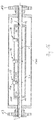
- Fig. 1b is greatly simplified an embodiment of such a transducer of the vibration type shown schematically.
- the transducer serves to generate in a medium flowing through mechanical reaction forces, eg mass flow-dependent Coriolis forces, density-dependent inertial forces and / or viscosity-dependent frictional forces measurable, esp. Sensory detectable, act back on the transducer. Derived from these reaction forces, for example, a mass flow rate m , a density ⁇ and / or a viscosity ⁇ of the medium can be measured in the manner known to those skilled in the art.
- the measuring transducer comprises a converter housing 100 and an inner part which is arranged in the converter housing 100 and which actually effects the physical-electrical conversion of the at least one parameter to be measured.
- the inner part comprises at least one - in the Fig. 1b shown embodiment, the only substantially straight - measuring tube 10, which can vibrate during operation and thereby, oscillating about a static rest position, repeatedly elastically deformed.
- the transducer in in Fig. 2 shown embodiment a single straight measuring tube and at least insofar as in its mechanical structure as well as its operating principle as in the above-mentioned EP-A 317 340 .
- US-B 70 73 396 US-B 70 40 179 .
- US-B 66 91 583 US-B 72 99 699 .
- US-B 70 73 396 US-B 70 40 179 .
- US-B 68 40 109 US-B 66 91 583 .
- the at least one measuring tube and, to that extent, an imaginary gravity line of the measuring tube extending within its lumen can be at least partially substantially S-, ⁇ -, or U-shaped or, as in the US-B 68 60 158 .
- Examples of further Meßrohrformen suitable for the realization of the invention are moreover inter alia in the above-mentioned US-A 52 87 754 . US-A 56 02 345 .
- US-B 67 58 102 US Pat. No. 5,731,527 .
- the measuring tube 10 In the operation of the transducer, the measuring tube 10, as usual in such Meßauf strictly to bending vibrations in the so-called Nutzmode - for example at a substantially natural natural frequency corresponding excitation frequency f exc - so excited that it is an imaginary - here to an imaginary longitudinal axis L of the transducer, which connects its inlet and outlet ends imaginary, substantially parallel or coincidental - Bieschwivelungsachse oscillates, at least partially recountbig essentially in accordance with a natural first natural mode.
- Coriolis be induced by means of vibrating in the manner described above measuring tube 10 in the medium flowing.
- a counteroscillator 20 is provided in the measuring transducer. This one is, as well as in Fig. 1b shown laterally spaced from the measuring tube 10 in the transducer and to form a - practically an inlet end of the measuring tube 10 defining - first coupling zone 11 # inlet side and the formation of a - practically an outlet end of the measuring tube 10 defining - second coupling zone 12 # outlet side respectively on the measuring tube 10 fixed.
- substantially parallel to the measuring tube 10 extending, possibly also arranged coaxially to this - counter-oscillator 20 may for example be tubular or substantially box-shaped, also executed.
- the counteroscillator 20 by means of at least one inlet-side first coupler 31 at the inlet end 11 # of the measuring tube 10 and by means of at least one outlet, esp.
- second coupler 32 at the outlet end 12 # of the measuring tube 10 is supported.
- Couplers 31, 32 may in this case serve, for example, simple nodal plates, which are fastened in a corresponding manner on the inlet side and outlet side respectively to measuring tube 10 and counteroscillator 20, for example by pressing on and / or soldering corresponding metal bodies according to the above-mentioned US-A 60 47 457 or US-B 61 68 069 ,
- the measuring tube 10 is also on a inlet side in the region of the first coupling zone 11 # opening straight first connecting pipe section 11 and on the outlet side in the region of the second coupling zone 12 # opening, in particular to the first connecting pipe section 11 substantially identical, straight second connecting pipe section 12th corresponding to the medium inlet or outlet - not shown here - connected process line, wherein an inlet end of the inlet side connecting pipe piece 11 practically form the inlet end of the transducer and an outlet end of the outlet side connecting pipe piece 12, the outlet end of the transducer.
- the measuring tube 10 and together with the two connecting pipe sections 11, 12 may be made in one piece, so that their manufacture can serve, for example, a single tubular semi-finished product.
- inlet tube piece 11 and outlet tube piece 12 are each formed by segments of a single, one-piece tube, these, if necessary, but also by means of individual, subsequently assembled, eg welded together, semifinished products are produced.
- any of the materials customary for such measuring sensors such as steel, Hastelloy, titanium, zirconium, tantalum, etc., can be used.
- the converter housing 100 may also serve to support the electronics housing 200 of the in-line meter with driver and evaluation electronics housed therein.
- the transducer is releasably mounted with the, for example, formed as a metallic pipe, process line, is also the inlet side connecting pipe piece 11 at its inlet end a first flange 13 of the Meßaufillons and the outlet side connecting pipe piece 12 at an outlet end, a second flange 14 of the Formed transducer.
- the connecting flanges 13, 14 can, as in the case of measuring transducers of the type described quite customary, also be integrated into the converter housing 100 at least partially at the end. If However, the connecting pipe pieces 11, 12 may otherwise be connected directly to the process line, eg by means of welding or brazing.
- the transducer further comprises at least one serving as a vibration exciter 16 - here acting centrally on the measuring tube - vibration transducer.
- Further suitable positions for oscillation converters serving as vibration exciters are, for example, those mentioned in the opening paragraph US-B 65 57 422 . US-A 60 92 429 . US-A 48 23 614 . US-B 62 23 605 or US-A 55 31 126 shown.
- the vibration exciter serves - driven by an excitation signal supplied by the driver electronics and, if appropriate, in conjunction with the evaluation electronics, suitably conditioned, eg with a regulated current and / or a regulated voltage - by means of the driver electronics fed electrical excitation energy E exc in an on the measuring tube 10, eg pulse-shaped or harmonic, acting and this in the manner described above deflecting excitation force F exc convert.
- suitable driver electronics are well known to those skilled in and eg in the US-A 47 77 833 , the US-A 48 01 897 , the US-A 48 79 911 or the US-A 50 09 109 shown.
- the excitation force F exc may, as is customary with such measuring sensors, be bidirectional or unidirectional and in the manner known to those skilled in the art, for example by means of a current and / or voltage control circuit, with respect to their amplitude and, for example by means of a phase-locked loop, with respect to their Frequency are set.
- the at least one measuring tube is excited at least temporarily in a Nutzmode by means of the Schwingungserregers16 in which it at least partially - especially predominantly or exclusively - bending vibrations around the inlet and outlet end of the measuring tube imaginary interconnected imaginary axis of vibration executes For example, with a single and / or a lowest of its resonance frequencies.
- the bending vibrations of the measuring tube have in the region of the inlet-side end of the measuring tube defining inlet-side coupling zone 11 # an inlet side node and in the region of the outlet end of the measuring tube defining outlet-side coupling zone 11 # an outlet-side node.
- the measuring tube 10 performs the bending oscillations relative to the counter-oscillator 20 and the longitudinal axis L.
- the transducer For detecting vibrations of the measuring tube 10, the transducer further comprises at least one further, serving as a first vibration sensor 17 - here on the inlet side of the measuring tube arranged -Schungungswandler for generating at least one vibration of the measuring tube 10 representing the first primary signal s 1 of the transducer.
- the transducer may further at least one - placed for example on the outlet side of the measuring tube and / or substantially identical to the vibration sensor 17 - additional second vibration sensor 18, the at least one further, for example outlet side, vibrations of at least one measuring tube 10 representing the second primary signal s 2 of the transducer supplies.
- the vibration transducer serving as the first vibration sensor 17 are arranged on the inlet side and the vibration transducer serving as the second vibration sensor 18 on the outlet side at least one measuring tube, so that the transducer can be used, for example, in a measurement system designed as Coriolis Massen pressflußMeß réelle.
- Each substantially identical design, vibration transducer are advantageously on one and the same side of the measuring tube 10 and arranged while so placed by each of the two coupling zone 11 #, spaced 12 # in the transducer in that they each have substantially the same distance to the center of the measuring tube 10 or respectively to the next of the two coupling zone 11 #, 12 #.
- connection lines are electrically connected to the aforementioned driver electronics or the mentioned evaluation electronics of the in-line measuring device by means of corresponding connection lines, which in turn are at least partially guided within the transducer housing, cf. this in particular also the above-mentioned US-A 2008/0250871 . US-A 2008/0223150 or. US-A 2008/0223149 ,
- the leads may be at least proportionally formed as electrical, at least partially wrapped in an electrical insulation wires, eg inform of "twisted pair" cables, ribbon cables and / or coaxial cables.
- the connection lines can also be formed, at least in sections, by means of conductor tracks of a, in particular flexible, optionally over-painted circuit board.
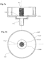
- transducer In the transducer according to the invention is further provided that at least one - possibly also each - of the aforementioned, serving as a vibration sensor or as a vibration exciter, vibration transducer 16, 17, 18, by means of a - attached to the measuring tube 10 - Magnet adopted 5 (-> 16, 17, or 18) is formed, which has a permanent magnet 51 a placed in a magnetic cup.
- the permanent magnet consisting at least partly of ferro-magnetic material may be made, for example, of a magnetic ceramic, such as ferrite and / or "rare earth", especially NdFeB (neodymium-iron-boron) or SmCo (samarium-cobalt), etc. while the magnetic cup 51b may at least partially be made of a magnetically conductive metallic alloy, for example, AINiCo (aluminum-nickel-cobalt) or a steel, such as Furthermore, starting from the cup base 51b ', there extends a cup wall 51b "of the magnetic cup 51b, for example a substantially circular cylindrical and / or tubular shape.
- a magnetically conductive metallic alloy for example, AINiCo (aluminum-nickel-cobalt) or a steel, such as Furthermore, starting from the cup base 51b ', there extends a cup wall 51b "of the magnetic cup 51b, for example a substantially circular cylindrical and / or tubular shape.
- the permanent magnet 51a which is here elongated and / or rod-shaped, is again in the FIGS. 2a and 2b shown schematically - placed within the magnetic cup 51b on a, for example, directly attached to the measuring tube 10, cup bottom 51b 'of the magnetic cup 51b, for example, substantially in a center of the cup bottom 51b'.
- cup wall 51b "of the magnetic cup 51b is formed substantially circular cylindrical and / or tubular, according to another embodiment of the invention is further provided to align permanent magnet 51a and cup wall 51b" to each other substantially coaxially extending.
- the vibration converter formed by means of the aforementioned magnetic device 5 further comprises a vis a vis of the permanent magnet - here according to the counteroscillator 20 fixed - coil 52; Alternatively, however, the coil 52 may also be fixed to the counter-oscillator 20 and in a corresponding manner to the corresponding permanent magnet 51a on the measuring tube 10.
- The, realized for example as a cylindrical coil, coil 52 is arranged as close to the permanent magnet 51a, in such a way that it is exposed to the magnetic field.
- the magnetic device 51 serves as a vibration sensor
- a variable measuring voltage is induced in the latter due to the relative movement of the permanent magnet 51a and the coil 52.
- the magnetic device 51 serves as a vibration exciter
- Coil and permanent magnet can be placed for example in the manner in the transducer and aligned with each other, that the permanent magnet is immersed in the manner of a solenoid plunger in the coil and is moved back and forth within the same.
- permanent magnet 51a and coil 52 of the least one vibration sensor are aligned with each other substantially coaxially.
- a holding device 51c which serves to fix the permanent magnet in the magnetic cup, which is rather oblong or rod-shaped in the exemplary embodiment shown here, is also provided which, at least in the installed state or when finished magnet device 5 is fixedly connected to the permanent magnet 51a, such as by force and / or shape and / or material bond.
- the holding device 51c has a holding head 51c 'for holding the permanent magnet facing the permanent magnet and a holding pin 51c "fixed to the holding head, and the holding bolt is further suitably fixed to the measuring tube 10 with its end facing away from the holding head.
- the measuring tube For holding the magnetic device on the measuring tube, for example, a pushed onto the measuring tube 10, the measuring tube substantially along one of the imaginary circumferential lines fixed, esp. Full circumference, spanning, esp. Metallic and / or substantially disc-shaped, fastener BE serve.
- Design and use of such fasteners for magnetic devices are known in the art, for example, from the above-mentioned US-A 60 47 457 . US-B 65 19 828 or US-B 72 99 699 ,
- the material used for the fastening element 30 may be, for example, a metal alloy compatible with the retaining bolt or the solder used for fixing it, for example, titanium or a steel, or a corresponding ceramic.
- Retaining bolt and fastener may, for example, cohesively, for example by means of solder joint, be connected to each other
- holding head 51c 'and the holding bolt 51c may be fixed together by means of a material connection, such as soldering or welding or gluing, but holding head 51c' and holding bolt 51c" may be fixed e.g. also be designed as a monolithic component made of one piece, held free of joints.
- permanent magnet 51a and holding head 51c ' can be fixed to one another by means of positive engagement and / or by means of material connection, in particular produced by soldering or adhesive bonding.
- the permanent magnet 51a and the holding head 51c ' but also be integrally formed, for example in the form of a monolithic sintered molded part or the permanent magnet by means of a formed between this and the holding head, esp. Repositionable, frictional connection with the holding device 51c be firmly connected.
- Fig. 2a, b or Fig. 4a, b schematically, is, for example, substantially frusto-conical or circular cylindrical trained, holding head 51c 'of the magnetic device 5 according to the invention also at least partially received by a provided in the cup bottom 51b 51 # #, in such a way that an outer contact surface C of the holding head 51c' and an inner contact surface B of the passage 51 # touch each other to form a frictional connection between the magnetic cup 51b and the holding device 51c.
- the frictional connection between the magnetic cup 51b and the holding device 51c can, for example, by thermal shrinking of the magnetic cup on the previously held in the implementation appropriately positioned holding head and / or by mixed plastic-elastic deformation of the magnetic cup, such as Pressing the same against the introduced into the implementation of the holding head, be prepared, for example, according to one of the above-mentioned US-A 60 47 457 .
- US-B 65 19 828 or US-B 72 99 699 presented method for fixing metal bodies.
- To increase the strength of the positive connection between magnetic cup and holding device can also, as for example in the US-B 72 99 699 proposed, additionally form-locking contours in the contact surfaces of implementation 51 # and / or holding head to be formed.
- the holding head at least partially as an outer cone and provided in the cup bottom passage at least partially formed as an inner cone, in such a way that the contacting contact surfaces of the holding head or passage to each other are substantially complementary.
- the retaining bolt of the holding device is provided with an external thread AG.
- a spring element FE placed between the clamping nut and the cup bottom for example as a spring ring or as a spring washer, can furthermore be used. It goes without saying that provided with the male thread AG portion of the retaining bolt is dimensioned so that a sufficiently large clamping force can be generated in the interaction of clamping nut, cup base and holding head.
- the holding device is designed as a collet engaging the permanent magnet.
- This is the holding head, as from the synopsis of Fig. 2a and 2b or 5 readily realized by means of two or by means of several, each designed as a clamping jaw head portions 51cA, 51cB and 51cC realized.
- the permanent magnet 51 a is, as from the synopsis of Fig. 2a, b and 5 or the Fig.
- FIG. 5 shown schematically, in a to the holding head 51c 'subsequent, optionally also at least partially provided with external thread AG, section at least one in the essentially in the direction of the longitudinal axis of the retaining bolt 51c "up to a permanent magnet 51a facing the edge of the holding head 51c 'extending longitudinal slot 51c'" has.
- the longitudinal slot 51c '" is slightly compressed when the magnet device 5 has been completed under the action of the clamping nut S and the bushing 51 # acting against the head parts.
- the permanent magnet can also be used Fig. 5 shown schematically, in its mounted in the installed state of the headboard end portion have an equally axially extending and slightly compressed in the installed state longitudinal slot.
- the permanent magnets 51a contacting inner surfaces of the jaws serving as a head part to the contacted outer surface of the permanent magnet 51a in Have significant complementary contour, so that the permanent magnet 51a and holding head touch each other as large as possible and so the intervening, ultimately the frictional connection producing frictional forces are increased.
- the pull-out or vibration resistance between the permanent magnet 51a and holding device 51c may be provided in their contacting surfaces also additionally form-fitting, for example formed as threads or annular grooves, contours, for example according to US-B 72 99 699 suggested way.
Description
Die Erfindung betrifft eine, insb. für einen Schwingungswandler und/oder für einen Meßaufnehmer vom Vibrationstyp geeignete, Magneteinrichtung mit einem ein Magnetfeld liefernden Permanentmagneten, einem mit dem Permanentmagneten fest verbundene Halteeinrichtung sowie mit einem Magnetbecher. Darüberhinaus betrifft die Erfindung einen mit wenigstens einer solche Magneteinrichtung ausgestatteten Meßaufnehmer vom Vibrationstyp für ein in einer Rohrleitung strömendes Medium.The invention relates to a, in particular for a vibration transducer and / or for a transducer of the vibration type suitable, magnetic device with a magnetic field-supplying permanent magnet, a permanently connected to the permanent magnet holding device and a magnetic cup. Moreover, the invention relates to a vibration-type transducer equipped with at least one such magnetic device for a medium flowing in a pipeline.
In der industriellen Meßtechnik werden, insb. auch im Zusammenhang mit der Regelung und Überwachung von automatisierten verfahrenstechnischen Prozessen, zur Ermittlung von charakteristischen Meßgrößen von in einer Prozeßleitung, beispielsweise einer Rohrleitung, strömenden Medien, beispielsweise von Flüssigkeiten und/oder Gasen, oftmals Meßsysteme verwendet, die mittels eines Meßaufnehmers vom Vibrationstyp und einer daran angeschlossenen, zumeist in einem separaten Elektronik-Gehäuse untergebrachten, Treiber- und Auswerteelektronik, im strömenden Medium Reaktionskräfte, beispielsweise Corioliskräfte, induzieren und von diesen abgeleitet ein die wenigstens eine Meßgröße, beispielsweise einem Massedurchfluß, einer Dichte, einer Viskosität oder einem anderen Prozeßparameter, entsprechend repräsentierendes Meßsignal erzeugen. Derartige - oftmals mittels eines In-Line-Meßgeräts in Kompaktbauweise mit integriertem Meßaufnehmer, wie etwa einem Coriolis-Massedurchflußmesser, gebildete - Meßsysteme sind seit langem bekannt und haben sich im industriellen Einsatz bewährt. Beispiele für solche Meßsysteme mit einem Meßaufnehmer vom Vibrationstyp oder auch einzelne Komponenten davon, sind z.B. in der
Im Betrieb des Meßsystems wird das wenigstens ein Meßrohr zwecks Generierung von durch das hindurchströmende Medium mit beeinflußten Schwingungsformen im Betrieb vibrieren gelassen. Zum Erregen von Schwingungen des wenigstens einen Meßrohrs weisen Meßaufnehmer vom Vibrationstyp des weiteren eine im Betrieb von einem von der erwähnten Treiberelektronik generierten und entsprechend konditionierten elektrischen Treibersignal, z.B. einem geregelten Strom und/oder einer geregelten Spannung, angesteuerte Erregeranordnung auf. Diese regt das Meßrohr mittels wenigstens eines im Betrieb von einem Erregerstrom durchflossenen elektromechanischen, insb. elektro-dynamischen, Schwingungserregers zu Biegeschwingungen im Nutzmode an. Desweiteren umfassen derartige Meßaufnehmer eine Sensoranordnung mit, insb. elektro-dynamischen, Schwingungssensoren zum zumindest punktuellen Erfassen einlaßseitiger und auslaßseitiger Schwingungen des wenigstens einen Meßrohrs, insb. denen im Coriolismode, und zum Erzeugen von vom zu erfassenden Prozeßparameter, wie etwa dem Massedurchfluß oder der Dichte, beeinflußten elektrischen Sensorsignalen. Neben den für das Erfassen von Vibrationen des Meßrohrs vorgesehenen Schwingungssensoren kann der Meßaufnehmer, wie u.a. auch in der
Als angeregte Schwingungsform - dem sogenannten Nutzmode - wird bei Meßaufnehmern mit gekrümmtem, z.B. U-, V- oder Ω-artig geformtem, Meßrohr üblicherweise jene Eigenschwingungsform gewählt, bei denen das Meßrohr zumindest anteilig bei einer niedrigsten natürlichen Resonanzfrequenz um eine gedachte Längsachse des Meßaufnehmers nach Art eines an einem Ende eingespannten Auslegers pendelt, wodurch im hindurchströmenden Medium vom Massendurchfluß abhängige Corioliskräfte induziert werden. Diese wiederum führen dazu, daß den angeregten Schwingungen des Nutzmodes, im Falle gekrümmter Meßrohre also pendelartigen Auslegerschwingungen, dazu gleichfrequente Biegeschwingungen gemäß wenigstens einer ebenfalls natürlichen zweiten Schwingungsform, dem sogenannten Coriolismode, überlagert werden. Bei Meßaufnehmern mit gekrümmtem Meßrohr entsprechen diese durch Corioliskräfte erzwungenen Auslegerschwingungen im Coriolismode üblicherweise jener Eigenschwingungsform, bei denen das Meßrohr auch Drehschwingungen um eine senkrecht zur Längsachse ausgerichtete gedachte Hochachse ausführt. Bei Meßaufnehmern mit geradem Meßrohr hingegen wird zwecks Erzeugung von massendurchflußabhängigen Corioliskräften oftmals ein solcher Nutzmode gewählt, bei dem das Meßrohr zumindest anteilig Biegeschwingungen im wesentlichen in einer einzigen gedachten Schwingungsebene ausführt, so daß die Schwingungen im Coriolismode dementsprechend als zu den Nutzmodeschwingungen koplanere Biegeschwingungen gleicher Schwingfrequenz ausgebildet sind. Aufgrund der Überlagerung von Nutz- und Coriolismode weisen die mittels der Sensoranordnung einlaßseitig und auslaßseitig erfaßten Schwingungen des vibrierenden Meßrohrs eine auch vom Massedurchfluß abhängige, meßbare Phasendifferenz auf. Üblicherweise werden die Meßrohre derartiger, z.B. in Coriolis-Massedurchflußmessern eingesetzte, Meßaufnehmer im Betrieb auf einer momentanen natürlichen Resonanzfrequenz der für den Nutzmode gewählten Schwingungsform, insb. bei konstantgeregelter Schwingungsamplitude, angeregt. Da diese Resonanzfrequenz im besonderen auch von der momentanen Dichte des Mediums abhängig ist, kann mittels marktüblicher Coriolis-Massedurchflußmesser neben dem Massedurchfluß zusätzlich auch die Dichte von strömenden Medien gemessen werden. Ferner ist es auch möglich, wie beispielsweise in der
Bei Meßaufnehmern mit einem einzigen Meßrohr kommuniziert letzteres zumeist über ein einlaßseitig einmündendes im wesentlichen gerades Verbindungsrohrstück sowie über ein auslaßseitig einmündendes im wesentlichen gerades Verbindungsrohrstück mit der Prozeßleitung. Ferner umfaßt jeder der gezeigten Meßaufnehmer mit einem einzigen Meßrohr jeweils wenigstens einen einstückigen oder mehrteilig ausgeführten, beispielsweise rohr-, kasten- oder plattenförmigen, Gegenschwinger, der unter Bildung einer ersten Kopplungszone einlaßseitig an das Meßrohr gekoppelt ist und der unter Bildung einer zweiten Kopplungszone auslaßseitig an das Meßrohr gekoppelt ist, und der im Betrieb im wesentlichen ruht oder zum Meßrohr gegengleich, also gleichfrequent und gegenphasig, oszilliert. Das mittels Meßrohr und Gegenschwinger gebildete Innenteil des Meßaufnehmers ist zumeist allein mittels der zwei Verbindungsrohrstücke, über die das Meßrohr im Betrieb mit der Prozeßleitung kommuniziert, in einem schutzgebenden Meßaufnehmer-Gehäuse gehaltert, insb. in einer Schwingungen des Innenteil relativ zum Meßrohr ermöglichenden Weise. Bei den beispielsweise in der
Die Erregeranordnung von Meßaufnehmern der in Rede stehenden Art weist üblicherweise wenigstens eine auf das wenigstens eine Meßrohr und den ggf. vorhandenen Gegenschwinger oder das ggf. vorhandene andere Meßrohr zumeist differentiell einwirkenden, Schwingungserreger dienende, zumeist elektrodynamische, Magneteinrichtung auf, während die Sensoranordnung einen als einlaßseitiger Schwingungssensor dienende einlaßseitige, zumeist ebenfalls elektrodynamische, Magneteinrichtung sowie wenigstens einen dazu im wesentlichen baugleichen, als auslaßseitiger Schwingungssensor dienenden auslaßseitige Magneteinrichtung umfaßt. Üblicherweise sind zumindest die als Schwingungssensor dienenden Magneteinrichtung im wesentlichen baugleich. Solche als Schwingungswandler dienende Magneteinrichtungen marktgängiger Meßaufnehmer vom Vibrationstyp sind mittels einer - bei Meßaufnehmern mit einem Meßrohr und einem daran gekoppelten Gegenschwinger zumeist an letzterem fixierten - Magnetspule sowie einen mit der wenigstens einen Magnetspule wechselwirkenden, insb. in diese eintauchenden, als Anker dienenden eher länglichen, insb. stabförmig ausgebildeten, Permanentmagneten gebildet, der entsprechend am zu bewegenden Meßrohr fixiert ist. Dies hat beispielsweise den Vorteil, daß mittels der Magneteinrichtungen die Schwingungsbewegungen zwischen dem vibrierenden Meßrohr und dessen Gegenpart, also dem ggf. vorhandenen Gegenschwinger oder dem ggf. vorhandenen anderen Meßrohr, differentiell erfaßt bzw. erzeugt werden können. Der Permanentmagnet und die als Erreger- bzw. Sensorspule dienende Magnetspule sind dabei üblicherweise so ausgerichtet, daß sie zueinander im wesentlichen koaxial verlaufen. Zudem ist bei herkömmlichen Meßaufnehmern die als Schwingungserreger dienende Magneteinrichtung üblicherweise derart ausgebildet und im Meßaufnehmer plaziert, daß sie im wesentlichen zentral an das wenigstens eine Meßrohr angreift. Dabei ist die als Schwingungserreger dienende Magneteinrichtungen, wie beispielsweise auch bei den in der
Bei Meßaufnehmern der in Rede stehenden Art ist es, wie u.a. auch in der
Bei marktgängigen Meßaufnehmern vom Vibrationstyp sind die als Schwingungssensoren dienenden Magneteinrichtungen, wie bereits angedeutet, oftmals zumindest insoweit im wesentlichen baugleich ausgebildet, wie die wenigstens eine als Schwingungserreger dienende Magneteinrichtung, als sie nach dem gleichen Wirkprinzip arbeiten. Dementsprechend sind auch die Magneteinrichtungen einer solchen Sensoranordnung zumeist jeweils mittels wenigstens einer - üblicherweise am ggf. vorhandene Gegenschwinger fixierten -, zumindest zeitweise von einem veränderlichen Magnetfeld durchsetzte und damit einhergehend zumindest zeitweise mit einer induzierten Meßspannung beaufschlagten sowie einem am Meßrohr fixierten, mit der wenigstens eine Magnetspule zusammenwirkenden stabförmigen Permanentmagneten gebildet, der das Magnetfeld liefert. Jede der vorgenannten Spulen ist zudem mittels wenigstens eines Paars elektrischer Anschlußleitungen mit der erwähnten Betriebs- und Auswerteelektronik des In-Line-Meßgeräts verbunden, die zumeist auf möglichst kurzem Wege von den Spulen über den Gegenschwinger hin zum Wandlergehäuse geführt sind.In the case of commercially available transducers of the vibration type, the magnetic devices serving as vibration sensors, as already indicated, are often substantially identical, at least insofar as the at least one magnetic device serving as vibration exciter, as they operate on the same operating principle. Correspondingly, the magnetic devices of such a sensor arrangement are usually each by means of at least one - usually at the existing counter-oscillator - at least temporarily interspersed by a variable magnetic field and concomitantly at least temporarily acted upon by an induced measuring voltage and fixed to the measuring tube, with the at least a magnetic coil co-operating rod-shaped permanent magnet is formed, which provides the magnetic field. Each of the aforementioned coils is also connected by means of at least one pair of electrical leads to the aforementioned operating and evaluation of the in-line measuring device, which are usually performed on the shortest path from the coils on the counteroscillator towards the converter housing.
Bei Magneteinrichtungen der vorgenannten Art ist der Permanentmagnet, etwa zwecks Homogenisierung des Spule und Permanentmagneten durchflutenden Magnetfelds sowie zwecks Vermeidung von störenden Streufeldern, üblicherweise innerhalb eines zumindest anteilig aus magnetisch leitfähigem Material bestehenden Magnetbecher plaziert und daselbst an einem Becherboden gehaltert, von dem ausgehend sich eine im wesentlichen rohrförmige, insb. kreiszylindrisch, ausgebildete Becherwand des Magnetbechers erstreckt. Üblicherweise ist der Permanentmagnet im wesentlichen in einem Zentrum des Becherbodens angeordnete und zumeist so an diesem fixiert, daß Permanentmagnet und Becherwand zueinander im wesentlichen koaxial verlaufend ausgerichtet sind.In magnetic devices of the aforementioned type of permanent magnet, for example, for the purpose of homogenization of the coil and permanent magnets flowing magnetic field and in order to avoid disturbing stray fields, usually placed within an at least partially composed of magnetically conductive material magnetic cup and there held on a cup base, starting from which in the substantially tubular, esp. Circular cylindrical, formed cup wall of the magnetic cup extends. Usually, the permanent magnet is arranged substantially in a center of the cup bottom and usually fixed thereto so that the permanent magnet and cup wall are aligned with each other substantially coaxially extending.
Zum Befestigen von Permanentmagnet und Magnetbecher kann bei Magneteinrichtungen der in Rede stehenden Art, wie etwa in der
Zur Vermeidung solcher Störungen des Magnetfeldes werden in Magneteinrichtungen marktgängiger Meßaufnehmer vom Vibrationstyp Permanentmagnet und Becherboden, wie auch in der
Ein Nachteil solcher stoffschlüssigen Verbindungen zwischen Permanentmagnet und Becherboden ist allerdings darin zusehen, daß, insb. auch wegen der Einbaulage des Permanentmagneten innerhalb des Magnetbechers wie auch den sehr geringen Abmessungen von Permanentmagneten und Magnetbecher, das Applizieren der den Stoffschluß letztlich herstellenden Materialien, etwa des Lotes bzw. des Klebers, einerseits und anderseits das hoch präzise Ausrichten des Permanentmagneten innerhalb des Magnetbechers mit erheblichen Schwierigkeiten verbunden und insoweit sehr aufwendig sein können. Zudem sind durch die zumeist sehr unterschiedlichen Materialien für Permanentmagnet bzw. Becherboden, insb. hinsichtlich Verarbeitbarkeit und erforderlicher Dauerfestigkeit über einen weiten thermischen und/der mechanischen Belastungsbereich, tatsächlich gut geeignete Lote bzw. Kleber nicht ohne weiteres verfügbar oder aber sehr teuer.A disadvantage of such cohesive connections between permanent magnet and cup base is, however, watch that, especially because of the installation position of the permanent magnet within the magnetic cup as well as the very small dimensions of permanent magnets and magnetic cup, the application of the material connection ultimately producing materials, such as the solder or the adhesive, on the one hand, and on the other hand, the highly precise alignment of the permanent magnet within the magnetic cup associated with considerable difficulties and can be very costly in this respect. In addition, due to the mostly very different materials for permanent magnet or cup base, esp. In terms of processability and fatigue strength required over a wide thermal and / or mechanical load range, actually well-suited solders or adhesives are not readily available or very expensive.
Eine Aufgabe der Erfindung besteht daher darin, für Meßaufnehmer vom Vibrationstyp geeignete Magneteinrichtungen der vorgenannten Art dahingehend zu verbessern, daß zum einen deren Montage vereinfacht und zum anderen auch die Dauerfestigkeit solcher Magneteinrichtungen bzw. deren Betriebstemperaturbereich weiter ausgedehnt werden kann.An object of the invention is therefore to improve for transducers of the vibration type suitable magnetic devices of the aforementioned type to the effect that on the one hand simplifies their assembly and on the other, the fatigue strength of such magnetic devices or their operating temperature range can be further expanded.
Zur Lösung der Aufgabe besteht die Erfindung in einer Magneteinrichtung, insb. für einen Schwingungswandler und/oder für einen Meßaufnehmer vom Vibrationstyp, die
- einen ein Magnetfeld liefernden, insb. stabförmigen, Permanentmagneten,
- einen mit dem Permanentmagneten, insb. durch Kraft- und/oder Form- und/oder Stoffschluß, fest verbundene, insb. als Spannzange ausgebildete, Halteeinrichtung mit
- -- einem dem Permanentmagneten zugewandten, insb. zumindest anteilig als Außenkonus ausgebildeten, Haltekopf zum Haltern des Permanentmagneten, und
- -- einem am Haltekopf fixierten, insb. ein Außengewinde aufweisenden und/oder in einem sich an das Haltekopf anschließenden Abschnitt längsgeschlitzten, Haltebolzen, sowie
- einen Magnetbecher mit
- - einem Becherboden und
- - einer sich vom Becherboden aus erstreckenden, insb. im wesentlichen kreiszylindrisch und/oder rohrförmig ausgebildeten, Becherwand umfaßt,
- wobei der Haltekopf der Halteeinrichtung zumindest teilweise von einer im Becherboden vorgesehenen, insb. zumindest anteilig als Innenkonus ausgebildeten, Durchführung aufgenommen ist, und
- wobei eine äußere Kontaktfläche des Haltekopfs und eine innere Kontaktfläche der Durchführung einander unter Bildung eines Kraftschlusses zwischen Magnetbecher und Halteeinrichtung berühren, insb. in einer die Durchführung aufweitenden und/oder den Becherboden elastisch verformenden Weise.
- a magnetic field supplying, esp. rod-shaped, permanent magnets,
- one with the permanent magnet, in particular by force and / or form and / or material bond, firmly connected, esp. Designed as a collet, holding device with
- - A permanent magnet facing, esp. At least partially formed as an outer cone, holding head for holding the permanent magnet, and
- - One on the holding head fixed, esp. An external thread having and / or longitudinally slotted in a subsequent to the holding head section, retaining bolts, and
- a magnetic cup with
- - a cup bottom and
- a cup wall extending from the bottom of the cup, in particular substantially circular-cylindrical and / or tubular, comprises
- wherein the holding head of the holding device is at least partially accommodated by a provided in the cup bottom, esp. At least partially formed as an inner cone, implementation, and
- wherein an outer contact surface of the holding head and an inner contact surface of the implementation of each other to form a frictional connection between the magnetic cup and the holding device touch, esp. In a widening the implementation and / or the cup bottom elastically deforming manner.
Darüber hinaus besteht die Erfindung in einem Meßaufnehmer vom Vibrationstyp für ein in einer Rohrleitung strömendes Medium, welcher Meßaufnehmer wenigstens ein zumindest zeitweise vibrierendes Meßrohr zum Führen von zu messendem Medium, sowie wenigstens einen, insb. als elektrodynamischer Schwingungserreger oder als elektrodynamischer Schwingungssensor dienenden, am wenigstens einen Meßrohr gehalterten Schwingungswandler für Vibrationen des wenigstens einen Meßrohrs umfaßt, wobei der wenigstens eine Schwingungswandler mittels vorgenannter Magneteinrichtung gebildet ist.In addition, the invention consists in a transducer of the vibration type for a medium flowing in a pipeline, which Meßaufnehmer at least one at least temporarily vibrating measuring tube for guiding medium to be measured, and at least one, esp. As electrodynamic vibration exciter or as electrodynamic vibration sensor, at least a measuring tube Erten held vibration transducer of the at least one measuring tube, wherein the at least one vibration transducer is formed by means of the aforementioned magnetic device.
Nach einer ersten Ausgestaltung der Magneteinrichtung der Erfindung ist vorgesehen, daß der Haltebolzen der Halteeinrichtung ein Außengewinde aufweist, und daß der Haltekopf der Halteeinrichtung mittels einer auf den Haltebolzen aufgeschraubten Spannmutter gegen den Becherboden gedrückt gehalten ist. Diese Ausgestaltung der Erfindung weiterbildend ist ferner vorgesehen, daß zwischen Spannmutter und Becherboden ein, insb. als Federring oder als Federscheibe ausgebildetes, Federelement plaziert ist.According to a first embodiment of the magnetic device of the invention it is provided that the retaining bolt of the holding device has an external thread, and that the holding head of the holding device is held pressed against the cup base by means of a screwed onto the retaining bolt clamping nut. This embodiment of the invention further provides that between clamping nut and cup ground a, esp. As a spring ring or spring washer designed, spring element is placed.
Nach einer zweiten Ausgestaltung der Magneteinrichtung der Erfindung ist vorgesehen, daß der Haltekopf mittels wenigstens zweier oder mehrerer, jeweils als Spannbacke ausgebildeten Kopfteilen gebildet ist. Diese Ausgestaltung der Erfindung weiterbildend ist ferner vorgesehen, daß der Permanentmagnet mit einem von dessen Enden zwischen den wenigstens zwei Kopfteilen plaziert ist, und daß die wenigstens zwei Kopfteile unter Bildung eines, insb. im Zusammenspiel von Spannmutter und Durchführung sowie den wenigstens zwei Kopfteilen erzwungenen, Kraftschlusses zwischen Permanentmagnet und Haltekopf jeweils gegen den Permanentmagnet gedrückt gehalten sind.According to a second embodiment of the magnetic device of the invention it is provided that the holding head is formed by means of at least two or more, each formed as a clamping jaw head parts. This embodiment of the invention further provides that the permanent magnet is placed with one of its ends between the at least two head parts, and that the at least two head parts to form a, esp. In the interaction of clamping nut and implementation and the at least two headboards forced, Frictional connection between the permanent magnet and the holding head are kept pressed against the permanent magnet.
Nach einer dritten Ausgestaltung der Magneteinrichtung der Erfindung ist vorgesehen, daß der Kraftschluß zwischen Magnetbecher und Halteeinrichtung durch thermisches Aufschrumpfen des Magnetbechers auf die Halteeinrichtung, insb. den Haltekopf, hergestellt ist.According to a third embodiment of the magnetic device of the invention, it is provided that the frictional connection between magnetic cup and holding device by thermal shrinkage of the magnetic cup on the holding device, esp. The holding head is made.
Nach einer vierten Ausgestaltung der Magneteinrichtung der Erfindung ist vorgesehen, daß Permanentmagnet und Haltekopf mittels, insb. durch wiederlösbaren, Kraftschluß und/oder mittels Formschluß und/der mittels, insb. durch Lotverbindung oder Klebverbindung hergestellten, Stoffschluß, aneinander fixiert sind.According to a fourth embodiment of the magnetic device of the invention, it is provided that the permanent magnet and holding head are fixed to one another by, in particular, releasable, frictional and / or positive locking and / or by means of, in particular by solder connection or adhesive bond, fabric bond.
Nach einer fünften Ausgestaltung der Magneteinrichtung der Erfindung ist vorgesehen, daß die Becherwand des Magnetbechers wenigstens einen, insb. sich bis zu einem zum Becherboden distalen Rand der Becherwand erstreckenden, Schlitz aufweist.According to a fifth embodiment of the magnetic device of the invention, it is provided that the cup wall of the magnetic cup at least one, esp. Up to a distal to the cup bottom edge of the cup wall extending slot.
Nach einer sechsten Ausgestaltung der Magneteinrichtung der Erfindung ist vorgesehen, daß der Permanentmagnet zumindest anteilig, insb. überwiegend oder vollständig, aus einer Seltenenerde, insb. NdFeB, SmCo oder dergleichen, besteht; und/oder
- wobei der Permanentmagnet zumindest anteilig, insb. überwiegend oder vollständig, aus Ferrit oder AlNiCo besteht.
- wherein the permanent magnet consists at least proportionally, in particular predominantly or completely, of ferrite or AlNiCo.
Nach einer siebenten Ausgestaltung der Magneteinrichtung der Erfindung ist vorgesehen, daß der Magnetbecher zumindest anteilig, insb. überwiegend oder vollständig, aus einem Stahl, insb. einem Automatenstahl oder einem Baustahl, besteht; und/oder daß der Magnetbecher zumindest anteilig, insb. überwiegend oder vollständig, aus Ferrit besteht.According to a seventh embodiment of the magnetic device of the invention it is provided that the magnetic cup at least partially, esp. Mainly or completely, from a steel, esp. A free cutting steel or a mild steel exists; and / or that the magnetic cup consists at least partially, in particular predominantly or completely, of ferrite.
Nach einer ersten Ausgestaltung des Meßaufnehmers der Erfindung ist vorgesehen, daß die Magneteinrichtung via Haltebolzen mit dem wenigstens einen Meßrohr mechanisch gekoppelt ist.According to a first embodiment of the Meßaufnehmers of the invention it is provided that the magnetic device is mechanically coupled via retaining bolts with the at least one measuring tube.
Nach einer zweiten Ausgestaltung des Meßaufnehmers der Erfindung weist der wenigstens eine Schwingungswandler weiters eine dem Magnetfeld des Permanentmagneten ausgesetzte Zylinderspule aufweist.According to a second embodiment of the measuring transducer of the invention, the at least one vibration transducer further comprises a cylindrical coil exposed to the magnetic field of the permanent magnet.
Ein Vorteil der Erfindung besteht u.a. darin, daß die Magneteinrichtung einen Einsatz eines damit ausgestatteten Meßaufnehmers vom Vibrationstyp in einem In-Line-Meßgerät zum Messen und/oder Überwachen wenigstens eines Parameters, insb. eines Massendurchflusse, m, einer Dichte, ρ, und/oder einer Viskosität, η, eines in einer Rohrleitung strömenden Mediums, insb. einem Coriolis-Massendurchflußmeßgerät, einem Dichtemeßgerät, einem Viskositätsmeßgerät oder dergleichen auch bei extremen Betriebstemperaturen von zumindest zeitweise mehr als 200°C und/oder von zumindest zeitweise weniger als -50°C ermöglicht. Zudem können der Aufbau bzw. die Montage von Magneteinrichtungen der in Rede stehenden Art erheblich vereinfacht und damit die Herstellungskosten von Meßaufnehmern vom Vibrationstyp insgesamt verringert werden.One advantage of the invention is, inter alia, that the magnet device comprises an insert of a vibration-type transducer equipped therewith in an in-line gauge for measuring and / or monitoring at least one parameter, esp. Mass flow, m, density, ρ , and / or a viscosity, η , of a medium flowing in a pipeline, in particular a Coriolis mass flowmeter, a densitometer, a viscometer or the like, even at extreme operating temperatures of at least temporarily greater than 200 ° C and / or at least temporarily less than -50 ° C allows. In addition, the construction or assembly of magnetic devices of the type in question can be considerably simplified and thus the manufacturing cost of vibration-type transducers can be reduced overall.
Nachfolgend werden die Erfindung und vorteilhafte Ausgestaltungen derselben anhand eines Ausführungsbeispiels erläutert, das in den Figuren der Zeichnung dargestellt ist; gleiche Teile sind in den Figuren im übrigen mit gleichen Bezugszeichen versehen. Falls es der Übersichtlichkeit dienlich ist, wird auf bereits erwähnte Bezugszeichen in nachfolgenden Figuren verzichtet. Im einzelne sind in:
Nachfolgend werden die Erfindung und weitere Vorteile anhand eines Ausführungsbeispiels erläutert, das in den Figuren der Zeichnung dargestellt ist. Gleiche Teile sind in den Figuren mit gleichen Bezugszeichen versehen. Falls es der Übersichtlichkeit dienlich ist, wird auf bereits erwähnte Bezugszeichen in nachfolgenden Figuren verzichtet.
- Fig. 1a
- zeigt schematisch ein In-Line-Meßgerät für in Rohrleitungen strömende Medien in einer perspektivischen Seitenansicht;
- Fig. 1b
- zeigt schematisch in einer geschnitten Seitenansicht einen für ein In-Line-Meßgerät gemäß der
Fig. 1a geeigneten Meßaufnehmer vom Vibrations-Typ; - Fig. 2a, b
- zeigen schematisch eine Magneteinrichtung für einen Meßaufnehmer gemäß den
Fig. 1b in einer geschnittenen Seitenansicht (2a) bzw. in einer Aufsicht (2b); - Fig. 3a, b
- zeigen schematisch in teilweise geschnittener Seitenansicht (3a) bzw. in einer Aufsicht (3b) eine weitere Variante einer für einen Meßaufnehmer gemäß den
Fig. 1b geeigneten Magneteinrichtung; - Fig. 4
- zeigt schematisch in einer Aufsicht noch eine weitere Variante einer für einen Meßaufnehmer gemäß den
Fig. 1b geeigneten Magneteinrichtung; und - Fig. 5
- zeigt schematisch eine erfindungsgemäße Magneteinrichtung in Explosionsdarstellung.
Hereinafter, the invention and further advantages will be explained with reference to an embodiment which is illustrated in the figures of the drawing. Identical parts are provided in the figures with the same reference numerals. If it is useful for the sake of clarity, reference numerals already mentioned are omitted in the following figures.
- Fig. 1a
- schematically shows an in-line meter for piping flowing media in a perspective side view;
- Fig. 1b
- schematically shows in a sectional side view one for an in-line measuring device according to the
Fig. 1a suitable vibration-type transducer; - Fig. 2a, b
- schematically show a magnetic device for a transducer according to the
Fig. 1b in a sectional side view (2a) and in a plan view (2b); - Fig. 3a, b
- show schematically in partially sectioned side view (3a) and in a plan view (3b) a further variant of a for a transducer according to the
Fig. 1b suitable magnetic device; - Fig. 4
- shows schematically in a plan yet another variant of a for a transducer according to the
Fig. 1b suitable magnetic device; and - Fig. 5
- schematically shows a magnetic device according to the invention in an exploded view.
In der
In
Zum Führen des Mediums umfaßt das Innenteil wenigstens ein - im in den
Im Betrieb des Meßaufnehmers wird das Meßrohr 10, wie bei derartigen Meßaufnehmern üblich, zu Biegeschwingungen im sogenannten Nutzmode - beispielsweise bei einer im wesentlichen einer natürlichen Resonanzfrequenz entsprechenden Erregerfrequenz fexc - so angeregt, daß es sich, um eine gedachte - hier zu einer gedachten Längsachse L des Meßaufnehmers, die dessen Einlaß- und Auslaßende imaginär verbindet, im wesentlichen parallele oder auch koinzidente - Biegeschwingungsachse oszillierend, zumindest anteilig im wesentlichen gemäß einer natürlichen ersten Eigenschwingungsform ausbiegt. Für den betriebsmäßig vorgesehenen Fall, daß das Medium in der Prozeßleitung strömt und somit der Massedurchfluß m von Null verschieden ist, werden mittels des in vorbeschriebener Weise vibrierenden Meßrohrs 10 im hindurchströmenden Medium auch Corioliskräfte induziert. Diese wiederum wirken auf das Meßrohr 10 zurück und bewirken so eine zusätzliche, sensorisch erfaßbare Verformung desselben im wesentlichen gemäß einer natürlichen zweiten Eigenschwingungsform. Eine momentane Ausprägung dieses sogenannten, dem angeregten Nutzmode gleichfrequent überlagerten Coriolismodes ist dabei, insb. hinsichtlich ihrer Amplituden, auch vom momentanen Massedurchfluß m abhängig. Als zweite Eigenschwingungsform kann, wie bei deratigen Meßaufnehmern mit geradem Meßrohr üblich, z.B. die Eigenschwingungsform eines zum Nutzmode im wesentlichen komplanaren anti-symmetrischen Biegeschwingungsmodes sein.In the operation of the transducer, the measuring
Zur Minimierung von auf das Meßrohr 10 wirkenden Störeinflüssen wie auch zur Reduzierung von seitens des Meßaufnehmers an die angeschlossene Prozeßleitung abgegebener Schwingungsenergie ist im Meßaufnehmer des weiteren ein Gegenschwinger 20 vorgesehen. Dieser ist, wie auch in
Wie in der
Wie aus der Zusammenschau der
Zum Anregen mechanischer Schwingungen des Meßrohrs 10, insb. den Biegeschwingungen im Nutzmode, sowie des ggf. vorhandenen Gegenschwingers 20 umfaßt der Meßaufnehmer ferner wenigstens einen als Schwingungserreger 16 dienenden - hier mittig auf das Meßrohr einwirkenden - Schwingungswandler. Weitere geeignete Postionen für als Schwingungserreger dienende Schwingungswandler sind z.B. in den eingangs erwähnten
Gemäß einer weiteren Ausgestaltung der Erfindung ist das wenigstens eine Meßrohr im Betrieb mittels des Schwingungserregers16 zumindest zeitweise in einem Nutzmode angeregt, in dem es zumindest anteilig - insb. überwiegend oder ausschließlich - Biegeschwingungen um die Einlaß- und Auslaßende des Meßrohrs imaginär miteinander verbindende gedachte Schwingungsachse ausführt, beispielsweise mit einer einzigen und/oder einer niedrigsten seiner Resonanzfrequenzen. Die Biegeschwingungen des Meßrohrs weisen dabei im Bereich der das einlaßseitige Ende des Meßrohrs definierenden einlaßseitigen Kopplungszone 11# einen einlaßseitigen Schwingungsknoten und im Bereich der das auslaßseitige Ende des Meßrohrs definierenden auslaßseitigen Kopplungszone 11# einen auslaßseitigen Schwingungsknoten auf. Bei dem in
Zum Erfassen von Schwingungen des Meßrohrs 10 weist der Meßaufnehmer ferner wenigstens einen weiteren, als erster Schwingungssensor 17 dienenden - hier einlaßseitig des Meßrohrs angeordneten -Schwingungswandler zum Erzeugen wenigstens eines Vibrationen des Meßrohrs 10 repräsentierenden ersten Primärsignals s1 des Meßaufnehmers auf. Wie bei Meßsystemen der in Rede stehenden Art üblich, kann der Meßaufnehmer ferner wenigstens einen - beispielsweise auslaßseitig am Meßrohrs plazierten und/oder zum Schwingungssensor 17 im wesentlichen baugleichen - zusätzlichen zweiten Schwingungssensor 18 aufweisen, der wenigstens ein weiteres, beispielsweise auslaßseitige, Vibrationen des wenigstens einen Meßrohrs 10 repräsentierendes zweites Primärsignal s2 des Meßaufnehmers liefert. Im hier gezeigten Ausführungsbeispiel sind der als erster Schwingungssensor 17 dienende Schwingungswandler einlaßseitig und der als zweiter Schwingungssensor 18 dienende Schwingungswandler auslaßseitig am wenigstens einen Meßrohr angeordnet, so daß der Meßaufnehmer beispielsweise auch in einem als Coriolis-MassendurchflußMeßgerät ausgebildeten Meßsystem verwendet werden kann. Die beiden als Schwingungssensoren 17, 18 dienenden, insb. einander im wesentlichen baugleich ausgebildeten, Schwingungswandler sind dabei in vorteilhafter Weise auf ein und derselben Seite am Meßrohr 10 und angeordnet und dabei so von jeder der beiden Kopplungszone 11#, 12# beabstandet im Meßaufnehmer plaziert, daß sie jeweils im wesentlichen den gleichen Abstand zur Mitte des Meßrohrs 10 bzw. zur jeweils nächsten der beiden Kopplungszone 11#, 12# aufweisen.For detecting vibrations of the measuring
Die vorgenannten Schwingungswandler sind mit der erwähnten Treiber-Elektronik bzw. der erwähnten Auswerte-Elektronik des In-Line-Meßgeräts mittels entsprechende Anschlußleitungen elektrisch verbunden, die wiederum zumindest abschnittsweise innerhalb des Wandlergehäuses geführt sind, vgl. hierzu im besonderen auch die eingangs erwähnten
Beim erfindungsgemäßen Meßaufnehmer ist ferner vorgesehen, daß zumindest einer - ggf. auch jeder - der vorgenannten, als Schwingungssensor bzw. als Schwingungserreger dienenden, Schwingungswandler 16, 17, 18, mittels einer - beispielsweise am Meßrohr 10 befestigten - Magneteinrichtung 5 (->16, 17, bzw. 18) gebildet ist, die einen in einem Magnetbecher plazierten Permanentmagneten 51a aufweist.In the transducer according to the invention is further provided that at least one - possibly also each - of the aforementioned, serving as a vibration sensor or as a vibration exciter,
Der zumindest anteilig aus ferro-magnetischem Material bestehende Permanentmagnet kann beispielsweise aus einer magnetischen Keramik, wie etwa Ferrit und/oder "Seltener Erde", insb. NdFeB (Neodym-Eisen-Bor) oder SmCo (Samarium-Cobalt) etc., hergestellt sein, während der Magnetbecher 51b zumindest anteilig aus einer magnetisch leitfähigen metallischen Legierung bestehen kann, beispielsweise also aus AINiCo (Aluminium-Nickel-Cobalt) oder einem Stahl, wie etwa einem Automatenstahl oder einem Baustahl, Ausgehend vom Becherboden 51b' erstreckt sich ferner eine, beispielsweise im wesentlichen kreiszylindrisch und/oder rohrförmig ausgebildete, Becherwand 51b" des Magnetbechers 51b. Der - hier länglich und/oder stabförmig ausgebildete - Permanentmagnet 51a wiederum ist - wie in den
Der mittels vorgenannter Magneteinrichtung 5 gebildete Schwingungswandler weist ferner eine vis a vis des Permanentmagneten - hier entsprechend am Gegenschwinger 20 fixierte - Spule 52 auf; alternativ dazu können die Spule 52 aber auch am Gegenschwinger 20 und in entsprechender Weise der mit dieser korrespondierende Permanentmagnet 51a am Meßrohr 10 fixiert sein.The vibration converter formed by means of the aforementioned
Die, beispielsweise als Zylinderspule realisierte, Spule 52 ist möglichst nah zum Permanentmagneten 51a angeordnet, und zwar so, daß sie dessen Magnetfeld ausgesetzt ist. Für den Fall, daß die Magneteinrichtung 51 als Schwingungssensor dient, wird infolge der Relativbewegung von Permanentmagnet 51a und Spule 52 in letzterer eine veränderliche Meßspannung induziert. Für den anderen Fall, daß die Magneteinrichtung 51 als Schwingungserreger dient, wird mittels des an die Spule 52 angelegten Erregersignals die die Vibrationen des Meßrohrs bewirkende Erregerkraft Fexc erzeugt. Spule und Permanentmagnet können z.B. in der Weise im Meßwandler plaziert und zueinander ausgerichtet sein, daß der Permanentmagnet nach Art eines Tauchankers in die Spule eintaucht und innerhalb derselben hin und her bewegt ist. Gemäß einer weiteren Ausgestaltung der Erfindung sind Permanentmagnet 51a und Spule 52 des wenigstes eine Schwingungssensors zueinander im wesentlichen koaxial verlaufend ausgerichtet.The, realized for example as a cylindrical coil,
Bei der erfindungsgemäßen Magneteinrichtung ist ferner eine dem Fixieren des - im hier gezeigten Ausführungsbeispiel eher länglich bzw. stabförmig ausgebildeten - Permanentmagneten im Magnetbecher dienende Halteeinrichtung 51c vorgesehen, die zumindest im eingebauten Zustand bzw. bei fertiggestellter Magneteinrichtung 5 mit dem Permanentmagneten 51a fest verbunden ist, etwa durch Kraft- und/oder Form- und/oder Stoffschluß. Die Halteeinrichtung 51c weist einen dem Permanentmagneten zugewandten und diesen kontaktierenden Haltekopf 51c' zum Haltern des Permanentmagneten sowie einen am Haltekopf fixierten Haltebolzen 51c" auf. Der Haltebolzen ist ferner mit seinem dem Haltekopf abgewandten Ende am Meßrohr 10 geeignet fixiert.In the case of the magnetic device according to the invention, a holding
Zum Haltern der Magneteinrichtung am Meßrohr kann beispielsweise ein auf das Meßrohr 10 aufgeschobenes, das Meßrohr im wesentlichen entlang einer von dessen gedachten Umfangslinien fest, insb. vollumfänglich, umspannendes, insb. metallisches und/oder im wesentlichen scheibenförmiges, Befestigungselement BE dienen. Aufbau und Verwendung solcher Befestigungselemente für Magneteinrichtungen sind dem Fachmann bekannt, beispielsweise auch aus der eingangs erwähnten
Ebenso können auch der Haltekopf 51c' und der Haltebolzen 51c" mittels stoffschlüssiger Verbindung, wie etwa Löten oder Schweißen oder Kleben, aneinander fixiert sein; Haltekopf 51c' und Haltebolzen 51c" können aber z.B. auch als aus einem Stück gefertigtes, frei von Fügestellen gehaltenes monolithisches Bauteil ausgebildet sein. Gleichermaßen können Permanentmagnet 51a und Haltekopf 51c' mittels Formschluß und/der mittels, insb. durch Lotverbindung oder Klebverbindung hergestellten, Stoffschluß, aneinander fixiert sein. Alternativ dazu können der Permanentmagnet 51a und der Haltekopf 51c' aber auch einstückig ausgebildet sein, beispielsweise in Gestalt eines monolithischen Sinterformteils oder kann der Permanentmagnet mittels eines zwischen diesem und dem Haltekopf gebildeten, insb. wiederlösbaren, Kraftschlusses mit der Halteeinrichtung 51c fest verbunden sein.Likewise, also the holding
Wie in
Gemäß einer anderen Ausgestaltung der Erfindung sind, wie in
Gemäß einer weiteren Ausgestaltung der Erfindung ist die Halteeinrichtung als eine den Permanentmagneten greifende Spannzange ausgebildet. Dafür ist der Haltekopf, wie aus der Zusammenschau der
Claims (14)
- Magnetic assembly, particularly for a vibration transducer and/or a vibronic-type sensor, said assembly comprising:- a permanent magnet (51a), particularly rod-shaped, generating a magnetic field,- a retaining unit (51c) connected to the permanent magnet in a fixed manner, particularly by means of a force-type connection and/or a positive locking connection and/or a material bond, said retaining unit (51c) particularly being designed as a collet, with-- a retaining head (51c') designed to hold the permanent magnet, said retaining head facing towards the permanent magnet and particularly being designed, at least in part, as an exterior cone, and-- a retaining bolt (51c") fixed on the retaining head, said bolt particularly having an outer thread and/or being slotted longitudinally in a section that continues on from the retaining head, as well as- a magnetic cup (51b) with-- a cup base (51b') and-- a cup wall (51b") that extends from the cup base and has an essentially circular cylindrical and/or tubular design,- wherein the retaining head of the retaining assembly is held at least partially by a feedthrough (51#) that is provided in the cup base, being designed at least in part as an interior cone, and- wherein an outer contact surface of the retaining head (C) and an inner contact surface of the feedthrough (B) touch one another forming a force-type connection between the magnetic cup and the retaining assembly, particularly in a manner that expands the feedthrough and/or elastically deforms the cup base.
- Magnetic assembly as claimed in the previous claim,- wherein the retaining bolt of the retaining assembly has an outer thread (AG), and- wherein the retaining head of the retaining assembly is kept pressed against the cup base by a clamping nut (S) screwed onto the retaining bolt.
- Magnetic assembly as claimed in the previous claim, wherein a spring element (FE) is positioned between the clamping nut and the cup base, particularly a spring element designed as a spring ring or spring washer.
- Magnetic assembly as claimed in one of the previous claims, wherein the retaining head (51c') is formed by at least two or more head parts (51cA, 51cB, 51cC) which are each designed as a clamping jaw.
- Magnetic assembly as claimed in the previous claim,- wherein the permanent magnet is positioned with one of its ends between the at least two head parts, and- wherein the at least two head parts are each kept pressed against the permanent magnet by the formation of a force-type connection between the permanent magnet and the retaining head, particularly created by the interaction between the clamping nut and feedthrough as well as the at least two head parts.
- Magnetic assembly as claimed in one of the previous claims, wherein the force-type connection between the magnetic cup and the retaining assembly is established by thermally shrinking the magnetic cup onto the retaining assembly, particularly the retaining head.
- Magnetic assembly as claimed in one of the previous claims, wherein the permanent magnet and the retaining head are fixed onto one another by means of a, particularly releasable, force-type connection, and/or a positive locking connection and/or a material bond particularly formed by means of a solder connection or adhesive connection.
- Magnetic assembly as claimed in one of the previous claims, wherein the cup wall (51b') of the magnetic cup has at least one slot (511b'"), said slot particularly extending to a distal edge of the cup wall, in relation to the cup base.
- Magnetic assembly as claimed in one of the previous claims,- wherein the permanent magnet is made at least partially, particularly primarily or completely, from a rare earth, particularly NdFeB, SmCo, or similar; and/or- wherein the permanent magnet is made at least partially, particularly primarily or completely, from ferrite or AlNiCo.
- Magnetic assembly as claimed in one of the previous claims,- wherein the magnetic cup is made at least partially, particularly primarily or completely, from a steel, particularly a machining steel or a structural steel; and/or- wherein the magnetic cup is made at least partially, particularly primarily or completely, from ferrite.
- Vibronic-type sensor for a medium flowing through a pipe, said sensor comprising:- at least one measuring tube (10), which vibrates at least temporarily, designed to conduct medium to be measured, as well as- at least one vibration transducer, which is fixed on at least one measuring tube, for vibrations of the at least one measuring tube, said vibration transducer particularly serving as an electrodynamic vibration exciter or as an electrodynamic vibration sensor, wherein the at least one vibration transducer has a magnetic assembly as claimed in one of the Claims 1 to 10.
- Sensor as claimed in the previous claim, wherein the magnetic assembly is mechanically coupled to the at least one measuring tube via retaining bolts.
- Sensor as claimed in one of the previous Claims 11 to 12, wherein the at least one vibration transducer further comprises a cylindrical coil that is exposed to the magnetic field of the permanent magnet.
- Use of a sensor as claimed in one of the Claims 11 to 13 in an inline measuring device to measure and/or monitor at least one parameter, particularly a mass flow, m, a density, ρ, and/or a viscosity, η, of a medium flowing through a pipe, particularly a Coriolis mass flowmeter, a density meter, a viscosity meter or similar, particularly at an operating temperature which is at least temporarily greater than 200 °C and/or at least temporarily less than -50 °C.
Applications Claiming Priority (2)
| Application Number | Priority Date | Filing Date | Title |
|---|---|---|---|
| DE102008044186A DE102008044186A1 (en) | 2008-11-28 | 2008-11-28 | Magnetic device and transducer of the vibration type with such a magnetic device |
| PCT/EP2009/064386 WO2010060731A1 (en) | 2008-11-28 | 2009-10-30 | Magnet device and vibration-type measuring sensor having such a magnet device |
Publications (2)
| Publication Number | Publication Date |
|---|---|
| EP2350577A1 EP2350577A1 (en) | 2011-08-03 |
| EP2350577B1 true EP2350577B1 (en) | 2019-04-24 |
Family
ID=41449953
Family Applications (1)
| Application Number | Title | Priority Date | Filing Date |
|---|---|---|---|
| EP09748315.0A Active EP2350577B1 (en) | 2008-11-28 | 2009-10-30 | Magnet device and vibration-type measuring sensor having such a magnet device |
Country Status (7)
| Country | Link |
|---|---|
| US (1) | US8201460B2 (en) |
| EP (1) | EP2350577B1 (en) |
| CN (1) | CN102227618B (en) |
| CA (1) | CA2744143C (en) |
| DE (1) | DE102008044186A1 (en) |
| RU (1) | RU2465557C1 (en) |
| WO (1) | WO2010060731A1 (en) |
Families Citing this family (16)
| Publication number | Priority date | Publication date | Assignee | Title |
|---|---|---|---|---|
| DE102009057912B4 (en) * | 2009-12-11 | 2013-07-25 | Krohne Ag | Coriolis mass flowmeter |
| DE102009060834B4 (en) * | 2009-12-29 | 2012-11-29 | Krohne Ag | Coriolis mass flowmeter |
| CN102829832A (en) * | 2012-08-30 | 2012-12-19 | 太原太航科技有限公司 | Electric magnetization device of Coriolis mass flowmeter |
| DE102012108415A1 (en) * | 2012-09-10 | 2014-06-12 | Endress + Hauser Flowtec Ag | Interface between a sensor unit and an explosion-proof housing |
| KR101450076B1 (en) * | 2013-05-29 | 2014-10-15 | 서울대학교산학협력단 | All direction shear wave magnetostrictive patch transducer and winding method |
| SE538479C2 (en) | 2013-06-20 | 2016-07-26 | Uhlin Per-Axel | Vibration sensor for sensing vibrations in the vertical and horizontal joints of the vibration sensor |
| DE102013114731A1 (en) * | 2013-12-20 | 2015-06-25 | Endress+Hauser Flowtec Ag | Kitchen sink |
| CN105849510B (en) | 2013-12-20 | 2020-12-15 | 恩德斯+豪斯流量技术股份有限公司 | Coil |
| DE102015104533A1 (en) * | 2015-03-25 | 2016-09-29 | Endress + Hauser Gmbh + Co. Kg | Electromagnetic drive / receiver unit for a field device of automation technology |
| DE102017206025A1 (en) | 2017-04-07 | 2018-10-11 | Deutsches Zentrum für Luft- und Raumfahrt e.V. | Magnetic arrangement for detecting relative movements or relative positions |
| WO2020126282A1 (en) | 2018-12-20 | 2020-06-25 | Endress+Hauser Flowtec Ag | Coriolis mass flow meter |
| DE102018133117A1 (en) | 2018-12-20 | 2020-06-25 | Endress+Hauser Flowtec Ag | Coriolis mass flow meter |
| US20220099543A1 (en) | 2018-12-20 | 2022-03-31 | Endress+Hauser Flowtec Ag | Coriolis mass flow meter |
| CN113196016A (en) | 2018-12-21 | 2021-07-30 | 恩德斯+豪斯流量技术股份有限公司 | Coriolis mass flowmeter with magnetic field detector |
| DE102019133610A1 (en) * | 2019-12-09 | 2021-06-10 | Endress + Hauser Flowtec Ag | Vibronic measuring system for measuring a mass flow of a fluid to be measured |
| DE102020127382A1 (en) | 2020-10-16 | 2022-04-21 | Endress+Hauser Flowtec Ag | Procedure for checking a vibronic measuring system |
Family Cites Families (76)
| Publication number | Priority date | Publication date | Assignee | Title |
|---|---|---|---|---|
| US3949606A (en) * | 1973-09-10 | 1976-04-13 | Blancett Joe H | Fluid meter and adapter units therefor |
| US4895031A (en) * | 1985-08-29 | 1990-01-23 | Micro Motion Inc. | Sensor mounting for coriolis mass flow rate meter |
| US4823614A (en) | 1986-04-28 | 1989-04-25 | Dahlin Erik B | Coriolis-type mass flowmeter |
| DE8712331U1 (en) | 1986-09-26 | 1988-01-28 | Flowtec Ag, Reinach, Basel, Ch | |
| US4738144A (en) | 1986-10-03 | 1988-04-19 | Micro Motion, Inc. | Drive means for oscillating flow tubes of parallel path coriolis mass flow rate meter |
| US4777833A (en) | 1986-11-12 | 1988-10-18 | Micro Motion, Inc. | Ferromagnetic drive and velocity sensors for a coriolis mass flow rate meter |
| GB2212613B (en) | 1987-11-19 | 1991-07-03 | Schlumberger Ind Ltd | Improvements in single vibrating tube transducers |
| US4879911A (en) | 1988-07-08 | 1989-11-14 | Micro Motion, Incorporated | Coriolis mass flow rate meter having four pulse harmonic rejection |
| EP0431132B1 (en) | 1989-06-09 | 1998-09-16 | Micro Motion Incorporated | Improved stability coriolis mass flow meter |
| US5048350A (en) * | 1989-12-05 | 1991-09-17 | The Foxboro Company | Electromagnetic driver and sensor |
| US5009109A (en) | 1989-12-06 | 1991-04-23 | Micro Motion, Inc. | Flow tube drive circuit having a bursty output for use in a coriolis meter |
| DK0448913T3 (en) * | 1990-03-30 | 1994-05-02 | Flowtec Ag | Mass flow meter according to the Coriolis principle |
| EP0518124B1 (en) | 1991-06-09 | 1995-09-06 | Krohne AG | Coriolis-mass flow meter |
| DE4124295A1 (en) | 1991-07-22 | 1993-01-28 | Krohne Ag | MASS FLOW MEASURING DEVICE |
| EP0547455B1 (en) | 1991-12-19 | 1996-09-18 | Krohne AG | Mass flow rate meter |
| DE4224379C2 (en) | 1992-07-06 | 1998-05-20 | Krohne Messtechnik Kg | Mass flow meter |
| JP2758798B2 (en) | 1992-11-19 | 1998-05-28 | 株式会社オーバル | Coriolis flow meter |
| US5796011A (en) | 1993-07-20 | 1998-08-18 | Endress + Hauser Flowtech Ag | Coriolis-type mass flow sensor |
| ES2133570T3 (en) | 1993-07-21 | 1999-09-16 | Flowtec Ag | FLOW SENSOR ACCORDING TO THE PRINCIPLE OF CORIOLIS. |
| DK0685712T3 (en) | 1994-05-26 | 2000-10-02 | Flowtec Ag | Mass flow detector according to the Coriolis principle |
| US5691485A (en) | 1994-06-06 | 1997-11-25 | Oval Corporation | Coaxial double tube type Coriolis flowmeter |
| ES2204933T3 (en) | 1994-09-19 | 2004-05-01 | Endress + Hauser Flowtec Ag | PROCEDURE FOR FIXING THE MEASUREMENT PIPES OF A MASS FLOW SENSOR. |
| JP3565588B2 (en) | 1994-11-07 | 2004-09-15 | エンドレス ウント ハウザー フローテック アクチエンゲゼルシャフト | Vibration type measuring instrument |
| JPH08247816A (en) | 1995-03-09 | 1996-09-27 | Fuji Electric Co Ltd | Mass flowmeter |
| JP3547527B2 (en) | 1995-07-03 | 2004-07-28 | エンドレス ウント ハウザー フローテック アクチエンゲゼルシャフト | Mass flow meter |
| ES2149943T3 (en) | 1995-07-21 | 2000-11-16 | Flowtec Ag | MASS FLOW METER ACCORDING TO THE PRINCIPLE OF CORIOLIS WITH AT LEAST ONE MEASURING TUBE. |
| US5945609A (en) | 1996-03-08 | 1999-08-31 | Fuji Electric Co., Ltd. | Mass flowmeter for measuring flow rate of a fluid |
| US5796012A (en) | 1996-09-19 | 1998-08-18 | Oval Corporation | Error correcting Coriolis flowmeter |
| US5731527A (en) | 1996-09-20 | 1998-03-24 | Micro Motion, Inc. | Coriolis flowmeters using fibers and anisotropic material to control selected vibrational flowmeter characteristics |
| US6047457A (en) | 1997-03-17 | 2000-04-11 | Endress + Hauser Flowtec Ag | Method of fastening a metal body to a measuring tube of a coriolis-type mass flow sensor |
| US6223605B1 (en) | 1997-04-10 | 2001-05-01 | Endress + Hauser Flowtec Ag | Coriolis-type mass flow sensor with a single measuring tube |
| US6168069B1 (en) | 1997-07-18 | 2001-01-02 | Endress +Hauser Flowtec Ag | Method of brazing titanium to stainless steel |
| US6311136B1 (en) | 1997-11-26 | 2001-10-30 | Invensys Systems, Inc. | Digital flowmeter |
| US6092429A (en) | 1997-12-04 | 2000-07-25 | Micro Motion, Inc. | Driver for oscillating a vibrating conduit |
| US5979246A (en) | 1998-02-09 | 1999-11-09 | Micro Motion, Inc. | Spring rate balancing of the flow tube and a balance bar in a straight tube Coriolis flowmeter |
| US5987998A (en) | 1998-08-26 | 1999-11-23 | Micro Motion, Inc. | High temperature drive system for a coriolis mass flowmeter |
| DE19840782C2 (en) | 1998-09-08 | 2001-09-06 | Krohne Messtechnik Kg | Mass flow meter |
| DE19908072C2 (en) | 1999-02-12 | 2002-10-17 | Krohne Ag Basel | The mass flow meter |
| US6330832B1 (en) | 1999-06-30 | 2001-12-18 | Micro Motion, Inc. | Coriolis flowmeter having a casing enclosed in a veneer |
| US6327915B1 (en) | 1999-06-30 | 2001-12-11 | Micro Motion, Inc. | Straight tube Coriolis flowmeter |
| DE19936008B4 (en) * | 1999-08-04 | 2014-01-09 | Krohne Ag | Method for attaching a metal body to a measuring tube of a Coriolis mass flowmeter |
| US6378364B1 (en) | 2000-01-13 | 2002-04-30 | Halliburton Energy Services, Inc. | Downhole densitometer |
| DE10002635C2 (en) | 2000-01-21 | 2003-02-20 | Krohne Ag Basel | Method for determining at least one characteristic quantity of a mass flow meter |
| DE01918944T1 (en) | 2000-03-23 | 2004-10-21 | Invensys Systems, Inc., Foxboro | CORRECTION FOR A TWO-PHASE FLOW IN A DIGITAL FLOWMETER |
| US6651513B2 (en) | 2000-04-27 | 2003-11-25 | Endress + Hauser Flowtec Ag | Vibration meter and method of measuring a viscosity of a fluid |
| US6711958B2 (en) | 2000-05-12 | 2004-03-30 | Endress + Hauser Flowtec Ag | Coriolis mass flow rate/density/viscoy sensor with two bent measuring tubes |
| US6691583B2 (en) | 2001-04-24 | 2004-02-17 | Endress + Hauser Flowtec Ag | Vibratory transducer |
| EP1253409A1 (en) * | 2001-04-26 | 2002-10-30 | Endress + Hauser Flowtec AG | Magnetic circuit arrangement for a measuring transducer |
| US6666098B2 (en) | 2001-05-23 | 2003-12-23 | Endress + Hauser Flowtec Ag | Vibratory transducer |
| DE50214072D1 (en) * | 2001-06-19 | 2010-01-21 | Flowtec Ag | VISCOSITY METER |
| EP1291639B1 (en) * | 2001-08-24 | 2013-11-06 | Endress + Hauser Flowtec AG | Viscosity measuring device |
| US6920798B2 (en) | 2001-09-21 | 2005-07-26 | Endress + Hauser Flowtec Ag | Vibratory transducer |
| CA2484668C (en) | 2002-05-08 | 2010-07-13 | Endress + Hauser Flowtec Ag | Vibratory transducer |
| US6805012B2 (en) * | 2002-07-26 | 2004-10-19 | Micro Motion, Inc. | Linear actuator |
| US7040179B2 (en) | 2002-12-06 | 2006-05-09 | Endress+ Hauser Flowtec Ag | Process meter |
| WO2005019780A1 (en) | 2003-08-26 | 2005-03-03 | Siemens Flow Instruments A/S | A coupling between loops of a coriolis mass flow meter |
| US7073396B2 (en) | 2004-05-26 | 2006-07-11 | Krohne Ag | Coriolis mass flowmeter |
| US7077014B2 (en) | 2004-06-23 | 2006-07-18 | Endress + Hauser Flowtec Ag | Vibration-type measuring transducer |
| US7299699B2 (en) | 2004-10-05 | 2007-11-27 | Endress + Hauser Flowtec Ag | Composite system, method for its manufacture, and measurement pickup using such a composite system |
| US7451662B2 (en) | 2005-02-25 | 2008-11-18 | Endress + Hauser Flowtec Ag | Vibration type measurement transducer |
| US7392709B2 (en) | 2005-05-16 | 2008-07-01 | Endress + Hauser Flowtec Ag | Inline measuring device with a vibration-type measurement pickup |
| EP1724558A1 (en) * | 2005-05-18 | 2006-11-22 | Endress + Hauser Flowtec AG | Coriolis mass flow/density measuring devices and method for compensating measurement errors in such devices |
| JP4955005B2 (en) | 2005-10-06 | 2012-06-20 | マイクロ・モーション・インコーポレーテッド | Magnet assembly |
| US7475603B2 (en) | 2005-11-15 | 2009-01-13 | Endress + Hauser Flowtec Ag | Measurement transducer of vibration-type |
| US7490521B2 (en) | 2005-11-15 | 2009-02-17 | Endress + Hauser Flowtec Ag | Measurement transducer of vibration type |
| US7472607B2 (en) | 2005-11-15 | 2009-01-06 | Endress + Hauser Flowtec Ag | Measurement transducer of vibration type |
| DE102005060495B3 (en) | 2005-12-15 | 2007-04-26 | Krohne Ag | Coriolis-type mass flow rate measuring device has carriers which are respectively fastened to measuring tubes, and vibration exciter or vibration sensor, which effects actively on both sides of measuring tube between carriers |
| US7325462B2 (en) | 2005-12-22 | 2008-02-05 | Endress + Hauser Flowtec Ag | Measuring transducer of vibration-type |
| US7360451B2 (en) | 2005-12-22 | 2008-04-22 | Endress + Hauser Flowtec Ag | Measuring transducer of vibration-type |
| DE102006034274B4 (en) | 2006-07-21 | 2012-06-28 | Krohne Ag | The mass flow meter |
| CN101501457B (en) | 2006-07-28 | 2013-06-19 | 微动公司 | Three pickoff sensor flow meter |
| DE102006053899A1 (en) | 2006-11-15 | 2008-05-29 | Siemens Ag | Mass Flow Meter |
| US7730792B2 (en) | 2006-12-18 | 2010-06-08 | Abb Patent Gmbh | Method and device for compensation for influences, which interfere with the measurement accuracy, in measurement devices of the vibration type |
| WO2008077817A1 (en) | 2006-12-22 | 2008-07-03 | Endress+Hauser Flowtec Ag | Vibratory transducer |
| DE102008007742A1 (en) * | 2007-04-25 | 2008-11-06 | Krohne Ag | Coriolis mass flowmeter |
| DE102007062397A1 (en) | 2007-12-20 | 2009-06-25 | Endress + Hauser Flowtec Ag | Vibration-type transducers |
-
2008
- 2008-11-28 DE DE102008044186A patent/DE102008044186A1/en not_active Withdrawn
-
2009
- 2009-10-30 CN CN200980147957.6A patent/CN102227618B/en active Active
- 2009-10-30 RU RU2011126349/28A patent/RU2465557C1/en active
- 2009-10-30 CA CA2744143A patent/CA2744143C/en active Active
- 2009-10-30 WO PCT/EP2009/064386 patent/WO2010060731A1/en active Application Filing
- 2009-10-30 EP EP09748315.0A patent/EP2350577B1/en active Active
- 2009-11-23 US US12/591,525 patent/US8201460B2/en active Active
Non-Patent Citations (1)
| Title |
|---|
| None * |
Also Published As
| Publication number | Publication date |
|---|---|
| CA2744143C (en) | 2015-06-23 |
| US20100132480A1 (en) | 2010-06-03 |
| CN102227618B (en) | 2013-05-29 |
| CA2744143A1 (en) | 2010-06-03 |
| WO2010060731A1 (en) | 2010-06-03 |
| EP2350577A1 (en) | 2011-08-03 |
| RU2465557C1 (en) | 2012-10-27 |
| CN102227618A (en) | 2011-10-26 |
| US8201460B2 (en) | 2012-06-19 |
| DE102008044186A1 (en) | 2010-06-02 |
Similar Documents
| Publication | Publication Date | Title |
|---|---|---|
| EP2350577B1 (en) | Magnet device and vibration-type measuring sensor having such a magnet device | |
| EP2304393B1 (en) | Vibration-type transducer | |
| EP2612114B1 (en) | Measurement system having a vibration-type measurement sensor | |
| EP2659236B1 (en) | Measuring sensor of the vibration type and measuring system formed thereby | |
| EP1502085B1 (en) | Vibrating measuring transformer | |
| EP1381831B1 (en) | Vibration-type flow sensor | |
| EP2122310B1 (en) | Vibratory transducer | |
| WO2015090776A1 (en) | Coil | |
| EP2705334A2 (en) | Vibration-type measuring sensor and measuring system formed therewith | |
| WO2011085852A1 (en) | Vibration-type measuring sensor and measuring system formed therewith | |
| WO2012034797A1 (en) | Measurement system comprising a vibrational-type measurement sensor | |
| DE202010018575U1 (en) | Vibration-type transducers and in-line meter with such a transducer | |
| DE102011006919A1 (en) | Method for trimming a pipe | |
| DE102009055069A1 (en) | Vibration-type measuring sensor for detecting e.g. mass flow rate of gas and for producing Coriolis forces in process measurement- and automation system, has tube arrangement exhibiting sectional plane running between measuring tubes | |
| EP3665445B1 (en) | Coil and transducer having such a coil | |
| EP1685369B1 (en) | Vibratory-type measuring sensor | |
| EP2694929A1 (en) | Frequency adjustment method for a tube array | |
| EP1914526B1 (en) | Measuring sensor of vibration type | |
| EP2201337A1 (en) | Measuring transducer of the vibration type | |
| DE102009027580A1 (en) | Measuring system for use as compact Coriolis mass flow rate/vicosity measuring device to measure e.g. density of slurry flowing into process line, has measuring tubes executing diametrically opposed torsional vibrations in fundamental mode | |
| WO2007057385A1 (en) | Vibration-type measuring transducer | |
| DE102013114731A1 (en) | Kitchen sink | |
| DE102005013649A1 (en) | Vibration type sensing unit e.g. Coriolis-mass flow rate-sensing unit, for use in e.g. industrial measuring and automation engineering, has compound system with two components connected with each other by welded joint |
Legal Events
| Date | Code | Title | Description |
|---|---|---|---|
| PUAI | Public reference made under article 153(3) epc to a published international application that has entered the european phase |
Free format text: ORIGINAL CODE: 0009012 |
|
| 17P | Request for examination filed |
Effective date: 20110414 |
|
| AK | Designated contracting states |
Kind code of ref document: A1 Designated state(s): AT BE BG CH CY CZ DE DK EE ES FI FR GB GR HR HU IE IS IT LI LT LU LV MC MK MT NL NO PL PT RO SE SI SK SM TR |
|
| DAX | Request for extension of the european patent (deleted) | ||
| STAA | Information on the status of an ep patent application or granted ep patent |
Free format text: STATUS: EXAMINATION IS IN PROGRESS |
|
| 17Q | First examination report despatched |
Effective date: 20180502 |
|
| GRAP | Despatch of communication of intention to grant a patent |
Free format text: ORIGINAL CODE: EPIDOSNIGR1 |
|
| STAA | Information on the status of an ep patent application or granted ep patent |
Free format text: STATUS: GRANT OF PATENT IS INTENDED |
|
| INTG | Intention to grant announced |
Effective date: 20181212 |
|
| GRAS | Grant fee paid |
Free format text: ORIGINAL CODE: EPIDOSNIGR3 |
|
| GRAA | (expected) grant |
Free format text: ORIGINAL CODE: 0009210 |
|
| STAA | Information on the status of an ep patent application or granted ep patent |
Free format text: STATUS: THE PATENT HAS BEEN GRANTED |
|
| AK | Designated contracting states |
Kind code of ref document: B1 Designated state(s): AT BE BG CH CY CZ DE DK EE ES FI FR GB GR HR HU IE IS IT LI LT LU LV MC MK MT NL NO PL PT RO SE SI SK SM TR |
|
| REG | Reference to a national code |
Ref country code: GB Ref legal event code: FG4D Free format text: NOT ENGLISH |
|
| REG | Reference to a national code |
Ref country code: CH Ref legal event code: EP |
|
| REG | Reference to a national code |
Ref country code: DE Ref legal event code: R096 Ref document number: 502009015733 Country of ref document: DE |
|
| REG | Reference to a national code |
Ref country code: AT Ref legal event code: REF Ref document number: 1124685 Country of ref document: AT Kind code of ref document: T Effective date: 20190515 Ref country code: IE Ref legal event code: FG4D Free format text: LANGUAGE OF EP DOCUMENT: GERMAN |
|
| REG | Reference to a national code |
Ref country code: NL Ref legal event code: MP Effective date: 20190424 |
|
| REG | Reference to a national code |
Ref country code: LT Ref legal event code: MG4D |
|
| PG25 | Lapsed in a contracting state [announced via postgrant information from national office to epo] |
Ref country code: NL Free format text: LAPSE BECAUSE OF FAILURE TO SUBMIT A TRANSLATION OF THE DESCRIPTION OR TO PAY THE FEE WITHIN THE PRESCRIBED TIME-LIMIT Effective date: 20190424 |
|
| PG25 | Lapsed in a contracting state [announced via postgrant information from national office to epo] |
Ref country code: LT Free format text: LAPSE BECAUSE OF FAILURE TO SUBMIT A TRANSLATION OF THE DESCRIPTION OR TO PAY THE FEE WITHIN THE PRESCRIBED TIME-LIMIT Effective date: 20190424 Ref country code: HR Free format text: LAPSE BECAUSE OF FAILURE TO SUBMIT A TRANSLATION OF THE DESCRIPTION OR TO PAY THE FEE WITHIN THE PRESCRIBED TIME-LIMIT Effective date: 20190424 Ref country code: ES Free format text: LAPSE BECAUSE OF FAILURE TO SUBMIT A TRANSLATION OF THE DESCRIPTION OR TO PAY THE FEE WITHIN THE PRESCRIBED TIME-LIMIT Effective date: 20190424 Ref country code: FI Free format text: LAPSE BECAUSE OF FAILURE TO SUBMIT A TRANSLATION OF THE DESCRIPTION OR TO PAY THE FEE WITHIN THE PRESCRIBED TIME-LIMIT Effective date: 20190424 Ref country code: PT Free format text: LAPSE BECAUSE OF FAILURE TO SUBMIT A TRANSLATION OF THE DESCRIPTION OR TO PAY THE FEE WITHIN THE PRESCRIBED TIME-LIMIT Effective date: 20190824 Ref country code: SE Free format text: LAPSE BECAUSE OF FAILURE TO SUBMIT A TRANSLATION OF THE DESCRIPTION OR TO PAY THE FEE WITHIN THE PRESCRIBED TIME-LIMIT Effective date: 20190424 Ref country code: NO Free format text: LAPSE BECAUSE OF FAILURE TO SUBMIT A TRANSLATION OF THE DESCRIPTION OR TO PAY THE FEE WITHIN THE PRESCRIBED TIME-LIMIT Effective date: 20190724 |
|
| PG25 | Lapsed in a contracting state [announced via postgrant information from national office to epo] |
Ref country code: GR Free format text: LAPSE BECAUSE OF FAILURE TO SUBMIT A TRANSLATION OF THE DESCRIPTION OR TO PAY THE FEE WITHIN THE PRESCRIBED TIME-LIMIT Effective date: 20190725 Ref country code: PL Free format text: LAPSE BECAUSE OF FAILURE TO SUBMIT A TRANSLATION OF THE DESCRIPTION OR TO PAY THE FEE WITHIN THE PRESCRIBED TIME-LIMIT Effective date: 20190424 Ref country code: LV Free format text: LAPSE BECAUSE OF FAILURE TO SUBMIT A TRANSLATION OF THE DESCRIPTION OR TO PAY THE FEE WITHIN THE PRESCRIBED TIME-LIMIT Effective date: 20190424 Ref country code: BG Free format text: LAPSE BECAUSE OF FAILURE TO SUBMIT A TRANSLATION OF THE DESCRIPTION OR TO PAY THE FEE WITHIN THE PRESCRIBED TIME-LIMIT Effective date: 20190724 |
|
| PG25 | Lapsed in a contracting state [announced via postgrant information from national office to epo] |
Ref country code: IS Free format text: LAPSE BECAUSE OF FAILURE TO SUBMIT A TRANSLATION OF THE DESCRIPTION OR TO PAY THE FEE WITHIN THE PRESCRIBED TIME-LIMIT Effective date: 20190824 |
|
| REG | Reference to a national code |
Ref country code: DE Ref legal event code: R097 Ref document number: 502009015733 Country of ref document: DE |
|
| PG25 | Lapsed in a contracting state [announced via postgrant information from national office to epo] |
Ref country code: SK Free format text: LAPSE BECAUSE OF FAILURE TO SUBMIT A TRANSLATION OF THE DESCRIPTION OR TO PAY THE FEE WITHIN THE PRESCRIBED TIME-LIMIT Effective date: 20190424 Ref country code: EE Free format text: LAPSE BECAUSE OF FAILURE TO SUBMIT A TRANSLATION OF THE DESCRIPTION OR TO PAY THE FEE WITHIN THE PRESCRIBED TIME-LIMIT Effective date: 20190424 Ref country code: CZ Free format text: LAPSE BECAUSE OF FAILURE TO SUBMIT A TRANSLATION OF THE DESCRIPTION OR TO PAY THE FEE WITHIN THE PRESCRIBED TIME-LIMIT Effective date: 20190424 Ref country code: RO Free format text: LAPSE BECAUSE OF FAILURE TO SUBMIT A TRANSLATION OF THE DESCRIPTION OR TO PAY THE FEE WITHIN THE PRESCRIBED TIME-LIMIT Effective date: 20190424 Ref country code: DK Free format text: LAPSE BECAUSE OF FAILURE TO SUBMIT A TRANSLATION OF THE DESCRIPTION OR TO PAY THE FEE WITHIN THE PRESCRIBED TIME-LIMIT Effective date: 20190424 |
|
| PG25 | Lapsed in a contracting state [announced via postgrant information from national office to epo] |
Ref country code: SM Free format text: LAPSE BECAUSE OF FAILURE TO SUBMIT A TRANSLATION OF THE DESCRIPTION OR TO PAY THE FEE WITHIN THE PRESCRIBED TIME-LIMIT Effective date: 20190424 Ref country code: IT Free format text: LAPSE BECAUSE OF FAILURE TO SUBMIT A TRANSLATION OF THE DESCRIPTION OR TO PAY THE FEE WITHIN THE PRESCRIBED TIME-LIMIT Effective date: 20190424 |
|
| PLBE | No opposition filed within time limit |
Free format text: ORIGINAL CODE: 0009261 |
|
| STAA | Information on the status of an ep patent application or granted ep patent |
Free format text: STATUS: NO OPPOSITION FILED WITHIN TIME LIMIT |
|
| PG25 | Lapsed in a contracting state [announced via postgrant information from national office to epo] |
Ref country code: TR Free format text: LAPSE BECAUSE OF FAILURE TO SUBMIT A TRANSLATION OF THE DESCRIPTION OR TO PAY THE FEE WITHIN THE PRESCRIBED TIME-LIMIT Effective date: 20190424 |
|
| 26N | No opposition filed |
Effective date: 20200127 |
|
| PG25 | Lapsed in a contracting state [announced via postgrant information from national office to epo] |
Ref country code: MC Free format text: LAPSE BECAUSE OF FAILURE TO SUBMIT A TRANSLATION OF THE DESCRIPTION OR TO PAY THE FEE WITHIN THE PRESCRIBED TIME-LIMIT Effective date: 20190424 Ref country code: SI Free format text: LAPSE BECAUSE OF FAILURE TO SUBMIT A TRANSLATION OF THE DESCRIPTION OR TO PAY THE FEE WITHIN THE PRESCRIBED TIME-LIMIT Effective date: 20190424 |
|
| REG | Reference to a national code |
Ref country code: CH Ref legal event code: PL |
|
| PG25 | Lapsed in a contracting state [announced via postgrant information from national office to epo] |
Ref country code: CH Free format text: LAPSE BECAUSE OF NON-PAYMENT OF DUE FEES Effective date: 20191031 Ref country code: LU Free format text: LAPSE BECAUSE OF NON-PAYMENT OF DUE FEES Effective date: 20191030 Ref country code: LI Free format text: LAPSE BECAUSE OF NON-PAYMENT OF DUE FEES Effective date: 20191031 |
|
| REG | Reference to a national code |
Ref country code: BE Ref legal event code: MM Effective date: 20191031 |
|
| PG25 | Lapsed in a contracting state [announced via postgrant information from national office to epo] |
Ref country code: BE Free format text: LAPSE BECAUSE OF NON-PAYMENT OF DUE FEES Effective date: 20191031 |
|
| PG25 | Lapsed in a contracting state [announced via postgrant information from national office to epo] |
Ref country code: IE Free format text: LAPSE BECAUSE OF NON-PAYMENT OF DUE FEES Effective date: 20191030 |
|
| REG | Reference to a national code |
Ref country code: AT Ref legal event code: MM01 Ref document number: 1124685 Country of ref document: AT Kind code of ref document: T Effective date: 20191030 |
|
| PG25 | Lapsed in a contracting state [announced via postgrant information from national office to epo] |
Ref country code: AT Free format text: LAPSE BECAUSE OF NON-PAYMENT OF DUE FEES Effective date: 20191030 |
|
| PGFP | Annual fee paid to national office [announced via postgrant information from national office to epo] |
Ref country code: FR Payment date: 20201022 Year of fee payment: 12 |
|
| PG25 | Lapsed in a contracting state [announced via postgrant information from national office to epo] |
Ref country code: CY Free format text: LAPSE BECAUSE OF FAILURE TO SUBMIT A TRANSLATION OF THE DESCRIPTION OR TO PAY THE FEE WITHIN THE PRESCRIBED TIME-LIMIT Effective date: 20190424 |
|
| PG25 | Lapsed in a contracting state [announced via postgrant information from national office to epo] |
Ref country code: MT Free format text: LAPSE BECAUSE OF FAILURE TO SUBMIT A TRANSLATION OF THE DESCRIPTION OR TO PAY THE FEE WITHIN THE PRESCRIBED TIME-LIMIT Effective date: 20190424 Ref country code: HU Free format text: LAPSE BECAUSE OF FAILURE TO SUBMIT A TRANSLATION OF THE DESCRIPTION OR TO PAY THE FEE WITHIN THE PRESCRIBED TIME-LIMIT; INVALID AB INITIO Effective date: 20091030 |
|
| PG25 | Lapsed in a contracting state [announced via postgrant information from national office to epo] |
Ref country code: MK Free format text: LAPSE BECAUSE OF FAILURE TO SUBMIT A TRANSLATION OF THE DESCRIPTION OR TO PAY THE FEE WITHIN THE PRESCRIBED TIME-LIMIT Effective date: 20190424 |
|
| PG25 | Lapsed in a contracting state [announced via postgrant information from national office to epo] |
Ref country code: FR Free format text: LAPSE BECAUSE OF NON-PAYMENT OF DUE FEES Effective date: 20211031 |
|
| PGFP | Annual fee paid to national office [announced via postgrant information from national office to epo] |
Ref country code: GB Payment date: 20221020 Year of fee payment: 14 |
|
| P01 | Opt-out of the competence of the unified patent court (upc) registered |
Effective date: 20230601 |
|
| PGFP | Annual fee paid to national office [announced via postgrant information from national office to epo] |
Ref country code: DE Payment date: 20231020 Year of fee payment: 15 |