EP2350377B1 - A washer/dryer - Google Patents
A washer/dryer Download PDFInfo
- Publication number
- EP2350377B1 EP2350377B1 EP09741287.8A EP09741287A EP2350377B1 EP 2350377 B1 EP2350377 B1 EP 2350377B1 EP 09741287 A EP09741287 A EP 09741287A EP 2350377 B1 EP2350377 B1 EP 2350377B1
- Authority
- EP
- European Patent Office
- Prior art keywords
- absorber
- housing
- receptacle
- washer
- dryer
- Prior art date
- Legal status (The legal status is an assumption and is not a legal conclusion. Google has not performed a legal analysis and makes no representation as to the accuracy of the status listed.)
- Active
Links
Images


Classifications
-
- D—TEXTILES; PAPER
- D06—TREATMENT OF TEXTILES OR THE LIKE; LAUNDERING; FLEXIBLE MATERIALS NOT OTHERWISE PROVIDED FOR
- D06F—LAUNDERING, DRYING, IRONING, PRESSING OR FOLDING TEXTILE ARTICLES
- D06F39/00—Details of washing machines not specific to a single type of machines covered by groups D06F9/00 - D06F27/00
- D06F39/12—Casings; Tubs
Definitions
- the present invention relates to a washer/dryer that is prevented from being damaged during transportation or usage.
- a washer is described wherein the control panel is located on the top plate, and which comprises an absorbing element that is disposed such that it will completely cover the lower portion of the top plate and of the control panel.
- the aim of the present invention is the realization of a washer/dryer wherein the damages that can occur during transportation and usage are reduced.
- the washer/dryer of the present invention comprises a bracket hung between the side walls, a flange extending from the upper edge of the panel towards the back, forming the upper surface of the panel and at least one support member disposed between the bracket and/or flange and the upper table.
- the support member comprises at least one absorber which is produced from a material having absorbing feature, and a receptacle which is mounted onto the bracket and/or flange from a point that is almost at the center, which has a housing wherein the absorber is disposed and which is produced from a rigid material.
- the upper table acquires additional strength.
- the absorber By means of the absorber, the vibrations generated during operation are prevented from being transferred to the upper table.
- the receptacle is shaped as a box that has a housing shaped as a groove which is formed preferably on its upper wall longitudinally.
- the absorber is suitably shaped to be disposed into the housing.
- the absorber is disposed into the housing such that it will at least partially remain therein.
- the housing comprises at least one retainer which is located at its side edges and which prevents the absorber from being detached; and the absorber comprises two steps which are located at the sides thereof and which bear against the retainers from below and thus, guide the movement during the mounting of the absorber into its place.
- the absorber is provided to be moved easily.
- the bracket comprises at least one hole which enables it to be mounted onto the receptacle; and the receptacle comprises at least one detent means which is located at its base and which fits into the hole and thus, provides fixing.
- the detent means comprises a rib which leans against the edges of the hole and thus, minimizes the movement of the receptacle in the horizontal direction.
- the receptacle comprises at least one stopper which is located at the base of the housing and which provides the absorber to be locked in the proper position while it is disposed into the housing; and the absorber comprises a recess which is located at its base and wherein the stopper fits for the said locking.
- the stopper fits into the recess and fixing is provided.
- the absorber comprises an entering end which facilitates the leaping of the absorber over the stopper during the entering into the housing and which is suitably inclined for the shape of the stopper.
- the absorber furthermore comprises a channel which is located after the entering end in the assembly direction and wherein the stopper moves forward.
- the channel comprises a ramp which is located at its end and which is suitably inclined for the shape of the stopper. The ramp provides the stopper moving forward in the channel during assembly to exit the channel and to settle into the recess and thus, provides the fixing.
- the panel comprises at least one extension which extends from the flange towards the bracket and which provides the panel to be fixed onto the bracket.
- the receptacle comprises at least one opening wherein the extension fits when the support member is mounted into its place.
- the washer/dryer (1) comprises
- the support member (8) comprises
- the support member (8) bears against the upper table (6) from below and thus, supports the upper table (6).
- the upper table (6) acquires additional resistance by the receptacle (10) and on the other hand, the transfer of the vibration generated during the operation of the washer/dryer (1) to the upper table (6) is reduced by the absorber (9).
- the housing (11) is shaped as a groove which is formed longitudinally on the upper wall of the receptacle (10).
- the absorber (9) is seated into the housing (11) slidably.
- the housing (11) comprises at least one retainer (12) which extends from the side edges of the housing (11) towards the inside almost vertically to these edges, and which prevents the absorber (9) disposed into the housing (11) from being detached.
- the absorber (9) comprises two steps (13) which extend longitudinally at its both sides and which bear against the retainers (12) from below and thus, facilitate the movement during the slidable seating of the absorber (9) into its place.
- the step (13) bears against the retainers (12) from below and the absorber (9) is provided to be firmly clasped by the retainers (12).
- the bracket (4) comprises at least one hole (14) which is located almost at its center and which enables it to be mounted onto the receptacle (10).
- the receptacle (10) comprises at least one detent means (15) which extends from the lower edge of the receptacle (10) downwards and which is V-shaped such that it will easily enter into the hole (14) but will not be easily detached when pulled back.
- the receptacle (10) is provided to be easily locked onto the bracket (4) by snap-fitting and thus, to be fixed thereto.
- the receptacle (10) comprises a rib (16) which bears against the edges of the hole (14) and provides the receptacle (10) to be fixed in the horizontal direction.
- the receptacle (10) comprises at least one stopper (17) which is located at the base of the housing (11), which provides the absorber (9) to be stopped when it reaches the desired position while being disposed into the housing (11), and which prevents the absorber (9) from being detached by moving in the opposite direction.
- the absorber (9) comprises a recess (18) which is located at its base and wherein the stopper (17) fits when the absorber (9) reaches the desired position while being disposed into the housing (11).
- the stopper (17) is provided to be fit into the recess (18) and thus, to be easily fixed therein.
- the absorber (9) comprises an entering end (19) which provides the absorber (9) to easily leap over the stopper (17) while being disposed in the housing (11), which facilitates the sliding movement and which is suitably inclined for the shape of the stopper (17).
- the absorber (9) is disposed into the housing (11), its movement is prevented from being hindered by the stopper (17).
- the absorber (9), furthermore, comprises a channel (20) which is located between the entering end (19) and the recess (18), and wherein the stopper (17) moves forward while the absorber (9) is disposed into the housing (11).
- the absorber (9), furthermore, comprises a ramp (21) which is located at the end of the channel (20) in the disposing direction of the channel (20) into the housing (11), and which is suitably inclined for the shape of the stopper (17).
- the panel (5) comprises at least one extension (22) which provides it to be fixed onto the bracket (4) and which extends from the flange (7) towards the bracket (4).
- the receptacle (10) comprises at least one opening (23) which is located at its base and/or at the portion of its side walls that is near the base, wherein the extension (22) fits when the support member (8) is mounted into its place, and thus, which provides the support member (8) to be fixed to the flange (7).
- the receptacle (10) is produced from a plastic material and the absorber (9) is produced from a rubber or Styrofoam material.
- the upper table (6) comprises a depression which is located at its lower surface, at the area the support member (8) contacts, and wherein the support member (8) will at least partially fit.
- the portion of the upper table (6) that is in alignment with the panel (5) is shaped curvedly towards the panel (5).
- the support member (8) is disposed behind the said curved portion, to the flat portion of the upper table (6).
Landscapes
- Engineering & Computer Science (AREA)
- Textile Engineering (AREA)
- Detail Structures Of Washing Machines And Dryers (AREA)
Description
- The present invention relates to a washer/dryer that is prevented from being damaged during transportation or usage.
- In washers/dryers; rear, front, side walls, upper table and panel are fastened to each other and thus, the machine outer cabinet is formed. Forces coming from various directions by impacts and falls that can occur during transportation or usage act on these elements and in case that these forces cannot be efficiently resisted, deformations can occur. In the state of the art, various methods are used in order to prevent the damages that can occur during transportation and usage (see
EP-A-1 288 366 ). - In the state of the art European Patent Application No
EP1424429 , a washer/dryer is explained that comprises reinforcing embossings on its front panel flange. - In another state of the art embodiment, the People's Republic of China Patent No
CN100383323 , a washer is described wherein the control panel is located on the top plate, and which comprises an absorbing element that is disposed such that it will completely cover the lower portion of the top plate and of the control panel. - Another state of the art embodiment is explained in the European Patent No
EP1529873 . In this patent, a washer is described that comprises a metal rod-shaped support that is hung between the control panel flange and the rear wall for reinforcing the strength of the top plate. The support, at the same time, serves as a wire holder providing the electric wires to be held arranged. - The aim of the present invention is the realization of a washer/dryer wherein the damages that can occur during transportation and usage are reduced.
- The washer/dryer realized in order to attain the aim of the present invention is explicated in
claim 1. - The washer/dryer of the present invention comprises a bracket hung between the side walls, a flange extending from the upper edge of the panel towards the back, forming the upper surface of the panel and at least one support member disposed between the bracket and/or flange and the upper table. The support member comprises at least one absorber which is produced from a material having absorbing feature, and a receptacle which is mounted onto the bracket and/or flange from a point that is almost at the center, which has a housing wherein the absorber is disposed and which is produced from a rigid material.
- By means of the receptacle, the upper table acquires additional strength. On the other hand, by means of the absorber, the vibrations generated during operation are prevented from being transferred to the upper table.
- The receptacle is shaped as a box that has a housing shaped as a groove which is formed preferably on its upper wall longitudinally. The absorber is suitably shaped to be disposed into the housing. The absorber is disposed into the housing such that it will at least partially remain therein.
- In an embodiment of the present invention, the housing comprises at least one retainer which is located at its side edges and which prevents the absorber from being detached; and the absorber comprises two steps which are located at the sides thereof and which bear against the retainers from below and thus, guide the movement during the mounting of the absorber into its place. Thus, during the mounting of the absorber to the housing, the absorber is provided to be moved easily.
- In the preferred embodiment of the present invention, the bracket comprises at least one hole which enables it to be mounted onto the receptacle; and the receptacle comprises at least one detent means which is located at its base and which fits into the hole and thus, provides fixing.
- In this embodiment, the detent means comprises a rib which leans against the edges of the hole and thus, minimizes the movement of the receptacle in the horizontal direction.
- In an embodiment of the present invention, the receptacle comprises at least one stopper which is located at the base of the housing and which provides the absorber to be locked in the proper position while it is disposed into the housing; and the absorber comprises a recess which is located at its base and wherein the stopper fits for the said locking. Thus, when the absorber comes to the required position in the housing, the stopper fits into the recess and fixing is provided.
- In this embodiment, the absorber comprises an entering end which facilitates the leaping of the absorber over the stopper during the entering into the housing and which is suitably inclined for the shape of the stopper. In this embodiment, the absorber furthermore comprises a channel which is located after the entering end in the assembly direction and wherein the stopper moves forward. The channel comprises a ramp which is located at its end and which is suitably inclined for the shape of the stopper. The ramp provides the stopper moving forward in the channel during assembly to exit the channel and to settle into the recess and thus, provides the fixing.
- In an embodiment of the present invention, the panel comprises at least one extension which extends from the flange towards the bracket and which provides the panel to be fixed onto the bracket. In this embodiment, the receptacle comprises at least one opening wherein the extension fits when the support member is mounted into its place.
- The model embodiments relating to the washer/dryer realized in order to attain the aim of the present invention are illustrated in the attached figures, where:
-
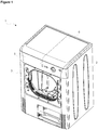
Figure 1 - is the perspective view of a washer/dryer. -
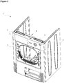
Figure 2 - is the perspective view of a washer/dryer the upper table of which has been removed -
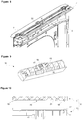
Figure 3 - is the perspective view of a support member. -
Figure 4 - is the exploded top view of the support member. -
Figure 5 - is the perspective view of the support member while the absorber is disposed to the housing. -
Figure 6 - is the detailed front view of the front wall, panel, bracket and support member. -
Figure 7 - is the detailed rear view of the front wall, panel, bracket and support member. -
Figure 8 - is the detailed rear view of the front wall, panel and bracket. -
Figure 9 - is the bottom perspective view of the receptacle. -
Figure 10 - is the front cross-sectional view of the support member. - The elements illustrated in the figures are numbered as follows:
- 1.
- Washer/dryer
- 2.
- Side wall
- 3.
- Front wall
- 4.
- Bracket
- 5.
- Panel
- 6.
- Upper table
- 7.
- Flange
- 8.
- Support member
- 9.
- Absorber
- 10.
- Receptacle
- 11.
- Housing
- 12.
- Retainer
- 13.
- Step
- 14.
- Hole
- 15.
- Detent means
- 16.
- Rib
- 17.
- Stopper
- 18.
- Recess
- 19.
- Entering end
- 20.
- Channel
- 21.
- Ramp
- 22.
- Extension
- 23.
- Opening
- The washer/dryer (1) comprises
- at least two side walls (2) covering the volume from sides wherein the drum, in which the laundry is emplaced, and other machine elements are located,
- a front wall (3) mounted onto the side walls (2) and covering the said volume from front up to a certain height,
- a bracket (4) hung between the side walls (2) from a point near the front edge of the side walls (2),
- a panel (5) covering the space that remains above the front wall (3) from front,
- a flange (7) extending from the upper edge of the panel (5) towards the back,
- an upper table (6) seating onto the upper edges of the side walls (2), onto the bracket (4) and flange (7) and thus, covering the top of the side walls (2) and of the panel (5), and
- at least one support member (8) disposed between the bracket (4) and/or flange (7) and the upper table (6).
- The support member (8) comprises
- at least one absorber (9) which is produced from a material having absorbing feature, and
- a receptacle (10) which is mounted onto the bracket (4) and/or flange (7), wherein the absorber (9) is disposed and which is produced from a rigid material.
- The support member (8) bears against the upper table (6) from below and thus, supports the upper table (6). Thus, on the one hand, the upper table (6) acquires additional resistance by the receptacle (10) and on the other hand, the transfer of the vibration generated during the operation of the washer/dryer (1) to the upper table (6) is reduced by the absorber (9).
- In the preferred embodiment of the present invention, the housing (11) is shaped as a groove which is formed longitudinally on the upper wall of the receptacle (10). The absorber (9) is seated into the housing (11) slidably.
- In this embodiment, the housing (11) comprises at least one retainer (12) which extends from the side edges of the housing (11) towards the inside almost vertically to these edges, and which prevents the absorber (9) disposed into the housing (11) from being detached. The absorber (9) comprises two steps (13) which extend longitudinally at its both sides and which bear against the retainers (12) from below and thus, facilitate the movement during the slidable seating of the absorber (9) into its place. Thus, while the absorber (9) is slidably seated to the housing (11), the step (13) bears against the retainers (12) from below and the absorber (9) is provided to be firmly clasped by the retainers (12).
- In the preferred embodiment of the present invention, the bracket (4) comprises at least one hole (14) which is located almost at its center and which enables it to be mounted onto the receptacle (10). In this embodiment, the receptacle (10) comprises at least one detent means (15) which extends from the lower edge of the receptacle (10) downwards and which is V-shaped such that it will easily enter into the hole (14) but will not be easily detached when pulled back. Thus, the receptacle (10) is provided to be easily locked onto the bracket (4) by snap-fitting and thus, to be fixed thereto.
- In this embodiment, the receptacle (10) comprises a rib (16) which bears against the edges of the hole (14) and provides the receptacle (10) to be fixed in the horizontal direction. Thus, exposure of the support member (8) to the vibrations generated during operation is minimized.
- In an embodiment of the present invention, the receptacle (10) comprises at least one stopper (17) which is located at the base of the housing (11), which provides the absorber (9) to be stopped when it reaches the desired position while being disposed into the housing (11), and which prevents the absorber (9) from being detached by moving in the opposite direction. In this embodiment, the absorber (9) comprises a recess (18) which is located at its base and wherein the stopper (17) fits when the absorber (9) reaches the desired position while being disposed into the housing (11). Thus, when the absorber (9) comes to the desired position in the housing (11), the stopper (17) is provided to be fit into the recess (18) and thus, to be easily fixed therein.
- In this embodiment, the absorber (9) comprises an entering end (19) which provides the absorber (9) to easily leap over the stopper (17) while being disposed in the housing (11), which facilitates the sliding movement and which is suitably inclined for the shape of the stopper (17). Thus, while the absorber (9) is disposed into the housing (11), its movement is prevented from being hindered by the stopper (17).
- In this embodiment, the absorber (9), furthermore, comprises a channel (20) which is located between the entering end (19) and the recess (18), and wherein the stopper (17) moves forward while the absorber (9) is disposed into the housing (11). The absorber (9), furthermore, comprises a ramp (21) which is located at the end of the channel (20) in the disposing direction of the channel (20) into the housing (11), and which is suitably inclined for the shape of the stopper (17). Thus, when the stopper (17) moving forward in the channel (20) arrives at the ramp (21), it easily exits the channel (20) and settles into the recess (18) and thus, fixing is provided.
- In an embodiment of the present invention, the panel (5) comprises at least one extension (22) which provides it to be fixed onto the bracket (4) and which extends from the flange (7) towards the bracket (4). In this embodiment, the receptacle (10) comprises at least one opening (23) which is located at its base and/or at the portion of its side walls that is near the base, wherein the extension (22) fits when the support member (8) is mounted into its place, and thus, which provides the support member (8) to be fixed to the flange (7).
- In the preferred embodiment of the present invention, the receptacle (10) is produced from a plastic material and the absorber (9) is produced from a rubber or Styrofoam material.
- In an embodiment of the present invention, the upper table (6) comprises a depression which is located at its lower surface, at the area the support member (8) contacts, and wherein the support member (8) will at least partially fit.
- In another embodiment of the present invention, the portion of the upper table (6) that is in alignment with the panel (5) is shaped curvedly towards the panel (5). In this embodiment, the support member (8) is disposed behind the said curved portion, to the flat portion of the upper table (6).
- It is to be understood that the present invention is not limited to the embodiments disclosed above and a person skilled in the art can easily introduce different embodiments.
Claims (13)
- A washer/dryer (1) comprising at least two side walls (2) covering the volume from sides wherein the drum, in which the laundry is emplaced, and other machine elements are located, a front wall (3) mounted onto the side walls (2) and covering the said volume from front up to a certain height, a bracket (4) hung between the side walls (2) from a point near the front edge of the side walls (2), a panel (5) covering the space that remains above the front wall (3) from front, a flange (7) extending from the upper edge of the panel (5) towards the back, an upper table (6) seating onto the upper edges of the side walls (2), onto the bracket (4) and flange (7) and thus, covering the top of the side walls (2) and of the panel (5), and at least one support member (8) disposed between the bracket (4) and/or the flange (7) and the upper table (6), wherein the support member (8) has at least one absorber (9) which is produced from a material having absorbing feature, characterized in that- the support member (8) comprises a receptacle (10) having a housing (11) the receptacle (10) being mounted onto the bracket (4) and/or the flange (7), the absorber (9) being disposed in the housing (11) of the receptacle (10) and the receptacle (10) being produced from a rigid material, and- the support member (8) bears against the upper table (6) from below and thus, supports the upper table (6).
- A washer/dryer (1) as in Claim 1 , characterized by the housing (11) that is shaped as a groove which is formed longitudinally on the upper wall of the receptacle (10), and by the absorber (9) that is seated into the housing (11) slidably.
- A washer/dryer (1) as in Claim 1 or 2, characterized by the housing (11) that comprises at least one retainer (12) which extends from the side edges of the housing (11) towards the inside almost vertically to these edges, and which prevents the absorber (9) disposed into the housing (11) from being detached, and by the absorber (9) that comprises two steps (13) which are formed longitudinally at its both sides and which bear against the retainers (12) from below and thus, facilitate the movement during the slidable seating of the absorber (9) into its place.
- A washer/dryer (1) as in any one of the above Claims, characterized by the bracket (4) that comprises at least one hole (14) which is located almost at its center and which enables it to be mounted onto the receptacle (10), and by the receptacle (10) that comprises at least one detent means (15) which extends from the lower edge of the receptacle (10) downwards and which is V-shaped such that it will easily enter into the hole (14) but will not be easily detached when pulled back.
- A washer/dryer (1) as in Claim 4, characterized by the receptacle (10) that comprises at least one rib (16) which bears against the edges of the hole (14) and provides the receptacle (10) to be fixed in the horizontal direction.
- A washer/dryer (1) as in any one of the above Claims, characterized by the receptacle (10) that comprises at least one stopper (17) which is located at the base of the housing (11) and which provides the absorber (9) to be stopped in the housing (11) at the desired position, and by the absorber (9) that comprises a recess (18) wherein the stopper (17) fits when the absorber (9) reaches the desired position while being disposed into the housing (11), and which is located at the base of the absorber (9).
- A washer/dryer (1) as in Claim 6, characterized by the absorber (9) that comprises an entering end (19) which provides the absorber (9) to easily leap over the stopper (17) while being disposed into the housing (11), which facilitates the sliding movement and which is suitably inclined for the shape of the stopper (17).
- A washer/dryer (1) as in Claim 6 or 7, characterized by the absorber (9) that comprises a channel (20) which is located between the entering end (19) and the recess (18), and wherein the stopper (17) moves forward while the absorber (9) is disposed into the housing (11).
- A washer/dryer (1) as in Claim 8, characterized by the absorber (9) that comprises a ramp (21) which is located at the end of the absorber (9) in the disposing direction of the absorber (9) into the housing (11), and which is suitably inclined for the shape of the stopper (17).
- A washer/dryer (1) as in any one of the above Claims, characterized by the panel (5) that comprises at least one extension (22) which provides it to be fixed onto the bracket (4) and which extends from the flange (7) towards the bracket (4), and by the receptacle (10) that comprises at least one opening (23) which is located at its base and/or at the portion of its side walls that is near the base, wherein the extension (22) fits when the support member (8) is mounted into its place, and thus, which provides the support member (8) to be fixed to the flange (7).
- A washer/dryer (1) as in any one of the above Claims, characterized by the upper table (6) that comprises a depression which is located at its lower surface, at the area the support member (8) contacts, and wherein the support member (8) will at least partially fit.
- A washer/dryer (1) as in any one of the above Claims, characterized by the upper table (6), wherein its portion that is in alignment with the panel (5) is shaped curvedly towards the panel (5), and by the support member (8) that is disposed behind the said curved portion, to the flat portion of the upper table (6).
- A washer/dryer (1) as in any one of the above Claims, characterized by the receptacle (10) from a plastic material and by the absorber (9) from a rubber or Styrofoam material.
Applications Claiming Priority (2)
| Application Number | Priority Date | Filing Date | Title |
|---|---|---|---|
| TR200808106 | 2008-10-27 | ||
| PCT/EP2009/063810 WO2010049330A1 (en) | 2008-10-27 | 2009-10-21 | A washer/dryer |
Publications (2)
| Publication Number | Publication Date |
|---|---|
| EP2350377A1 EP2350377A1 (en) | 2011-08-03 |
| EP2350377B1 true EP2350377B1 (en) | 2017-01-11 |
Family
ID=41567248
Family Applications (1)
| Application Number | Title | Priority Date | Filing Date |
|---|---|---|---|
| EP09741287.8A Active EP2350377B1 (en) | 2008-10-27 | 2009-10-21 | A washer/dryer |
Country Status (2)
| Country | Link |
|---|---|
| EP (1) | EP2350377B1 (en) |
| WO (1) | WO2010049330A1 (en) |
Cited By (1)
| Publication number | Priority date | Publication date | Assignee | Title |
|---|---|---|---|---|
| EP4528010A4 (en) * | 2022-06-16 | 2025-08-27 | Lg Electronics Inc | LAUNDRY TREATMENT DEVICE |
Families Citing this family (2)
| Publication number | Priority date | Publication date | Assignee | Title |
|---|---|---|---|---|
| US20110186593A1 (en) * | 2008-02-20 | 2011-08-04 | William Howe | Dispensing vessel for clothes dryer |
| EP2889424B1 (en) * | 2013-12-24 | 2016-09-21 | Electrolux Appliances Aktiebolag | Laundry appliance |
Family Cites Families (3)
| Publication number | Priority date | Publication date | Assignee | Title |
|---|---|---|---|---|
| DE19848875A1 (en) * | 1998-10-22 | 2000-04-27 | Bsh Bosch Siemens Hausgeraete | Built-in domestic appliance has hollow ribs to form supports at defined support points in its housing |
| DE10143050A1 (en) * | 2001-09-03 | 2003-03-20 | Bsh Bosch Siemens Hausgeraete | Cover plate for household appliances |
| PL1918446T3 (en) * | 2006-10-31 | 2010-07-30 | Electrolux Home Products Corp Nv | Household appliance |
-
2009
- 2009-10-21 EP EP09741287.8A patent/EP2350377B1/en active Active
- 2009-10-21 WO PCT/EP2009/063810 patent/WO2010049330A1/en not_active Ceased
Non-Patent Citations (1)
| Title |
|---|
| None * |
Cited By (2)
| Publication number | Priority date | Publication date | Assignee | Title |
|---|---|---|---|---|
| EP4528010A4 (en) * | 2022-06-16 | 2025-08-27 | Lg Electronics Inc | LAUNDRY TREATMENT DEVICE |
| AU2023292776B2 (en) * | 2022-06-16 | 2026-04-16 | Lg Electronics Inc. | Laundry treating apparatus |
Also Published As
| Publication number | Publication date |
|---|---|
| WO2010049330A1 (en) | 2010-05-06 |
| EP2350377A1 (en) | 2011-08-03 |
Similar Documents
| Publication | Publication Date | Title |
|---|---|---|
| US6643900B2 (en) | Quick fixing element | |
| EP1621660B1 (en) | Supporter for clothes washing machine and clothes drying apparatus | |
| TWI654953B (en) | Drawer wall, drawer and drawer configuration | |
| KR102082603B1 (en) | Vehicle license plate mount | |
| US8210371B2 (en) | Basket for refrigerator and mounting apparatus for the basket | |
| US8083299B2 (en) | Housing for a front-loading laundry appliance | |
| JP2014512236A (en) | Drawer rail system | |
| AU2006221219B2 (en) | Washing machine | |
| KR20190117656A (en) | Mounting Plate Assembly for Switchgear Cabinet | |
| KR102184008B1 (en) | License plate holder with clip formed in one piece | |
| JP2011063158A (en) | Mounting structure of carrier plate and window glass, and window regulator using the same | |
| EP2350377A1 (en) | A washer/dryer | |
| EP2638200B1 (en) | A washer/dryer wherein ease of assembly is provided | |
| KR100820062B1 (en) | Heater mounting device of drum washing machine | |
| EP2889424B1 (en) | Laundry appliance | |
| EP2764307B1 (en) | Shelf suitable for use on a cooling device door | |
| KR20080036821A (en) | Storage box mounting structure for refrigerator | |
| KR101122071B1 (en) | drum type washing machine | |
| KR102447236B1 (en) | Vehicle license plate fastening device | |
| KR102265701B1 (en) | Hook assembly with trim | |
| KR20130029159A (en) | Headlining assembly for sunroof | |
| KR101236079B1 (en) | variable structure for guiding the movement thereof | |
| RU2363787C2 (en) | Washing machine | |
| KR102257777B1 (en) | Hook assembly with trim | |
| KR20110126423A (en) | Cover opening prevention device of car tray |
Legal Events
| Date | Code | Title | Description |
|---|---|---|---|
| PUAI | Public reference made under article 153(3) epc to a published international application that has entered the european phase |
Free format text: ORIGINAL CODE: 0009012 |
|
| 17P | Request for examination filed |
Effective date: 20110421 |
|
| AK | Designated contracting states |
Kind code of ref document: A1 Designated state(s): AT BE BG CH CY CZ DE DK EE ES FI FR GB GR HR HU IE IS IT LI LT LU LV MC MK MT NL NO PL PT RO SE SI SK SM TR |
|
| RIN1 | Information on inventor provided before grant (corrected) |
Inventor name: CETINKAYA, ERTAN Inventor name: GULBAY, UMIT Inventor name: OZYAKA, ISIK Inventor name: KASAPOGLU, SERKAN |
|
| RIN1 | Information on inventor provided before grant (corrected) |
Inventor name: CETINKAYA, ERTAN Inventor name: OZYAKA, ISIK Inventor name: GULBAY, UMIT Inventor name: KASAPOGLU, SERKAN |
|
| DAX | Request for extension of the european patent (deleted) | ||
| GRAP | Despatch of communication of intention to grant a patent |
Free format text: ORIGINAL CODE: EPIDOSNIGR1 |
|
| INTG | Intention to grant announced |
Effective date: 20160919 |
|
| GRAS | Grant fee paid |
Free format text: ORIGINAL CODE: EPIDOSNIGR3 |
|
| GRAA | (expected) grant |
Free format text: ORIGINAL CODE: 0009210 |
|
| AK | Designated contracting states |
Kind code of ref document: B1 Designated state(s): AT BE BG CH CY CZ DE DK EE ES FI FR GB GR HR HU IE IS IT LI LT LU LV MC MK MT NL NO PL PT RO SE SI SK SM TR |
|
| REG | Reference to a national code |
Ref country code: GB Ref legal event code: FG4D |
|
| REG | Reference to a national code |
Ref country code: CH Ref legal event code: EP |
|
| REG | Reference to a national code |
Ref country code: AT Ref legal event code: REF Ref document number: 861388 Country of ref document: AT Kind code of ref document: T Effective date: 20170115 |
|
| REG | Reference to a national code |
Ref country code: IE Ref legal event code: FG4D |
|
| REG | Reference to a national code |
Ref country code: DE Ref legal event code: R096 Ref document number: 602009043703 Country of ref document: DE |
|
| REG | Reference to a national code |
Ref country code: LT Ref legal event code: MG4D |
|
| REG | Reference to a national code |
Ref country code: NL Ref legal event code: MP Effective date: 20170111 |
|
| REG | Reference to a national code |
Ref country code: AT Ref legal event code: MK05 Ref document number: 861388 Country of ref document: AT Kind code of ref document: T Effective date: 20170111 |
|
| PG25 | Lapsed in a contracting state [announced via postgrant information from national office to epo] |
Ref country code: NL Free format text: LAPSE BECAUSE OF FAILURE TO SUBMIT A TRANSLATION OF THE DESCRIPTION OR TO PAY THE FEE WITHIN THE PRESCRIBED TIME-LIMIT Effective date: 20170111 |
|
| PG25 | Lapsed in a contracting state [announced via postgrant information from national office to epo] |
Ref country code: LT Free format text: LAPSE BECAUSE OF FAILURE TO SUBMIT A TRANSLATION OF THE DESCRIPTION OR TO PAY THE FEE WITHIN THE PRESCRIBED TIME-LIMIT Effective date: 20170111 Ref country code: NO Free format text: LAPSE BECAUSE OF FAILURE TO SUBMIT A TRANSLATION OF THE DESCRIPTION OR TO PAY THE FEE WITHIN THE PRESCRIBED TIME-LIMIT Effective date: 20170411 Ref country code: FI Free format text: LAPSE BECAUSE OF FAILURE TO SUBMIT A TRANSLATION OF THE DESCRIPTION OR TO PAY THE FEE WITHIN THE PRESCRIBED TIME-LIMIT Effective date: 20170111 Ref country code: GR Free format text: LAPSE BECAUSE OF FAILURE TO SUBMIT A TRANSLATION OF THE DESCRIPTION OR TO PAY THE FEE WITHIN THE PRESCRIBED TIME-LIMIT Effective date: 20170412 Ref country code: IS Free format text: LAPSE BECAUSE OF FAILURE TO SUBMIT A TRANSLATION OF THE DESCRIPTION OR TO PAY THE FEE WITHIN THE PRESCRIBED TIME-LIMIT Effective date: 20170511 Ref country code: HR Free format text: LAPSE BECAUSE OF FAILURE TO SUBMIT A TRANSLATION OF THE DESCRIPTION OR TO PAY THE FEE WITHIN THE PRESCRIBED TIME-LIMIT Effective date: 20170111 |
|
| PG25 | Lapsed in a contracting state [announced via postgrant information from national office to epo] |
Ref country code: PL Free format text: LAPSE BECAUSE OF FAILURE TO SUBMIT A TRANSLATION OF THE DESCRIPTION OR TO PAY THE FEE WITHIN THE PRESCRIBED TIME-LIMIT Effective date: 20170111 Ref country code: BG Free format text: LAPSE BECAUSE OF FAILURE TO SUBMIT A TRANSLATION OF THE DESCRIPTION OR TO PAY THE FEE WITHIN THE PRESCRIBED TIME-LIMIT Effective date: 20170411 Ref country code: AT Free format text: LAPSE BECAUSE OF FAILURE TO SUBMIT A TRANSLATION OF THE DESCRIPTION OR TO PAY THE FEE WITHIN THE PRESCRIBED TIME-LIMIT Effective date: 20170111 Ref country code: LV Free format text: LAPSE BECAUSE OF FAILURE TO SUBMIT A TRANSLATION OF THE DESCRIPTION OR TO PAY THE FEE WITHIN THE PRESCRIBED TIME-LIMIT Effective date: 20170111 Ref country code: ES Free format text: LAPSE BECAUSE OF FAILURE TO SUBMIT A TRANSLATION OF THE DESCRIPTION OR TO PAY THE FEE WITHIN THE PRESCRIBED TIME-LIMIT Effective date: 20170111 Ref country code: PT Free format text: LAPSE BECAUSE OF FAILURE TO SUBMIT A TRANSLATION OF THE DESCRIPTION OR TO PAY THE FEE WITHIN THE PRESCRIBED TIME-LIMIT Effective date: 20170511 Ref country code: SE Free format text: LAPSE BECAUSE OF FAILURE TO SUBMIT A TRANSLATION OF THE DESCRIPTION OR TO PAY THE FEE WITHIN THE PRESCRIBED TIME-LIMIT Effective date: 20170111 |
|
| REG | Reference to a national code |
Ref country code: DE Ref legal event code: R097 Ref document number: 602009043703 Country of ref document: DE |
|
| PG25 | Lapsed in a contracting state [announced via postgrant information from national office to epo] |
Ref country code: CZ Free format text: LAPSE BECAUSE OF FAILURE TO SUBMIT A TRANSLATION OF THE DESCRIPTION OR TO PAY THE FEE WITHIN THE PRESCRIBED TIME-LIMIT Effective date: 20170111 Ref country code: RO Free format text: LAPSE BECAUSE OF FAILURE TO SUBMIT A TRANSLATION OF THE DESCRIPTION OR TO PAY THE FEE WITHIN THE PRESCRIBED TIME-LIMIT Effective date: 20170111 Ref country code: SK Free format text: LAPSE BECAUSE OF FAILURE TO SUBMIT A TRANSLATION OF THE DESCRIPTION OR TO PAY THE FEE WITHIN THE PRESCRIBED TIME-LIMIT Effective date: 20170111 Ref country code: EE Free format text: LAPSE BECAUSE OF FAILURE TO SUBMIT A TRANSLATION OF THE DESCRIPTION OR TO PAY THE FEE WITHIN THE PRESCRIBED TIME-LIMIT Effective date: 20170111 Ref country code: IT Free format text: LAPSE BECAUSE OF FAILURE TO SUBMIT A TRANSLATION OF THE DESCRIPTION OR TO PAY THE FEE WITHIN THE PRESCRIBED TIME-LIMIT Effective date: 20170111 |
|
| PLBE | No opposition filed within time limit |
Free format text: ORIGINAL CODE: 0009261 |
|
| STAA | Information on the status of an ep patent application or granted ep patent |
Free format text: STATUS: NO OPPOSITION FILED WITHIN TIME LIMIT |
|
| PG25 | Lapsed in a contracting state [announced via postgrant information from national office to epo] |
Ref country code: SM Free format text: LAPSE BECAUSE OF FAILURE TO SUBMIT A TRANSLATION OF THE DESCRIPTION OR TO PAY THE FEE WITHIN THE PRESCRIBED TIME-LIMIT Effective date: 20170111 Ref country code: DK Free format text: LAPSE BECAUSE OF FAILURE TO SUBMIT A TRANSLATION OF THE DESCRIPTION OR TO PAY THE FEE WITHIN THE PRESCRIBED TIME-LIMIT Effective date: 20170111 |
|
| 26N | No opposition filed |
Effective date: 20171012 |
|
| PG25 | Lapsed in a contracting state [announced via postgrant information from national office to epo] |
Ref country code: SI Free format text: LAPSE BECAUSE OF FAILURE TO SUBMIT A TRANSLATION OF THE DESCRIPTION OR TO PAY THE FEE WITHIN THE PRESCRIBED TIME-LIMIT Effective date: 20170111 |
|
| REG | Reference to a national code |
Ref country code: DE Ref legal event code: R119 Ref document number: 602009043703 Country of ref document: DE |
|
| PG25 | Lapsed in a contracting state [announced via postgrant information from national office to epo] |
Ref country code: MC Free format text: LAPSE BECAUSE OF FAILURE TO SUBMIT A TRANSLATION OF THE DESCRIPTION OR TO PAY THE FEE WITHIN THE PRESCRIBED TIME-LIMIT Effective date: 20170111 |
|
| REG | Reference to a national code |
Ref country code: CH Ref legal event code: PL |
|
| REG | Reference to a national code |
Ref country code: IE Ref legal event code: MM4A |
|
| REG | Reference to a national code |
Ref country code: FR Ref legal event code: ST Effective date: 20180629 |
|
| PG25 | Lapsed in a contracting state [announced via postgrant information from national office to epo] |
Ref country code: LU Free format text: LAPSE BECAUSE OF NON-PAYMENT OF DUE FEES Effective date: 20171021 Ref country code: DE Free format text: LAPSE BECAUSE OF NON-PAYMENT OF DUE FEES Effective date: 20180501 Ref country code: CH Free format text: LAPSE BECAUSE OF NON-PAYMENT OF DUE FEES Effective date: 20171031 Ref country code: LI Free format text: LAPSE BECAUSE OF NON-PAYMENT OF DUE FEES Effective date: 20171031 |
|
| REG | Reference to a national code |
Ref country code: BE Ref legal event code: MM Effective date: 20171031 |
|
| PG25 | Lapsed in a contracting state [announced via postgrant information from national office to epo] |
Ref country code: FR Free format text: LAPSE BECAUSE OF NON-PAYMENT OF DUE FEES Effective date: 20171031 Ref country code: BE Free format text: LAPSE BECAUSE OF NON-PAYMENT OF DUE FEES Effective date: 20171031 |
|
| PG25 | Lapsed in a contracting state [announced via postgrant information from national office to epo] |
Ref country code: MT Free format text: LAPSE BECAUSE OF NON-PAYMENT OF DUE FEES Effective date: 20171021 |
|
| PG25 | Lapsed in a contracting state [announced via postgrant information from national office to epo] |
Ref country code: IE Free format text: LAPSE BECAUSE OF NON-PAYMENT OF DUE FEES Effective date: 20171021 |
|
| PG25 | Lapsed in a contracting state [announced via postgrant information from national office to epo] |
Ref country code: HU Free format text: LAPSE BECAUSE OF FAILURE TO SUBMIT A TRANSLATION OF THE DESCRIPTION OR TO PAY THE FEE WITHIN THE PRESCRIBED TIME-LIMIT; INVALID AB INITIO Effective date: 20091021 |
|
| PG25 | Lapsed in a contracting state [announced via postgrant information from national office to epo] |
Ref country code: CY Free format text: LAPSE BECAUSE OF NON-PAYMENT OF DUE FEES Effective date: 20170111 |
|
| PG25 | Lapsed in a contracting state [announced via postgrant information from national office to epo] |
Ref country code: MK Free format text: LAPSE BECAUSE OF FAILURE TO SUBMIT A TRANSLATION OF THE DESCRIPTION OR TO PAY THE FEE WITHIN THE PRESCRIBED TIME-LIMIT Effective date: 20170111 |
|
| PGFP | Annual fee paid to national office [announced via postgrant information from national office to epo] |
Ref country code: GB Payment date: 20211022 Year of fee payment: 13 |
|
| GBPC | Gb: european patent ceased through non-payment of renewal fee |
Effective date: 20221021 |
|
| PG25 | Lapsed in a contracting state [announced via postgrant information from national office to epo] |
Ref country code: GB Free format text: LAPSE BECAUSE OF NON-PAYMENT OF DUE FEES Effective date: 20221021 |
|
| PGFP | Annual fee paid to national office [announced via postgrant information from national office to epo] |
Ref country code: TR Payment date: 20251015 Year of fee payment: 17 |