EP2348694A2 - Communication method and system - Google Patents
Communication method and system Download PDFInfo
- Publication number
- EP2348694A2 EP2348694A2 EP11250069A EP11250069A EP2348694A2 EP 2348694 A2 EP2348694 A2 EP 2348694A2 EP 11250069 A EP11250069 A EP 11250069A EP 11250069 A EP11250069 A EP 11250069A EP 2348694 A2 EP2348694 A2 EP 2348694A2
- Authority
- EP
- European Patent Office
- Prior art keywords
- button
- computing device
- software
- communication
- user
- Prior art date
- Legal status (The legal status is an assumption and is not a legal conclusion. Google has not performed a legal analysis and makes no representation as to the accuracy of the status listed.)
- Granted
Links
- 238000004891 communication Methods 0.000 title claims abstract description 79
- 238000000034 method Methods 0.000 title claims description 37
- 238000012546 transfer Methods 0.000 claims description 6
- 230000000694 effects Effects 0.000 claims description 2
- 230000004044 response Effects 0.000 abstract description 8
- 238000007726 management method Methods 0.000 description 7
- 238000010586 diagram Methods 0.000 description 6
- 230000009471 action Effects 0.000 description 4
- 230000008859 change Effects 0.000 description 4
- 230000008901 benefit Effects 0.000 description 3
- 230000000977 initiatory effect Effects 0.000 description 3
- 230000003068 static effect Effects 0.000 description 3
- 238000013459 approach Methods 0.000 description 2
- 230000005540 biological transmission Effects 0.000 description 2
- 230000006855 networking Effects 0.000 description 2
- 230000008569 process Effects 0.000 description 2
- 230000004913 activation Effects 0.000 description 1
- 238000007792 addition Methods 0.000 description 1
- 230000001413 cellular effect Effects 0.000 description 1
- 238000012986 modification Methods 0.000 description 1
- 230000004048 modification Effects 0.000 description 1
- 230000008520 organization Effects 0.000 description 1
- 230000035755 proliferation Effects 0.000 description 1
- 230000000717 retained effect Effects 0.000 description 1
- 238000006467 substitution reaction Methods 0.000 description 1
Images


Classifications
-
- H—ELECTRICITY
- H04—ELECTRIC COMMUNICATION TECHNIQUE
- H04M—TELEPHONIC COMMUNICATION
- H04M1/00—Substation equipment, e.g. for use by subscribers
- H04M1/247—Telephone sets including user guidance or feature selection means facilitating their use
- H04M1/2471—Configurable and interactive telephone terminals with subscriber controlled features modifications, e.g. with ADSI capability [Analog Display Services Interface]
- H04M1/2472—Configurable and interactive telephone terminals with subscriber controlled features modifications, e.g. with ADSI capability [Analog Display Services Interface] with programmable function keys
-
- H—ELECTRICITY
- H04—ELECTRIC COMMUNICATION TECHNIQUE
- H04M—TELEPHONIC COMMUNICATION
- H04M3/00—Automatic or semi-automatic exchanges
- H04M3/42—Systems providing special services or facilities to subscribers
- H04M3/42136—Administration or customisation of services
- H04M3/42178—Administration or customisation of services by downloading data to substation equipment
-
- H—ELECTRICITY
- H04—ELECTRIC COMMUNICATION TECHNIQUE
- H04M—TELEPHONIC COMMUNICATION
- H04M7/00—Arrangements for interconnection between switching centres
- H04M7/0024—Services and arrangements where telephone services are combined with data services
- H04M7/003—Click to dial services
-
- H—ELECTRICITY
- H04—ELECTRIC COMMUNICATION TECHNIQUE
- H04M—TELEPHONIC COMMUNICATION
- H04M7/00—Arrangements for interconnection between switching centres
- H04M7/0024—Services and arrangements where telephone services are combined with data services
- H04M7/0042—Services and arrangements where telephone services are combined with data services where the data service is a text-based messaging service
-
- H—ELECTRICITY
- H04—ELECTRIC COMMUNICATION TECHNIQUE
- H04M—TELEPHONIC COMMUNICATION
- H04M1/00—Substation equipment, e.g. for use by subscribers
- H04M1/253—Telephone sets using digital voice transmission
- H04M1/2535—Telephone sets using digital voice transmission adapted for voice communication over an Internet Protocol [IP] network
-
- H—ELECTRICITY
- H04—ELECTRIC COMMUNICATION TECHNIQUE
- H04M—TELEPHONIC COMMUNICATION
- H04M7/00—Arrangements for interconnection between switching centres
- H04M7/0024—Services and arrangements where telephone services are combined with data services
- H04M7/0054—Services and arrangements where telephone services are combined with data services where the data service is an electronic mail service
Definitions
- the present invention relates generally to electronic communication and, more particularly, concerns communications which can be initiated through an externally provided, actuable executable, such as a software button, to control privacy, security and the nature and type of communication service.
- Communications associated with the present invention are provided through the use of a "computing device”, which will be understood to include not only an actual computer, such as a personal computer, but also any kind of intelligent device, such as a personal digital assistant (PDA) or a smart telephone, capable of Internet browsing.
- PDA personal digital assistant
- the device will need to be capable of sensing sound, as through a microphone, and producing sound, as through a speaker or earphone.
- Communication takes place through a network, such as the Internet and, possibly, through the public service telephone network (PSTN).
- PSTN public service telephone network
- a software button is utilized on a computing device to initiate a call. Activation of the button causes a "soft phone" to be downloaded from a server.
- the soft phone is essentially an executable software agent that operates on the computing device to set up a call to only a specified telephone number.
- the software agent causes certain call context information to be embedded which is unique to the actuated software button.
- an online directory similar to a telephone directory but comprised of software buttons, is provided, in which a calling party can select a called party by clicking a software button dedicated to the called party.
- the button provides an identification of the called party, but some or all contact information may be hidden and inaccessible to the calling party.
- a server containing the directory will then cause download of a software agent to the calling party's computing device, which causes the calling party's computing device to establish communication with the called party.
- the called party can maintain privacy, or even complete anonymity.
- buttons are utilized to provide a communication service which is dynamic. That is, the nature or type of service changes based on conditions predefined by the called party and information provided by the calling party. For example, a called party may specify that, during business hours, communication be by telephone to a specific telephone number and outside of business hours, communication be by text message if urgent and e-mail if not urgent.
- the calling party clicks a software button the software agent downloaded to his computing device would then be a soft phone during business hours. Outside of business hours, a software agent would be downloaded to the calling party which would inquire whether the call is urgent and, depending upon the response, would provide a text message agent or an e-mail agent, respectively.
- Fig. 1 is a functional block diagram illustrating the overall service operations for users and subscribers of a Button Directory System embodying the present invention
- Fig. 2 is a functional block diagram illustrating a button directory system embodying the present invention
- Fig. 3 is a flowchart illustrate the service usage steps between a Sender and a Recipient in accordance with an embodiment of the present invention.
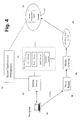
- Fig. 4 is a functional block diagram of an intelligent button service system embodying the present invention.
- Telephone Directory essentially a directory of publicly listed telephone numbers of individuals and businesses (subscribers). Many forms and variations of such directories are available on the Internet, and search services like Google can provide easy and convenient lookup.
- the primary advantage of being listed in the Telephone Directory is its accessibility to the public. Unfortunately, that is also its primary disadvantage, owing to its widespread use for telemarketing, and such.
- Fig. 1 is a functional block diagram illustrating the overall service operations for users and subscribers of a Button Directory System embodying the present invention.
- the service is provided through a website 10 accessible to the general public (e.g. user 12).
- Information on this website is arranged in a manner similar to other directories for individuals and businesses, viewable by categories or by regions, and searchable by key words, and so on.
- Listings are assumed to be supplied and controlled (block 14) by subscribers 16. Unlike a more conventional Telephone Directory is that a contact address for each listing is presented as a user-actuable software button, or some other actuable item, not as an explicit phone number or email address. Actuation of a button by a user 12 causes a software agent to be downloaded to the user's computer, which results in a communication connection with the selected listing subscriber.
- actionable features could include: Calling, email, send SMS (Short Message Service) text message to cell phone or leave a message.
- SMS Short Message Service
- the actual contact addresses are not available to the user seeking the connection (caller).
- a subscriber In configuring a particular communication option, a subscriber obviously has to provide appropriate parameters to use. For example, the subscriber has to specify a phone number for calling, an email address for email, and so on. These parameters are written into a button database 32, available to server 10, and they are hidden from the users. The parameters provided by a subscriber can be changed anytime, and the change does not affect the listing of the buttons. While it is difficult to account for all kinds of privacy issues, it would be advantageous for the service to provide security guards against telemarketing calls and spam email. Many such techniques are well known in the art.
- website 10 might simply transfer user 14 to a button server 18, which would present a menu to the user to select the type of communication desired with the selected subscriber. Upon receiving the user's response, the button server then downloads software to the user, providing the interface for the type of connection he selected.
- website 10 could include a separate button for each type of service available for a subscriber (e.g. telephone, e-mal, SMS), and when the user actuates a button corresponding to a particular service, website 10 transfers him to server 18 and provides server 18 with sufficient information regarding the requested service.
- Server 18 then downloads executable software for the requested service. For example, it might download an e-mail interface linked to the selected subscriber to be run on the user's computing device.
- the communication interface provided by button server 18 interacts with a media server 20, which provides real time communication services for the user's computing device. This can include PSTN or VolP service if the user is communicating by voice.
- Fig. 2 is a functional block diagram illustrating a button directory system embodying the present invention.
- a public user 12 communicates with the system through a directory server 30, which includes the website 10 as a user interface.
- the underlying information supporting the button directory system is maintained in a directory database 32, to which directory server 30 has access.
- the information in the database 32 is managed through a service management interface 34, to which each listing subscriber 16 has access, in order to manage the information in database 32 related to him.
- directory server 30 transfers the user's computing device to button server18, which downloads an executable agent to the user's computing device. That agent creates a communications interface to the user's computing device which communicates only with the selected subscriber, using the service the user selected for the communication.
- a listing subscriber has an interface 28, through which he may manage the communication services available to him. This includes, not only selecting services and to be available, but providing appropriate address and configuration information for each service. If a user's communication is to include media, the communications interface created on his computing device is directed to a media router 40 and, therethrough, to an appropriate media gateway 42. If the communication is a voice communication, the media gateway can direct the communication to the PSTN or a VolP server 44, as appropriate.
- the Button Server may download a web (voice or video) phone to a browser on the user's computing device, allowing the subsequent media connection to be made to the Media Router.
- the call can then be routed as shown in Fig. 2 through the PSTN or Internet.
- additional media-type servers such as a voicemail server may have to be used.
- media players and or other web phone or media interface software already on the user's computing device may be invoked.
- the disclosed system architecture can support any available anti-spam technique.
- a so-called Captcha can be implemented in the email service to ensure that the email message is generated by a human rather than a machine.
- a common type of Captcha requires the user to type in alphanumeric digits from a distorted image appearing on the screen.
- the calling feature can require the user to provide a phone number for call back, with the call being completed by bridging a call from the system to this call-back number and another call to the listing's number.
- the listings are essentially virtual addresses for a subscriber, whose name (or pseudonym) is disclosed in public, but his real address information (and possibly his real identity) is hidden. More importantly, control of how a listed subscriber is reached is retained by the subscriber himself. This will permit online transactions to move in new directions. For example, it is relatively "safe” for individuals to put “want ads” in their public listings in order to solicit potential offerings from others. With the use of a proper matching-based application, this approach can facilitate buying and selling in a broad sense. Similarly, by giving permission for the website to use their preferences or parts of their profile, listing members of the service could allow certain advertising messages to be sent to their designated (internal) mail box. If organized properly, this approach helps merchants to direct their marketing materials to interested parties only and thus reduces the wastefulness of junk mail overall.
- the disclosed service can post any information for individuals and businesses in its listings without much constraint.
- an old-fashion telephone directory listing typically only provides name, address and home phone number.
- a service in accordance with the present invention can include links to a personal website, a personal profile or any personal posting desired by the individual.
- a distinctive aspect in such listings is that the listing owner controls the privacy and access policy regarding such information.
- the goal is obviously to make the contact information readily known and available to the public.
- Making a communication connection with another party typically means making a phone call (PSTN, cell or VoIP), sending an SMS (Short Message Service) message on a cell phone, sending an Instant Message (IM) on a computer or sending an email.
- PSTN public switched telephone network
- SMS Short Message Service
- IM Instant Message
- a "Caller” who initiates the call or the connection (real-time or messaging) with his telephone or computing device, makes a clear choice of the connection or service type to be used (i.e., phone, email, IM or SMS).
- the resulting connection is made to the appropriate receiving device (phone, computer, email box, etc.) used by the "Receiver", who is the intended recipient of the call.
- connections will be referred to as "static", because the underlying Caller or Receiver behavior and the underlying technical operations involving transmission, routing and reception of data are essentially predetermined when the Caller makes the call.
- a Caller's initiation of a phone call results in a phone call connection, which does not unexpectedly change to an email session.
- the call itself and not the known technique of changing the service delivery of data to the Receiver after the call or connection is completed, such as by using an answering machine, turning a recorded message into an email, or forwarding a message to SMS.
- These post-connection delivery actions do not change the static nature of the call itself.
- dynamic routing of data to different physical destinations such as call forwarding or call transfer does not alter the static nature of the call or connection.
- a call or connection will be deemed “dynamic” or “intelligent” if the connection resulting from a call initiation can vary in dependence upon instantaneous states derived from inputs and/or parameters related to the Caller and/or Receiver.
- a software button labeled "Connect to Joe Doe” is sent to a Recipient allowing the Recipient to make a call to Joe Doe, the "Sender” (of the button).
- this Button is actuated (e.g. clicked) at different times, the resulting connection may be completely different.
- the connection may be a phone call at one time and an SMS session at another time, generally not determined by the Caller's (the button "Recipient's") action alone.
- an intelligent service is provided, based on the use of dynamic software buttons.
- the service is "intelligent” or “dynamic” because the call or connection to be made can be different, depending on the information about the operating conditions or “states” predefined by the Receiver, Caller input, and the context of the call.
- buttons in use are considered dynamic, because they are not dedicated to a particular service type, such as calling or e-mailing.
- the service created upon clicking on a dynamic button may vary depending on operating parameters and the inputs and parameters provided by the Caller and the Sender. These inputs and parameters together are called the state of the button. Thus, clicking on a button at different times may lead to different outcomes, according to the instantaneous state of the button.
- each dynamic button uniquely defines a Sender (call Receiver) and a Recipient (call initiating Caller).
- a button is sent from a Sender to a Recipient.
- the Recipient When clicking on a button, the Recipient is attempting to initiate a call to the Sender.
- the (button) Recipient is the Caller (making the call)
- the (button) Sender is the Receiver (of the call).
- Recipient and Sender are associated with the button operation
- Caller and Receiver are associated with the call session.
- Fig. 3 is a flowchart illustrating the service usage steps between a Sender and a Recipient in accordance with an embodiment of the present invention.
- the process begins at block 50 when the Sender sends a software button to a Recipient's computing device (for example, by email).
- a Recipient's computing device for example, by email
- the Recipient actuates the received button by clicking on it (block 52)
- the Recipient actuates the received button by clicking on it (block 52)
- No preinstalled software is required on the Recipient's computing device other than a standard Internet browser.
- the Recipient After the Recipient initially clicks the button, he may receive a termination message closing the session (block 54) if the connection cannot be established. Otherwise, there are two possible outcomes of the Recipient's action, at block 56: (1) A particular service connection is initiated to reach the Sender, or (2) a message window is opened on the Recipient's computing device prompting the Recipient for inputs. In the event of outcome (1), control is transferred to block 58, where an appropriate executable agent is downloaded to the Recipient's browser to support the particular service being initiated. In the event of outcome (2), a user interface is downloaded to the Recipient's computing device for the Recipient to provide the input information to determine the connection type (block 60). Following receipt of the Recipient's input, control is transferred to block 58, where an appropriate executable agent is downloaded to the Recipient's browser to support the particular service being initiated. The process ends at block 58.
- the Recipient is not determining the type of connection to be made but is providing information that will be used to determine the type of connection, based on pre-established considerations. For example, the Recipient might be asked whether the call is urgent or to describe the subject matter. Based on the Sender's prior action, for urgent, matters or certain subject matter a telephone connection might be established, while for non-urgent matters or other subject matter a busy signal may be posted and an e-mail connection might be established. Similarly, during certain hours a busy signal might be posted and an SMS connection might be established instead of a telephone connection.
- the idea is that some Recipient inputs may be used by the system to decide what to do with the call.
- the logic for call handling is determined by the states preset by the Sender.
- Fig. 4 is a functional block diagram of an intelligent button service system embodying the present invention.
- a button received by a Recipient's computing device 13 is essentially a website link to a Button Server 70.
- the button is also encoded with a unique button identification (BID).
- BID button identification
- the Recipient's web browser opens a link directed to the Button Server as equivalent to a call request.
- Button Server 70 a lookup is done immediately in a button database accessible to Button Server 70 (in Button Database and Management Unit 72) using the BID, to retrieve the instantaneous state of the Button.
- the state of the Button here refers to parameters preset by the Sender for various options for responding to a call request. These parameters may be changed by the Sender at will by accessing Database and Management Unit 72. For instance, a Sender may set an option to post a particular message and to respond with an SMS connection. In that case, an agent will be downloaded from the Button Server to the Recipient's computing device to display the Sender's message and also a user interface for the Recipient to input a message to be sent as SMS to the Sender. At another time, a click on the same Button may result in a direct phone call to the Sender, assuming the Sender has chosen to set the Button state to respond with a voice connection. As mentioned earlier, some options may also request additional inputs from the Recipient before a particular connection is chosen, such as to whether the call is urgent or not.
- the service servers 74 shown in Fig. 4 are used to provide various services or connections.
- the Sender's computing device 17 has access to servers 74, in order to set up various services.
- the Sender needs to provide telephone numbers and e-mail addresses to service servers 74.
- real-time services e.g., voice or video
- media packets are transmitted from the Recipient's computing device 13 to a Media Router 40 and media gateway 42 for handling instead of going through the Button Server.
- non-connection oriented services possible in this system, e.g. Sender Location or Presence. These latter services, however, are not related to the concept of dynamic buttons.
- an interface allows a sender to do button management, providing a convenient means for a Sender alter parameters associated with the button. This is accomplished by installing a Button Management Agent 76, or a custom application program (a software agent) on the Sender's computing device 17.
- This agent contains a directory of the Sender's buttons and provides easy management menus for the Sender to update and modify state parameters for the buttons. It should be appreciated that all buttons need not have the same state, and there are many ways to devise convenient control and setting of the state parameters.
- the Sender's computing device 17 is a smart cell phone equipped with a GPS (Global Positioning System), then location information can be used to drive some of the options. For example, all calls could be blocked when the Sender is at home.
- GPS Global Positioning System
- the button parameters may also vary by individual using the button to do the contact, or for other purposes.
- the button may initiate one form of contact if the button user is a specific one or more people, and another form of contact for other users.
- the parameters may also change by time, so that at certain times of the day, an email is generated, and at other times of the day, a phone call is made. Combinations of these parameters are also contemplated.
- one of the sender specific parameters may be kept confidential and one or more may be sent to the user, based upon the identity of the user, or any of the other parameters.
- certain users may be given an option to themselves select or assist in selecting the contact methodology. For example, user category A is given an option to activate the button, and the sender is emailed.
- User group B is given the phone number of the sender.
- User group C is given a choice to call or email the sender, at that user's option, but is not given the email address or the phone number of the sender.
- Users in group D may be given the phone number and email address of the sender, and told to contact the sender by whatever means they deem appropriate.
- User group E may be blocked from any contact whatsoever..
- a method for establishing a communication connection between a calling computing device connected to a network and a second device comprising the steps of:
- Clause 2 The method of clause 1 wherein the software button includes a public identification of the second device and is provided on a server connected to the network, along with at least one additional actuable software button which is associated with a third device, contains a public identification of the third device, the additional software button being constructed so that upon its actuation, an additional software agent is downloaded to the calling computing device, said additional software agent containing additional control information including an additional address, not derived from or accessible to the user of the calling computing device, for contacting the third device.
- Clause 4 The method of Clause 2, further comprising the user of the second device or the user of the third device being provided access to input and modify information on the server related to their respective devices, the information affecting the content of the control information.
- Clause 5 The method of Clause 1 wherein the second device is one of a plurality of devices used by a called party which utilize different types of communication connections, the information provided from the user of the second device including instructions on which of the plurality of devices to use for communication in predefined operating states, the information for controlling the type of connection being determined by the instantaneous operating state, the executable agent being constructed to configure the calling computing device so as to utilize a communication interface type consistent with the instantaneous operating state, whereby communication is effected with the device selected by the called party for the instantaneous operating state.
- Clause 6 The method of Clause 5 wherein the operating states include one of: (i) the urgency of the call; (ii) the subject matter of the call; (iii) the time or day of the call; (iv) the location of the called party; and (v)the context of the call.
- Clause 7 The method of Clause 5 wherein the types of communication connections include at least two of: (i) telephone; (ii) SMS; and (iii) e-mail.
- Clause 8 The method of Clause 5 wherein the software button is sent to the calling computing device from a button database, the called party being provided access to input and modify information on the database related to defining operating states to be associated, respectively, with each of the plurality of devices.
- a button directory system for establishing communications comprising:
- Clause 10 The system of Clause 9 wherein the directory server is publicly accessible.
- Clause 12 The system of Clause 9, further comprising a management unit providing callable parties access to input and modify their private information in the database.
- a method for providing a button directory system for establishing communications comprising:
- Clause 14 The method of Clause 13 wherein the interface is publicly accessible.
- Clause 15 The method of Clause 13, further comprising providing a listed party access to the database, permitting him to input and edit his private information.
- Clause 16 The method of Clause 13 wherein two buttons in the interface correspond to two different types of connections to the same listed party.
- a system for establishing a communication connection between a calling computing device connected to a network and a second device comprising:
- Clause 18 The system of Clause 17 wherein the software button includes a public identification of the second device and further comprising a server connected to the network on which the software button is available, along with at least one additional actuable software button which is associated with a third device, contains a public identification of the third device, the additional software button being constructed so that upon its actuation, an additional software agent is downloaded from the generator to the calling computing device, said additional software agent containing additional control information including an additional address, accessible to the user of the calling computing device, for contacting the third device.
- Clause 19 The system of Clause 18 wherein the server is publicly accessible.
- Clause 20 The system of Clause 18, further comprising means providing access to the user of the second device or the user of the third device to input and modify information on the server related to their respective devices, the information affecting the content of the control information.
- Clause 21 The system of Clause 17 wherein the second device is one of a plurality of devices used by a called party which utilize different types of communication connections, the information provided from the user of the second device including instructions on which of the plurality of devices to use for communication in predefined operating states, the system further comprising means for determining the instantaneous operating state, the executable agent from the generator being constructed to configure the calling computing device so as to utilize a communication interface type consistent with the instantaneous operating state, whereby communication is effected with the device selected by the called party for the instantaneous operating state.
- Clause 22 The system of Clause 21 wherein the operating states include one of: (i) the urgency of the call; (ii) the subject matter of the call; (iii) the time or day of the call; (iv) the location of the called party; and (v)the context of the call.
- Clause 23 The system of Clause 21 wherein the types of communication connections include at least two of: (i) telephone; (ii) SMS; and (iii) e-mail.
- Clause 24 The system of Clause 21 further comprising a button database containing information provided to the generator, the called party being provided access to input and modify information on the button database related to defining operating states to be associated, respectively, with each of the plurality of devices.
- a method for providing dynamic communication between a calling computing device and a called party accessible via a plurality of different types of connections comprising:
- Clause 26 The method of Clause 25 wherein the step of determining the operating state requires information from the calling computing device, said step of determining the operating state being preceded by:
- Clause 27 The method of Clause 25 wherein the database contains information regarding different types of connections available to an additional called party, in which the additional called party has specified operating states in which each type of connection is to be used, the method being used to create a dynamic communications with the additional called party, by:
- a system for providing dynamic communication between a calling computing device and a called party accessible via a plurality of types of connections comprising:
- Clause 29 The system of Clause 28 wherein the means for determining the operating state requires information from the calling computing device, the system further comprising:
- Clause 30 The system of Clause 28 wherein the database contains information regarding different types of connections available to an additional called party, in which the additional called party has specified operating states in which each type of connection is to be used, the system being effective to create a dynamic communications with the additional called party, wherein:
- a system comprising an actuable button, said button being configured to contact an associated sender, said contact being without disclosure of said sender's contact information for a first set of button user's, and with a sender's contact information for other button users.
- Clause 32 The system of Clause 31 arranged to permit password access by said associated sender to configure said button.
- a system comprising an actuable button, said actuable button being configured to contact an associated sender when activated by a user, said system comprising a subsystem for permitting said associated sender to configure said button at with respect to at least one of 1) which users may receive contact information for said associated sender; 2) how said associated sender is to be contacted by one or more users; and 3) which contact methods shall be used at which times of a day.
Abstract
Description
- The present invention relates generally to electronic communication and, more particularly, concerns communications which can be initiated through an externally provided, actuable executable, such as a software button, to control privacy, security and the nature and type of communication service.
- Communications associated with the present invention are provided through the use of a "computing device", which will be understood to include not only an actual computer, such as a personal computer, but also any kind of intelligent device, such as a personal digital assistant (PDA) or a smart telephone, capable of Internet browsing. For voice communications, the device will need to be capable of sensing sound, as through a microphone, and producing sound, as through a speaker or earphone. Communication takes place through a network, such as the Internet and, possibly, through the public service telephone network (PSTN).
- In our co-pending
U.S. patent application number 12/603,683, filed October 22, 2009 - We have now found that the use of a software button and downloaded software agent offer additional benefits is in providing privacy, security and dynamic control of service.
- For example, in accordance with one aspect of the present invention, an online directory, similar to a telephone directory but comprised of software buttons, is provided, in which a calling party can select a called party by clicking a software button dedicated to the called party. The button provides an identification of the called party, but some or all contact information may be hidden and inaccessible to the calling party. A server containing the directory will then cause download of a software agent to the calling party's computing device, which causes the calling party's computing device to establish communication with the called party. However, the called party can maintain privacy, or even complete anonymity.
- In accordance with a second aspect of the invention, software buttons are utilized to provide a communication service which is dynamic. That is, the nature or type of service changes based on conditions predefined by the called party and information provided by the calling party. For example, a called party may specify that, during business hours, communication be by telephone to a specific telephone number and outside of business hours, communication be by text message if urgent and e-mail if not urgent. When the calling party clicks a software button, the software agent downloaded to his computing device would then be a soft phone during business hours. Outside of business hours, a software agent would be downloaded to the calling party which would inquire whether the call is urgent and, depending upon the response, would provide a text message agent or an e-mail agent, respectively.
- The foregoing description and other objects, features, and advantages of the present invention will be understood more completely from the following detailed description of presciently preferred, but nonetheless illustrative, embodiments in accordance with the present invention, with reference being had to the accompanying drawings in which:
-
Fig. 1 , is a functional block diagram illustrating the overall service operations for users and subscribers of a Button Directory System embodying the present invention; -
Fig. 2 is a functional block diagram illustrating a button directory system embodying the present invention; -
Fig. 3 is a flowchart illustrate the service usage steps between a Sender and a Recipient in accordance with an embodiment of the present invention; and -
Fig. 4 is a functional block diagram of an intelligent button service system embodying the present invention. - Local telephone companies traditionally publish a Telephone Directory, essentially a directory of publicly listed telephone numbers of individuals and businesses (subscribers). Many forms and variations of such directories are available on the Internet, and search services like Google can provide easy and convenient lookup. The primary advantage of being listed in the Telephone Directory is its accessibility to the public. Unfortunately, that is also its primary disadvantage, owing to its widespread use for telemarketing, and such.
- In recent years, cellular telephone (cell phone) numbers have become increasingly important for direct personal contact, but they are usually not published and are similar to unlisted numbers. Email addresses are also becoming important. Today, one's cell phone number and email address are, increasingly, becoming the most relevant contact information. At the same time, there has justifiably been a growing interest in protecting such information. It is therefore not surprising that no directory service is widely available to obtain such information. Instead, social networking websites have emerged as a means for people to stay in communication in a more secure way, to find new friends, or to reconnect with old friends. These websites typically require users to be registered members and can easily provide the privacy desired by most people, because members communicate through a private website using pseudo-identities, or user names, with personal contact information being hidden from others. Such websites are generally not searchable in the manner of public directories.
- Making use of the present invention, it becomes possible to provide an electronic directory system offering services easily accessible by the public to reach any individual or business in a manner similar to a Telephone Directory, while at the same time easily protecting the subscribers' privacy. For convenience, such a system will be referred to as a Button Directory System, and the service a Button Directory Service.
-
Fig. 1 , is a functional block diagram illustrating the overall service operations for users and subscribers of a Button Directory System embodying the present invention. The service is provided through awebsite 10 accessible to the general public (e.g. user 12). Information on this website is arranged in a manner similar to other directories for individuals and businesses, viewable by categories or by regions, and searchable by key words, and so on. - Listings are assumed to be supplied and controlled (block 14) by
subscribers 16. Unlike a more conventional Telephone Directory is that a contact address for each listing is presented as a user-actuable software button, or some other actuable item, not as an explicit phone number or email address. Actuation of a button by auser 12 causes a software agent to be downloaded to the user's computer, which results in a communication connection with the selected listing subscriber. - For each listing button, actionable features could include: Calling, email, send SMS (Short Message Service) text message to cell phone or leave a message. However, the actual contact addresses are not available to the user seeking the connection (caller). These features are configurable (block 14) at the discretion of the subscriber.
- In configuring a particular communication option, a subscriber obviously has to provide appropriate parameters to use. For example, the subscriber has to specify a phone number for calling, an email address for email, and so on. These parameters are written into a
button database 32, available toserver 10, and they are hidden from the users. The parameters provided by a subscriber can be changed anytime, and the change does not affect the listing of the buttons. While it is difficult to account for all kinds of privacy issues, it would be advantageous for the service to provide security guards against telemarketing calls and spam email. Many such techniques are well known in the art. - As a practical matter, rather than downloading a software agent,
website 10, might simply transferuser 14 to abutton server 18, which would present a menu to the user to select the type of communication desired with the selected subscriber. Upon receiving the user's response, the button server then downloads software to the user, providing the interface for the type of connection he selected. Alternately,website 10 could include a separate button for each type of service available for a subscriber (e.g. telephone, e-mal, SMS), and when the user actuates a button corresponding to a particular service,website 10 transfers him toserver 18 and providesserver 18 with sufficient information regarding the requested service.Server 18 then downloads executable software for the requested service. For example, it might download an e-mail interface linked to the selected subscriber to be run on the user's computing device. - The communication interface provided by
button server 18 interacts with amedia server 20, which provides real time communication services for the user's computing device. This can include PSTN or VolP service if the user is communicating by voice. -
Fig. 2 is a functional block diagram illustrating a button directory system embodying the present invention. Apublic user 12 communicates with the system through adirectory server 30, which includes thewebsite 10 as a user interface. The underlying information supporting the button directory system is maintained in adirectory database 32, to whichdirectory server 30 has access. The information in thedatabase 32 is managed through a service management interface 34, to which eachlisting subscriber 16 has access, in order to manage the information indatabase 32 related to him. - After a user actuates a website listing button corresponding to a particular listing,
directory server 30 transfers the user's computing device to button server18, which downloads an executable agent to the user's computing device. That agent creates a communications interface to the user's computing device which communicates only with the selected subscriber, using the service the user selected for the communication. A listing subscriber has aninterface 28, through which he may manage the communication services available to him. This includes, not only selecting services and to be available, but providing appropriate address and configuration information for each service. If a user's communication is to include media, the communications interface created on his computing device is directed to amedia router 40 and, therethrough, to anappropriate media gateway 42. If the communication is a voice communication, the media gateway can direct the communication to the PSTN or aVolP server 44, as appropriate. - For example, in the event that a service involving media transmission (voice or video) is invoked by the user, then the Button Server may download a web (voice or video) phone to a browser on the user's computing device, allowing the subsequent media connection to be made to the Media Router. The call can then be routed as shown in
Fig. 2 through the PSTN or Internet. For some media services, such as recording a voice message, additional media-type servers such as a voicemail server may have to be used. Alternatively, or in addition, media players and or other web phone or media interface software already on the user's computing device may be invoked. - The disclosed system architecture can support any available anti-spam technique. For example, to make email spamming difficult, a so-called Captcha can be implemented in the email service to ensure that the email message is generated by a human rather than a machine. A common type of Captcha requires the user to type in alphanumeric digits from a distorted image appearing on the screen. To deter telemarketing calls, the calling feature can require the user to provide a phone number for call back, with the call being completed by bridging a call from the system to this call-back number and another call to the listing's number.
- With the type of directory service described above, the listings are essentially virtual addresses for a subscriber, whose name (or pseudonym) is disclosed in public, but his real address information (and possibly his real identity) is hidden. More importantly, control of how a listed subscriber is reached is retained by the subscriber himself. This will permit online transactions to move in new directions. For example, it is relatively "safe" for individuals to put "want ads" in their public listings in order to solicit potential offerings from others. With the use of a proper matching-based application, this approach can facilitate buying and selling in a broad sense. Similarly, by giving permission for the website to use their preferences or parts of their profile, listing members of the service could allow certain advertising messages to be sent to their designated (internal) mail box. If organized properly, this approach helps merchants to direct their marketing materials to interested parties only and thus reduces the wastefulness of junk mail overall.
- As an electronic system, the disclosed service can post any information for individuals and businesses in its listings without much constraint. As for individuals, an old-fashion telephone directory listing typically only provides name, address and home phone number. A service in accordance with the present invention, on the other hand, can include links to a personal website, a personal profile or any personal posting desired by the individual. A distinctive aspect in such listings is that the listing owner controls the privacy and access policy regarding such information. As is evident from the recent proliferation of social networking websites, many people want to be "known" or want to have a public presence, but they also wish to maintain a high level of personal privacy. As for businesses, the goal is obviously to make the contact information readily known and available to the public. As such, there is an added flexibility to have many buttons for different reasons or contexts to help direct the call to the right organization.
- Making a communication connection with another party typically means making a phone call (PSTN, cell or VoIP), sending an SMS (Short Message Service) message on a cell phone, sending an Instant Message (IM) on a computer or sending an email. In each of these examples, a "Caller", who initiates the call or the connection (real-time or messaging) with his telephone or computing device, makes a clear choice of the connection or service type to be used (i.e., phone, email, IM or SMS). Depending on the service type selected, the resulting connection is made to the appropriate receiving device (phone, computer, email box, etc.) used by the "Receiver", who is the intended recipient of the call.
- These types of connections will be referred to as "static", because the underlying Caller or Receiver behavior and the underlying technical operations involving transmission, routing and reception of data are essentially predetermined when the Caller makes the call. For example, a Caller's initiation of a phone call results in a phone call connection, which does not unexpectedly change to an email session. Here we are referring to the call itself and not the known technique of changing the service delivery of data to the Receiver after the call or connection is completed, such as by using an answering machine, turning a recorded message into an email, or forwarding a message to SMS. These post-connection delivery actions do not change the static nature of the call itself. Similarly, dynamic routing of data to different physical destinations, such as call forwarding or call transfer does not alter the static nature of the call or connection.
- A call or connection will be deemed "dynamic" or "intelligent" if the connection resulting from a call initiation can vary in dependence upon instantaneous states derived from inputs and/or parameters related to the Caller and/or Receiver. For example, a software button labeled "Connect to Joe Doe" is sent to a Recipient allowing the Recipient to make a call to Joe Doe, the "Sender" (of the button). When this Button is actuated (e.g. clicked) at different times, the resulting connection may be completely different. For example, the connection may be a phone call at one time and an SMS session at another time, generally not determined by the Caller's (the button "Recipient's") action alone.
- In accordance with an aspect of the present invention, an intelligent service is provided, based on the use of dynamic software buttons. The service is "intelligent" or "dynamic" because the call or connection to be made can be different, depending on the information about the operating conditions or "states" predefined by the Receiver, Caller input, and the context of the call.
- The software buttons in use are considered dynamic, because they are not dedicated to a particular service type, such as calling or e-mailing. The service created upon clicking on a dynamic button may vary depending on operating parameters and the inputs and parameters provided by the Caller and the Sender. These inputs and parameters together are called the state of the button. Thus, clicking on a button at different times may lead to different outcomes, according to the instantaneous state of the button. It should also be noted that each dynamic button uniquely defines a Sender (call Receiver) and a Recipient (call initiating Caller).
- The terminology used above will be used consistently herein. That is, a button is sent from a Sender to a Recipient. When clicking on a button, the Recipient is attempting to initiate a call to the Sender. Thus, when the call is established, the (button) Recipient is the Caller (making the call), and the (button) Sender is the Receiver (of the call). Recipient and Sender are associated with the button operation, and Caller and Receiver are associated with the call session.
-
Fig. 3 is a flowchart illustrating the service usage steps between a Sender and a Recipient in accordance with an embodiment of the present invention. The process begins atblock 50 when the Sender sends a software button to a Recipient's computing device (for example, by email). When the Recipient actuates the received button by clicking on it (block 52), he can initiate a call or connection to the Sender. No preinstalled software is required on the Recipient's computing device other than a standard Internet browser. - After the Recipient initially clicks the button, he may receive a termination message closing the session (block 54) if the connection cannot be established. Otherwise, there are two possible outcomes of the Recipient's action, at block 56: (1) A particular service connection is initiated to reach the Sender, or (2) a message window is opened on the Recipient's computing device prompting the Recipient for inputs. In the event of outcome (1), control is transferred to block 58, where an appropriate executable agent is downloaded to the Recipient's browser to support the particular service being initiated. In the event of outcome (2), a user interface is downloaded to the Recipient's computing device for the Recipient to provide the input information to determine the connection type (block 60). Following receipt of the Recipient's input, control is transferred to block 58, where an appropriate executable agent is downloaded to the Recipient's browser to support the particular service being initiated. The process ends at
block 58. - It should be noted that at
block 60, the Recipient is not determining the type of connection to be made but is providing information that will be used to determine the type of connection, based on pre-established considerations. For example, the Recipient might be asked whether the call is urgent or to describe the subject matter. Based on the Sender's prior action, for urgent, matters or certain subject matter a telephone connection might be established, while for non-urgent matters or other subject matter a busy signal may be posted and an e-mail connection might be established. Similarly, during certain hours a busy signal might be posted and an SMS connection might be established instead of a telephone connection. - The idea is that some Recipient inputs may be used by the system to decide what to do with the call. The logic for call handling is determined by the states preset by the Sender.
-
Fig. 4 is a functional block diagram of an intelligent button service system embodying the present invention. A button received by a Recipient'scomputing device 13 is essentially a website link to aButton Server 70. In addition to the Button Server address, the button is also encoded with a unique button identification (BID). When the button is clicked, the Recipient's web browser opens a link directed to the Button Server as equivalent to a call request. When the BID is received byButton Server 70, a lookup is done immediately in a button database accessible to Button Server 70 (in Button Database and Management Unit 72) using the BID, to retrieve the instantaneous state of the Button. - The state of the Button here refers to parameters preset by the Sender for various options for responding to a call request. These parameters may be changed by the Sender at will by accessing Database and
Management Unit 72. For instance, a Sender may set an option to post a particular message and to respond with an SMS connection. In that case, an agent will be downloaded from the Button Server to the Recipient's computing device to display the Sender's message and also a user interface for the Recipient to input a message to be sent as SMS to the Sender. At another time, a click on the same Button may result in a direct phone call to the Sender, assuming the Sender has chosen to set the Button state to respond with a voice connection. As mentioned earlier, some options may also request additional inputs from the Recipient before a particular connection is chosen, such as to whether the call is urgent or not. - The
service servers 74 shown inFig. 4 are used to provide various services or connections. The Sender'scomputing device 17 has access toservers 74, in order to set up various services. For example, the Sender needs to provide telephone numbers and e-mail addresses toservice servers 74. For real-time services, e.g., voice or video, media packets are transmitted from the Recipient'scomputing device 13 to aMedia Router 40 andmedia gateway 42 for handling instead of going through the Button Server. It should be noted that there are also non-connection oriented services possible in this system, e.g. Sender Location or Presence. These latter services, however, are not related to the concept of dynamic buttons. - In another enhancement, an interface allows a sender to do button management, providing a convenient means for a Sender alter parameters associated with the button. This is accomplished by installing a
Button Management Agent 76, or a custom application program (a software agent) on the Sender'scomputing device 17. This agent contains a directory of the Sender's buttons and provides easy management menus for the Sender to update and modify state parameters for the buttons. It should be appreciated that all buttons need not have the same state, and there are many ways to devise convenient control and setting of the state parameters. It should also be noted that if the Sender'scomputing device 17 is a smart cell phone equipped with a GPS (Global Positioning System), then location information can be used to drive some of the options. For example, all calls could be blocked when the Sender is at home. - The button parameters may also vary by individual using the button to do the contact, or for other purposes. For example, the button may initiate one form of contact if the button user is a specific one or more people, and another form of contact for other users. The parameters may also change by time, so that at certain times of the day, an email is generated, and at other times of the day, a phone call is made. Combinations of these parameters are also contemplated.
- In other embodiments, one of the sender specific parameters may be kept confidential and one or more may be sent to the user, based upon the identity of the user, or any of the other parameters. Also, certain users may be given an option to themselves select or assist in selecting the contact methodology. For example, user category A is given an option to activate the button, and the sender is emailed. User group B is given the phone number of the sender. User group C is given a choice to call or email the sender, at that user's option, but is not given the email address or the phone number of the sender. Users in group D may be given the phone number and email address of the sender, and told to contact the sender by whatever means they deem appropriate. User group E may be blocked from any contact whatsoever..
- The present invention includes aspects defined by the following numbered clauses:
-
Clause 1. A method for establishing a communication connection between a calling computing device connected to a network and a second device, comprising the steps of: - providing for the calling computing device a software button originating outside the calling computing device which is associated with the second device and is actuable by a user of the calling computing device;
- upon actuation of the software button by the user, downloading an executable agent to the calling computing device, said agent containing control information for a communication to be established by the calling computing device to the second device, the control information including one of: (i) an address, not derived from or accessible to the user of the calling computing device, for contacting the second device; and (ii) information for controlling the type of connection to be established between the calling computing device and second device, based on information provided from the user of the second device; and
- the agent being constructed to effect establishment of communication between the calling computing device and second device based upon the control information.
-
Clause 2. The method ofclause 1 wherein the software button includes a public identification of the second device and is provided on a server connected to the network, along with at least one additional actuable software button which is associated with a third device, contains a public identification of the third device, the additional software button being constructed so that upon its actuation, an additional software agent is downloaded to the calling computing device, said additional software agent containing additional control information including an additional address, not derived from or accessible to the user of the calling computing device, for contacting the third device. -
Clause 3. The method ofclause 2 wherein the server is publicly accessible. - Clause 4. The method of
Clause 2, further comprising the user of the second device or the user of the third device being provided access to input and modify information on the server related to their respective devices, the information affecting the content of the control information. - Clause 5. The method of
Clause 1 wherein the second device is one of a plurality of devices used by a called party which utilize different types of communication connections, the information provided from the user of the second device including instructions on which of the plurality of devices to use for communication in predefined operating states, the information for controlling the type of connection being determined by the instantaneous operating state, the executable agent being constructed to configure the calling computing device so as to utilize a communication interface type consistent with the instantaneous operating state, whereby communication is effected with the device selected by the called party for the instantaneous operating state. - Clause 6. The method of Clause 5 wherein the operating states include one of: (i) the urgency of the call; (ii) the subject matter of the call; (iii) the time or day of the call; (iv) the location of the called party; and (v)the context of the call.
- Clause 7. The method of Clause 5 wherein the types of communication connections include at least two of: (i) telephone; (ii) SMS; and (iii) e-mail.
- Clause 8. The method of Clause 5 wherein the software button is sent to the calling computing device from a button database, the called party being provided access to input and modify information on the database related to defining operating states to be associated, respectively, with each of the plurality of devices.
- Clause 9. A button directory system for establishing communications, comprising:
- a directory server on a network, the server having a network interface for users connected to the network through a computing device, the network interface having a plurality of actuable software buttons, each identifying a listed party,
- a database of private information for listed parties, accessible to the server but not to users accessing the network interface, the private information including a communication address for each listed party;
- a button server on the network containing a plurality of executable software agents constructed to create a communication interface for a communication connection; and
- the actuable buttons being constructed so that, when actuated by a user with a computing device, they transfer the user's computing device to the button server with information regarding the type of connection and private address information for the listed party identified by the actuated button, the button server then downloading to the computing device of the user actuating the button a software agent constructed to create a communication interface to the private address of the listed party identified by the actuated button;
- whereby a communication connection is established with the listed party identified by the actuated button, while protecting from access private information related to the listed party.
-
Clause 10. The system of Clause 9 wherein the directory server is publicly accessible. - Clause 11. The system of Clause 9 wherein two buttons correspond to two different types of connections to the same listed party.
-
Clause 12. The system of Clause 9, further comprising a management unit providing callable parties access to input and modify their private information in the database. -
Clause 13. A method for providing a button directory system for establishing communications, comprising: - making available on a network an interface containing a plurality of actuable software buttons, each identifying a listed party, the interface being accessible through the network by users with a computing device;
- maintaining a database of private information for listed parties, the database being inaccessible to users, the private information including a communication address for each listed party;
- upon actuation of a button by a user, transferring to the user's computing device an actuable agent constructed to create a communication interface in the user's computing device for a connection to the communication address contained in the private information for the listed party identified by the actuated button.
-
Clause 14. The method ofClause 13 wherein the interface is publicly accessible. - Clause 15. The method of
Clause 13, further comprising providing a listed party access to the database, permitting him to input and edit his private information. -
Clause 16. The method ofClause 13 wherein two buttons in the interface correspond to two different types of connections to the same listed party. -
Clause 17. A system for establishing a communication connection between a calling computing device connected to a network and a second device, comprising: - a generator of an executable agent constructed to establish a communication connection between the calling computing device and the second device and containing control information including one of: (i) an address, not derived from or accessible to the user of the calling computing device, for contacting the second device; and (ii) information for controlling the type of connection to be established between the calling computing device and second device, based on information provided from the user of the second device; and
- a software button which is associated with the second device and is the calling computing device, the software button being available to the calling computing device, being actuable by a user thereof, and being constructed so that causes an executable agent from the generator to be downloaded to the calling computing device.
-
Clause 18. The system ofClause 17 wherein the software button includes a public identification of the second device and further comprising a server connected to the network on which the software button is available, along with at least one additional actuable software button which is associated with a third device, contains a public identification of the third device, the additional software button being constructed so that upon its actuation, an additional software agent is downloaded from the generator to the calling computing device, said additional software agent containing additional control information including an additional address, accessible to the user of the calling computing device, for contacting the third device. - Clause 19. The system of
Clause 18 wherein the server is publicly accessible. -
Clause 20. The system ofClause 18, further comprising means providing access to the user of the second device or the user of the third device to input and modify information on the server related to their respective devices, the information affecting the content of the control information. - Clause 21. The system of
Clause 17 wherein the second device is one of a plurality of devices used by a called party which utilize different types of communication connections, the information provided from the user of the second device including instructions on which of the plurality of devices to use for communication in predefined operating states, the system further comprising means for determining the instantaneous operating state, the executable agent from the generator being constructed to configure the calling computing device so as to utilize a communication interface type consistent with the instantaneous operating state, whereby communication is effected with the device selected by the called party for the instantaneous operating state. -
Clause 22. The system of Clause 21 wherein the operating states include one of: (i) the urgency of the call; (ii) the subject matter of the call; (iii) the time or day of the call; (iv) the location of the called party; and (v)the context of the call. - Clause 23. The system of Clause 21 wherein the types of communication connections include at least two of: (i) telephone; (ii) SMS; and (iii) e-mail.
- Clause 24. The system of Clause 21 further comprising a button database containing information provided to the generator, the called party being provided access to input and modify information on the button database related to defining operating states to be associated, respectively, with each of the plurality of devices.
- Clause 25. A method for providing dynamic communication between a calling computing device and a called party accessible via a plurality of different types of connections, comprising:
- maintaining a database of the different types of connections available to the called party, in which the called party has specified operating states in which each type of connection is to be used;
- providing to the calling computing device an executable software button identifying the called party;
- upon actuation of the software button:
- determining the operating state;
- determining from the database the type of connection to be established to the called party;
- creating an executable software agent constructed to create the determined type of connection; and
- downloading the software agent to the calling computing device.
- Clause 26. The method of Clause 25 wherein the step of determining the operating state requires information from the calling computing device, said step of determining the operating state being preceded by:
- requesting the calling computing device to provide information; and
- receiving a response to the request, information contained in the response being used in the step of determining the operating state.
- Clause 27. The method of Clause 25 wherein the database contains information regarding different types of connections available to an additional called party, in which the additional called party has specified operating states in which each type of connection is to be used, the method being used to create a dynamic communications with the additional called party, by:
- providing to the calling computing device an executable software button identifying the additional called party;
- upon actuation of this software button:
- determining the operating state;
- determining from the database the type of connection to be established to the additional called party;
- creating an executable software agent constructed to create the determined type of connection to the additional called party; and
- downloading the software agent to the calling computing device.
-
Clause 28. A system for providing dynamic communication between a calling computing device and a called party accessible via a plurality of types of connections, comprising: - a database of the different types of connections available to the called party, in which the called party has specified operating states in which each type of connection is to be used;
- a button generator providing to the calling computing device an executable software button identifying the called party, the button being constructed to produce an alert signal on the network upon being actuated;
- control means responsive to the alert signal, including:
- means for determining the operating state;
- means responsive to the determined operating state, for determining from the database the type of connection to be established to the called party;
- means for creating an executable software agent constructed to create the determined type of connection; and
- means downloading the software agent to the calling computing device.
- Clause 29. The system of
Clause 28 wherein the means for determining the operating state requires information from the calling computing device, the system further comprising: - query means sending a query to the calling computing device requesting information, the query means producing a completion signal upon receiving a response to the query;
- the means for determining the operating state awaiting the completion signal and making use of information in the response to the query before determining the operating.
-
Clause 30. The system ofClause 28 wherein the database contains information regarding different types of connections available to an additional called party, in which the additional called party has specified operating states in which each type of connection is to be used, the system being effective to create a dynamic communications with the additional called party, wherein: - the button generator is constructed to provide to the calling computing device an executable software button identifying the additional called party, the button being constructed to produce an alert signal on the network upon being actuated; and
- the means for determining the type of connection is constructed to also determine the type of connection to be established to the additional called party.
- Clause 31. A system comprising an actuable button, said button being configured to contact an associated sender, said contact being without disclosure of said sender's contact information for a first set of button user's, and with a sender's contact information for other button users.
-
Clause 32. The system of Clause 31 arranged to permit password access by said associated sender to configure said button. - Clause 33. A system comprising an actuable button, said actuable button being configured to contact an associated sender when activated by a user, said system comprising a subsystem for permitting said associated sender to configure said button at with respect to at least one of 1) which users may receive contact information for said associated sender; 2) how said associated sender is to be contacted by one or more users; and 3) which contact methods shall be used at which times of a day.
- Although preferred embodiments of the invention have been disclosed for illustrative purposes, those skilled in the art will appreciate that many additions, modifications, and substitutions are possible without departing from the scope and spirit of the invention as defined by the accompanying Clauses.
Claims (16)
- A method for establishing a communication connection between a calling computing device connected to a network and a second device, comprising the steps of:providing for the calling computing device a software button originating outside the calling computing device which is associated with the second device and is actuable by a user of the calling computing device;upon actuation of the software button by the user, downloading an executable agent to the calling computing device, said agent containing control information for a communication to be established by the calling computing device to the second device, the control information including one of: (i) an address, not derived from or accessible to the user of the calling computing device, for contacting the second device; and (ii) information for controlling the type of connection to be established between the calling computing device and second device, based on information provided from the user of the second device; andthe agent being constructed to effect establishment of communication between the calling computing device and second device based upon the control information.
- The method of claim 1 wherein the software button includes a public identification of the second device and is provided on a server connected to the network, along with at least one additional actuable software button which is associated with a third device, contains a public identification of the third device, the additional software button being constructed so that upon its actuation, an additional software agent is downloaded to the calling computing device, said additional software agent containing additional control information including an additional address, not derived from or accessible to the user of the calling computing device, for contacting the third device.
- The method of claim 2 wherein the server is publicly accessible.
- The method of claim 2, further comprising the user of the second device or the user of the third device being provided access to input and modify information on the server related to their respective devices, the information affecting the content of the control information.
- The method of claim 1 wherein the second device is one of a plurality of devices used by a called party which utilize different types of communication connections, the information provided from the user of the second device including instructions on which of the plurality of devices to use for communication in predefined operating states, the information for controlling the type of connection being determined by the instantaneous operating state, the executable agent being constructed to configure the calling computing device so as to utilize a communication interface type consistent with the instantaneous operating state, whereby communication is effected with the device selected by the called party for the instantaneous operating state.
- The method of claim 5 wherein the operating states include one of: (i) the urgency of the call; (ii) the subject matter of the call; (iii) the time or day of the call; (iv) the location of the called party; and (v)the context of the call.
- The method of claim 5 wherein the types of communication connections include at least two of: (i) telephone; (ii) SMS; and (iii) e-mail.
- The method of claim 5 wherein the software button is sent to the calling computing device from a button database, the called party being provided access to input and modify information on the database related to defining operating states to be associated, respectively, with each of the plurality of devices.
- A button directory system for establishing communications, comprising:a directory server on a network, the server having a network interface for users connected to the network through a computing device, the network interface having a plurality of actuable software buttons, each identifying a listed party,a database of private information for listed parties, accessible to the server but not to users accessing the network interface, the private information including a communication address for each listed party;a button server on the network containing a plurality of executable software agents constructed to create a communication interface for a communication connection; andthe actuable buttons being constructed so that, when actuated by a user with a computing device, they transfer the user's computing device to the button server with information regarding the type of connection and private address information for the listed party identified by the actuated button, the button server then downloading to the computing device of the user actuating the button a software agent constructed to create a communication interface to the private address of the listed party identified by the actuated button;whereby a communication connection is established with the listed party identified by the actuated button, while protecting from access private information related to the listed party.
- The system of claim 9 wherein the directory server is publicly accessible.
- The system of claim 9 wherein two buttons correspond to two different types of connections to the same listed party.
- The system of claim 9, further comprising a management unit providing callable parties access to input and modify their private information in the database.
- A method for providing a button directory system for establishing communications, comprising:making available on a network an interface containing a plurality of actuable software buttons, each identifying a listed party, the interface being accessible through the network by users with a computing device;maintaining a database of private information for listed parties, the database being inaccessible to users, the private information including a communication address for each listed party;upon actuation of a button by a user, transferring to the user's computing device an actuable agent constructed to create a communication interface in the user's computing device for a connection to the communication address contained in the private information for the listed party identified by the actuated button.
- The method of claim 13 wherein the interface is publicly accessible.
- The method of claim 13, further comprising providing a listed party access to the database, permitting him to input and edit his private information.
- The method of claim 13 wherein two buttons in the interface correspond to two different types of connections to the same listed party.
Applications Claiming Priority (1)
| Application Number | Priority Date | Filing Date | Title |
|---|---|---|---|
| US12/691,978 US8249574B2 (en) | 2010-01-22 | 2010-01-22 | Communication method and system |
Publications (3)
| Publication Number | Publication Date |
|---|---|
| EP2348694A2 true EP2348694A2 (en) | 2011-07-27 |
| EP2348694A3 EP2348694A3 (en) | 2015-01-07 |
| EP2348694B1 EP2348694B1 (en) | 2018-04-25 |
Family
ID=43795153
Family Applications (1)
| Application Number | Title | Priority Date | Filing Date |
|---|---|---|---|
| EP11250069.9A Not-in-force EP2348694B1 (en) | 2010-01-22 | 2011-01-21 | Communication method and system |
Country Status (3)
| Country | Link |
|---|---|
| US (2) | US8249574B2 (en) |
| EP (1) | EP2348694B1 (en) |
| CN (2) | CN103414812A (en) |
Families Citing this family (24)
| Publication number | Priority date | Publication date | Assignee | Title |
|---|---|---|---|---|
| US10469556B2 (en) | 2007-05-31 | 2019-11-05 | Ooma, Inc. | System and method for providing audio cues in operation of a VoIP service |
| US9225626B2 (en) | 2007-06-20 | 2015-12-29 | Ooma, Inc. | System and method for providing virtual multiple lines in a communications system |
| US20090168755A1 (en) * | 2008-01-02 | 2009-07-02 | Dennis Peng | Enforcement of privacy in a VoIP system |
| US20120192083A1 (en) * | 2011-01-25 | 2012-07-26 | Bellmar Communicatios LLC | Method and system for enhanced online searching |
| US8473326B1 (en) * | 2011-03-23 | 2013-06-25 | Amazon Technologies, Inc. | Courier management |
| DE102013004363A1 (en) * | 2013-03-12 | 2014-10-02 | Unify Gmbh & Co. Kg | Method and apparatus for managing communications |
| US9560198B2 (en) | 2013-09-23 | 2017-01-31 | Ooma, Inc. | Identifying and filtering incoming telephone calls to enhance privacy |
| US9386148B2 (en) | 2013-09-23 | 2016-07-05 | Ooma, Inc. | Identifying and filtering incoming telephone calls to enhance privacy |
| US9633547B2 (en) | 2014-05-20 | 2017-04-25 | Ooma, Inc. | Security monitoring and control |
| US10553098B2 (en) | 2014-05-20 | 2020-02-04 | Ooma, Inc. | Appliance device integration with alarm systems |
| US10769931B2 (en) | 2014-05-20 | 2020-09-08 | Ooma, Inc. | Network jamming detection and remediation |
| US11330100B2 (en) | 2014-07-09 | 2022-05-10 | Ooma, Inc. | Server based intelligent personal assistant services |
| CN111642029B (en) | 2015-02-09 | 2023-04-18 | 创新先进技术有限公司 | Connection establishment method and device |
| US11171875B2 (en) | 2015-05-08 | 2021-11-09 | Ooma, Inc. | Systems and methods of communications network failure detection and remediation utilizing link probes |
| US10771396B2 (en) | 2015-05-08 | 2020-09-08 | Ooma, Inc. | Communications network failure detection and remediation |
| US10911368B2 (en) | 2015-05-08 | 2021-02-02 | Ooma, Inc. | Gateway address spoofing for alternate network utilization |
| US9521069B2 (en) | 2015-05-08 | 2016-12-13 | Ooma, Inc. | Managing alternative networks for high quality of service communications |
| US10009286B2 (en) | 2015-05-08 | 2018-06-26 | Ooma, Inc. | Communications hub |
| US10116796B2 (en) | 2015-10-09 | 2018-10-30 | Ooma, Inc. | Real-time communications-based internet advertising |
| CN106856534A (en) * | 2017-01-06 | 2017-06-16 | 车广为 | A kind of electronic business card and implementation method |
| CN108600536B (en) * | 2017-11-15 | 2021-08-17 | 单正建 | Novel mobile communication system facing communication scene and content |
| US11019203B2 (en) * | 2018-03-09 | 2021-05-25 | Pindrop Security, Inc. | Silent caller ID verification using callback request |
| US10440178B2 (en) | 2018-03-09 | 2019-10-08 | Pindrop Security, Inc. | Caller ID verification using call identification and block lists |
| US11330098B1 (en) | 2020-11-06 | 2022-05-10 | Sevis Systems, Llc | System and method for enabling trusted caller identity and spoofed call prevention |
Family Cites Families (14)
| Publication number | Priority date | Publication date | Assignee | Title |
|---|---|---|---|---|
| US5533110A (en) * | 1994-11-29 | 1996-07-02 | Mitel Corporation | Human machine interface for telephone feature invocation |
| US20020188684A1 (en) * | 2001-06-07 | 2002-12-12 | Robson Liang | Internet telephony directly initiated from electronic mails |
| GB0223576D0 (en) * | 2002-10-11 | 2002-11-20 | Telsis Holdings Ltd | Telecommunications services apparatus |
| US7184527B1 (en) * | 2002-09-30 | 2007-02-27 | Bellsouth Intellectual Property Corporation | System and method for monitoring and handling telecommunication activity via a computer network |
| WO2004109966A2 (en) * | 2003-06-05 | 2004-12-16 | Millennial Net | Protocol for configuring a wireless network |
| US7860230B2 (en) * | 2003-12-12 | 2010-12-28 | Martin Bradley J | Telephone call screening and routing device and related method |
| US20060250975A1 (en) * | 2005-03-31 | 2006-11-09 | Lucent Technologies, Inc. | Method and apparatus for providing pint services with preferred delivery technology |
| US8090084B2 (en) * | 2005-06-30 | 2012-01-03 | At&T Intellectual Property Ii, L.P. | Automated call router for business directory using the world wide web |
| US7729481B2 (en) * | 2005-10-28 | 2010-06-01 | Yahoo! Inc. | User interface for integrating diverse methods of communication |
| US20070283400A1 (en) * | 2006-05-31 | 2007-12-06 | Minkyu Lee | Method and apparatus for performing real-time on-line video quality monitoring for digital cable and IPTV services |
| KR101442168B1 (en) * | 2007-11-05 | 2014-09-19 | 삼성전자주식회사 | Method for Displaying a Other Party's Terminal Information by Using the Presence and Mobile Terminal Thereof |
| EP2075986A1 (en) * | 2007-12-31 | 2009-07-01 | Nokia Siemens Networks Oy | Enhanced presence server system |
| US20100081419A1 (en) * | 2008-09-26 | 2010-04-01 | Htc Corporation | Communication method and communication device thereof |
| US20110096914A1 (en) * | 2009-10-22 | 2011-04-28 | Eng Kai Y | Method and System for Context Sensitive Calling |
-
2010
- 2010-01-22 US US12/691,978 patent/US8249574B2/en active Active
-
2011
- 2011-01-21 CN CN2013102719950A patent/CN103414812A/en active Pending
- 2011-01-21 EP EP11250069.9A patent/EP2348694B1/en not_active Not-in-force
- 2011-01-21 CN CN2011100254841A patent/CN102137188B/en not_active Expired - Fee Related
-
2012
- 2012-01-23 US US13/355,708 patent/US20120140907A1/en not_active Abandoned
Also Published As
| Publication number | Publication date |
|---|---|
| US8249574B2 (en) | 2012-08-21 |
| CN102137188B (en) | 2013-11-06 |
| EP2348694A3 (en) | 2015-01-07 |
| CN102137188A (en) | 2011-07-27 |
| EP2348694B1 (en) | 2018-04-25 |
| CN103414812A (en) | 2013-11-27 |
| US20120140907A1 (en) | 2012-06-07 |
| US20110183652A1 (en) | 2011-07-28 |
Similar Documents
| Publication | Publication Date | Title |
|---|---|---|
| EP2348694B1 (en) | Communication method and system | |
| US9565151B2 (en) | Immediate communication system | |
| US6788769B1 (en) | Internet directory system and method using telephone number based addressing | |
| US7257204B2 (en) | Methods, systems, and products for providing communications services | |
| US9462036B2 (en) | Method and apparatus for using the web to select a VoIP provider and for attaching the provider to a generic VoIP resource | |
| KR100914347B1 (en) | Method of obtaining and resolving caller identification, computer readable medium, mobile terminal, and system | |
| US8743869B2 (en) | Provision of telephony Caller ID service via common instant communications clients | |
| US20170054665A1 (en) | Universal Communication System | |
| US20030152207A1 (en) | Telecommunications and cellular telephone homepage call screening control center | |
| US20050216550A1 (en) | Communication mode and group integration for social networks | |
| KR20060034233A (en) | System and method for providing a service | |
| JP2015532802A (en) | COMMUNICATION SERVER DEVICE, CALLING DEVICE AND OPERATION METHOD THEREOF | |
| CN102238009B (en) | Improve the method and system of communications security | |
| US8199763B2 (en) | Universal internet telephone system | |
| WO2008076905A2 (en) | Proxy-based communications architecture | |
| US8583746B1 (en) | Methods and systems for web and call processing | |
| WO2007067528A2 (en) | Digital personal assistant and automated response system |
Legal Events
| Date | Code | Title | Description |
|---|---|---|---|
| PUAI | Public reference made under article 153(3) epc to a published international application that has entered the european phase |
Free format text: ORIGINAL CODE: 0009012 |
|
| AK | Designated contracting states |
Kind code of ref document: A2 Designated state(s): AL AT BE BG CH CY CZ DE DK EE ES FI FR GB GR HR HU IE IS IT LI LT LU LV MC MK MT NL NO PL PT RO RS SE SI SK SM TR |
|
| AX | Request for extension of the european patent |
Extension state: BA ME |
|
| PUAL | Search report despatched |
Free format text: ORIGINAL CODE: 0009013 |
|
| AK | Designated contracting states |
Kind code of ref document: A3 Designated state(s): AL AT BE BG CH CY CZ DE DK EE ES FI FR GB GR HR HU IE IS IT LI LT LU LV MC MK MT NL NO PL PT RO RS SE SI SK SM TR |
|
| AX | Request for extension of the european patent |
Extension state: BA ME |
|
| RIC1 | Information provided on ipc code assigned before grant |
Ipc: H04M 3/42 20060101ALI20141203BHEP Ipc: H04M 1/247 20060101AFI20141203BHEP Ipc: H04M 7/00 20060101ALI20141203BHEP Ipc: H04M 1/253 20060101ALN20141203BHEP |
|
| 17P | Request for examination filed |
Effective date: 20150707 |
|
| RBV | Designated contracting states (corrected) |
Designated state(s): AL AT BE BG CH CY CZ DE DK EE ES FI FR GB GR HR HU IE IS IT LI LT LU LV MC MK MT NL NO PL PT RO RS SE SI SK SM TR |
|
| 17Q | First examination report despatched |
Effective date: 20161007 |
|
| STAA | Information on the status of an ep patent application or granted ep patent |
Free format text: STATUS: EXAMINATION IS IN PROGRESS |
|
| GRAP | Despatch of communication of intention to grant a patent |
Free format text: ORIGINAL CODE: EPIDOSNIGR1 |
|
| STAA | Information on the status of an ep patent application or granted ep patent |
Free format text: STATUS: GRANT OF PATENT IS INTENDED |
|
| RIC1 | Information provided on ipc code assigned before grant |
Ipc: H04M 1/247 20060101AFI20170818BHEP Ipc: H04M 1/253 20060101ALN20170818BHEP Ipc: H04M 3/42 20060101ALI20170818BHEP Ipc: H04M 7/00 20060101ALI20170818BHEP |
|
| INTG | Intention to grant announced |
Effective date: 20170906 |
|
| GRAS | Grant fee paid |
Free format text: ORIGINAL CODE: EPIDOSNIGR3 |
|
| GRAJ | Information related to disapproval of communication of intention to grant by the applicant or resumption of examination proceedings by the epo deleted |
Free format text: ORIGINAL CODE: EPIDOSDIGR1 |
|
| GRAL | Information related to payment of fee for publishing/printing deleted |
Free format text: ORIGINAL CODE: EPIDOSDIGR3 |
|
| STAA | Information on the status of an ep patent application or granted ep patent |
Free format text: STATUS: EXAMINATION IS IN PROGRESS |
|
| INTC | Intention to grant announced (deleted) | ||
| RIC1 | Information provided on ipc code assigned before grant |
Ipc: H04M 3/42 20060101ALI20180207BHEP Ipc: H04M 7/00 20060101ALI20180207BHEP Ipc: H04M 1/253 20060101ALN20180207BHEP Ipc: H04M 1/247 20060101AFI20180207BHEP |
|
| GRAA | (expected) grant |
Free format text: ORIGINAL CODE: 0009210 |
|
| GRAR | Information related to intention to grant a patent recorded |
Free format text: ORIGINAL CODE: EPIDOSNIGR71 |
|
| STAA | Information on the status of an ep patent application or granted ep patent |
Free format text: STATUS: THE PATENT HAS BEEN GRANTED |
|
| AK | Designated contracting states |
Kind code of ref document: B1 Designated state(s): AL AT BE BG CH CY CZ DE DK EE ES FI FR GB GR HR HU IE IS IT LI LT LU LV MC MK MT NL NO PL PT RO RS SE SI SK SM TR |
|
| INTG | Intention to grant announced |
Effective date: 20180316 |
|
| REG | Reference to a national code |
Ref country code: GB Ref legal event code: FG4D |
|
| REG | Reference to a national code |
Ref country code: CH Ref legal event code: EP |
|
| REG | Reference to a national code |
Ref country code: AT Ref legal event code: REF Ref document number: 994064 Country of ref document: AT Kind code of ref document: T Effective date: 20180515 |
|
| REG | Reference to a national code |
Ref country code: IE Ref legal event code: FG4D |
|
| REG | Reference to a national code |
Ref country code: DE Ref legal event code: R096 Ref document number: 602011047757 Country of ref document: DE |
|
| REG | Reference to a national code |
Ref country code: NL Ref legal event code: MP Effective date: 20180425 |
|
| REG | Reference to a national code |
Ref country code: LT Ref legal event code: MG4D |
|
| PG25 | Lapsed in a contracting state [announced via postgrant information from national office to epo] |
Ref country code: NL Free format text: LAPSE BECAUSE OF FAILURE TO SUBMIT A TRANSLATION OF THE DESCRIPTION OR TO PAY THE FEE WITHIN THE PRESCRIBED TIME-LIMIT Effective date: 20180425 |
|
| PG25 | Lapsed in a contracting state [announced via postgrant information from national office to epo] |
Ref country code: LT Free format text: LAPSE BECAUSE OF FAILURE TO SUBMIT A TRANSLATION OF THE DESCRIPTION OR TO PAY THE FEE WITHIN THE PRESCRIBED TIME-LIMIT Effective date: 20180425 Ref country code: SE Free format text: LAPSE BECAUSE OF FAILURE TO SUBMIT A TRANSLATION OF THE DESCRIPTION OR TO PAY THE FEE WITHIN THE PRESCRIBED TIME-LIMIT Effective date: 20180425 Ref country code: FI Free format text: LAPSE BECAUSE OF FAILURE TO SUBMIT A TRANSLATION OF THE DESCRIPTION OR TO PAY THE FEE WITHIN THE PRESCRIBED TIME-LIMIT Effective date: 20180425 Ref country code: BG Free format text: LAPSE BECAUSE OF FAILURE TO SUBMIT A TRANSLATION OF THE DESCRIPTION OR TO PAY THE FEE WITHIN THE PRESCRIBED TIME-LIMIT Effective date: 20180725 Ref country code: NO Free format text: LAPSE BECAUSE OF FAILURE TO SUBMIT A TRANSLATION OF THE DESCRIPTION OR TO PAY THE FEE WITHIN THE PRESCRIBED TIME-LIMIT Effective date: 20180725 Ref country code: ES Free format text: LAPSE BECAUSE OF FAILURE TO SUBMIT A TRANSLATION OF THE DESCRIPTION OR TO PAY THE FEE WITHIN THE PRESCRIBED TIME-LIMIT Effective date: 20180425 Ref country code: PL Free format text: LAPSE BECAUSE OF FAILURE TO SUBMIT A TRANSLATION OF THE DESCRIPTION OR TO PAY THE FEE WITHIN THE PRESCRIBED TIME-LIMIT Effective date: 20180425 |
|
| PG25 | Lapsed in a contracting state [announced via postgrant information from national office to epo] |
Ref country code: GR Free format text: LAPSE BECAUSE OF FAILURE TO SUBMIT A TRANSLATION OF THE DESCRIPTION OR TO PAY THE FEE WITHIN THE PRESCRIBED TIME-LIMIT Effective date: 20180726 Ref country code: HR Free format text: LAPSE BECAUSE OF FAILURE TO SUBMIT A TRANSLATION OF THE DESCRIPTION OR TO PAY THE FEE WITHIN THE PRESCRIBED TIME-LIMIT Effective date: 20180425 Ref country code: RS Free format text: LAPSE BECAUSE OF FAILURE TO SUBMIT A TRANSLATION OF THE DESCRIPTION OR TO PAY THE FEE WITHIN THE PRESCRIBED TIME-LIMIT Effective date: 20180425 Ref country code: LV Free format text: LAPSE BECAUSE OF FAILURE TO SUBMIT A TRANSLATION OF THE DESCRIPTION OR TO PAY THE FEE WITHIN THE PRESCRIBED TIME-LIMIT Effective date: 20180425 |
|
| REG | Reference to a national code |
Ref country code: AT Ref legal event code: MK05 Ref document number: 994064 Country of ref document: AT Kind code of ref document: T Effective date: 20180425 |
|
| PG25 | Lapsed in a contracting state [announced via postgrant information from national office to epo] |
Ref country code: PT Free format text: LAPSE BECAUSE OF FAILURE TO SUBMIT A TRANSLATION OF THE DESCRIPTION OR TO PAY THE FEE WITHIN THE PRESCRIBED TIME-LIMIT Effective date: 20180827 |
|
| REG | Reference to a national code |
Ref country code: DE Ref legal event code: R097 Ref document number: 602011047757 Country of ref document: DE |
|
| PG25 | Lapsed in a contracting state [announced via postgrant information from national office to epo] |
Ref country code: AT Free format text: LAPSE BECAUSE OF FAILURE TO SUBMIT A TRANSLATION OF THE DESCRIPTION OR TO PAY THE FEE WITHIN THE PRESCRIBED TIME-LIMIT Effective date: 20180425 Ref country code: CZ Free format text: LAPSE BECAUSE OF FAILURE TO SUBMIT A TRANSLATION OF THE DESCRIPTION OR TO PAY THE FEE WITHIN THE PRESCRIBED TIME-LIMIT Effective date: 20180425 Ref country code: RO Free format text: LAPSE BECAUSE OF FAILURE TO SUBMIT A TRANSLATION OF THE DESCRIPTION OR TO PAY THE FEE WITHIN THE PRESCRIBED TIME-LIMIT Effective date: 20180425 Ref country code: SK Free format text: LAPSE BECAUSE OF FAILURE TO SUBMIT A TRANSLATION OF THE DESCRIPTION OR TO PAY THE FEE WITHIN THE PRESCRIBED TIME-LIMIT Effective date: 20180425 Ref country code: EE Free format text: LAPSE BECAUSE OF FAILURE TO SUBMIT A TRANSLATION OF THE DESCRIPTION OR TO PAY THE FEE WITHIN THE PRESCRIBED TIME-LIMIT Effective date: 20180425 Ref country code: DK Free format text: LAPSE BECAUSE OF FAILURE TO SUBMIT A TRANSLATION OF THE DESCRIPTION OR TO PAY THE FEE WITHIN THE PRESCRIBED TIME-LIMIT Effective date: 20180425 |
|
| PG25 | Lapsed in a contracting state [announced via postgrant information from national office to epo] |
Ref country code: IT Free format text: LAPSE BECAUSE OF FAILURE TO SUBMIT A TRANSLATION OF THE DESCRIPTION OR TO PAY THE FEE WITHIN THE PRESCRIBED TIME-LIMIT Effective date: 20180425 Ref country code: SM Free format text: LAPSE BECAUSE OF FAILURE TO SUBMIT A TRANSLATION OF THE DESCRIPTION OR TO PAY THE FEE WITHIN THE PRESCRIBED TIME-LIMIT Effective date: 20180425 |
|
| PLBE | No opposition filed within time limit |
Free format text: ORIGINAL CODE: 0009261 |
|
| STAA | Information on the status of an ep patent application or granted ep patent |
Free format text: STATUS: NO OPPOSITION FILED WITHIN TIME LIMIT |
|
| 26N | No opposition filed |
Effective date: 20190128 |
|
| PG25 | Lapsed in a contracting state [announced via postgrant information from national office to epo] |
Ref country code: SI Free format text: LAPSE BECAUSE OF FAILURE TO SUBMIT A TRANSLATION OF THE DESCRIPTION OR TO PAY THE FEE WITHIN THE PRESCRIBED TIME-LIMIT Effective date: 20180425 |
|
| PG25 | Lapsed in a contracting state [announced via postgrant information from national office to epo] |
Ref country code: MC Free format text: LAPSE BECAUSE OF FAILURE TO SUBMIT A TRANSLATION OF THE DESCRIPTION OR TO PAY THE FEE WITHIN THE PRESCRIBED TIME-LIMIT Effective date: 20180425 |
|
| REG | Reference to a national code |
Ref country code: CH Ref legal event code: PL |
|
| PG25 | Lapsed in a contracting state [announced via postgrant information from national office to epo] |
Ref country code: LU Free format text: LAPSE BECAUSE OF NON-PAYMENT OF DUE FEES Effective date: 20190121 |
|
| REG | Reference to a national code |
Ref country code: BE Ref legal event code: MM Effective date: 20190131 |
|
| REG | Reference to a national code |
Ref country code: IE Ref legal event code: MM4A |
|
| PG25 | Lapsed in a contracting state [announced via postgrant information from national office to epo] |
Ref country code: FR Free format text: LAPSE BECAUSE OF NON-PAYMENT OF DUE FEES Effective date: 20190131 |
|
| PG25 | Lapsed in a contracting state [announced via postgrant information from national office to epo] |
Ref country code: AL Free format text: LAPSE BECAUSE OF FAILURE TO SUBMIT A TRANSLATION OF THE DESCRIPTION OR TO PAY THE FEE WITHIN THE PRESCRIBED TIME-LIMIT Effective date: 20180425 Ref country code: BE Free format text: LAPSE BECAUSE OF NON-PAYMENT OF DUE FEES Effective date: 20190131 |
|
| PG25 | Lapsed in a contracting state [announced via postgrant information from national office to epo] |
Ref country code: LI Free format text: LAPSE BECAUSE OF NON-PAYMENT OF DUE FEES Effective date: 20190131 Ref country code: CH Free format text: LAPSE BECAUSE OF NON-PAYMENT OF DUE FEES Effective date: 20190131 |
|
| PG25 | Lapsed in a contracting state [announced via postgrant information from national office to epo] |
Ref country code: IE Free format text: LAPSE BECAUSE OF NON-PAYMENT OF DUE FEES Effective date: 20190121 |
|
| PG25 | Lapsed in a contracting state [announced via postgrant information from national office to epo] |
Ref country code: TR Free format text: LAPSE BECAUSE OF FAILURE TO SUBMIT A TRANSLATION OF THE DESCRIPTION OR TO PAY THE FEE WITHIN THE PRESCRIBED TIME-LIMIT Effective date: 20180425 |
|
| PG25 | Lapsed in a contracting state [announced via postgrant information from national office to epo] |
Ref country code: MT Free format text: LAPSE BECAUSE OF NON-PAYMENT OF DUE FEES Effective date: 20190121 |
|
| PG25 | Lapsed in a contracting state [announced via postgrant information from national office to epo] |
Ref country code: CY Free format text: LAPSE BECAUSE OF FAILURE TO SUBMIT A TRANSLATION OF THE DESCRIPTION OR TO PAY THE FEE WITHIN THE PRESCRIBED TIME-LIMIT Effective date: 20180425 |
|
| PGFP | Annual fee paid to national office [announced via postgrant information from national office to epo] |
Ref country code: GB Payment date: 20210113 Year of fee payment: 11 Ref country code: DE Payment date: 20210112 Year of fee payment: 11 |
|
| PG25 | Lapsed in a contracting state [announced via postgrant information from national office to epo] |
Ref country code: IS Free format text: LAPSE BECAUSE OF FAILURE TO SUBMIT A TRANSLATION OF THE DESCRIPTION OR TO PAY THE FEE WITHIN THE PRESCRIBED TIME-LIMIT Effective date: 20180825 |
|
| PG25 | Lapsed in a contracting state [announced via postgrant information from national office to epo] |
Ref country code: HU Free format text: LAPSE BECAUSE OF FAILURE TO SUBMIT A TRANSLATION OF THE DESCRIPTION OR TO PAY THE FEE WITHIN THE PRESCRIBED TIME-LIMIT; INVALID AB INITIO Effective date: 20110121 |
|
| PG25 | Lapsed in a contracting state [announced via postgrant information from national office to epo] |
Ref country code: MK Free format text: LAPSE BECAUSE OF FAILURE TO SUBMIT A TRANSLATION OF THE DESCRIPTION OR TO PAY THE FEE WITHIN THE PRESCRIBED TIME-LIMIT Effective date: 20180425 |
|
| REG | Reference to a national code |
Ref country code: DE Ref legal event code: R119 Ref document number: 602011047757 Country of ref document: DE |
|
| GBPC | Gb: european patent ceased through non-payment of renewal fee |
Effective date: 20220121 |
|
| PG25 | Lapsed in a contracting state [announced via postgrant information from national office to epo] |
Ref country code: GB Free format text: LAPSE BECAUSE OF NON-PAYMENT OF DUE FEES Effective date: 20220121 Ref country code: DE Free format text: LAPSE BECAUSE OF NON-PAYMENT OF DUE FEES Effective date: 20220802 |