EP2348583A2 - Cable connecting apparatus - Google Patents
Cable connecting apparatus Download PDFInfo
- Publication number
- EP2348583A2 EP2348583A2 EP20110151244 EP11151244A EP2348583A2 EP 2348583 A2 EP2348583 A2 EP 2348583A2 EP 20110151244 EP20110151244 EP 20110151244 EP 11151244 A EP11151244 A EP 11151244A EP 2348583 A2 EP2348583 A2 EP 2348583A2
- Authority
- EP
- European Patent Office
- Prior art keywords
- contact
- contacts
- type connector
- plug
- housing
- Prior art date
- Legal status (The legal status is an assumption and is not a legal conclusion. Google has not performed a legal analysis and makes no representation as to the accuracy of the status listed.)
- Granted
Links
Images


Classifications
-
- H—ELECTRICITY
- H01—ELECTRIC ELEMENTS
- H01R—ELECTRICALLY-CONDUCTIVE CONNECTIONS; STRUCTURAL ASSOCIATIONS OF A PLURALITY OF MUTUALLY-INSULATED ELECTRICAL CONNECTING ELEMENTS; COUPLING DEVICES; CURRENT COLLECTORS
- H01R13/00—Details of coupling devices of the kinds covered by groups H01R12/70 or H01R24/00 - H01R33/00
- H01R13/02—Contact members
- H01R13/10—Sockets for co-operation with pins or blades
- H01R13/11—Resilient sockets
- H01R13/112—Resilient sockets forked sockets having two legs
-
- H—ELECTRICITY
- H01—ELECTRIC ELEMENTS
- H01R—ELECTRICALLY-CONDUCTIVE CONNECTIONS; STRUCTURAL ASSOCIATIONS OF A PLURALITY OF MUTUALLY-INSULATED ELECTRICAL CONNECTING ELEMENTS; COUPLING DEVICES; CURRENT COLLECTORS
- H01R12/00—Structural associations of a plurality of mutually-insulated electrical connecting elements, specially adapted for printed circuits, e.g. printed circuit boards [PCB], flat or ribbon cables, or like generally planar structures, e.g. terminal strips, terminal blocks; Coupling devices specially adapted for printed circuits, flat or ribbon cables, or like generally planar structures; Terminals specially adapted for contact with, or insertion into, printed circuits, flat or ribbon cables, or like generally planar structures
- H01R12/70—Coupling devices
- H01R12/77—Coupling devices for flexible printed circuits, flat or ribbon cables or like structures
- H01R12/79—Coupling devices for flexible printed circuits, flat or ribbon cables or like structures connecting to rigid printed circuits or like structures
-
- H—ELECTRICITY
- H01—ELECTRIC ELEMENTS
- H01R—ELECTRICALLY-CONDUCTIVE CONNECTIONS; STRUCTURAL ASSOCIATIONS OF A PLURALITY OF MUTUALLY-INSULATED ELECTRICAL CONNECTING ELEMENTS; COUPLING DEVICES; CURRENT COLLECTORS
- H01R12/00—Structural associations of a plurality of mutually-insulated electrical connecting elements, specially adapted for printed circuits, e.g. printed circuit boards [PCB], flat or ribbon cables, or like generally planar structures, e.g. terminal strips, terminal blocks; Coupling devices specially adapted for printed circuits, flat or ribbon cables, or like generally planar structures; Terminals specially adapted for contact with, or insertion into, printed circuits, flat or ribbon cables, or like generally planar structures
- H01R12/50—Fixed connections
- H01R12/59—Fixed connections for flexible printed circuits, flat or ribbon cables or like structures
- H01R12/594—Fixed connections for flexible printed circuits, flat or ribbon cables or like structures for shielded flat cable
- H01R12/598—Each conductor being individually surrounded by shield, e.g. multiple coaxial cables in flat structure
-
- H—ELECTRICITY
- H01—ELECTRIC ELEMENTS
- H01R—ELECTRICALLY-CONDUCTIVE CONNECTIONS; STRUCTURAL ASSOCIATIONS OF A PLURALITY OF MUTUALLY-INSULATED ELECTRICAL CONNECTING ELEMENTS; COUPLING DEVICES; CURRENT COLLECTORS
- H01R13/00—Details of coupling devices of the kinds covered by groups H01R12/70 or H01R24/00 - H01R33/00
- H01R13/648—Protective earth or shield arrangements on coupling devices, e.g. anti-static shielding
- H01R13/658—High frequency shielding arrangements, e.g. against EMI [Electro-Magnetic Interference] or EMP [Electro-Magnetic Pulse]
Definitions
- the present invention relates generally to a cable connecting apparatus, and more particularly to an improvement in a cable connecting apparatus which comprises a plug type connector with which a plurality of cables such as coaxial cables are coupled and a receptacle type connector which is provided with an opening through which a connectively engaging portion of the plug type connector is inserted in the receptacle type connector, and is used for connecting electrically the cables coupled with the plug type connector with an electrical device such as an electric circuit board to which the receptacle type connector is fixed to be electrically connected therewith.
- the cable connecting apparatus thus used comprises, for example, a plug type connector having a connectively engaging portion with which the cables are coupled and a receptacle type connector provided with an opening through which the connectively engaging portion of the plug type connector is inserted in the receptacle type connector.
- a plurality of plug contacts, with which the cables are connected respectively, are provided to be arranged on the connectively engaging portion of the plug type connector and a plurality of receptacle contacts, a portion of each of which is connected with a circuit portion provided on the electric circuit board, are provided to be arranged at the inside of the opening of the receptacle type connector.
- the receptacle contacts When the connectively engaging portion of the plug type connector is inserted through the opening in the receptacle type connector, the receptacle contacts come into press-contact respectively with the plug contacts to be electrically connected with the same so that the cables are electrically connected through the plug type and receptacle type connectors with the circuit portion on the electric circuit board.
- the cable connecting apparatus wherein the connectively engaging portion of the plug type connector is inserted in the receptacle type connector through the opening provided thereon as mentioned above, it has been desired to be miniaturized in thickness as a whole so as to connect the cables each of which is s still more slenderized with the electric circuit board which is still more miniaturized in size and reduced in weight.
- the plug type connector it has been required for the plug type connector to have an improved connectively engaging portion reduced in thickness as much as possible and it has been also required for the receptacle type connector to have a plurality of improved receptacle contacts which are able to come surely into press-contact respectively with the plug contacts provided on the connectively engaging portion of the plug type connector reduced in thickness and to keep the press-contact with the plug contacts stable.
- a cable connecting apparatus comprising a plug type connector and a receptacle type connector to be used for connecting electrically a plurality of cables with an electric circuit board, wherein each of plug contacts provided on a connectively engaging portion of the plug type connector to be connected with the cable is formed to have a pair of contacting surfaces opposite to each other and each of receptacle contacts provided on the receptacle type connector is formed to have a pair of contacting portions operative to come into press-contact respectively with the contacting surfaces of the plug contact so as to cause the receptacle contact to be connected electrically with the plug contact, as disclosed in, for example, the Japanese patent application published before examination under publication number 2007-73426 (hereinafter, referred to as published patent document 1).
- each of plug contacts provided on a connectively engaging portion of the plug type connector is formed to have a plate member extending along a core wire of the cable which is connected with the plug contact and having a pair of opposite surfaces, on one of which the core wire of the cable is placed, and each of receptacle contacts provided on the receptacle type connector is formed to have a contacting point operative to come into contact with the other of the opposite surfaces of the plate member of the plug contact so as to cause the receptacle contact to be connected electrically with the plug contact, as disclosed in, for example, the Japanese patent application published before examination under publication number 2005-158677 (hereinafter, referred to as published patent document 2).
- each of a plurality of plug contacts (male terminals 50) provided to be arranged on a connectively engaging portion of a plug type connector (a plug 2) is constituted to be a three-layer structure in which a conductive plate member is folded to form a pair of plate portions (the upper and lower plate portion 52 and 53) facing each other with a plastic plate member which is a part of a housing (20) between or an incorporated structure formed by causing a relatively thick conductive plate member to be subjected to processing for punching so as to have a pair of contacting surfaces (an outer surface of an upper plate portion 52 and an outer surface of a lower plate portion 53) opposite to each other.
- each of a plurality of receptacle contacts female terminals 80
- a receptacle type connector a receptacle 6
- a fork-shaped portion having a pair of contacting projections (contacting points 81 and 82) facing each other with the contacting surfaces of the plug contact constituted to be the three-layer structure or the incorporated structure between.
- each of the receptacle contacts are operative to come into contact respectively with the contacting surfaces of one of the plug contacts from the outside thereof so that the plug contacts are electrically connected respectively with the receptacle contacts.
- each of a plurality of plug contacts (terminals 12) provided to be arranged on a connectively engaging portion forming a part of a housing (11) of a plug type connector (a cable connector 1) is provided with a plate member extending along a core wire (22a) of a cable (22) set to be soldered to the plate member so as to form a contacting portion (20) and an end portion of the plate member is folded back to form a projecting end portion (folded portion 18).
- each of a plurality of receptacle contacts (terminals 33) provided to be arranged on a receptacle e type connector (a mate connector 31) is provided with a contacting point (36) operative to come into contact with a surface of the plate member of the plug contact, which is opposite to another surface of the plate member to which the core wire of the cable is soldered.
- the receptacle contact With the contacting point of each of the receptacle contact put in contact with the surface of the plate member of each of the plug contact, the receptacle contact is electrically connected with the plug contact.
- each of the plug contacts provided on the connectively engaging portion of the plug type connector is constituted to be the three-layer structure or the incorporated structure to form the contacting surfaces opposite to each other and each of the receptacle contacts provided on the receptacle type connector is provided with the fork-shaped portion having the contacting projections facing each other with the contacting surfaces of the plug contact constituted to be the three-layer structure or the incorporated structure between
- the receptacle contact is operative to cause the contacting projections thereof to come into contact respectively with the contacting surfaces of the same portion of the plug contact in two directions opposite to each other when the contacting projections of each of the receptacle contacts comes into contact respectively with the contacting surfaces of one of the plug contacts from the outside thereof.
- each of the plug contacts is constituted to be the three-layer structure, it is difficult to reduce enough the thickness of each of the plug contacts and therefore also difficult to reduce effectively the thickness of the connectively engaging portion of the plug type connector, and in the case where each of the plug contacts is constituted to be the incorporated structure, it is required to cause the relatively thick conductive plate member to be subjected to processing for punching, which is improved to be extremely highly precise, and in addition it is feared that the plug contacts are not surely stuck on insulating material such as plastics forming the connectively engaging portion of the plug type connector.
- each of the plug contacts is provided with the plate member to which the core wire of the cable are soldered for forming the contacting portion and the end portion of the plate member is folded back to form the projecting end portion and each of the receptacle contacts is provided with the contacting point operative to come into contact with the surface of the plate member of the plug contact, which is opposite to another surface of the plate member to which the core wire of the cable is soldered, since the plug contacts are pressed into the housing of the plug type connector and stuck on insulating material such as plastics forming the housing at a relatively small area, it is also feared that the plug contacts are not surely stuck on the insulating material forming the connectively engaging portion as the part of the housing of the plug type connector.
- a cable connecting apparatus comprising a plug type connector with which a plurality of cables are coupled and a receptacle type connector which is provided with an opening through which a connectively engaging portion of the plug type connector is inserted in the receptacle type connector to be used for connecting electrically the cables coupled with to the plug type connector with an electrical device such as an electric circuit board, which avoids the aforementioned problems and disadvantages encountered with the prior art.
- Another object of the present invention is to provide a cable connecting apparatus comprising a plug type connector with which a plurality of cables are coupled and a receptacle type connector which is provided with an opening through which a connectively engaging portion of the plug type connector is inserted in the receptacle type connector to be used for connecting electrically the cables coupled with the plug type connector with an electrical device such as an electric circuit board, in which a plurality of receptacle contacts provided on the receptacle type connector can be surely connected respectively with a plurality of plug contacts provided on the connectively engaging portion of the plug type connector even if the connectively engaging portion is improved to reduce its thickness.
- a further object of the present invention is to provide a cable connecting apparatus comprising a plug type connector with which a plurality of cables are coupled and a receptacle type connector which is provided with an opening through which a connectively engaging portion of the plug type connector is inserted in the receptacle type connector to be used for connecting electrically the cables coupled with the plug type connector with an electrical device such as an electric circuit board, in which the connectively engaging portion of the plug type connector can be held stably without becoming unstable in its posture and bringing about undesirable changes in its posture and position under a condition where the receptacle contacts are put in press-contact respectively with the plug contacts.
- a still further object of the present invention is to provide a cable connecting apparatus comprising a plug type connector with which a plurality of cables are coupled and a receptacle type connector which is provided with an opening through which a connectively engaging portion of the plug type connector is inserted in the receptacle type connector to be used for connecting electrically the cables coupled with the plug type connector with an electrical device such as an electric circuit board, in which the connectively engaging portion of the plug type connector can be reduced effectively in its thickness and provided with the plug contacts stuck firmly on insulating material forming the connectively engaging portion of the plug type connector.
- a cable connecting apparatus which comprises a plug type connector having a connectively engaging portion on which a plurality of plug contacts are arranged to be connected with a plurality of cables and a receptacle type connector having a housing on which an opening through which the connectively engaging portion of the plug type connector is inserted in the housing is provided to be formed at an end portion of the housing and a plurality of receptacle contacts arranged in the housing for coming into press-contact with the plug contacts arranged on the connectively engaging portion of the plug type connector inserted in the housing through the opening provided thereon.
- the receptacle contacts include a plurality of first contacts and a plurality of second contacts.
- Each of the first contacts has first and second contacting portions operative to be opposite to each other with the connectively engaging portion of the plug type connector inserted in the housing through the opening provided thereon between.
- the first and second contacting portions have respectively first and second contacting points and a distance from the end portion of the housing at which the opening is formed to the first contacting point is shorter than a distance from the end portion of the housing at which the opening is formed to the second contacting point.
- the first contacting point is operative to come into press-contact with the plug contact on the side of a first surface of the connectively engaging portion of the plug type connector and the second contacting point is operative to come into press-contact with the plug contact on the side of a second surface opposite to the first surface of the connectively engaging portion of the plug type connector.
- each of the second contacts has third and fourth contacting portions operative to be opposite to each other with the connectively engaging portion of the plug type connector inserted in the housing through the opening provided thereon between.
- the third and fourth contacting portions have third and fourth contacting points, respectively, and a distance from the end portion of the housing at which the opening is formed to the third contacting point is longer than a distance from the end portion of the housing at which the opening is formed to the fourth contacting point.
- the third contacting point is operative to come into press-contact with the plug contact on the side of the first surface of the connectively engaging portion of the plug type connector and the fourth contacting point is operative to come into press-contact with the plug contact on the side of the second surface opposite to the first surface of the connectively engaging portion of the plug type connector.
- the receptacle contacts arranged in the housing of the receptacle type connector come into press-contact respectively with the plug contacts arranged on the connectively engaging portion of the plug type connector.
- the first and second contacting points provided respectively on the first and second connecting portions of each of the first contacts contained in the receptacle contacts are put in press-contact with a corresponding one of the plug contacts and the third and fourth contacting points provided respectively on the third and fourth connecting portions of each of the second contacts contained in the receptacle contacts are also put in press-contact with a corresponding one of the plug contacts.
- the first and second connecting points are placed respectively at such positions that the distance from the end portion of the housing at which the opening is formed to the first contacting point is shorter than the distance from the end portion of the housing at which the opening is formed to the second contacting point so that the first contacting point is put in press-contact with the plug contact on the side of the first surface of the connectively engaging portion of the plug type connector and the second contacting point is put in press-contact with the plug contact on the side of the second surface opposite to the first surface of the connectively engaging portion of the plug type connector.
- the third and fourth connecting points are placed respectively at such positions that the distance from the end portion of the housing at which the opening is formed to the third contacting point is longer than the distance from the end portion of the housing at which the opening is formed to the fourth contacting point so that the third contacting point is put in press-contact with the plug contact on the side of the first surface of the connectively engaging portion of the plug type connector and the fourth contacting point is put in press-contact with the plug contact on the side of the second surface opposite to the first surface of the connectively engaging portion of the plug type connector.
- the first and second contacting points provided respectively on the first and second connecting portions of each of the first contacts included in the receptacle contacts are put in press-contact with the plug contact respectively on the sides of the first and second surfaces of the connectively engaging portion of the plug type connector at respective positions remote from each other in a direction along which the connectively engaging portion of the plug type connector is inserted in the housing of the receptacle type connector through the opening provided thereon, and the third and fourth contacting points provided respectively on the third and fourth connecting portions of each of the second contacts included in the receptacle contacts are also put in press-contact with the plug contact respectively on the sides of the first and second surfaces of the connectively engaging portion of the plug type connector at respective positions remote from each other in the direction along which the connectively engaging portion of the plug type connector is inserted in the housing of the receptacle type connector through the opening provided thereon. Consequently, the first and second contacts included in the receptacle contacts come into press-contact with respective portions apart from each other of one of the plug contacts from respective
- the first and second contacts included in the receptacle contacts are arranged one after the other in the direction along which the receptacle contacts are arranged.
- the plug contacts include a plurality of third contacts and a plurality of fourth contacts, which are arranged one after the other in the direction along which the plug contacts are arranged.
- Each of the third contacts has a cable connecting portion with which the cable is connected, a first contact-receiving portion with which one of the first and second contacting points of the first contact comes into press-contact and a second contact-receiving portion folded back from the first contact-receiving portion, with which the other of the first and second contacting points of the first contact comes into press-contact.
- Each of the fourth contacts has a cable connecting portion with which the cable is connected, a third contact-receiving portion with which one of the third and fourth contacting points of the second contact comes into press-contact and a fourth contact-receiving portion folded back from the third contact-receiving portion, with which the other of the third and fourth contacting points of the second contact comes into press-contact.
- a top end portion of the second contact-receiving portion of each of the third contacts and a top end portion of the fourth contact-receiving portion of each of the fourth contacts are provided to be partially surrounded by the insulating material forming the connectively engaging portion of the plug type connector.
- the first and second contacts included in the receptacle contacts come into press-contact with the respective portions apart from each other of one of the plug contacts provided on the connectively engaging portion of the plug type connector from the respective directions opposite to each other. Accordingly, with the cable connecting apparatus according to the present invention, it can be avoided that pressure by the first and second contacts each put in press-contact with the plug contact provided on the connectively engaging portion of the plug type connector concentrates to a particular portion of the plug contact.
- the receptacle contacts can be surely connected respectively with the plug contacts provided on the connectively engaging portion of the plug type connector even if the connectively engaging portion is improved to reduce its thickness, and the connectively engaging portion of the plug type connector can be held stably without becoming unstable in its posture and bringing about undesirable changes in its posture and position when the receptacle contacts are put in press-contact respectively with the plug contacts.
- the first and second contacts included in the receptacle contacts are arranged one after the other in the direction along which the receptacle contacts are arranged, a condition wherein the receptacle contacts are surely connected respectively with the plug contacts provided on the connectively engaging portion of the plug type connector and the connectively engaging portion of the plug type connector is held stably without becoming unstable in its posture and bringing about undesirable changes in its posture and position when the receptacle contacts are put in press-contact respectively with the plug contacts, can be obtained still more effectively,
- the plug contacts include the third contacts and the fourth contacts
- each of the third contacts has the first contact-receiving portion with which one of the first and second contacting points of the first contact comes into press-contact and the second contact-receiving portion folded back from the first contact-receiving portion, with which the other of the first and second contacting points of the first contact comes into press-contact
- each of the fourth contacts has the third contact-receiving portion with which one of the third and fourth contacting points of the second contact comes into press-contact and the fourth contact-receiving portion folded back from the third contact-receiving portion, with which the other of the third and fourth contacting points of the second contact comes into press-contact
- the top end portion of the second contact-receiving portion of each of the third contacts and the top end portion of the fourth contact-receiving portion of each of the fourth contacts are provided to be partially surrounded by the insulating material forming
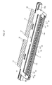
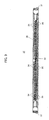
- a plug type connector 11 constituting the embodiment of cable connecting apparatus according to the present invention and a plurality of coaxial cables 12 coupled with the plug type connector 11 are shown.
- a side of the plug type connector 11 shown in a plane view of Fig. 3 is referred to as an upper side of the plug type connector 11 and a side opposite to the upper side of the plug type connector 11 is refereed to a lower side of the plug type connector 11.
- the plug type connector 11 comprises a housing 13 which is made of insulating material such as plastics.
- a plurality of contacts 15 each made of conductive material and a plurality of contacts 16 each made of conductive material are arranged one after the other in a longitudinal direction of the housing 13 (a longitudinal direction of the plug type connector 11 (left and right directions)).
- the contacts 15 and the contacts 16 constitute a plurality of plug contacts in the aggregate. That is, the plug contacts provided to be arranged on the housing 13 include the contacts 15 and the contacts 16 arranged one after the other.
- the coaxial cables 12 are connected respectively with the plug contacts including the contacts 15 and the contacts 16.
- a board-shaped portion 13a of the housing 13 on which the plug contacts including the contacts 15 and the contacts 16 are arranged forms a connectively engaging portion 17 elongating in the longitudinal direction of the housing 13.
- the connectively engaging portion 17 of the plug type connector 11 is caused to be inserted in a housing of a receptacle type connector described later, which constitutes the embodiment of cable connecting apparatus according to the present invention together with the plug type connector 11, through an opening provided on the housing of the receptacle type connector, so that the plug type connector 11 and the receptacle type connector are coupled with each other.
- a portion of each of the plug contacts with which the coaxial cable 12 is connected is concealed with a plug cover member 18 made of conductive material.
- the plug cover member 18 is provided with a pair of projections 18a at both end portions thereof in its longitudinal direction (the longitudinal direction of the plug type connector 11). The projections 18a are used for holding the plug type connector 11 when the plug type connector is pulled out of the receptacle type connector.
- each of the coaxial cables 12 coupled with the plug type connector 11 has a core conductor (signal conductor) 20, an inner insulating layer 21 surrounding the core conductor 20, an outer conductor (ground conductor) 22 surrounding the inner insulating layer 21 and an insulating cover 23 surrounding the outer conductor 22.
- Each of the contacts 15 provided on the connectively engaging portion 17 formed with the board-shaped portion 13a of the housing 13 has a cable connecting portion 25 with which the core conductor 20 of the coaxial cable 12 is connected, a contact-receiving portion 26 extending from the cable connecting portion 25 to be attached to the board-shaped portion 13a of the housing 13 on the upper side of the plug type connector 11, and a contact-receiving portion 27 folded back from the contact-receiving portion 26 to stick to the contact-receiving portion 26 on the lower side of the plug type connector 11.
- the contact-receiving portion 26 of the contact 15 is provided with a recess 26a with which a receptacle contact of the receptacle type connector comes into press-contact.
- a portion of the board-shaped portion 13a of the housing 13 on which the contact-receiving portion 26 of the contact 15 is placed is provided with a hole 14 at a position corresponding to the recess 26a.
- An insert pin for positioning the contact 15 is inserted through the hole 14 when the contacts 15 are fixed to the housing 13 by means on the insert method. With the hole 14 provided at the position corresponding to the recess 26a provided on the contact-receiving portion 26, each of the contacts 15 is precisely positioned on the board-shaped portion 13a of the housing 13.
- each of the contacts 16 provided on the connectively engaging portion 17 formed with the board-shaped portion 13a of the housing 13 has a cable connecting portion 28 with which the core conductor 20 of the coaxial cable 12 is connected, a contact-receiving portion 29 extending from the cable connecting portion 28 to be attached to the board-shaped portion 13a of the housing 13 on the lower side of the plug type connector 11, and a contact-receiving portion 30 folded back from the contact-receiving portion 29 to stick to the contact-receiving portion 29 on the upper side of the plug type connector 11.
- the contact-receiving portion 29 of the contact 16 is provided with a recess 29a with which the receptacle contact of the receptacle type connector comes into press-contact.
- a portion of the board-shaped portion 13a of the housing 13 on which the contact-receiving portion 29 of the contact 16 is placed is provided also with a hole 14 at a position corresponding to the recess 29a.
- An insert pin for positioning the contact 16 is inserted through the hole 14 when the contacts 16 are fixed to the housing 13 by means on the insert method. With the hole 14 provided at the position corresponding to the recess 29a provided on the contact-receiving portion 29, each of the contacts 16 is precisely positioned on the board-shaped portion 13a of the housing 13.
- the outer conductors 22 of the coaxial cables 12 each having the core conductor 20 connected with the cable connecting portion 25 of the contact 15 or the cable connecting portion 28 of the contact 16 are connected through a couple of ground bars 24 with the plug cover member 18.
- the connectively engaging portion 17 constituted as described above has upper and lower surfaces opposite to each other so that the contact-receiving portion 26 of each of the contacts 15 and the contact-receiving portion 30 of each of the contacts 16 are provided on the upper surface of the connectively engaging portion 17 and the contact-receiving portion 27 of each of the contacts 15 and the contact-receiving portion 29 of each of the contacts 16 are provided on the lower surface of the connectively engaging portion 17.
- a receptacle type connector 31 constituting the embodiment of cable connecting apparatus according to the present invention, together with the plug type connector 11, is shown.
- Fig. 9 shows a front end of the receptacle type connector 31.
- an end of the receptacle type connector 31 opposite to the front end shown in Fig. 9 is referred to as a rear end of the receptacle type connector 31 and an upper side, a lower side, a left side and a right side of the receptacle type connector 31 are defined with regard to the front end of the receptacle type connector 31 shown in Fig. 9 .
- the receptacle type connector 31 comprises a housing 32 which is made of insulating material such as plastics.
- the housing 32 is provided at its front end portion an opening 33 through which the connectively engaging portion 17 of the plug type connector 11 is inserted in the housing 32 when the plug type connector 11 is coupled with the receptacle type connector 31 and an accommodating space for the connectively engaging portion 17 of the plug type connector 11 is provided in the housing 32 to extend from the opening 33.
- the housing 32 is mounted on, for example, an electric circuit board not shown in the drawings so that the receptacle type connector 31 is fixed in its entirety to the electric circuit board.
- a plurality of contacts 34 each made of conductive material and a plurality of contacts 35 each made of conductive material are arranged one after the other in a longitudinal direction of the housing 32 (a longitudinal direction of the receptacle type connector 31 (the left and right directions)).
- the contacts 34 and the contacts 35 constitute a plurality of receptacle contacts in the aggregate. That is, the receptacle contacts provided to be arranged in the housing 32 include the contacts 34 and the contacts 35 arranged one after the other.
- the receptacle contacts including the contacts 34 and the contacts 35 are operative to come into press-contact respectively with the plug contacts provided on the connectively engaging portion 17 of the plug type connector 11 when the connectively engaging portion 17 of the plug type connector 11 is inserted in the housing 32 through the opening 33 provided thereon.
- the contacts 34 included in the receptacle contacts come into press-contact respectively with the contacts 15 included in the plug contacts and the contacts 35 included in the receptacle contacts come into press-contact respectively with the contacts 16 included in the plug contacts.
- the plug contacts provided on the connectively engaging portion 17 of the plug type connector 11 are connected through the receptacle contacts of the receptacle type connector 31 with circuit terminals provided on the electric circuit board to which the receptacle type connector 31 is fixed.
- the receptacle type connector 31 comprises also a conductive shell 36 mounted on the housing 32 for covering a major part of the housing 32 except the front end portion of the housing 32 at which the opening 33 is formed and a rear end portion, a small part of a left side end portion, a small part of a right side end portion and a part of a lower end portion of the housing 32. That is, the housing 32 is covered partially with the conductive shell 36.
- the conductive shell 36 is formed by means of processing a metal thin plate and grounded to be operative, for example, to contribute to adjustment on characteristic impedance of each of the receptacle contacts provided in the housing 32 and to shield the receptacle contacts provided in the housing 32 from electromagnetic wave noises coming from the outside.
- the conductive shell 36 is provided with a plurality of board connecting portions 37 at both end portions thereof in its longitudinal direction. Each of the board connecting portions 37 is connected with the electric circuit board to be fixed to the same by means of, for example, soldering when the receptacle type connector 31 is fixed in its entirety to the electric circuit board.
- the conductive shell 36 is also provided with a plurality of ground connecting portions 38, each of which is connected electrically with a grounded circuit portion provided on the electric circuit board when the receptacle type connector 31 is fixed in its entirety to the electric circuit board.
- each of the contacts 34 included in the receptacle contacts has a pair of an upper beam 41 and a lower beam 42 constituting a fork-shaped portion.
- the upper beam 41 and the lower beam 42 are provided to constitute respectively first and second contacting portions operative to be opposite to each other.
- the upper beam 41 constituting the first connecting portion has a contacting point 43 provided at a top end portion thereof.
- the lower beam 42 constituting the second connecting portion has a contacting point 44 provided at a central portion thereof and a connecting terminal 45 and an engaging projection 46 for engaging with the housing 32 provided respectively at both end portions thereof opposite to each other with the contacting point 44 between.
- a distance L1 from the front end portion 32a (in Fig. 10 ) of the housing 32 at which the opening 33 is formed to the contacting point 43 is set to be shorter than a distance L2 from the front end portion 32a of the housing 32 at which the opening 33 is formed to the contacting point 44. That is, the contacting point 44 provided at the central portion of the lower beam 42 is more distant from the front end portion 32a of the housing 32 at which the opening 33 is formed than the contacting point 43 provided at the top end portion of the upper beam 41.
- Each of the contacts 34 is formed by means of processing a resilient conductive plate to be punched. Allowable resilient deformation of the upper beam 41 is set to be larger than that of the lower beam 42 and therefore a resilient shift of the contacting point 43 is larger than that of the contacting point 44.
- the connecting terminal 45 provided at the end portion of the lower beam 42 is connected electrically by means of, for example, soldering with a corresponding one of the circuit terminals provided on the electric circuit board when the receptacle type connector 31 is fixed in its entirety to the electric circuit board.
- each of the contacts 35 included in the receptacle contacts has a pair of an upper beam 47 and a lower beam 48 constituting a fork-shaped portion in the similar manner as each of the first contacts 34.
- the upper beam 47 and the lower beam 48 are provided to constitute respectively third and fourth contacting portions operative to be opposite to each other.
- the upper beam 47 constituting the third connecting portion has a contacting point 49 provided at a top end portion thereof.
- the lower beam 48 constituting the fourth connecting portion has a contacting point 50 and a connecting terminal 51 provided respectively at both end portions thereof and an engaging projection 52 engaging with the housing 32 provided at a portion thereof between the contacting point 50 and the connecting terminal 51.
- a distance L3 from the front end portion 32a (in Fig. 11 ) of the housing 32 at which the opening 33 is formed to the contacting point 49 is set to be longer than a distance L4 from the front end portion 32a of the housing 32 at which the opening 33 is formed to the contacting point 50. That is, the contacting point 49 provided at the top end portion of the upper beam 47 is more distant from the front end portion 32a of the housing 32 at which the opening 33 is formed than the contacting point 50 provided at one of the end portions of the lower beam 48.
- Each of the contacts 35 is also formed by means of processing a resilient conductive plate to be punched. Allowable resilient deformation of the lower beam 48 is set to be larger than that of the upper beam 47 and therefore a resilient shift of the contacting point 50 is larger than that of the contacting point 49.
- the connecting terminal 51 provided at the other of the end portions of the lower beam 48 is connected electrically by means of, for example, soldering with a corresponding one of the circuit terminals provided on the electric circuit board when the receptacle type connector 31 is fixed in its entirety to the electric circuit board.
- Figs. 12 and 13 shows the embodiment of cable connector according to the present invention put in a condition wherein the connectively engaging portion 17 of the plug type connector 11 is inserted in the housing 32 of the receptacle type connector 31 through the opening 33 provided thereon so that the plug type connector 11 and the receptacle type connector 31 are coupled with each other.
- the connectively engaging portion 17 of the plug type connector 11 is positioned between the upper beam 41 and the lower beam 42 constituting the fork-shaped portion of each of the contacts 34 of the receptacle type connector 31, as shown in Fig. 12
- the contacting point 43 provided at the top end portion of the upper beam 41 of each of the contacts 34 is put in press-contact with the recess 26a provided on the contact-receiving portion 26 of a corresponding one of the contacts 15 on the side of the upper surface of the connectively engaging portion 17 of the plug type connector 11 and the contacting point 44 provided at the central portion of the lower beam 42 of the said contact 34 is put in press-contact with the contact-receiving portion 27 of the said contact 15 on the side of the lower surface of the connectively engaging portion 17 of the plug type connector 11.
- a position on each of the contacts 15 at which the contacting point 43 is put in press-contact with the recess 26a provided on the contact-receiving portion 26 on the side of the upper surface of the connectively engaging portion 17 is apart from a position on the said contact 15 at which the contacting point 44 is put in press-contact with the contact-receiving portion 27 on the side of the lower surface of the connectively engaging portion 17 in a direction along which the contacts 15 elongates.
- the connectively engaging portion 17 of the plug type connector 11 is positioned also between the upper beam 47 and the lower beam 48 constituting the fork-shaped portion of each of the contacts 35 of the receptacle type connector 31, as shown in Fig. 13
- the contacting point 50 provided at the end portion of the lower beam 48 of each of the contacts 35 is put in press-contact with the recess 29a provided on the contact-receiving portion 29 of a corresponding one of the contacts 16 on the side of the lower surface of the connectively engaging portion 17 of the plug type connector 11 and the contacting point 49 provided at the top end portion of the upper beam 47 of the said contact 35 is put in press-contact with the contact-receiving portion 30 of the said contact 16 on the side of the upper surface of the connectively engaging portion 17 of the plug type connector 11.
- a position on each of the contacts 16 at which the contacting point 50 is put in press-contact with the recess 29a provided on the contact-receiving portion 29 on the side of the lower surface of the connectively engaging portion 17 is apart from a position on the said contact 16 at which the contacting point 49 is put in press-contact with the contact-receiving portion 30 on the side of the upper surface of the connectively engaging portion 17 in a direction along which the contacts 16 elongates.
- the resilient shift of the contacting point 43 operative to exert the pressure to the connectively engaging portion 17 on the side of the upper surface thereof is larger than that of the contacting point 44 operative to exert the pressure to the connectively engaging portion 17 on the side of the lower surface thereof
- the resilient shift of the contacting point 50 operative to exert the pressure to the connectively engaging portion 17 on the side of the lower surface thereof is larger than that of the contacting point 49 operative to exert the pressure to the connectively engaging portion 17 on the side of the upper surface thereof
- the pressure by the contact 34 put in press-contact with the contact 15 concentrates to the particular portion of the contact 15 and the pressure by the contact 35 each put in press-contact with the contact 16 concentrates to the particular portion of the contact 16 when the contacts 34 come into press-contact respectively with the contacts 15 and the contacts 35 come into press-contact respectively with the contacts 16.
- the contacts 34 and the contacts 35 can be surely connected respectively with the contacts 15 and the contacts 16 provided on the connectively engaging portion 17 of the plug type connector 11 even if the connectively engaging portion 17 is improved to reduce its thickness and the connectively engaging portion 17 of the plug type connector 11 can be held stably without becoming unstable in its posture and bringing about undesirable changes in its posture and position when the contacts 34 and the contacts 35 are put in press-contact respectively with the contacts 15 and the contacts 16 provided on the connectively engaging portion 17 of the plug type connector 11.
- the contacts 15 and the contacts 16 are arranged one after the other on the connectively engaging portion 17 of the plug type connector 11 and, in correspondence therewith, the contacts 34 and the contacts 35 are arranged also one after the other in the housing 32 of the receptacle type connector 31, a condition wherein the contacts 34 and the contacts 35 are surely connected respectively with the contacts 15 and the contacts 16 provided on the connectively engaging portion 17 of the plug type connector 11 and the connectively engaging portion 17 of the plug type connector 11 is held stably without becoming unstable in its posture and bringing about undesirable changes in its posture and position when the contacts 34 and the contacts 35 are put in press-contact respectively with the contacts 15 and the contacts 16, can be obtained still more effectively,
- each of the contacts 15 has the contact-receiving portion 26 with which the contacting point 43 of the contact 34 of the receptacle type connector 31 comes into press-contact and the contact-receiving portion 27 folded back from the contact-receiving portion 26, with which the contacting point 44 of the contact 34 comes into press-contact
- each of the contacts 16 has the contact-receiving portion 29 with which the contacting point 50 of the contact 35 of the receptacle type connector 31 comes into press-contact and the contacting point 49 folded back from the contacting point 50, with which the contacting point 49 of the contact 35 comes into press-contact
- the top end portion of the contact-receiving portion 26 of each of the contacts 15 and the top end portion of the contact-receiving portion 29 of each of the contacts 16 are provided to be partially surrounded by the insulating material forming the connectively engaging portion 17 of the plug type
Abstract
Description
- The present invention relates generally to a cable connecting apparatus, and more particularly to an improvement in a cable connecting apparatus which comprises a plug type connector with which a plurality of cables such as coaxial cables are coupled and a receptacle type connector which is provided with an opening through which a connectively engaging portion of the plug type connector is inserted in the receptacle type connector, and is used for connecting electrically the cables coupled with the plug type connector with an electrical device such as an electric circuit board to which the receptacle type connector is fixed to be electrically connected therewith.
- When a plurality of cables such as coaxial cables for transmitting various kinds of electric signals, voltages and so on, each of which is relatively slender, are electrically connected to an electric circuit board, on which various electrical parts are mounted, in a such manner as to be bundled to form a thin flat cable assembly, there has been proposed to use often a cable connecting apparatus which is operative to mediate between the cables and the electric circuit board with which the cables are to be electrically connected. The cable connecting apparatus thus used comprises, for example, a plug type connector having a connectively engaging portion with which the cables are coupled and a receptacle type connector provided with an opening through which the connectively engaging portion of the plug type connector is inserted in the receptacle type connector.
- In the cable connecting apparatus used for connecting electrically the cables to the electric circuit board in such a manner as mentioned above, a plurality of plug contacts, with which the cables are connected respectively, are provided to be arranged on the connectively engaging portion of the plug type connector and a plurality of receptacle contacts, a portion of each of which is connected with a circuit portion provided on the electric circuit board, are provided to be arranged at the inside of the opening of the receptacle type connector. When the connectively engaging portion of the plug type connector is inserted through the opening in the receptacle type connector, the receptacle contacts come into press-contact respectively with the plug contacts to be electrically connected with the same so that the cables are electrically connected through the plug type and receptacle type connectors with the circuit portion on the electric circuit board.
- In regard to the cable connecting apparatus wherein the connectively engaging portion of the plug type connector is inserted in the receptacle type connector through the opening provided thereon as mentioned above, it has been desired to be miniaturized in thickness as a whole so as to connect the cables each of which is s still more slenderized with the electric circuit board which is still more miniaturized in size and reduced in weight. Accordingly, it has been required for the plug type connector to have an improved connectively engaging portion reduced in thickness as much as possible and it has been also required for the receptacle type connector to have a plurality of improved receptacle contacts which are able to come surely into press-contact respectively with the plug contacts provided on the connectively engaging portion of the plug type connector reduced in thickness and to keep the press-contact with the plug contacts stable.
- Under such a situation, there has been previously proposed a cable connecting apparatus comprising a plug type connector and a receptacle type connector to be used for connecting electrically a plurality of cables with an electric circuit board, wherein each of plug contacts provided on a connectively engaging portion of the plug type connector to be connected with the cable is formed to have a pair of contacting surfaces opposite to each other and each of receptacle contacts provided on the receptacle type connector is formed to have a pair of contacting portions operative to come into press-contact respectively with the contacting surfaces of the plug contact so as to cause the receptacle contact to be connected electrically with the plug contact, as disclosed in, for example, the Japanese patent application published before examination under publication number 2007-73426 (hereinafter, referred to as published patent document 1). Further, there has been also previously proposed another cable connecting apparatus comprising a plug type connector and a receptacle type connector to be used for connecting electrically a plurality of cables with an electric circuit board, wherein each of plug contacts provided on a connectively engaging portion of the plug type connector is formed to have a plate member extending along a core wire of the cable which is connected with the plug contact and having a pair of opposite surfaces, on one of which the core wire of the cable is placed, and each of receptacle contacts provided on the receptacle type connector is formed to have a contacting point operative to come into contact with the other of the opposite surfaces of the plate member of the plug contact so as to cause the receptacle contact to be connected electrically with the plug contact, as disclosed in, for example, the Japanese patent application published before examination under publication number
2005-158677 - In the previously proposed cable connecting apparatus disclosed in the published patent document 1, each of a plurality of plug contacts (male terminals 50) provided to be arranged on a connectively engaging portion of a plug type connector (a plug 2) is constituted to be a three-layer structure in which a conductive plate member is folded to form a pair of plate portions (the upper and
lower plate portion 52 and 53) facing each other with a plastic plate member which is a part of a housing (20) between or an incorporated structure formed by causing a relatively thick conductive plate member to be subjected to processing for punching so as to have a pair of contacting surfaces (an outer surface of anupper plate portion 52 and an outer surface of a lower plate portion 53) opposite to each other. Further, each of a plurality of receptacle contacts (female terminals 80) provided to be arranged on a receptacle type connector (a receptacle 6) is provided with a fork-shaped portion having a pair of contacting projections (contacting points 81 and 82) facing each other with the contacting surfaces of the plug contact constituted to be the three-layer structure or the incorporated structure between. - The contacting projections of each of the receptacle contacts are operative to come into contact respectively with the contacting surfaces of one of the plug contacts from the outside thereof so that the plug contacts are electrically connected respectively with the receptacle contacts.
- In another previously proposed cable connecting apparatus disclosed in the published patent document 2, each of a plurality of plug contacts (terminals 12) provided to be arranged on a connectively engaging portion forming a part of a housing (11) of a plug type connector (a cable connector 1) is provided with a plate member extending along a core wire (22a) of a cable (22) set to be soldered to the plate member so as to form a contacting portion (20) and an end portion of the plate member is folded back to form a projecting end portion (folded portion 18). Further, each of a plurality of receptacle contacts (terminals 33) provided to be arranged on a receptacle e type connector (a mate connector 31) is provided with a contacting point (36) operative to come into contact with a surface of the plate member of the plug contact, which is opposite to another surface of the plate member to which the core wire of the cable is soldered.
- With the contacting point of each of the receptacle contact put in contact with the surface of the plate member of each of the plug contact, the receptacle contact is electrically connected with the plug contact.
- In the cable connecting apparatus proposed previously as disclosed in the published patent document 1, which comprises the plug type connector and the receptacle type connector to be used for connecting electrically the cables with the electric circuit board and in which each of the plug contacts provided on the connectively engaging portion of the plug type connector is constituted to be the three-layer structure or the incorporated structure to form the contacting surfaces opposite to each other and each of the receptacle contacts provided on the receptacle type connector is provided with the fork-shaped portion having the contacting projections facing each other with the contacting surfaces of the plug contact constituted to be the three-layer structure or the incorporated structure between, the receptacle contact is operative to cause the contacting projections thereof to come into contact respectively with the contacting surfaces of the same portion of the plug contact in two directions opposite to each other when the contacting projections of each of the receptacle contacts comes into contact respectively with the contacting surfaces of one of the plug contacts from the outside thereof.
- Therefore, in each of the plug contacts, pressure by the contacting projections of the receptacle contact concentrates to a particular portion of the plug contact and such particular portions of the plug contacts are arranged in a line extending in a direction along which the plug contacts are arranged. As a result, it is feared that, under a condition where the connecting projections of each of the receptacle contacts are put in press-contact with one of the plug contacts, the connectively engaging portion of the plug type connector becomes unstable in its posture and brings about undesirable changes in its posture and position.
- Besides, in the case where each of the plug contacts is constituted to be the three-layer structure, it is difficult to reduce enough the thickness of each of the plug contacts and therefore also difficult to reduce effectively the thickness of the connectively engaging portion of the plug type connector, and in the case where each of the plug contacts is constituted to be the incorporated structure, it is required to cause the relatively thick conductive plate member to be subjected to processing for punching, which is improved to be extremely highly precise, and in addition it is feared that the plug contacts are not surely stuck on insulating material such as plastics forming the connectively engaging portion of the plug type connector.
- Further, in the cable connecting apparatus proposed previously as disclosed in the publication patent document 2, which comprises the plug type connector and the receptacle type connector to be used for connecting electrically the cables to the electric circuit board and in which each of the plug contacts is provided with the plate member to which the core wire of the cable are soldered for forming the contacting portion and the end portion of the plate member is folded back to form the projecting end portion and each of the receptacle contacts is provided with the contacting point operative to come into contact with the surface of the plate member of the plug contact, which is opposite to another surface of the plate member to which the core wire of the cable is soldered, since the plug contacts are pressed into the housing of the plug type connector and stuck on insulating material such as plastics forming the housing at a relatively small area, it is also feared that the plug contacts are not surely stuck on the insulating material forming the connectively engaging portion as the part of the housing of the plug type connector.
- Accordingly, it is an object of the present invention to provide a cable connecting apparatus comprising a plug type connector with which a plurality of cables are coupled and a receptacle type connector which is provided with an opening through which a connectively engaging portion of the plug type connector is inserted in the receptacle type connector to be used for connecting electrically the cables coupled with to the plug type connector with an electrical device such as an electric circuit board, which avoids the aforementioned problems and disadvantages encountered with the prior art.
- Another object of the present invention is to provide a cable connecting apparatus comprising a plug type connector with which a plurality of cables are coupled and a receptacle type connector which is provided with an opening through which a connectively engaging portion of the plug type connector is inserted in the receptacle type connector to be used for connecting electrically the cables coupled with the plug type connector with an electrical device such as an electric circuit board, in which a plurality of receptacle contacts provided on the receptacle type connector can be surely connected respectively with a plurality of plug contacts provided on the connectively engaging portion of the plug type connector even if the connectively engaging portion is improved to reduce its thickness.
- A further object of the present invention is to provide a cable connecting apparatus comprising a plug type connector with which a plurality of cables are coupled and a receptacle type connector which is provided with an opening through which a connectively engaging portion of the plug type connector is inserted in the receptacle type connector to be used for connecting electrically the cables coupled with the plug type connector with an electrical device such as an electric circuit board, in which the connectively engaging portion of the plug type connector can be held stably without becoming unstable in its posture and bringing about undesirable changes in its posture and position under a condition where the receptacle contacts are put in press-contact respectively with the plug contacts.
- A still further object of the present invention is to provide a cable connecting apparatus comprising a plug type connector with which a plurality of cables are coupled and a receptacle type connector which is provided with an opening through which a connectively engaging portion of the plug type connector is inserted in the receptacle type connector to be used for connecting electrically the cables coupled with the plug type connector with an electrical device such as an electric circuit board, in which the connectively engaging portion of the plug type connector can be reduced effectively in its thickness and provided with the plug contacts stuck firmly on insulating material forming the connectively engaging portion of the plug type connector.
- According to the present invention, as claimed in accompanying claims, there is provided a cable connecting apparatus, which comprises a plug type connector having a connectively engaging portion on which a plurality of plug contacts are arranged to be connected with a plurality of cables and a receptacle type connector having a housing on which an opening through which the connectively engaging portion of the plug type connector is inserted in the housing is provided to be formed at an end portion of the housing and a plurality of receptacle contacts arranged in the housing for coming into press-contact with the plug contacts arranged on the connectively engaging portion of the plug type connector inserted in the housing through the opening provided thereon. The receptacle contacts include a plurality of first contacts and a plurality of second contacts. Each of the first contacts has first and second contacting portions operative to be opposite to each other with the connectively engaging portion of the plug type connector inserted in the housing through the opening provided thereon between. The first and second contacting portions have respectively first and second contacting points and a distance from the end portion of the housing at which the opening is formed to the first contacting point is shorter than a distance from the end portion of the housing at which the opening is formed to the second contacting point. The first contacting point is operative to come into press-contact with the plug contact on the side of a first surface of the connectively engaging portion of the plug type connector and the second contacting point is operative to come into press-contact with the plug contact on the side of a second surface opposite to the first surface of the connectively engaging portion of the plug type connector. Further, each of the second contacts has third and fourth contacting portions operative to be opposite to each other with the connectively engaging portion of the plug type connector inserted in the housing through the opening provided thereon between. The third and fourth contacting portions have third and fourth contacting points, respectively, and a distance from the end portion of the housing at which the opening is formed to the third contacting point is longer than a distance from the end portion of the housing at which the opening is formed to the fourth contacting point. The third contacting point is operative to come into press-contact with the plug contact on the side of the first surface of the connectively engaging portion of the plug type connector and the fourth contacting point is operative to come into press-contact with the plug contact on the side of the second surface opposite to the first surface of the connectively engaging portion of the plug type connector.
- In the cable connecting apparatus thus constituted in accordance with the present invention, when the connectively engaging portion of the plug type connector is inserted in the housing of the receptacle type connector through the opening provided thereon, the receptacle contacts arranged in the housing of the receptacle type connector come into press-contact respectively with the plug contacts arranged on the connectively engaging portion of the plug type connector. In such a condition, the first and second contacting points provided respectively on the first and second connecting portions of each of the first contacts contained in the receptacle contacts are put in press-contact with a corresponding one of the plug contacts and the third and fourth contacting points provided respectively on the third and fourth connecting portions of each of the second contacts contained in the receptacle contacts are also put in press-contact with a corresponding one of the plug contacts. The first and second connecting points are placed respectively at such positions that the distance from the end portion of the housing at which the opening is formed to the first contacting point is shorter than the distance from the end portion of the housing at which the opening is formed to the second contacting point so that the first contacting point is put in press-contact with the plug contact on the side of the first surface of the connectively engaging portion of the plug type connector and the second contacting point is put in press-contact with the plug contact on the side of the second surface opposite to the first surface of the connectively engaging portion of the plug type connector. Further, the third and fourth connecting points are placed respectively at such positions that the distance from the end portion of the housing at which the opening is formed to the third contacting point is longer than the distance from the end portion of the housing at which the opening is formed to the fourth contacting point so that the third contacting point is put in press-contact with the plug contact on the side of the first surface of the connectively engaging portion of the plug type connector and the fourth contacting point is put in press-contact with the plug contact on the side of the second surface opposite to the first surface of the connectively engaging portion of the plug type connector.
- That is, the first and second contacting points provided respectively on the first and second connecting portions of each of the first contacts included in the receptacle contacts are put in press-contact with the plug contact respectively on the sides of the first and second surfaces of the connectively engaging portion of the plug type connector at respective positions remote from each other in a direction along which the connectively engaging portion of the plug type connector is inserted in the housing of the receptacle type connector through the opening provided thereon, and the third and fourth contacting points provided respectively on the third and fourth connecting portions of each of the second contacts included in the receptacle contacts are also put in press-contact with the plug contact respectively on the sides of the first and second surfaces of the connectively engaging portion of the plug type connector at respective positions remote from each other in the direction along which the connectively engaging portion of the plug type connector is inserted in the housing of the receptacle type connector through the opening provided thereon. Consequently, the first and second contacts included in the receptacle contacts come into press-contact with respective portions apart from each other of one of the plug contacts from respective directions opposite to each other.
- Especially, in a first example of cable connecting apparatus according to the present invention, such as claimed in claim 3, the first and second contacts included in the receptacle contacts are arranged one after the other in the direction along which the receptacle contacts are arranged.
- Further, in a second example of cable connecting apparatus according to the present invention, such as claimed in claim 4, the plug contacts include a plurality of third contacts and a plurality of fourth contacts, which are arranged one after the other in the direction along which the plug contacts are arranged. Each of the third contacts has a cable connecting portion with which the cable is connected, a first contact-receiving portion with which one of the first and second contacting points of the first contact comes into press-contact and a second contact-receiving portion folded back from the first contact-receiving portion, with which the other of the first and second contacting points of the first contact comes into press-contact. Each of the fourth contacts has a cable connecting portion with which the cable is connected, a third contact-receiving portion with which one of the third and fourth contacting points of the second contact comes into press-contact and a fourth contact-receiving portion folded back from the third contact-receiving portion, with which the other of the third and fourth contacting points of the second contact comes into press-contact. A top end portion of the second contact-receiving portion of each of the third contacts and a top end portion of the fourth contact-receiving portion of each of the fourth contacts are provided to be partially surrounded by the insulating material forming the connectively engaging portion of the plug type connector.
- In the cable connecting apparatus according to the present invention, as described above, the first and second contacts included in the receptacle contacts come into press-contact with the respective portions apart from each other of one of the plug contacts provided on the connectively engaging portion of the plug type connector from the respective directions opposite to each other. Accordingly, with the cable connecting apparatus according to the present invention, it can be avoided that pressure by the first and second contacts each put in press-contact with the plug contact provided on the connectively engaging portion of the plug type connector concentrates to a particular portion of the plug contact. Therefore, the receptacle contacts can be surely connected respectively with the plug contacts provided on the connectively engaging portion of the plug type connector even if the connectively engaging portion is improved to reduce its thickness, and the connectively engaging portion of the plug type connector can be held stably without becoming unstable in its posture and bringing about undesirable changes in its posture and position when the receptacle contacts are put in press-contact respectively with the plug contacts.
- Especially, with the first example of cable connecting apparatus according to the present invention, such as claimed in claim 3, since the first and second contacts included in the receptacle contacts are arranged one after the other in the direction along which the receptacle contacts are arranged, a condition wherein the receptacle contacts are surely connected respectively with the plug contacts provided on the connectively engaging portion of the plug type connector and the connectively engaging portion of the plug type connector is held stably without becoming unstable in its posture and bringing about undesirable changes in its posture and position when the receptacle contacts are put in press-contact respectively with the plug contacts, can be obtained still more effectively,
- Further, in the second example of cable connecting apparatus according to the present invention, such as claimed in claim 4, as described above, the plug contacts include the third contacts and the fourth contacts, each of the third contacts has the first contact-receiving portion with which one of the first and second contacting points of the first contact comes into press-contact and the second contact-receiving portion folded back from the first contact-receiving portion, with which the other of the first and second contacting points of the first contact comes into press-contact, each of the fourth contacts has the third contact-receiving portion with which one of the third and fourth contacting points of the second contact comes into press-contact and the fourth contact-receiving portion folded back from the third contact-receiving portion, with which the other of the third and fourth contacting points of the second contact comes into press-contact, and the top end portion of the second contact-receiving portion of each of the third contacts and the top end portion of the fourth contact-receiving portion of each of the fourth contacts are provided to be partially surrounded by the insulating material forming the connectively engaging portion of the plug type connector. Accordingly, with the second example of cable connecting apparatus according to the present invention, the connectively engaging portion of the plug type connector can be reduced effectively in its thickness and provided with the plug contacts stuck firmly on the insulating material forming the connectively engaging portion of the plug type connector.
- The above, and other objects, features and advantages of the present invention will become apparent from the following detailed description taken in conjunction with the accompanying drawings.
-
-
Fig. 1 is a schematic top perspective view showing a plug type connector constituting an embodiment of cable connecting apparatus according to the present invention; -
Fig. 2 is a schematic bottom perspective view showing the plug type connector constituting the embodiment of cable connecting apparatus according to the present invention, together with a plurality of coaxial cables coupled with therewith; -
Fig. 3 is a schematic plane view showing the plug type connector constituting the embodiment of cable connecting apparatus according to the present invention, together with a plurality of coaxial cables coupled therewith; -
Fig. 4 is a schematic cross sectional view taken along line IV-IV onFig. 3 ; -
Fig. 5 is a schematic cross sectional view taken along line V-V onFig. 3 ; -
Fig. 6 is a schematic front perspective view showing a receptacle type connector constituting the embodiment of cable connecting apparatus according to the present invention; -
Fig. 7 is a schematic rear perspective view showing the receptacle type connector constituting the embodiment of cable connecting apparatus according to the present invention; -
Fig. 8 is a schematic plane view showing the receptacle type connector constituting the embodiment of cable connecting apparatus according to the present invention; -
Fig. 9 is a schematic front view showing the receptacle type connector constituting the embodiment of cable connecting apparatus according to the present invention; -
Fig. 10 is a schematic cross sectional view taken along line X-X onFig. 8 ; -
Fig. 11 is a schematic cross sectional view taken along line XI-XI onFig. 8 ; -
Fig. 12 is a schematic cross sectional view showing the plug type and receptacle type connectors constituting the embodiment of cable connecting apparatus according to the present invention, which are coupled with each other, together with the coaxial cable coupled with the plug type connector; and -
Fig. 13 is a schematic cross sectional view showing the plug type and receptacle type connectors constituting the embodiment of cable connecting apparatus according to the present invention, which are coupled with each other, together with the coaxial cable coupled with the plug type connector. - An embodiment of cable connecting apparatus according to the present invention will be explained with reference to
Figs. 1 to 13 . - In
Figs. 1 ,2 and3 , aplug type connector 11 constituting the embodiment of cable connecting apparatus according to the present invention and a plurality ofcoaxial cables 12 coupled with theplug type connector 11 are shown. For the sake of convenience, hereinafter, a side of theplug type connector 11 shown in a plane view ofFig. 3 is referred to as an upper side of theplug type connector 11 and a side opposite to the upper side of theplug type connector 11 is refereed to a lower side of theplug type connector 11. - The
plug type connector 11 comprises ahousing 13 which is made of insulating material such as plastics. On thehousing 13, a plurality ofcontacts 15 each made of conductive material and a plurality ofcontacts 16 each made of conductive material are arranged one after the other in a longitudinal direction of the housing 13 (a longitudinal direction of the plug type connector 11 (left and right directions)). Thecontacts 15 and thecontacts 16 constitute a plurality of plug contacts in the aggregate. That is, the plug contacts provided to be arranged on thehousing 13 include thecontacts 15 and thecontacts 16 arranged one after the other. Thecoaxial cables 12 are connected respectively with the plug contacts including thecontacts 15 and thecontacts 16. - A board-shaped
portion 13a of thehousing 13 on which the plug contacts including thecontacts 15 and thecontacts 16 are arranged forms aconnectively engaging portion 17 elongating in the longitudinal direction of thehousing 13. Theconnectively engaging portion 17 of theplug type connector 11 is caused to be inserted in a housing of a receptacle type connector described later, which constitutes the embodiment of cable connecting apparatus according to the present invention together with theplug type connector 11, through an opening provided on the housing of the receptacle type connector, so that theplug type connector 11 and the receptacle type connector are coupled with each other. - A portion of each of the plug contacts with which the
coaxial cable 12 is connected is concealed with aplug cover member 18 made of conductive material. Theplug cover member 18 is provided with a pair ofprojections 18a at both end portions thereof in its longitudinal direction (the longitudinal direction of the plug type connector 11). Theprojections 18a are used for holding theplug type connector 11 when the plug type connector is pulled out of the receptacle type connector. - As shown in
Fig. 4 representing a cross section taken along line IV-IV onFig. 3 , each of thecoaxial cables 12 coupled with theplug type connector 11 has a core conductor (signal conductor) 20, an inner insulatinglayer 21 surrounding thecore conductor 20, an outer conductor (ground conductor) 22 surrounding the inner insulatinglayer 21 and an insulatingcover 23 surrounding theouter conductor 22. Each of thecontacts 15 provided on theconnectively engaging portion 17 formed with the board-shapedportion 13a of thehousing 13 has acable connecting portion 25 with which thecore conductor 20 of thecoaxial cable 12 is connected, a contact-receivingportion 26 extending from thecable connecting portion 25 to be attached to the board-shapedportion 13a of thehousing 13 on the upper side of theplug type connector 11, and a contact-receivingportion 27 folded back from the contact-receivingportion 26 to stick to the contact-receivingportion 26 on the lower side of theplug type connector 11. - The contact-receiving
portion 26 of thecontact 15 is provided with arecess 26a with which a receptacle contact of the receptacle type connector comes into press-contact. A portion of the board-shapedportion 13a of thehousing 13 on which the contact-receivingportion 26 of thecontact 15 is placed is provided with ahole 14 at a position corresponding to therecess 26a. An insert pin for positioning thecontact 15 is inserted through thehole 14 when thecontacts 15 are fixed to thehousing 13 by means on the insert method. With thehole 14 provided at the position corresponding to therecess 26a provided on the contact-receivingportion 26, each of thecontacts 15 is precisely positioned on the board-shapedportion 13a of thehousing 13. - Further, as shown in
Fig. 5 representing a cross section taken along line V-V onFig. 3 , each of thecontacts 16 provided on theconnectively engaging portion 17 formed with the board-shapedportion 13a of thehousing 13 has acable connecting portion 28 with which thecore conductor 20 of thecoaxial cable 12 is connected, a contact-receivingportion 29 extending from thecable connecting portion 28 to be attached to the board-shapedportion 13a of thehousing 13 on the lower side of theplug type connector 11, and a contact-receivingportion 30 folded back from the contact-receivingportion 29 to stick to the contact-receivingportion 29 on the upper side of theplug type connector 11. - The contact-receiving
portion 29 of thecontact 16 is provided with arecess 29a with which the receptacle contact of the receptacle type connector comes into press-contact. A portion of the board-shapedportion 13a of thehousing 13 on which the contact-receivingportion 29 of thecontact 16 is placed is provided also with ahole 14 at a position corresponding to therecess 29a. An insert pin for positioning thecontact 16 is inserted through thehole 14 when thecontacts 16 are fixed to thehousing 13 by means on the insert method. With thehole 14 provided at the position corresponding to therecess 29a provided on the contact-receivingportion 29, each of thecontacts 16 is precisely positioned on the board-shapedportion 13a of thehousing 13. - Incidentally, the
outer conductors 22 of thecoaxial cables 12 each having thecore conductor 20 connected with thecable connecting portion 25 of thecontact 15 or thecable connecting portion 28 of thecontact 16 are connected through a couple of ground bars 24 with theplug cover member 18. - The
connectively engaging portion 17 constituted as described above has upper and lower surfaces opposite to each other so that the contact-receivingportion 26 of each of thecontacts 15 and the contact-receivingportion 30 of each of thecontacts 16 are provided on the upper surface of theconnectively engaging portion 17 and the contact-receivingportion 27 of each of thecontacts 15 and the contact-receivingportion 29 of each of thecontacts 16 are provided on the lower surface of theconnectively engaging portion 17. - In the
connectively engaging portion 17 on which thecontacts 15 and thecontacts 16 are arranged one after the other, since each of thecontacts 15 is folded back from the upper surface of theconnectively engaging portion 17 to the lower surface of theconnectively engaging portion 17 and each of thecontacts 16 is folded back from the lower surface of theconnectively engaging portion 17 to the upper surface of theconnectively engaging portion 17, upper and lower surfaces of the insulating material forming the board-shapedportion 13a of thehousing 13 are provided to be well-balanced both on the side of the upper surface of theconnectively engaging portion 17 and on the side of the lower surface of theconnectively engaging portion 17. This results in that theconnectively engaging portion 17 has been formed appropriately so as to able to avoid deformations brought about after its formation. - In
Figs. 6 ,7 ,8 and9 , areceptacle type connector 31 constituting the embodiment of cable connecting apparatus according to the present invention, together with theplug type connector 11, is shown. Especially,Fig. 9 shows a front end of thereceptacle type connector 31. For the sake of convenience, hereinafter, an end of thereceptacle type connector 31 opposite to the front end shown inFig. 9 is referred to as a rear end of thereceptacle type connector 31 and an upper side, a lower side, a left side and a right side of thereceptacle type connector 31 are defined with regard to the front end of thereceptacle type connector 31 shown inFig. 9 . - Referring to
Figs. 6 to 9 , thereceptacle type connector 31 comprises ahousing 32 which is made of insulating material such as plastics. Thehousing 32 is provided at its front end portion anopening 33 through which theconnectively engaging portion 17 of theplug type connector 11 is inserted in thehousing 32 when theplug type connector 11 is coupled with thereceptacle type connector 31 and an accommodating space for theconnectively engaging portion 17 of theplug type connector 11 is provided in thehousing 32 to extend from theopening 33. Thehousing 32 is mounted on, for example, an electric circuit board not shown in the drawings so that thereceptacle type connector 31 is fixed in its entirety to the electric circuit board. - In the
housing 32, a plurality ofcontacts 34 each made of conductive material and a plurality ofcontacts 35 each made of conductive material are arranged one after the other in a longitudinal direction of the housing 32 (a longitudinal direction of the receptacle type connector 31 (the left and right directions)). Thecontacts 34 and thecontacts 35 constitute a plurality of receptacle contacts in the aggregate. That is, the receptacle contacts provided to be arranged in thehousing 32 include thecontacts 34 and thecontacts 35 arranged one after the other. - The receptacle contacts including the
contacts 34 and thecontacts 35 are operative to come into press-contact respectively with the plug contacts provided on theconnectively engaging portion 17 of theplug type connector 11 when theconnectively engaging portion 17 of theplug type connector 11 is inserted in thehousing 32 through theopening 33 provided thereon. On that occasion, thecontacts 34 included in the receptacle contacts come into press-contact respectively with thecontacts 15 included in the plug contacts and thecontacts 35 included in the receptacle contacts come into press-contact respectively with thecontacts 16 included in the plug contacts. Thereby, the plug contacts provided on theconnectively engaging portion 17 of theplug type connector 11 are connected through the receptacle contacts of thereceptacle type connector 31 with circuit terminals provided on the electric circuit board to which thereceptacle type connector 31 is fixed. - The
receptacle type connector 31 comprises also aconductive shell 36 mounted on thehousing 32 for covering a major part of thehousing 32 except the front end portion of thehousing 32 at which theopening 33 is formed and a rear end portion, a small part of a left side end portion, a small part of a right side end portion and a part of a lower end portion of thehousing 32. That is, thehousing 32 is covered partially with theconductive shell 36. - The
conductive shell 36 is formed by means of processing a metal thin plate and grounded to be operative, for example, to contribute to adjustment on characteristic impedance of each of the receptacle contacts provided in thehousing 32 and to shield the receptacle contacts provided in thehousing 32 from electromagnetic wave noises coming from the outside. - The
conductive shell 36 is provided with a plurality ofboard connecting portions 37 at both end portions thereof in its longitudinal direction. Each of theboard connecting portions 37 is connected with the electric circuit board to be fixed to the same by means of, for example, soldering when thereceptacle type connector 31 is fixed in its entirety to the electric circuit board. Theconductive shell 36 is also provided with a plurality ofground connecting portions 38, each of which is connected electrically with a grounded circuit portion provided on the electric circuit board when thereceptacle type connector 31 is fixed in its entirety to the electric circuit board. - As shown in
Fig. 10 representing a cross section taken along line X-X onFig. 8 , each of thecontacts 34 included in the receptacle contacts has a pair of anupper beam 41 and alower beam 42 constituting a fork-shaped portion. Theupper beam 41 and thelower beam 42 are provided to constitute respectively first and second contacting portions operative to be opposite to each other. Theupper beam 41 constituting the first connecting portion has a contactingpoint 43 provided at a top end portion thereof. Thelower beam 42 constituting the second connecting portion has a contactingpoint 44 provided at a central portion thereof and a connectingterminal 45 and an engagingprojection 46 for engaging with thehousing 32 provided respectively at both end portions thereof opposite to each other with the contactingpoint 44 between. - Under such a situation, a distance L1 from the
front end portion 32a (inFig. 10 ) of thehousing 32 at which theopening 33 is formed to the contactingpoint 43 is set to be shorter than a distance L2 from thefront end portion 32a of thehousing 32 at which theopening 33 is formed to the contactingpoint 44. That is, the contactingpoint 44 provided at the central portion of thelower beam 42 is more distant from thefront end portion 32a of thehousing 32 at which theopening 33 is formed than the contactingpoint 43 provided at the top end portion of theupper beam 41. - Each of the
contacts 34 is formed by means of processing a resilient conductive plate to be punched. Allowable resilient deformation of theupper beam 41 is set to be larger than that of thelower beam 42 and therefore a resilient shift of the contactingpoint 43 is larger than that of the contactingpoint 44. The connectingterminal 45 provided at the end portion of thelower beam 42 is connected electrically by means of, for example, soldering with a corresponding one of the circuit terminals provided on the electric circuit board when thereceptacle type connector 31 is fixed in its entirety to the electric circuit board. - Further, as shown in
Fig. 11 representing a cross section taken along line XI-XI onFig. 8 , each of thecontacts 35 included in the receptacle contacts has a pair of anupper beam 47 and alower beam 48 constituting a fork-shaped portion in the similar manner as each of thefirst contacts 34. Theupper beam 47 and thelower beam 48 are provided to constitute respectively third and fourth contacting portions operative to be opposite to each other. Theupper beam 47 constituting the third connecting portion has a contactingpoint 49 provided at a top end portion thereof. Thelower beam 48 constituting the fourth connecting portion has a contactingpoint 50 and a connectingterminal 51 provided respectively at both end portions thereof and an engagingprojection 52 engaging with thehousing 32 provided at a portion thereof between the contactingpoint 50 and the connectingterminal 51. - Under such a situation, a distance L3 from the
front end portion 32a (inFig. 11 ) of thehousing 32 at which theopening 33 is formed to the contactingpoint 49 is set to be longer than a distance L4 from thefront end portion 32a of thehousing 32 at which theopening 33 is formed to the contactingpoint 50. That is, the contactingpoint 49 provided at the top end portion of theupper beam 47 is more distant from thefront end portion 32a of thehousing 32 at which theopening 33 is formed than the contactingpoint 50 provided at one of the end portions of thelower beam 48. - Each of the
contacts 35 is also formed by means of processing a resilient conductive plate to be punched. Allowable resilient deformation of thelower beam 48 is set to be larger than that of theupper beam 47 and therefore a resilient shift of the contactingpoint 50 is larger than that of the contactingpoint 49. The connectingterminal 51 provided at the other of the end portions of thelower beam 48 is connected electrically by means of, for example, soldering with a corresponding one of the circuit terminals provided on the electric circuit board when thereceptacle type connector 31 is fixed in its entirety to the electric circuit board. -
Figs. 12 and 13 shows the embodiment of cable connector according to the present invention put in a condition wherein theconnectively engaging portion 17 of theplug type connector 11 is inserted in thehousing 32 of thereceptacle type connector 31 through theopening 33 provided thereon so that theplug type connector 11 and thereceptacle type connector 31 are coupled with each other. - Under the condition wherein the
connectively engaging portion 17 of theplug type connector 11 is inserted in thehousing 32 of thereceptacle type connector 31 through theopening 33 provided thereon, theconnectively engaging portion 17 of theplug type connector 11 is positioned between theupper beam 41 and thelower beam 42 constituting the fork-shaped portion of each of thecontacts 34 of thereceptacle type connector 31, as shown inFig. 12 - The contacting
point 43 provided at the top end portion of theupper beam 41 of each of thecontacts 34 is put in press-contact with therecess 26a provided on the contact-receivingportion 26 of a corresponding one of thecontacts 15 on the side of the upper surface of theconnectively engaging portion 17 of theplug type connector 11 and the contactingpoint 44 provided at the central portion of thelower beam 42 of the saidcontact 34 is put in press-contact with the contact-receivingportion 27 of the saidcontact 15 on the side of the lower surface of theconnectively engaging portion 17 of theplug type connector 11. On that occasion, a position on each of thecontacts 15 at which the contactingpoint 43 is put in press-contact with therecess 26a provided on the contact-receivingportion 26 on the side of the upper surface of theconnectively engaging portion 17 is apart from a position on the saidcontact 15 at which the contactingpoint 44 is put in press-contact with the contact-receivingportion 27 on the side of the lower surface of theconnectively engaging portion 17 in a direction along which thecontacts 15 elongates. - This results in that a portion of the
contact 15 to which the contactingpoint 43 exerts pressure on the side of the upper surface of theconnectively engaging portion 17 is apart from a portion of thecontact 15 to which the contactingpoint 44 exerts pressure on the side of the lower surface of theconnectively engaging portion 17 and therefore it can be avoided that the pressure by thecontacts 34 each put in press-contact with thecontact 15 concentrates to a particular portion of thecontact 15. - Further, under the condition wherein the
connectively engaging portion 17 of theplug type connector 11 is inserted in thehousing 32 of thereceptacle type connector 31 through theopening 33 provided thereon, theconnectively engaging portion 17 of theplug type connector 11 is positioned also between theupper beam 47 and thelower beam 48 constituting the fork-shaped portion of each of thecontacts 35 of thereceptacle type connector 31, as shown inFig. 13 - The contacting
point 50 provided at the end portion of thelower beam 48 of each of thecontacts 35 is put in press-contact with therecess 29a provided on the contact-receivingportion 29 of a corresponding one of thecontacts 16 on the side of the lower surface of theconnectively engaging portion 17 of theplug type connector 11 and the contactingpoint 49 provided at the top end portion of theupper beam 47 of the saidcontact 35 is put in press-contact with the contact-receivingportion 30 of the saidcontact 16 on the side of the upper surface of theconnectively engaging portion 17 of theplug type connector 11. On that occasion, a position on each of thecontacts 16 at which the contactingpoint 50 is put in press-contact with therecess 29a provided on the contact-receivingportion 29 on the side of the lower surface of theconnectively engaging portion 17 is apart from a position on the saidcontact 16 at which the contactingpoint 49 is put in press-contact with the contact-receivingportion 30 on the side of the upper surface of theconnectively engaging portion 17 in a direction along which thecontacts 16 elongates. - This results in that a portion of the
contact 16 to which the contactingpoint 50 exerts pressure on the side of the lower surface of theconnectively engaging portion 17 is apart from a portion of thecontact 16 to which the contactingpoint 49 exerts pressure on the side of the upper surface of theconnectively engaging portion 17 and therefore it can be avoided that the pressure by thecontacts 35 each put in press-contact with thecontact 16 concentrates to a particular portion of thecontact 16. - Besides, since, in each of the
contacts 34, the resilient shift of the contactingpoint 43 operative to exert the pressure to theconnectively engaging portion 17 on the side of the upper surface thereof is larger than that of the contactingpoint 44 operative to exert the pressure to theconnectively engaging portion 17 on the side of the lower surface thereof, and in each of thecontacts 35, the resilient shift of the contactingpoint 50 operative to exert the pressure to theconnectively engaging portion 17 on the side of the lower surface thereof is larger than that of the contactingpoint 49 operative to exert the pressure to theconnectively engaging portion 17 on the side of the upper surface thereof, the pressure exerted by thecontacts 34 and thecontacts 35 to theconnectively engaging portion 17 on the side of the upper surface thereof and the pressure exerted by thecontacts 34 and thecontacts 35 to theconnectively engaging portion 17 on the side of the lower surface thereof are well-balanced. - As described above, in the embodiment of cable connector according to the present invention which comprises the
plug type connector 11 and thereceptacle type connector 31, it can be avoided that the pressure by thecontact 34 put in press-contact with thecontact 15 concentrates to the particular portion of thecontact 15 and the pressure by thecontact 35 each put in press-contact with thecontact 16 concentrates to the particular portion of thecontact 16 when thecontacts 34 come into press-contact respectively with thecontacts 15 and thecontacts 35 come into press-contact respectively with thecontacts 16. Therefore, thecontacts 34 and thecontacts 35 can be surely connected respectively with thecontacts 15 and thecontacts 16 provided on theconnectively engaging portion 17 of theplug type connector 11 even if theconnectively engaging portion 17 is improved to reduce its thickness and theconnectively engaging portion 17 of theplug type connector 11 can be held stably without becoming unstable in its posture and bringing about undesirable changes in its posture and position when thecontacts 34 and thecontacts 35 are put in press-contact respectively with thecontacts 15 and thecontacts 16 provided on theconnectively engaging portion 17 of theplug type connector 11. - Especially, since the
contacts 15 and thecontacts 16 are arranged one after the other on theconnectively engaging portion 17 of theplug type connector 11 and, in correspondence therewith, thecontacts 34 and thecontacts 35 are arranged also one after the other in thehousing 32 of thereceptacle type connector 31, a condition wherein thecontacts 34 and thecontacts 35 are surely connected respectively with thecontacts 15 and thecontacts 16 provided on theconnectively engaging portion 17 of theplug type connector 11 and theconnectively engaging portion 17 of theplug type connector 11 is held stably without becoming unstable in its posture and bringing about undesirable changes in its posture and position when thecontacts 34 and thecontacts 35 are put in press-contact respectively with thecontacts 15 and thecontacts 16, can be obtained still more effectively, - Further, since the plug contacts provided on the connectively engaging portion 17 of the plug type connector 11 include the contacts 15 and the contacts 16 arranged one after the other, each of the contacts 15 has the contact-receiving portion 26 with which the contacting point 43 of the contact 34 of the receptacle type connector 31 comes into press-contact and the contact-receiving portion 27 folded back from the contact-receiving portion 26, with which the contacting point 44 of the contact 34 comes into press-contact, each of the contacts 16 has the contact-receiving portion 29 with which the contacting point 50 of the contact 35 of the receptacle type connector 31 comes into press-contact and the contacting point 49 folded back from the contacting point 50, with which the contacting point 49 of the contact 35 comes into press-contact, and the top end portion of the contact-receiving portion 26 of each of the contacts 15 and the top end portion of the contact-receiving portion 29 of each of the contacts 16 are provided to be partially surrounded by the insulating material forming the connectively engaging portion 17 of the plug type connector 11, the connectively engaging portion 17 of the plug type connector 11 can be reduced effectively in its thickness and provided with the contacts 34 and the contacts 35 each stuck firmly on the insulating material forming the connectively engaging portion 17 of the plug type connector 11.
- In addition, since the contacting
point 43 provided at the top end portion of theupper beam 41 of each of thecontacts 34 comes into press-contact with therecess 26a provided on the contact-receivingportion 26 of the corresponding one of thecontacts 15 and the contactingpoint 50 provided at the end portion of thelower beam 48 of each of thecontacts 35 comes into press-contact with therecess 29a provided on the contact-receivingportion 29 of the corresponding one of thecontacts 16 6 when thecontacts 34 come into press-contact respectively with thecontacts 15 and thecontacts 35 come into press-contact respectively with thecontacts 16, the contactingpoint 43 and therecess 26a engaging with each other produce a click and the contactingpoint 50 and therecess 29a engaging with each other produce also a click when theconnectively engaging portion 17 of theplug type connector 11 is inserted in thehousing 32 of thereceptacle type connector 31 through theopening 33 provided thereon, and the contactingpoint 43 meets with resistance caused by therecess 26a and the contactingpoint 50 meets also with resistance caused by therecess 29a when theconnectively engaging portion 17 of theplug type connector 11 is drawn out of thehousing 32 of thereceptacle type connector 31 through theopening 33 provided thereon.
Claims (6)
- A cable connecting apparatus comprising;a plug type connector (11) having a connectively engaging portion (17) on which a plurality of plug contacts (15,16) are arranged to be connected with a plurality of cables (12), anda receptacle type connector (31) having a housing (32) on which an opening (33) through which the connectively engaging portion (17) of the plug type connector (11) is inserted in the housing (32) is provided to be formed at an end portion of the housing (32) and a plurality of receptacle contacts (34,35) arranged in the housing (32) for coming into press-contact with the plug contacts (15,16) arranged on the connectively engaging portion (17) of the plug type connector (11) inserted in the housing (32) through the opening (33) provided thereon,characterized in that the receptacle contacts (34, 35) include a plurality of first contacts (34) and a plurality of second contacts (35),characterized in that each of the first contacts (34) has first and second contacting portions (41,42) operative to be opposite to each other with the connectively engaging portion (17) of the plug type connector (11) inserted in the housing (32) through the opening (33) provided thereon between, said first and second contacting portions (41,42) having respectively first and second contacting points (43, 44) , a distance (L1) from the end portion of the housing (32) at which the opening (33) is formed to said first contacting point (43) being shorter than a distance (L2) from the end portion of the housing (32) at which the opening (33) is formed to said second contacting point (44), said first contacting point (43) being operative to come into press-contact with the plug contact (15) on the side of a first surface of the connectively engaging portion (17) of the plug type connector (11), and said second contacting point (44) being operative to come into press-contact with the plug contact (15) on the side of a second surface opposite to the first surface of the connectively engaging portion (17) of the plug type connector (11), andcharacterized in that each of the second contacts (35) has third and fourth contacting portions (47,48) operative to be opposite to each other with the connectively engaging portion (17) of the plug type connector (11) inserted in the housing (32) through the opening (33) provided thereon between, said third and fourth contacting portions (47,48) having respectively third and fourth contacting points (49,50), a distance (L3) from the end portion of the housing (32) at which the opening (33) is formed to said third contacting point (49) is longer than a distance (L4) from the end portion of the housing (32) at which the opening (33) is formed to said fourth contacting point (50), said third contacting point (49) being operative to come into press-contact with the plug contact (16) on the side of the first surface of the connectively engaging portion (17) of the plug type connector (11), and said fourth contacting point (50) being operative to come into press-contact with the plug contact (16) on the side of the second surface opposite to the first surface of the connectively engaging portion (17) of the plug type connector (11).
- A cable connecting apparatus according to claim 1, characterized in that the first and second contacting portions (41,42) are formed in the shape of a pair of beams constituting a fork-shaped portion of the first contact (34), one of which is provided thereon the first contacting point (43) and the other of which is provided with the second contacting point (44) and a connecting terminal (45), and the third and fourth contacting portions (47,48) are formed in the shape of a pair of beams constituting a fork-shaped portion of the second contact (35), one of which is provided thereon the third contacting point (49) and the other of which is provided with the fourth contacting point (50) and a connecting terminal (51).
- A cable connecting apparatus according to claim 1, characterized in that the first contacts (34) and the second contacts (35) are arranged one after the other in a direction along which the receptacle contacts (34, 35) are arranged.
- A cable connecting apparatus according to claim 1, characterized in that the plug contacts (15,16) include a plurality of third contacts (15) and a plurality of fourth contacts (16), which are arranged one after the other in a direction along which the plug contacts (15,16) are arranged, each of said third contacts (15) having a cable connecting portion (25) with which the cable (12) is connected, a first contact-receiving portion (26) with which one of the first and second contacting points (43,44) of the first contact (34) comes into press-contact and a second contact-receiving portion (27) folded back from the first contact-receiving portion (26), with which the other of the first and second contacting points (43,44) of the first contact (34) comes into press-contact, each of said fourth contacts (16) having a cable connecting portion (28) with which the cable (12) is connected, a third contact-receiving portion (29) with which one of the third and fourth contacting points (49,50) of the second contact (35) comes into press-contact and a fourth contact-receiving portion (30) folded back from the third contact-receiving portion (29), with which the other of the third and fourth contacting points (49,50) of the second contact (35) comes into press-contact, and a top end portion of the second contact-receiving portion (27) of each of said third contacts (15) and a top end portion of the fourth contact-receiving portion (30) of each of said fourth contacts (16) being provided to be partially surrounded by insulating material forming the connectively engaging portion (17) of the plug type connector (11).
- A cable connecting apparatus according to claim 4, characterized in that the second contact-receiving portion (27) folded back from the first contact-receiving portion (26) of the third contact (15) and the fourth contact-receiving portion (30) folded back from the third contact-receiving portion (29) of the fourth contact (16) are provided respectively on the first and second surfaces opposite to each other of the connectively engaging portion (17) of the plug type connector (11).
- A cable connecting apparatus according to claim 4, characterized in that the first contact-receiving portion (26) of the third contact (15) is provided thereon with a recess (26a) with which one of the first and second contacting points (43,44) of the first contact (34) comes into press-contact and the third contact-receiving portion (29) of the fourth contact (16) is provided thereon with a recess (29a) with which one of the third and fourth contacting points (49,50) of the second contact (35) comes into press-contact.
Applications Claiming Priority (1)
| Application Number | Priority Date | Filing Date | Title |
|---|---|---|---|
| JP2010011075A JP5077363B2 (en) | 2010-01-21 | 2010-01-21 | Connector device |
Publications (3)
| Publication Number | Publication Date |
|---|---|
| EP2348583A2 true EP2348583A2 (en) | 2011-07-27 |
| EP2348583A3 EP2348583A3 (en) | 2012-02-15 |
| EP2348583B1 EP2348583B1 (en) | 2015-10-28 |
Family
ID=43778497
Family Applications (1)
| Application Number | Title | Priority Date | Filing Date |
|---|---|---|---|
| EP11151244.8A Not-in-force EP2348583B1 (en) | 2010-01-21 | 2011-01-18 | Cable connecting apparatus |
Country Status (6)
| Country | Link |
|---|---|
| US (1) | US8007325B2 (en) |
| EP (1) | EP2348583B1 (en) |
| JP (1) | JP5077363B2 (en) |
| KR (1) | KR101196993B1 (en) |
| CN (1) | CN102157826B (en) |
| TW (1) | TWI398047B (en) |
Families Citing this family (10)
| Publication number | Priority date | Publication date | Assignee | Title |
|---|---|---|---|---|
| JP5851186B2 (en) * | 2011-10-04 | 2016-02-03 | 日本圧着端子製造株式会社 | Contacts and electrical connectors |
| JP6152349B2 (en) * | 2014-01-10 | 2017-06-21 | イリソ電子工業株式会社 | Connector cap |
| JP2015185469A (en) * | 2014-03-25 | 2015-10-22 | Smk株式会社 | Jack |
| CN108616015B (en) * | 2016-12-12 | 2020-04-24 | 富士康(昆山)电脑接插件有限公司 | Electric connector and assembly thereof |
| JP6741040B2 (en) * | 2018-05-10 | 2020-08-19 | 第一精工株式会社 | Cable connector equipment |
| US11056832B2 (en) | 2018-10-30 | 2021-07-06 | Mitsumi Electric Co., Ltd. | Electrical connector and electronic device |
| JP6512359B1 (en) * | 2018-10-30 | 2019-05-15 | ミツミ電機株式会社 | Electrical connectors and electronic devices |
| CN109904659B (en) * | 2019-03-19 | 2020-09-29 | 番禺得意精密电子工业有限公司 | Terminal combination and electric connector assembly |
| US11297713B2 (en) | 2020-01-23 | 2022-04-05 | Super Micro Computer, Inc. | Reference metal layer for setting the impedance of metal contacts of a connector |
| JP7404142B2 (en) * | 2020-04-17 | 2023-12-25 | 日本航空電子工業株式会社 | Connectors, harnesses and connector assemblies |
Citations (2)
| Publication number | Priority date | Publication date | Assignee | Title |
|---|---|---|---|---|
| JP2005158677A (en) | 2003-11-04 | 2005-06-16 | Molex Inc | Cable connector |
| JP2007073426A (en) | 2005-09-08 | 2007-03-22 | Hirose Electric Co Ltd | Electric connector |
Family Cites Families (5)
| Publication number | Priority date | Publication date | Assignee | Title |
|---|---|---|---|---|
| JPH021818Y2 (en) * | 1985-11-05 | 1990-01-17 | ||
| JP2001143797A (en) * | 1999-11-17 | 2001-05-25 | Kel Corp | Cable connector |
| JP3477639B2 (en) * | 2000-04-26 | 2003-12-10 | 日本航空電子工業株式会社 | Cable connector |
| JP2004319349A (en) * | 2003-04-18 | 2004-11-11 | Molex Inc | Connector for fpc |
| TWI307982B (en) * | 2006-01-20 | 2009-03-21 | Hon Hai Prec Ind Co Ltd | Electrical connector |
-
2010
- 2010-01-21 JP JP2010011075A patent/JP5077363B2/en active Active
- 2010-12-13 TW TW099143400A patent/TWI398047B/en not_active IP Right Cessation
- 2010-12-15 US US12/969,193 patent/US8007325B2/en not_active Expired - Fee Related
- 2010-12-17 KR KR1020100129562A patent/KR101196993B1/en not_active IP Right Cessation
-
2011
- 2011-01-14 CN CN2011100074336A patent/CN102157826B/en not_active Expired - Fee Related
- 2011-01-18 EP EP11151244.8A patent/EP2348583B1/en not_active Not-in-force
Patent Citations (2)
| Publication number | Priority date | Publication date | Assignee | Title |
|---|---|---|---|---|
| JP2005158677A (en) | 2003-11-04 | 2005-06-16 | Molex Inc | Cable connector |
| JP2007073426A (en) | 2005-09-08 | 2007-03-22 | Hirose Electric Co Ltd | Electric connector |
Also Published As
| Publication number | Publication date |
|---|---|
| KR20110085862A (en) | 2011-07-27 |
| CN102157826B (en) | 2013-08-21 |
| EP2348583A3 (en) | 2012-02-15 |
| CN102157826A (en) | 2011-08-17 |
| EP2348583B1 (en) | 2015-10-28 |
| KR101196993B1 (en) | 2012-11-02 |
| JP2011150890A (en) | 2011-08-04 |
| US8007325B2 (en) | 2011-08-30 |
| TW201145696A (en) | 2011-12-16 |
| TWI398047B (en) | 2013-06-01 |
| US20110177721A1 (en) | 2011-07-21 |
| JP5077363B2 (en) | 2012-11-21 |
Similar Documents
| Publication | Publication Date | Title |
|---|---|---|
| US8007325B2 (en) | Cable connecting apparatus | |
| US7833054B2 (en) | Connector | |
| US7597563B2 (en) | Conducting member and connector having conducting member | |
| EP2665132A2 (en) | Electrical connector for use with a circuit board | |
| US9166305B2 (en) | Coaxial electric connector | |
| US10700461B2 (en) | Coaxial connector with an outer conductor part having a rear plate part | |
| JP3112791B2 (en) | connector | |
| US10622731B2 (en) | Miniaturized cable connector assembly | |
| US11569620B2 (en) | Electrical connector and connector device | |
| US6966797B2 (en) | High-speed cable assembly | |
| US10177477B2 (en) | Connector and connector assembly | |
| US10056714B2 (en) | Connector device including coming-off preventing structure | |
| JP2018006183A (en) | Shield connector | |
| US20110287642A1 (en) | Cable connector assembly employing separate inter connecting conductors and method for assembling the same | |
| US9502834B2 (en) | Coaxial-type electric connector | |
| US20100317220A1 (en) | Electrical connector having grounding device | |
| JP2007122900A (en) | Inner terminal and manufacturing method thereof | |
| JP2007234490A (en) | Connector for coaxial cable | |
| KR101910293B1 (en) | Connector | |
| KR101458621B1 (en) | Surface-mountable eletric connector | |
| JP5218786B2 (en) | Connector device | |
| US20230077720A1 (en) | Ground structure for a cable card assembly of an electrical connector | |
| CN113228429B (en) | Wire with terminal and connector | |
| US20230335948A1 (en) | Connector | |
| JP4043033B2 (en) | Coaxial cable pressure contact structure and coaxial cable connector |
Legal Events
| Date | Code | Title | Description |
|---|---|---|---|
| PUAI | Public reference made under article 153(3) epc to a published international application that has entered the european phase |
Free format text: ORIGINAL CODE: 0009012 |
|
| AK | Designated contracting states |
Kind code of ref document: A2 Designated state(s): AL AT BE BG CH CY CZ DE DK EE ES FI FR GB GR HR HU IE IS IT LI LT LU LV MC MK MT NL NO PL PT RO RS SE SI SK SM TR |
|
| AX | Request for extension of the european patent |
Extension state: BA ME |
|
| PUAL | Search report despatched |
Free format text: ORIGINAL CODE: 0009013 |
|
| AK | Designated contracting states |
Kind code of ref document: A3 Designated state(s): AL AT BE BG CH CY CZ DE DK EE ES FI FR GB GR HR HU IE IS IT LI LT LU LV MC MK MT NL NO PL PT RO RS SE SI SK SM TR |
|
| AX | Request for extension of the european patent |
Extension state: BA ME |
|
| RIC1 | Information provided on ipc code assigned before grant |
Ipc: H01R 13/11 20060101AFI20120110BHEP |
|
| RAP1 | Party data changed (applicant data changed or rights of an application transferred) |
Owner name: DAI-ICHI SEIKO CO., LTD. |
|
| 17P | Request for examination filed |
Effective date: 20120813 |
|
| 17Q | First examination report despatched |
Effective date: 20121207 |
|
| RIC1 | Information provided on ipc code assigned before grant |
Ipc: H01R 13/11 20060101AFI20150417BHEP Ipc: H01R 12/59 20110101ALN20150417BHEP Ipc: H01R 12/79 20110101ALI20150417BHEP |
|
| GRAP | Despatch of communication of intention to grant a patent |
Free format text: ORIGINAL CODE: EPIDOSNIGR1 |
|
| RIC1 | Information provided on ipc code assigned before grant |
Ipc: H01R 12/59 20110101ALN20150522BHEP Ipc: H01R 13/11 20060101AFI20150522BHEP Ipc: H01R 12/79 20110101ALI20150522BHEP |
|
| INTG | Intention to grant announced |
Effective date: 20150608 |
|
| GRAS | Grant fee paid |
Free format text: ORIGINAL CODE: EPIDOSNIGR3 |
|
| GRAA | (expected) grant |
Free format text: ORIGINAL CODE: 0009210 |
|
| AK | Designated contracting states |
Kind code of ref document: B1 Designated state(s): AL AT BE BG CH CY CZ DE DK EE ES FI FR GB GR HR HU IE IS IT LI LT LU LV MC MK MT NL NO PL PT RO RS SE SI SK SM TR |
|
| REG | Reference to a national code |
Ref country code: GB Ref legal event code: FG4D |
|
| REG | Reference to a national code |
Ref country code: CH Ref legal event code: EP |
|
| REG | Reference to a national code |
Ref country code: AT Ref legal event code: REF Ref document number: 758383 Country of ref document: AT Kind code of ref document: T Effective date: 20151115 |
|
| REG | Reference to a national code |
Ref country code: IE Ref legal event code: FG4D |
|
| REG | Reference to a national code |
Ref country code: DE Ref legal event code: R096 Ref document number: 602011020934 Country of ref document: DE |
|
| REG | Reference to a national code |
Ref country code: FR Ref legal event code: PLFP Year of fee payment: 6 |
|
| REG | Reference to a national code |
Ref country code: LT Ref legal event code: MG4D |
|
| REG | Reference to a national code |
Ref country code: NL Ref legal event code: MP Effective date: 20151028 |
|
| REG | Reference to a national code |
Ref country code: AT Ref legal event code: MK05 Ref document number: 758383 Country of ref document: AT Kind code of ref document: T Effective date: 20151028 |
|
| PG25 | Lapsed in a contracting state [announced via postgrant information from national office to epo] |
Ref country code: IS Free format text: LAPSE BECAUSE OF FAILURE TO SUBMIT A TRANSLATION OF THE DESCRIPTION OR TO PAY THE FEE WITHIN THE PRESCRIBED TIME-LIMIT Effective date: 20160228 Ref country code: NL Free format text: LAPSE BECAUSE OF FAILURE TO SUBMIT A TRANSLATION OF THE DESCRIPTION OR TO PAY THE FEE WITHIN THE PRESCRIBED TIME-LIMIT Effective date: 20151028 Ref country code: ES Free format text: LAPSE BECAUSE OF FAILURE TO SUBMIT A TRANSLATION OF THE DESCRIPTION OR TO PAY THE FEE WITHIN THE PRESCRIBED TIME-LIMIT Effective date: 20151028 Ref country code: LT Free format text: LAPSE BECAUSE OF FAILURE TO SUBMIT A TRANSLATION OF THE DESCRIPTION OR TO PAY THE FEE WITHIN THE PRESCRIBED TIME-LIMIT Effective date: 20151028 Ref country code: NO Free format text: LAPSE BECAUSE OF FAILURE TO SUBMIT A TRANSLATION OF THE DESCRIPTION OR TO PAY THE FEE WITHIN THE PRESCRIBED TIME-LIMIT Effective date: 20160128 Ref country code: HR Free format text: LAPSE BECAUSE OF FAILURE TO SUBMIT A TRANSLATION OF THE DESCRIPTION OR TO PAY THE FEE WITHIN THE PRESCRIBED TIME-LIMIT Effective date: 20151028 Ref country code: IT Free format text: LAPSE BECAUSE OF FAILURE TO SUBMIT A TRANSLATION OF THE DESCRIPTION OR TO PAY THE FEE WITHIN THE PRESCRIBED TIME-LIMIT Effective date: 20151028 |
|
| PG25 | Lapsed in a contracting state [announced via postgrant information from national office to epo] |
Ref country code: BE Free format text: LAPSE BECAUSE OF NON-PAYMENT OF DUE FEES Effective date: 20160131 Ref country code: GR Free format text: LAPSE BECAUSE OF FAILURE TO SUBMIT A TRANSLATION OF THE DESCRIPTION OR TO PAY THE FEE WITHIN THE PRESCRIBED TIME-LIMIT Effective date: 20160129 Ref country code: PL Free format text: LAPSE BECAUSE OF FAILURE TO SUBMIT A TRANSLATION OF THE DESCRIPTION OR TO PAY THE FEE WITHIN THE PRESCRIBED TIME-LIMIT Effective date: 20151028 Ref country code: PT Free format text: LAPSE BECAUSE OF FAILURE TO SUBMIT A TRANSLATION OF THE DESCRIPTION OR TO PAY THE FEE WITHIN THE PRESCRIBED TIME-LIMIT Effective date: 20160229 Ref country code: AT Free format text: LAPSE BECAUSE OF FAILURE TO SUBMIT A TRANSLATION OF THE DESCRIPTION OR TO PAY THE FEE WITHIN THE PRESCRIBED TIME-LIMIT Effective date: 20151028 Ref country code: FI Free format text: LAPSE BECAUSE OF FAILURE TO SUBMIT A TRANSLATION OF THE DESCRIPTION OR TO PAY THE FEE WITHIN THE PRESCRIBED TIME-LIMIT Effective date: 20151028 Ref country code: LV Free format text: LAPSE BECAUSE OF FAILURE TO SUBMIT A TRANSLATION OF THE DESCRIPTION OR TO PAY THE FEE WITHIN THE PRESCRIBED TIME-LIMIT Effective date: 20151028 Ref country code: RS Free format text: LAPSE BECAUSE OF FAILURE TO SUBMIT A TRANSLATION OF THE DESCRIPTION OR TO PAY THE FEE WITHIN THE PRESCRIBED TIME-LIMIT Effective date: 20151028 Ref country code: SE Free format text: LAPSE BECAUSE OF FAILURE TO SUBMIT A TRANSLATION OF THE DESCRIPTION OR TO PAY THE FEE WITHIN THE PRESCRIBED TIME-LIMIT Effective date: 20151028 |
|
| PG25 | Lapsed in a contracting state [announced via postgrant information from national office to epo] |
Ref country code: CZ Free format text: LAPSE BECAUSE OF FAILURE TO SUBMIT A TRANSLATION OF THE DESCRIPTION OR TO PAY THE FEE WITHIN THE PRESCRIBED TIME-LIMIT Effective date: 20151028 |
|
| REG | Reference to a national code |
Ref country code: DE Ref legal event code: R097 Ref document number: 602011020934 Country of ref document: DE |
|
| PG25 | Lapsed in a contracting state [announced via postgrant information from national office to epo] |
Ref country code: DK Free format text: LAPSE BECAUSE OF FAILURE TO SUBMIT A TRANSLATION OF THE DESCRIPTION OR TO PAY THE FEE WITHIN THE PRESCRIBED TIME-LIMIT Effective date: 20151028 Ref country code: SK Free format text: LAPSE BECAUSE OF FAILURE TO SUBMIT A TRANSLATION OF THE DESCRIPTION OR TO PAY THE FEE WITHIN THE PRESCRIBED TIME-LIMIT Effective date: 20151028 Ref country code: EE Free format text: LAPSE BECAUSE OF FAILURE TO SUBMIT A TRANSLATION OF THE DESCRIPTION OR TO PAY THE FEE WITHIN THE PRESCRIBED TIME-LIMIT Effective date: 20151028 Ref country code: LU Free format text: LAPSE BECAUSE OF FAILURE TO SUBMIT A TRANSLATION OF THE DESCRIPTION OR TO PAY THE FEE WITHIN THE PRESCRIBED TIME-LIMIT Effective date: 20160118 Ref country code: SM Free format text: LAPSE BECAUSE OF FAILURE TO SUBMIT A TRANSLATION OF THE DESCRIPTION OR TO PAY THE FEE WITHIN THE PRESCRIBED TIME-LIMIT Effective date: 20151028 Ref country code: RO Free format text: LAPSE BECAUSE OF FAILURE TO SUBMIT A TRANSLATION OF THE DESCRIPTION OR TO PAY THE FEE WITHIN THE PRESCRIBED TIME-LIMIT Effective date: 20151028 |
|
| REG | Reference to a national code |
Ref country code: CH Ref legal event code: PL |
|
| PLBE | No opposition filed within time limit |
Free format text: ORIGINAL CODE: 0009261 |
|
| STAA | Information on the status of an ep patent application or granted ep patent |
Free format text: STATUS: NO OPPOSITION FILED WITHIN TIME LIMIT |
|
| GBPC | Gb: european patent ceased through non-payment of renewal fee |
Effective date: 20160128 |
|
| PG25 | Lapsed in a contracting state [announced via postgrant information from national office to epo] |
Ref country code: MC Free format text: LAPSE BECAUSE OF FAILURE TO SUBMIT A TRANSLATION OF THE DESCRIPTION OR TO PAY THE FEE WITHIN THE PRESCRIBED TIME-LIMIT Effective date: 20151028 |
|
| 26N | No opposition filed |
Effective date: 20160729 |
|
| PG25 | Lapsed in a contracting state [announced via postgrant information from national office to epo] |
Ref country code: GB Free format text: LAPSE BECAUSE OF NON-PAYMENT OF DUE FEES Effective date: 20160128 Ref country code: LI Free format text: LAPSE BECAUSE OF NON-PAYMENT OF DUE FEES Effective date: 20160131 Ref country code: CH Free format text: LAPSE BECAUSE OF NON-PAYMENT OF DUE FEES Effective date: 20160131 |
|
| REG | Reference to a national code |
Ref country code: IE Ref legal event code: MM4A |
|
| PG25 | Lapsed in a contracting state [announced via postgrant information from national office to epo] |
Ref country code: SI Free format text: LAPSE BECAUSE OF FAILURE TO SUBMIT A TRANSLATION OF THE DESCRIPTION OR TO PAY THE FEE WITHIN THE PRESCRIBED TIME-LIMIT Effective date: 20151028 |
|
| PG25 | Lapsed in a contracting state [announced via postgrant information from national office to epo] |
Ref country code: BE Free format text: LAPSE BECAUSE OF FAILURE TO SUBMIT A TRANSLATION OF THE DESCRIPTION OR TO PAY THE FEE WITHIN THE PRESCRIBED TIME-LIMIT Effective date: 20151028 |
|
| REG | Reference to a national code |
Ref country code: FR Ref legal event code: PLFP Year of fee payment: 7 |
|
| PG25 | Lapsed in a contracting state [announced via postgrant information from national office to epo] |
Ref country code: IE Free format text: LAPSE BECAUSE OF NON-PAYMENT OF DUE FEES Effective date: 20160118 |
|
| PG25 | Lapsed in a contracting state [announced via postgrant information from national office to epo] |
Ref country code: MT Free format text: LAPSE BECAUSE OF FAILURE TO SUBMIT A TRANSLATION OF THE DESCRIPTION OR TO PAY THE FEE WITHIN THE PRESCRIBED TIME-LIMIT Effective date: 20151028 |
|
| REG | Reference to a national code |
Ref country code: FR Ref legal event code: PLFP Year of fee payment: 8 |
|
| PG25 | Lapsed in a contracting state [announced via postgrant information from national office to epo] |
Ref country code: HU Free format text: LAPSE BECAUSE OF FAILURE TO SUBMIT A TRANSLATION OF THE DESCRIPTION OR TO PAY THE FEE WITHIN THE PRESCRIBED TIME-LIMIT; INVALID AB INITIO Effective date: 20110118 Ref country code: CY Free format text: LAPSE BECAUSE OF FAILURE TO SUBMIT A TRANSLATION OF THE DESCRIPTION OR TO PAY THE FEE WITHIN THE PRESCRIBED TIME-LIMIT Effective date: 20151028 |
|
| PG25 | Lapsed in a contracting state [announced via postgrant information from national office to epo] |
Ref country code: MT Free format text: LAPSE BECAUSE OF FAILURE TO SUBMIT A TRANSLATION OF THE DESCRIPTION OR TO PAY THE FEE WITHIN THE PRESCRIBED TIME-LIMIT Effective date: 20160131 Ref country code: TR Free format text: LAPSE BECAUSE OF FAILURE TO SUBMIT A TRANSLATION OF THE DESCRIPTION OR TO PAY THE FEE WITHIN THE PRESCRIBED TIME-LIMIT Effective date: 20151028 Ref country code: MK Free format text: LAPSE BECAUSE OF FAILURE TO SUBMIT A TRANSLATION OF THE DESCRIPTION OR TO PAY THE FEE WITHIN THE PRESCRIBED TIME-LIMIT Effective date: 20151028 |
|
| PG25 | Lapsed in a contracting state [announced via postgrant information from national office to epo] |
Ref country code: BG Free format text: LAPSE BECAUSE OF FAILURE TO SUBMIT A TRANSLATION OF THE DESCRIPTION OR TO PAY THE FEE WITHIN THE PRESCRIBED TIME-LIMIT Effective date: 20151028 |
|
| PG25 | Lapsed in a contracting state [announced via postgrant information from national office to epo] |
Ref country code: AL Free format text: LAPSE BECAUSE OF FAILURE TO SUBMIT A TRANSLATION OF THE DESCRIPTION OR TO PAY THE FEE WITHIN THE PRESCRIBED TIME-LIMIT Effective date: 20151028 |
|
| PGFP | Annual fee paid to national office [announced via postgrant information from national office to epo] |
Ref country code: FR Payment date: 20190122 Year of fee payment: 9 Ref country code: DE Payment date: 20190129 Year of fee payment: 9 |
|
| REG | Reference to a national code |
Ref country code: DE Ref legal event code: R119 Ref document number: 602011020934 Country of ref document: DE |
|
| PG25 | Lapsed in a contracting state [announced via postgrant information from national office to epo] |
Ref country code: DE Free format text: LAPSE BECAUSE OF NON-PAYMENT OF DUE FEES Effective date: 20200801 Ref country code: FR Free format text: LAPSE BECAUSE OF NON-PAYMENT OF DUE FEES Effective date: 20200131 |