EP2348563A1 - Equalizing electrode plate with insulated split-flow conductive structure - Google Patents
Equalizing electrode plate with insulated split-flow conductive structure Download PDFInfo
- Publication number
- EP2348563A1 EP2348563A1 EP11151582A EP11151582A EP2348563A1 EP 2348563 A1 EP2348563 A1 EP 2348563A1 EP 11151582 A EP11151582 A EP 11151582A EP 11151582 A EP11151582 A EP 11151582A EP 2348563 A1 EP2348563 A1 EP 2348563A1
- Authority
- EP
- European Patent Office
- Prior art keywords
- electrode plate
- electric energy
- energy input
- output terminal
- conductive structure
- Prior art date
- Legal status (The legal status is an assumption and is not a legal conclusion. Google has not performed a legal analysis and makes no representation as to the accuracy of the status listed.)
- Granted
Links
- 239000012212 insulator Substances 0.000 claims abstract description 42
- 238000004804 winding Methods 0.000 claims description 23
- 238000003466 welding Methods 0.000 claims description 16
- 239000000463 material Substances 0.000 claims description 14
- 239000003822 epoxy resin Substances 0.000 claims description 10
- 239000003292 glue Substances 0.000 claims description 10
- 239000003973 paint Substances 0.000 claims description 10
- 229920000647 polyepoxide Polymers 0.000 claims description 10
- 239000002966 varnish Substances 0.000 claims description 10
- 239000013543 active substance Substances 0.000 claims description 8
- 230000000903 blocking effect Effects 0.000 claims description 8
- 239000004020 conductor Substances 0.000 claims description 8
- 238000007789 sealing Methods 0.000 claims description 8
- 239000003990 capacitor Substances 0.000 claims description 7
- 239000000126 substance Substances 0.000 claims description 7
- 239000000446 fuel Substances 0.000 claims description 4
- 239000011248 coating agent Substances 0.000 claims description 2
- 238000000576 coating method Methods 0.000 claims description 2
- 239000006181 electrochemical material Substances 0.000 claims description 2
- 239000007788 liquid Substances 0.000 claims description 2
- 239000007787 solid Substances 0.000 claims description 2
- 238000005452 bending Methods 0.000 description 4
Images


Classifications
-
- H—ELECTRICITY
- H01—ELECTRIC ELEMENTS
- H01M—PROCESSES OR MEANS, e.g. BATTERIES, FOR THE DIRECT CONVERSION OF CHEMICAL ENERGY INTO ELECTRICAL ENERGY
- H01M4/00—Electrodes
- H01M4/02—Electrodes composed of, or comprising, active material
- H01M4/64—Carriers or collectors
- H01M4/70—Carriers or collectors characterised by shape or form
-
- H—ELECTRICITY
- H01—ELECTRIC ELEMENTS
- H01G—CAPACITORS; CAPACITORS, RECTIFIERS, DETECTORS, SWITCHING DEVICES, LIGHT-SENSITIVE OR TEMPERATURE-SENSITIVE DEVICES OF THE ELECTROLYTIC TYPE
- H01G11/00—Hybrid capacitors, i.e. capacitors having different positive and negative electrodes; Electric double-layer [EDL] capacitors; Processes for the manufacture thereof or of parts thereof
- H01G11/22—Electrodes
- H01G11/26—Electrodes characterised by their structure, e.g. multi-layered, porosity or surface features
-
- H—ELECTRICITY
- H01—ELECTRIC ELEMENTS
- H01M—PROCESSES OR MEANS, e.g. BATTERIES, FOR THE DIRECT CONVERSION OF CHEMICAL ENERGY INTO ELECTRICAL ENERGY
- H01M4/00—Electrodes
- H01M4/02—Electrodes composed of, or comprising, active material
- H01M4/64—Carriers or collectors
- H01M4/70—Carriers or collectors characterised by shape or form
- H01M4/72—Grids
-
- H—ELECTRICITY
- H01—ELECTRIC ELEMENTS
- H01M—PROCESSES OR MEANS, e.g. BATTERIES, FOR THE DIRECT CONVERSION OF CHEMICAL ENERGY INTO ELECTRICAL ENERGY
- H01M50/00—Constructional details or processes of manufacture of the non-active parts of electrochemical cells other than fuel cells, e.g. hybrid cells
- H01M50/50—Current conducting connections for cells or batteries
- H01M50/531—Electrode connections inside a battery casing
- H01M50/533—Electrode connections inside a battery casing characterised by the shape of the leads or tabs
-
- H—ELECTRICITY
- H01—ELECTRIC ELEMENTS
- H01M—PROCESSES OR MEANS, e.g. BATTERIES, FOR THE DIRECT CONVERSION OF CHEMICAL ENERGY INTO ELECTRICAL ENERGY
- H01M50/00—Constructional details or processes of manufacture of the non-active parts of electrochemical cells other than fuel cells, e.g. hybrid cells
- H01M50/50—Current conducting connections for cells or batteries
- H01M50/531—Electrode connections inside a battery casing
- H01M50/534—Electrode connections inside a battery casing characterised by the material of the leads or tabs
-
- H—ELECTRICITY
- H01—ELECTRIC ELEMENTS
- H01M—PROCESSES OR MEANS, e.g. BATTERIES, FOR THE DIRECT CONVERSION OF CHEMICAL ENERGY INTO ELECTRICAL ENERGY
- H01M50/00—Constructional details or processes of manufacture of the non-active parts of electrochemical cells other than fuel cells, e.g. hybrid cells
- H01M50/50—Current conducting connections for cells or batteries
- H01M50/531—Electrode connections inside a battery casing
- H01M50/536—Electrode connections inside a battery casing characterised by the method of fixing the leads to the electrodes, e.g. by welding
-
- H—ELECTRICITY
- H01—ELECTRIC ELEMENTS
- H01M—PROCESSES OR MEANS, e.g. BATTERIES, FOR THE DIRECT CONVERSION OF CHEMICAL ENERGY INTO ELECTRICAL ENERGY
- H01M8/00—Fuel cells; Manufacture thereof
- H01M8/02—Details
- H01M8/0202—Collectors; Separators, e.g. bipolar separators; Interconnectors
- H01M8/0247—Collectors; Separators, e.g. bipolar separators; Interconnectors characterised by the form
-
- Y—GENERAL TAGGING OF NEW TECHNOLOGICAL DEVELOPMENTS; GENERAL TAGGING OF CROSS-SECTIONAL TECHNOLOGIES SPANNING OVER SEVERAL SECTIONS OF THE IPC; TECHNICAL SUBJECTS COVERED BY FORMER USPC CROSS-REFERENCE ART COLLECTIONS [XRACs] AND DIGESTS
- Y02—TECHNOLOGIES OR APPLICATIONS FOR MITIGATION OR ADAPTATION AGAINST CLIMATE CHANGE
- Y02E—REDUCTION OF GREENHOUSE GAS [GHG] EMISSIONS, RELATED TO ENERGY GENERATION, TRANSMISSION OR DISTRIBUTION
- Y02E60/00—Enabling technologies; Technologies with a potential or indirect contribution to GHG emissions mitigation
- Y02E60/10—Energy storage using batteries
-
- Y—GENERAL TAGGING OF NEW TECHNOLOGICAL DEVELOPMENTS; GENERAL TAGGING OF CROSS-SECTIONAL TECHNOLOGIES SPANNING OVER SEVERAL SECTIONS OF THE IPC; TECHNICAL SUBJECTS COVERED BY FORMER USPC CROSS-REFERENCE ART COLLECTIONS [XRACs] AND DIGESTS
- Y02—TECHNOLOGIES OR APPLICATIONS FOR MITIGATION OR ADAPTATION AGAINST CLIMATE CHANGE
- Y02E—REDUCTION OF GREENHOUSE GAS [GHG] EMISSIONS, RELATED TO ENERGY GENERATION, TRANSMISSION OR DISTRIBUTION
- Y02E60/00—Enabling technologies; Technologies with a potential or indirect contribution to GHG emissions mitigation
- Y02E60/13—Energy storage using capacitors
-
- Y—GENERAL TAGGING OF NEW TECHNOLOGICAL DEVELOPMENTS; GENERAL TAGGING OF CROSS-SECTIONAL TECHNOLOGIES SPANNING OVER SEVERAL SECTIONS OF THE IPC; TECHNICAL SUBJECTS COVERED BY FORMER USPC CROSS-REFERENCE ART COLLECTIONS [XRACs] AND DIGESTS
- Y02—TECHNOLOGIES OR APPLICATIONS FOR MITIGATION OR ADAPTATION AGAINST CLIMATE CHANGE
- Y02E—REDUCTION OF GREENHOUSE GAS [GHG] EMISSIONS, RELATED TO ENERGY GENERATION, TRANSMISSION OR DISTRIBUTION
- Y02E60/00—Enabling technologies; Technologies with a potential or indirect contribution to GHG emissions mitigation
- Y02E60/30—Hydrogen technology
- Y02E60/50—Fuel cells
-
- Y—GENERAL TAGGING OF NEW TECHNOLOGICAL DEVELOPMENTS; GENERAL TAGGING OF CROSS-SECTIONAL TECHNOLOGIES SPANNING OVER SEVERAL SECTIONS OF THE IPC; TECHNICAL SUBJECTS COVERED BY FORMER USPC CROSS-REFERENCE ART COLLECTIONS [XRACs] AND DIGESTS
- Y02—TECHNOLOGIES OR APPLICATIONS FOR MITIGATION OR ADAPTATION AGAINST CLIMATE CHANGE
- Y02P—CLIMATE CHANGE MITIGATION TECHNOLOGIES IN THE PRODUCTION OR PROCESSING OF GOODS
- Y02P70/00—Climate change mitigation technologies in the production process for final industrial or consumer products
- Y02P70/50—Manufacturing or production processes characterised by the final manufactured product
Definitions
- the present invention is an innovation for capacitors for electrostatic storage/discharge, or for rechargeable device with the function to transfer electric energy to chemical energy and/or transfer chemical energy to electric energy, or for electrode plate conductive structure used for fuel cell;
- the electrode plate of the invention is used to constitute power supply and/or rechargeable device, and the feature of the invention relates to a specifically installed insulated split-flow conductive structure with internal conductive body coated with insulator, wherein one end of the insulated split-flow conductive structure connects to the electric energy input/output terminal of the electrode plate, and another end connects to the electrode plate area where the current path more far away from the electric energy input/output terminal and/or the current passing with larger impedance, such as the surrounding part and/or the middle part and/or the bottom of the electrode plate, by way of the dedicated insulated split-flow conductive structure connecting with the electric energy input/output terminal, the electric energy, between the electrode plate area where the current path more far away from the electric energy output terminal and/or the current passing with larger impedance
- the conventional electrode plate is usually installed with one or more electric energy input/output terminals at single side for outputting electrical energy or charging, wherein the impedance between the electrode plate area at another side more far away from the electric energy input/output terminal and the electric energy input/output terminal, and the impedance between the electrode plate area more near the electric energy input/output terminal and the electric energy input/output terminal, the two impedances are different, thus there is a shortcoming that the current between the above both areas is uneven when outputting and/or inputting electric energy.
- the present invention relates to an equalizing electrode plate with insulated split-flow conductive structure, which is a specifically installed insulated split-flow conductive structure with internal conductive body coated with insulator, wherein one end of the insulated split-flow conductive structure connects to the electric energy input/output terminal of the electrode plate, and another end connects to the electrode plate area in the electrode plate where the current path more far away from the electric energy input/output terminal and/or the current passing with larger impedance when outputting and/or inputting electric energy, by way of the dedicated insulated split-flow conductive structure connecting with the electric energy input/output terminal, the electric energy, between the electrode plate area where the current path more far away from the electric energy output terminal and/or the electrode plate area with larger impedance and the electric energy input/output terminal, specifically transmits therebetween, and the conductive body and the contacting electrochemical active substance in every area of the electrode plate can operate in more uniform current density when outputting and/or inputting electric energy; the present invention can be applied for plate type or laminate or winding
- the present invention relates to an equalizing electrode plate with insulated split-flow conductive structure, which is specifically installed insulated split-flow conductive structure with one or more internal conductive bodies coated with insulators, wherein one end of the insulated split-flow conductive structure connects to the electric energy input/output terminal of the electrode plate, and another end connects to the surrounding part and/or the middle part and/or the bottom of the electrode plate, the electrode plate area where the current path more far away from the electric energy input/output terminal and/or the current passing with larger impedance when outputting and/or inputting electric energy, by way of the dedicated insulated split-flow conductive structure connecting with the electric energy input/output terminal, the electric energy, between the electrode plate area where the current path more far away from the electric energy output terminal and/or the electrode plate area with larger impedance and the electric energy input/output terminal, specifically transmits therebetween, and the conductive body and the contacting electrochemical active substance in every area of the electrode plate can operate in more uniform current density when outputting and/or inputting electric
- Figs. 1 to 70 show the principles and foundations of the equalizing electrode plate with insulated split-flow conductive structure, according to the present invention; the following embodiments are provided to facilitate the description, and the main components include:
- equalizing electrode plate with insulated split-flow conductive structure which is applied for a positive and negative electrode plate, including grid sheet, radiative grid sheet, laminate, or winding type electrode plate constituting primary battery, rechargeable secondary battery, capacitor, or ultra-capacitor, or rechargeable device or fuel cell for transferring electric energy to chemical energy or chemical energy to electric energy.
- the conductive body 1045 of the insulated split-flow conductive structure 104 is made of the following one or more ways, including:
- the combination of the insulated split-flow conductive structure 104 and the electrode plate 101 is constituted by the following one or more ways, including:
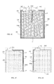
- Figs.1 to 10 which is constituted by a grid sheet, radiative grid sheet, laminate, or winding type electrode plate, wherein the single side of the electrode plate 101 is installed with one or more electric energy input/output terminals 102, and the electric energy input/output terminal 102 downward extends to one or two sides of the electrode plate 101 for installing with the insulated split-flow conductive structure 104, including extending to the imtermediate part of the side of the electrode plate 101; and/or extending to the bottom of the side of the electrode plate 101; and/or extending to the bottom of electrode plate 101 and further extending to the bottom edge of electrode plate 101.
- an electrode plate structure comprises:
Landscapes
- Chemical & Material Sciences (AREA)
- Chemical Kinetics & Catalysis (AREA)
- Electrochemistry (AREA)
- General Chemical & Material Sciences (AREA)
- Engineering & Computer Science (AREA)
- Power Engineering (AREA)
- Sustainable Energy (AREA)
- Life Sciences & Earth Sciences (AREA)
- Manufacturing & Machinery (AREA)
- Sustainable Development (AREA)
- Microelectronics & Electronic Packaging (AREA)
- Connection Of Batteries Or Terminals (AREA)
- Secondary Cells (AREA)
- Battery Electrode And Active Subsutance (AREA)
- Fuel Cell (AREA)
- Electric Double-Layer Capacitors Or The Like (AREA)
- Inert Electrodes (AREA)
- Primary Cells (AREA)
- Electron Tubes For Measurement (AREA)
- Electrostatic Separation (AREA)
Abstract
Description
- The present invention is an innovation for capacitors for electrostatic storage/discharge, or for rechargeable device with the function to transfer electric energy to chemical energy and/or transfer chemical energy to electric energy, or for electrode plate conductive structure used for fuel cell; the electrode plate of the invention is used to constitute power supply and/or rechargeable device, and the feature of the invention relates to a specifically installed insulated split-flow conductive structure with internal conductive body coated with insulator, wherein one end of the insulated split-flow conductive structure connects to the electric energy input/output terminal of the electrode plate, and another end connects to the electrode plate area where the current path more far away from the electric energy input/output terminal and/or the current passing with larger impedance, such as the surrounding part and/or the middle part and/or the bottom of the electrode plate, by way of the dedicated insulated split-flow conductive structure connecting with the electric energy input/output terminal, the electric energy, between the electrode plate area where the current path more far away from the electric energy output terminal and/or the current passing with larger impedance and the electric energy input/output terminal, specifically transmits therebetween, and the conductive body and the contacting electrochemical active substance in every area of the electrode plate can operate in more uniform current density when outputting and/or inputting electric energy.
- The conventional electrode plate is usually installed with one or more electric energy input/output terminals at single side for outputting electrical energy or charging, wherein the impedance between the electrode plate area at another side more far away from the electric energy input/output terminal and the electric energy input/output terminal, and the impedance between the electrode plate area more near the electric energy input/output terminal and the electric energy input/output terminal, the two impedances are different, thus there is a shortcoming that the current between the above both areas is uneven when outputting and/or inputting electric energy.
- The present invention relates to an equalizing electrode plate with insulated split-flow conductive structure, which is a specifically installed insulated split-flow conductive structure with internal conductive body coated with insulator, wherein one end of the insulated split-flow conductive structure connects to the electric energy input/output terminal of the electrode plate, and another end connects to the electrode plate area in the electrode plate where the current path more far away from the electric energy input/output terminal and/or the current passing with larger impedance when outputting and/or inputting electric energy, by way of the dedicated insulated split-flow conductive structure connecting with the electric energy input/output terminal, the electric energy, between the electrode plate area where the current path more far away from the electric energy output terminal and/or the electrode plate area with larger impedance and the electric energy input/output terminal, specifically transmits therebetween, and the conductive body and the contacting electrochemical active substance in every area of the electrode plate can operate in more uniform current density when outputting and/or inputting electric energy; the present invention can be applied for plate type or laminate or winding type electrode plate, or for the electrode plate constituting primary battery, rechargeable secondary battery, capacitor, or ultra-capacitor, or fuel cell for transferring chemical energy to electric energy.
-
-
Fig. 1 shows the first embodiment of the present invention; -
Fig. 2 shows the second embodiment of the present invention; -
Fig. 3 shows the third embodiment of the present invention; -
Fig. 4 shows the fourth embodiment of the present invention; -
Fig. 5 shows the fifth embodiment of the present invention; -
Fig. 6 shows the sixth embodiment of the present invention; -
Fig. 7 shows the seventh embodiment of the present invention; -
Fig. 8 shows the eighth embodiment of the present invention; -
Fig. 9 shows the ninth embodiment of the present invention; -
Fig. 10 shows the tenth embodiment of the present invention; -
Fig. 11 shows the eleventh embodiment of the present invention; -
Fig. 12 shows the 12th embodiment of the present invention; -
Fig. 13 shows the 13th embodiment of the present invention; -
Fig. 14 shows the 14th embodiment of the present invention; -
Fig. 15 shows the 15th embodiment of the present invention; -
Fig. 16 shows the 16th embodiment of the present invention; -
Fig. 17 shows the 17th embodiment ofthe present invention; -
Fig. 18 shows the 18th embodiment of the present invention; -
Fig. 19 shows the 19th embodiment of the present invention; -
Fig. 20 shows the 20th embodiment of the present invention; -
Fig. 21 shows the 21th embodiment of the present invention; -
Fig. 22 shows the 22th embodiment of the present invention; -
Fig. 23 shows the 23th embodiment of the present invention; -
Fig. 24 shows the 24th embodiment of the present invention; -
Fig. 25 shows the 25th embodiment of the present invention; -
Fig. 26 shows the second embodiment ofFig. 25 ; -
Fig. 27 shows the 27th embodiment of the present invention; -
Fig. 28 shows the 28th embodiment of the present invention; -
Fig. 29 shows the 29th embodiment of the present invention; -
Fig. 30 shows the 30th embodiment of the present invention; -
Fig. 31 shows the 31th embodiment of the present invention; -
Fig. 32 shows the 32th embodiment of the present invention; -
Fig. 33 shows the 33th embodiment of the present invention; -
Fig. 34 shows the 34th embodiment of the present invention; -
Fig. 35 shows the 35th embodiment of the present invention; -
Fig. 36 shows the 36th embodiment of the present invention; -
Fig. 37 shows the 37th embodiment of the present invention; -
Fig. 38 shows the 38th embodiment of the present invention; -
Fig. 39 shows the 39th embodiment of the present invention; -
Fig. 40 shows the 40th embodiment of the present invention; -
Fig. 41 shows the 41th embodiment of the present invention; -
Fig. 42 shows the 42th embodiment ofthe present invention; -
Fig. 43 shows the 43th embodiment of the present invention; -
Fig. 44 shows the 44th embodiment of the present invention; -
Fig. 45 shows the 45th embodiment of the present invention; -
Fig. 46 shows the 46th embodiment of the present invention; -
Fig. 47 shows the 47th embodiment of the present invention; -
Fig. 48 shows the 48th embodiment of the present invention; -
Fig. 49 shows the 49th embodiment of the present invention; -
Fig. 50 shows the 50th embodiment of the present invention; -
Fig. 51 shows the 51th embodiment of the present invention; -
Fig. 52 shows the 52th embodiment of the present invention; -
Fig. 53 shows the 53th embodiment of the present invention; -
Fig. 54 shows the 54th embodiment of the present invention; -
Fig. 55 shows the 55th embodiment of the present invention; -
Fig. 56 shows the 56th embodiment of the present invention; -
Fig. 57 shows the 57th embodiment of the present invention; -
Fig. 58 shows the 58th embodiment of the present invention; -
Fig. 59 shows the 59th embodiment of the present invention; -
Fig. 60 shows the 60th embodiment of the present invention; -
Fig. 61 shows the 61th embodiment of the present invention; -
Fig. 62 shows the 62th embodiment of the present invention; -
Fig. 63 shows the 63th embodiment of the present invention; -
Fig. 64 shows the 64th embodiment of the present invention; -
Fig. 65 shows the 65th embodiment of the present invention; -
Fig. 66 shows the 66th embodiment of the present invention; -
Fig. 67 shows the 67th embodiment of the present invention; -
Fig. 68 shows the 68th embodiment of the present invention; -
Fig. 69 shows the 69th embodiment of the present invention; -
Fig. 70 shows the 70th embodiment of the present invention; -
Fig. 71 shows the 71th embodiment of the present invention; -
Fig. 72 shows the 72th embodiment of the present invention; -
Fig. 73 shows the 73th embodiment of the present invention; -
Fig. 74 shows the 74th embodiment of the present invention; -
Fig. 75 shows the 75th embodiment of the present invention; -
Fig. 76 shows the 76th embodiment of the present invention; -
Fig. 77 shows the 77th embodiment of the present invention; -
Fig. 78 shows the 78th embodiment of the present invention; -
Fig. 79 shows the 79th embodiment of the present invention; -
Fig. 80 shows the 80th embodiment of the present invention; -
Fig. 81 shows the 81th embodiment of the present invention; -
Fig. 82 shows the 82th embodiment of the present invention; -
Fig. 83 shows the 83th embodiment of the present invention; -
Fig. 84 shows the 84th embodiment of the present invention; -
Fig. 85 shows the 85th embodiment of the present invention; -
Fig. 86 shows the 86th embodiment of the present invention; -
Fig. 87 shows the 87th embodiment of the present invention; -
Fig. 88 shows the 88th embodiment of the present invention; -
Fig. 89 shows the 89th embodiment of the present invention; -
Fig. 90 shows the 90th embodiment of the present invention; -
Fig. 91 shows the 91th embodiment of the present invention; -
Fig. 92 shows the 92th embodiment of the present invention; -
Fig. 93 shows the 93th embodiment of the present invention; -
Fig. 94 shows the 94th embodiment of the present invention; -
Fig. 95 is the A-A cross-section view of insulated split-flowconductive structure 104, according to the present invention; -
Fig. 96 is the B-B cross-section view of the conductive grid of the electrode plate, according to the present invention; -
Fig. 97 is the C-C cross-section view of the insulated split-flowconductive structure 104, according to the present invention; -
Fig. 98 is the D-D cross-section view of the insulated split-flowconductive structure 104, according to the present invention; -
Fig. 99 is the E-E cross-section view of the parallel insulated split-flowconductive structures 104, according to the present invention; -
Fig. 100 is the F-F cross-section view of two parallel insulated split-flowconductive structures conductive body 1045 of one insulated split-flowconductive structure 104 withoutinsulator 1046 installed, according to the present invention; -
Fig. 101 is the G-G cross-section view of two parallel laminated insulated split-flowconductive structures -
Fig. 102 is a cross-section view of the insulated split-flowconductive structure 1041 and/or the insulated split-flowconductive structure 1042 shown inFig. 101 , in which at least one side without insulator installed; -
Fig. 103 is the H-H cross-section view of the insulated split-flowconductive structure 104 pasted at the electrode plate at single side, according to the present invention; and -
Fig. 104 is a cross-section view of the insulated split-flowconductive structure 104 shown inFig. 103 , in which at least one side without insulator installed. -
- 101: Electrode plate
- 102: Electric energy input/output terminal
- 103: Electrochemical active substance
- 104, 1041, 1042: Insulated split-flow conductive structure
- 1023: Electric energy input/output terminal for independently inputting/outputting electric energy
- 1045: Conductive body
- 1046: Insulator
- The present invention relates to an equalizing electrode plate with insulated split-flow conductive structure, which is specifically installed insulated split-flow conductive structure with one or more internal conductive bodies coated with insulators, wherein one end of the insulated split-flow conductive structure connects to the electric energy input/output terminal of the electrode plate, and another end connects to the surrounding part and/or the middle part and/or the bottom of the electrode plate, the electrode plate area where the current path more far away from the electric energy input/output terminal and/or the current passing with larger impedance when outputting and/or inputting electric energy, by way of the dedicated insulated split-flow conductive structure connecting with the electric energy input/output terminal, the electric energy, between the electrode plate area where the current path more far away from the electric energy output terminal and/or the electrode plate area with larger impedance and the electric energy input/output terminal, specifically transmits therebetween, and the conductive body and the contacting electrochemical active substance in every area of the electrode plate can operate in more uniform current density when outputting and/or inputting electric energy.
-
Figs. 1 to 70 show the principles and foundations of the equalizing electrode plate with insulated split-flow conductive structure, according to the present invention; the following embodiments are provided to facilitate the description, and the main components include: - ---Electrode plate 101: related to positive and/or negative electrode plate constituted by grid sheet, radiative grid sheet, laminate, or winding type electrode plate, wherein the positive pole and the negative pole of the electrode plate is constituted by same or different conductive material;
- ---Electric energy input/output terminal 102: made of the electrode plate extended or being additionally installed, to connect the
electrode plate 101 at one or more sides, wherein every side is installed with one or more electric energy input/output terminals to be the interface for the electrode plate outputting and/or inputting electric energy, and the conductive material of the electric energy input/output terminal and that of the electrode plate are same or different; - ---Electrochemical active substance 103: related to electrochemical material in gaseous state, liquid state, colloidal state, or solid state; and
- ---Insulated split-flow conductive structure 104: constituted by a
conductive body 1045, whose material is same as or different from that of the electrode plate, around covered or draped with aninsulator 1046, wherein one or more insulated split-flowconductive structures 104 are installed along the side of the electrode plate and/or into the central area of the electrode plate, one end of the insulated split-flowconductive structure 104 connects in a manner of conductive features to the electric energy input/output terminal 102 of theelectrode plate 101 or the conductive body of the electrode plate, including welding, heat sealing, spot welding, mechanical riveting, locking, clamping, and blocking, and another end connects in a manner of conductive features to the electrode plate area of the electrode plate where the current path more far away from the electric energy input/output terminal 102 and/or the current passing with larger impedance when outputting and/or inputting electric energy, including welding, heat sealing, spot welding, mechanical riveting, locking, clamping and blocking, for specifically transmitting the electric energy therebetween. - For the equalizing electrode plate with insulated split-flow conductive structure, which is applied for a positive and negative electrode plate, including grid sheet, radiative grid sheet, laminate, or winding type electrode plate constituting primary battery, rechargeable secondary battery, capacitor, or ultra-capacitor, or rechargeable device or fuel cell for transferring electric energy to chemical energy or chemical energy to electric energy.
- For the equalizing electrode plate with insulated split-flow conductive structure, the
conductive body 1045 of the insulated split-flowconductive structure 104 is made of the following one or more ways, including: - (1) made of the same material as that of the electrode plate;
- (2) made of the different material, which is well conductive material with the specific resistance lower than that of the electrode plate;
- (3) made of the electrode plate material coated with the conductive body with the specific resistance lower than that of the electrode plate material; and
- (4) made of two or more different materials from that of the electrode plate, wherein the materials are ring coating with each other for two or more layers.
- The combination of the insulated split-flow
conductive structure 104 and theelectrode plate 101 is constituted by the following one or more ways, including: - (1) the insulated split-flow
conductive structure 104 and theelectrode plate 101 are integrated, wherein theconductive body 1045 of the insulated split-flowconductive structure 104 is around covered or coated with theinsulator 1046, or draped with theinsulator 1046, such as epoxy resin, insulating glue, varnish, insulating paint, or PVF, etc.; one end of the insulated split-flowconductive structure 104 and the electrode plate area set in theelectrode plate 101 for directly transmitting current to the electric energy input/output terminal 102 and/or the conductive body of theelectrode plate 101 are integrated, another end and the electric energy input/output terminal 102 or the conductive body of theelectrode plate 101 are integrated, and the current is directly transmitted in lower impedance therebetween; the insulated split-flowconductive structure 104 in flat or curved shape matches with theelectrode plate 101 to form a part of the electrode plate for being co-located in the groove structural body or case of the applying device for electrochemical action; - (2) one end of the insulated split-flow
conductive structure 104 and the electrode plate area set in theelectrode plate 101 for directly transmitting current to the electric energy input/output terminal 102 and/or the conductive body of theelectrode plate 101 are integrated, wherein theconductive body 1045 of the insulated split-flowconductive structure 104 is around covered or coated with theinsulator 1046, or draped with theinsulator 1046, such as epoxy resin, insulating glue, insulating paint, varnish, or PVF, another end is welded, riveted, clamped, or locked at the electric energy input/output terminal 102 or the conductive body of theelectrode plate 101, and the current is directly transmitted in lower impedance therebetween; the insulated split-flowconductive structure 104 in flat or curved shape matches with theelectrode plate 101 to form a part of the electrode plate for being co-located in the groove structural body or case of the applying device for electrochemical action; - (3) the insulated split-flow conductive structure 104 in the type of independent conductive line or conductive strip constitutes the conductive body 1045, the conductive body 1045 is around covered or coated with the insulator 1046, or draped with the insulator 1046, such as epoxy resin, insulating glue, insulating paint, varnish, or PVF, and the two ends of the conductive body 1045 of the insulated split-flow conductive structure 104 respectively connect in a manner of conductive features, including welding, heat sealing, spot welding, mechanical riveting, locking, clamping, and blocking, wherein one end connects to the electric energy input/output terminal 102 and/or the conductive body of the electrode plate, and another end connects to the electrode plate area set in the electrode plate 101 for directly transmitting current to the electric energy input/output terminal 102 and/or the conductive body of the electrode plate 101 and parallels the electrode plate 101; when outputting and/or inputting electric energy, the current is directly transmitted in lower impedance between the electrode plate area set in the electrode plate 101 for directly transmitting current to the electric energy input/output terminal 102 and/or the conductive body of the electrode plate 101 and the electric energy input/output terminal 102 and/or the conductive body of the electrode plate 101; and the insulated split-flow conductive structure 104 in flat or curved shape matches with the electrode plate 101 to form a part of the electrode plate for being co-located in the groove structural body or case of the applying device for electrochemical action;
- (4) the insulated split-flow conductive structure 104 in the type of independent conductive line or conductive strip constitutes the conductive body 1045, the conductive body 1045 is around covered or coated with the insulator 1046, or draped with the insulator 1046, such as epoxy resin, insulating glue, insulating paint, varnish, or PVF, and the two ends of the conductive body 1045 of the insulated split-flow conductive structure 104 respectively connect in a manner of conductive features, including welding, heat sealing, spot welding, mechanical riveting, locking, clamping, and blocking, wherein one end connects to the electric energy input/output terminal 102 and/or the conductive body of the electrode plate, and another end connects to the electrode plate area set in the electrode plate 101 for directly transmitting current to the electric energy input/output terminal 102 and/or the conductive body of the electrode plate 101; the insulated split-flow conductive structure 104 is installed and superimposed on one or two sides of the electrode plate 101; when outputting and/or inputting electric energy, the current in the current path is directly transmitted in lower impedance between the electrode plate area set in the electrode plate 101 for directly transmitting current to the electric energy input/output terminal 102 and/or the conductive body of the electrode plate 101 and the electric energy input/output terminal 102 or the conductive body of the electrode plate 101; and the insulated split-flow conductive structure 104 in flat or curved shape matches with the electrode plate 101 to form a part of the electrode plate for being co-located in the groove structural body or case of the applying device for electrochemical action; and
- (5) the independent insulated split-flow
conductive structure 104 is installed at the external part of the groove structural body or case of the electrode plate, wherein the independent insulated split-flowconductive structure 104 includes theconductive body 1045 of the insulated split-flowconductive structure 104 covered or coated with theinsulator 1046, or draped with theinsulator 1046, such as epoxy resin, insulating glue, insulating paint, varnish, or PVF, and the electrode plate area set in theelectrode plate 101 for directly transmitting current to the electric energy input/output terminal 102 and/or the conductive body of theelectrode plate 101; in the current path when outputting and/or inputting electric energy, between the electrode plate area set in theelectrode plate 101 for directly transmitting current to the electric energy input/output terminal 102 and/or the conductive body of theelectrode plate 101 and the electric energy input/output terminal 102 and/or the conductive body of theelectrode plate 101, the electric energy is directly transmitted in lower impedance therebetween, or the above both separate and respectively operate for outputting and/or inputting electric energy. - For the equalizing electrode plate with insulated split-flow conductive structure, based on the above principles, which is applied for various structural arrangements, and the following embodiments are provided only for descriptions but not limited to the applications.
- For the equalizing electrode plate with insulated split-flow conductive structure, as shown in
Figs.1 to 10 , which is constituted by a grid sheet, radiative grid sheet, laminate, or winding type electrode plate, wherein the single side of theelectrode plate 101 is installed with one or more electric energy input/output terminals 102, and the electric energy input/output terminal 102 downward extends to one or two sides of theelectrode plate 101 for installing with the insulated split-flowconductive structure 104, including extending to the imtermediate part of the side of theelectrode plate 101; and/or extending to the bottom of the side of theelectrode plate 101; and/or extending to the bottom ofelectrode plate 101 and further extending to the bottom edge ofelectrode plate 101. -
Fig. 1 shows the first embodiment of the present invention; as shown inFig. 1 , the electric energy input/output terminal 102 is installed at the left upper of theelectrode plate 101, extends along the upside of theelectrode plate 101 to the right side more far away from the electric energy input/output terminal 102, and further downward extends from the right side of theelectrode plate 101 to the bottom or near the bottom for installing with the insulated split-flowconductive structure 104, thus the input/output current is direct transmitted between the right side bottom of theelectrode plate 101 and the electric energy input/output terminal 102. -
Fig. 2 shows the second embodiment of the present invention; as shown inFig. 2 , the electric energy input/output terminal 102 is installed at the left upper of theelectrode plate 101, and extends along the left upside of theelectrode plate 101 and along the left side of theelectrode plate 101 to the bottom of theelectrode plate 101 for installing with the insulated split-flowconductive structure 104, thus the input/output current is direct transmitted between the bottom of theelectrode plate 101 and the electric energy input/output terminal 102. -
Fig. 3 shows the third embodiment of the present invention; as shown inFig. 3 , the electric energy input/output terminal 102 is installed at the upside of theelectrode plate 101, and extends along the upside of theelectrode plate 101 to the right side and the right side near the intermediate part for installing with the insulated split-flowconductive structure 104, thus the input/output current is direct transmitted between the intermediate parts of the two sides of theelectrode plate 101 and the electric energy input/output terminal 102; and the electric energy input/output terminal 102 extends along the upside of theelectrode plate 101 to the left side and the left side bottom of theelectrode plate 101 for installing with the insulated split-flowconductive structure 104, thus the input/output current is direct transmitted between the bottom of theelectrode plate 101 and the electric energy input/output terminal 102. -
Fig. 4 shows the fourth embodiment of the present invention; as shown inFig. 4 , the electric energy input/output terminal 102 is installed at the upside of theelectrode plate 101, extends along the upside of theelectrode plate 101 to the left and right sides, and further extends to the bottom for installing with the insulated split-flowconductive structure 104, thus the input/output current is direct transmitted between the bottoms of two sides of theelectrode plate 101 and the electric energy input/output terminal 102. -
Fig. 5 shows the fifth embodiment of the present invention; as shown inFig. 5 , the electric energy input/output terminal 102 is installed at the upside of theelectrode plate 101, and extends along the upside of theelectrode plate 101 to two sides for installing with the insulated split-flowconductive structure 104, in which the insulated split-flowconductive structure 104 isntalled at the left side of theelectrode plate 101 more near the electric energy input/output terminal 102 extends to the bottom near the intermediate part of theelectrode plate 101, thus the input/output current is direct transmitted between the intermediate part of the bottom of theelectrode plate 101 and the electric energy input/output terminal 102; and the insulated split-flowconductive structure 104 isntalled at the right side of theelectrode plate 101 more far away from the electric energy input/output terminal 102 extends to the intermediate part of the right side near the bottom of theelectrode plate 101, thus the input/output current is direct transmitted between the intermediate part of the right side near the bottom of theelectrode plate 101 and the electric energy input/output terminal 102. -
Fig. 6 shows the sixth embodiment of the present invention; as shown inFig. 6 , two electric energy input/output terminals 102 are installed at the upside of theelectrode plate 101, in which the electric energy input/output terminal 102 installed at the upside near the left side is more near the left side of theelectrode plate 101, the electric energy input/output terminal 102 installed at the upside near the right side is more near the right side of theelectrode plate 101, and the electric energy input/output terminal 102 installed at the upside near the right side extends along the intermediate part of the right side of theelectrode plate 101 to the position near the bottom for installing with the insulated split-flowconductive structure 104, thus the input/output current is direct transmitted between the electric energy input/output terminal 102 installed at the intermediate part of the right side near the bottom of theelectrode plate 101 and the electric energy input/output terminal 102 installed at the upside near the right side of theelectrode plate 101. -
Fig. 7 shows the seventh embodiment of the present invention; as shown inFig. 7 , two electric energy input/output terminals 102 are installed at the upside oftheelectrode plate 101, in which the electric energy input/output terminal 102 installed at the upside near the left side is more near the left side of theelectrode plate 101, the electric energy input/output terminal 102 installed at the upside near the right side is more near the right side of theelectrode plate 101, and the electric energy input/output terminal 102 installed at the upside near the right side extends along the right side of theelectrode plate 101 to the intermediate part of the bottom for installing with the insulated split-flowconductive structure 104, thus the input/output current is direct transmitted between the electric energy input/output terminal 102 installed at the intermediate part of the bottom of theelectrode plate 101 and the electric energy input/output terminal 102 installed at the upside near the right side of theelectrode plate 101. -
Fig. 8 shows the eighth embodiment of the present invention; as shown inFig. 8 , two electric energy input/output terminals 102 are installed at the upside of the electrode plate 101, in which the electric energy input/output terminal 102 installed at the upside near the left side is more near the left side of the electrode plate 101, the electric energy input/output terminal 102 installed at the upside near the right side is more near the right side of the electrode plate 101; the electric energy input/output terminal 102 installed at the upside near the left side downward extends along the left side of the electrode plate 101 to the position near the bottom for installing with the insulated split-flow conductive structure 104, thus the input/output current is direct transmitted between the electric energy input/output terminal 102 installed at the left side near the bottom of the electrode plate 101 and the electric energy input/output terminal 102 installed at the upside near the left side of the electrode plate 101; and the electric energy input/output terminal 102 installed at the upside near the right side downward extends along the right side of the electrode plate 101 to the position near the bottom for installing with the insulated split-flow conductive structure 104, thus the input/output current is direct transmitted between the electric energy input/output terminal 102 installed at the right side near the bottom of the electrode plate 101 and the electric energy input/output terminal 102 installed at the upside near the right side of the electrode plate 101. -
Fig. 9 shows the ninth embodiment of the present invention; as shown inFig. 9 , two electric energy input/output terminals 102 are installed at the upside of the electrode plate 101, in which the electric energy input/output terminal 102 installed at the upside near the left side is more near the left side of the electrode plate 101, the electric energy input/output terminal 102 installed at the upside near the right side is more near the right side of the electrode plate 101; the electric energy input/output terminal 102 installed at the upside near the left side downward extends along the left side of the electrode plate 101 to the bottom edge near the position of the intermediate part for installing with the insulated split-flow conductive structure 104, thus the input/output current is direct transmitted between the electric energy input/output terminal 102 installed at the bottom edge near the position of the intermediate part of the electrode plate 101 and the electric energy input/output terminal 102 installed at the upside near the left side of the electrode plate 101; and the electric energy input/output terminal 102 installed at the upside near the right side downward extends along the right side of the electrode plate 101 to the bottom edge near the position of the intermediate part for installing with the insulated split-flow conductive structure 104, thus the input/output current is direct transmitted between the electric energy input/output terminal 102 installed at the bottom edge near the position of the intermediate part of the electrode plate 101 and the electric energy input/output terminal 102 installed at the upside near the right side of the electrode plate 101; the bommom segment of the insulated split-flow conductive structure 104 nears or links with that of the above insulated split-flow conductive structure 104 downward extending from the left side of the electrode plate 101, and is conductive with the electrode plate 101. -
Fig. 10 shows the tenth embodiment of the present invention; as shown inFig. 10 , the electric energy input/output terminal 102 is installed at the upside of theelectrode plate 101, and downward extends along the left side and the right side of theelectrode plate 101 to the position near the bottom for installing with two insulated split-flowconductive structures 104, thus the input/output current is direct transmitted between two sides near the bottom of theelectrode plate 101 and the electric energy input/output terminal 102; and the segments of the insulated split-flowconductive structures 104 installed at two sides near the intermediate part of the bottom are respectively installed with the insulated split-flowconductive structure 104 with shunt function extending inward theelectrode plate 101, thus the input/output current is direct transmitted between the segments, near the bottom and the intermediate part of theelectrode plate 101, with shunt function extending inward theelectrode plate 101, and the electric energy input/output terminal 102.
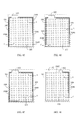
For the equalizing electrode plate with insulated split-flow conductive structure, as shown inFigs. 11 to 14 , which is constituted by a grid sheet, radiative grid sheet, laminate, or winding type electrode plate, wherein the single side of theelectrode plate 101 is installed with one or more electric energy input/output terminals 102, and the electric energy input/output terminal 102 downward extends to one or two sides of theelectrode plate 101 for installing with two or more parallel insulated split-flowconductive structures 104, each insulated split-flowconductive structure 104 downward extends to the imtermediate part of the side of theelectrode plate 101, and/or to the bottom of the side of theelectrode plate 101, and/or through the bottom of the side of theelectrode plate 101 and further to the bottom edge ofelectrode plate 101. -
Fig. 11 shows the eleventh embodiment of the present invention; as shown inFig. 11 , the electric energy input/output terminal 102 is installed at the upside near the left side of theelectrode plate 101, and extends along the upside to the right side of theelectrode plate 101 to be parallel, or as shown inFig. 99 , two insulated split-flowconductive structures conductive structure 1041 extends along the upside of theelectrode plate 101 to the right side near the intermediate part of theelectrode plate 101, thus the input/output current is direct transmitted between the intermediate part of the right side of theelectrode plate 101 and the electric energy input/output terminal 102; and the insulated split-flowconductive structure 1042 extends along the upside of theelectrode plate 101 to the right side near the bottom of theelectrode plate 101, thus the input/output current is direct transmitted between the right side bottom of theelectrode plate 101 and the electric energy input/output terminal 102. -
Fig. 12 shows the 12th embodiment of the present invention; as shown inFig. 12 , the electric energy input/output terminal 102 is installed at the upside near the left side of the electrode plate 101, and extends along the upside to the right side of the electrode plate 101 to be parallel, or as shown inFig. 99 , two insulated split-flow conductive structures 1041 and 1042 are laminated and installed, in which the insulated split-flow conductive structure 1041 extends along the upside of the electrode plate 101 to the right side near the intermediate part of the electrode plate 101, thus the input/output current is direct transmitted between the intermediate part of the right side of the electrode plate 101 and the electric energy input/output terminal 102; and the insulated split-flow conductive structure 1042 extends along the upside of the electrode plate 101 to the right side near the bottom of the electrode plate 101, thus the input/output current is direct transmitted between the right side bottom of the electrode plate 101 and the electric energy input/output terminal 102; and the electric energy input/output terminal 102 extends along the upside to the left side of the electrode plate 101, and further downward extends to the left side bottom of the electrode plate 101 for installing with the insulated split-flow conductive structure 104, thus the input/output current is direct transmitted between the left side bottom of the electrode plate 101 and the electric energy input/output terminal 102. -
Fig. 13 shows the 13th embodiment of the present invention; as shown inFig. 13 , the electric energy input/output terminal 102 is installed at the upside near the left side of theelectrode plate 101, and extends along the upside to the right side of theelectrode plate 101 to be parallel, or as shown inFig. 99 , two insulated split-flowconductive structures conductive structure 1041 extends along the upside of theelectrode plate 101 to the right side near the intermediate part of theelectrode plate 101, thus the input/output current is direct transmitted between the intermediate part of the right side of theelectrode plate 101 and the electric energy input/output terminal 102; and the insulated split-flowconductive structure 1042 extends along the upside of theelectrode plate 101 to the right side near the bottom of theelectrode plate 101, thus the input/output current is direct transmitted between the right side bottom of theelectrode plate 101 and the electric energy input/output terminal 102; and
the electric energy input/output terminal 102 extends along the upside to the left side of theelectrode plate 101 for installing with two insulated split-flowconductive structures conductive structure 1041 extends along the upside of theelectrode plate 101 to the left side near the intermediate part of theelectrode plate 101, thus the input/output current is direct transmitted between the intermediate part of the left side of theelectrode plate 101 and the electric energy input/output terminal 102; and the insulated split-flowconductive structure 1042 extends along the upside of theelectrode plate 101 to the left side near the bottom of theelectrode plate 101, thus the input/output current is direct transmitted between the left side bottom of theelectrode plate 101 and the electric energy input/output terminal 102. -
Fig. 14 shows the 14th embodiment of the present invention; as shown inFig. 14 , the electric energy input/output terminal 102 is installed at the upside near the right side of the electrode plate 101, and extends along the upside to the right side of the electrode plate 101 to be parallel, or as shown inFig. 99 , two insulated split-flow conductive structures 1041 and 1042 are laminated and installed, in which the insulated split-flow conductive structure 1041 extends along the upside of the electrode plate 101 to the region where the right side near the intermediate part and bending inwards into the electrode plate 101, thus the input/output current is direct transmitted between the electric energy input/output terminal 102 installed at the region where the intermediate part of the right side and bending inwards into the electrode plate 101 and the electric energy input/output terminal 102 installed at the upside near the right side of the electrode plate 101; and the insulated split-flow conductive structure 1042 extends along the upside of the electrode plate 101 to the right side near the bottom of the electrode plate 101, thus the input/output current is direct transmitted between the electric energy input/output terminal 102 installed at the right side bottom of the electrode plate 101 and the electric energy input/output terminal 102 installed at the upside near the right side of the electrode plate 101; and
the electric energy input/output terminal 102 extends along the upside near the left side to the left side of theelectrode plate 101 for installing with two insulated split-flowconductive structures conductive structure 1041 extends along the upside of theelectrode plate 101 to the region where the left side near the intermediate part and bending inwards into theelectrode plate 101, thus the input/output current is direct transmitted between the electric energy input/output terminal 102 installed at the region where the intermediate part of the left side and bending inwards into theelectrode plate 101 and the electric energy input/output terminal 102 installed at the upside near the left side of theelectrode plate 101; and the insulated split-flowconductive structure 1042 extends along the upside of theelectrode plate 101 to the left side near the bottom of theelectrode plate 101, thus the input/output current is direct transmitted between the left side bottom of theelectrode plate 101 and the electric energy input/output terminal 102.
For the equalizing electrode plate with insulated split-flow conductive structure, as shown inFigs. 15 to 21 , which is constituted by a grid sheet, radiative grid sheet, laminate, or winding type electrode plate, wherein one or more electric energy input/output terminals 102 are installed at each of two or more sides of theelectrode plate 101, and the electric energy input/output terminal 102 downward extends to one or two sides of theelectrode plate 101 for installing with the insulated split-flowconductive structure 104, including extending to the imtermediate part of the side of theelectrode plate 101 for installing with the insulated split-flowconductive structure 104; and/or extending to the bottom of the side of theelectrode plate 101 for installing with the insulated split-flowconductive structure 104; and/or extending to the bottom of the side of theelectrode plate 101 and further to the bottom edge ofelectrode plate 101. -
Fig. 15 shows the 15th embodiment of the present invention; as shown inFig. 15 , the electric energy input/output terminal 102 is installed at the upside of theelectrode plate 101, and downward extends along the left side of the upside to the intermediate part of the left side of theelectrode plate 101 for installing with the insulated split-flowconductive structure 104, thus the input/output current is direct transmitted between the the intermediate part of the left side of theelectrode plate 101 and the electric energy input/output terminal 102 installed at the upside of theelectrode plate 101; and the electric energy input/output terminal 102 extends along the upside of theelectrode plate 101 to the position near the right side of theelectrode plate 101 for installing with the insulated split-flowconductive structure 104, thus the input/output current is direct transmitted between the right side of theelectrode plate 101 and the electric energy input/output terminal 102 installed at the upside of theelectrode plate 101; and
the electric energy input/output terminal 102 is installed at the downside of the electrode plate 101, and upward extends from the right side of the electric energy input/output terminal 102 to the intermediate part of the right side of the electrode plate 101 for installing with the insulated split-flow conductive structure 104, thus the input/output current is direct transmitted between the the intermediate part of the right side of the electrode plate 101 and the electric energy input/output terminal 102 installed at the downside of the electrode plate 101; the electric energy input/output terminal 102 leftward extends along the downside of the electrode plate 101 to the position near the left lower of the electrode plate 101 for installing with the insulated split-flow conductive structure 104, thus the input/output current is direct transmitted between the left lower of the electrode plate 101 and the electric energy input/output terminal 102; and the electric energy input/output terminal 102 extends along the downside of the electrode plate 101 and from the downside to the intermediate part of the right side of the electrode plate 101 for installing with the insulated split-flow conductive structure 104, thus the input/output current is direct transmitted between the intermediate part of the right side of the electrode plate 101 and the electric energy input/output terminal 102 installed at the downside of the electrode plate 101. -
Fig. 16 shows the 16th embodiment of the present invention; as shown inFig. 16 , the electric energy input/output terminal 102 is installed at the left side of the upside of theelectrode plate 101, and the electric energy input/output terminal 102 is installed at the right side of the downside of the upside of theelectrode plate 101, and the insulated split-flowconductive structure 104 is installed between the left side of the electric energy input/output terminal 102 installed at the upside of theelectrode plate 101 and the segment extents along the bottom edge to the electric energy input/output terminal 102 installed at the downside of theelectrode plate 101, thus the input/output current is direct transmitted between the electric energy input/output terminal 102 installed at the upside of theelectrode plate 101 and the electric energy input/output terminal 102 installed at the upside of theelectrode plate 101. -
Fig. 17 shows the 17th embodiment of the present invention; as shown inFig. 17 , the electric energy input/output terminal 102 is installed at the left side of the upside of theelectrode plate 101, and downward extends along the right side of the upside of the electric energy input/output terminal 102 installed at the upside of theelectrode plate 101 to the position near the intermediate part of the right side of theelectrode plate 101 for installing with the insulated split-flowconductive structure 104, thus the input/output current is direct transmitted between the position near the intermediate part of the right side of theelectrode plate 101 and the electric energy input/output terminal 102 installed at the upside of theelectrode plate 101; and
the electric energy input/output terminal 102 is installed at the right side of the downside of theelectrode plate 101, and leftward and upward extends along the downside of theelectrode plate 101 to the position near the intermediate part of the left side of theelectrode plate 101 for installing with the insulated split-flowconductive structure 104, thus the input/output current is direct transmitted between the position near the intermediate part of the left side of theelectrode plate 101 and the electric energy input/output terminal 102 installed at the downside of theelectrode plate 101. -
Fig. 18 shows the 18th embodiment of the present invention; as shown inFig. 18 , the electric energy input/output terminal 102 is installed at the left side of the upside of theelectrode plate 101, and downward extends along the right side of the electric energy input/output terminal 102 installed at the upside of theelectrode plate 101 to the position near the intermediate part of the right side of theelectrode plate 101 for installing with the insulated split-flowconductive structure 104, thus the input/output current is direct transmitted between the position near the intermediate part of the right side of theelectrode plate 101 and the electric energy input/output terminal 102 installed at the upside of theelectrode plate 101; and the electric energy input/output terminal 102 installed at the upside of theelectrode plate 101 leftward and downward extends along the upside of theelectrode plate 101 to the position near the intermediate part of the left side of theelectrode plate 101 for installing with the insulated split-flowconductive structure 104, thus the input/output current is direct transmitted between the position near the intermediate part of the left side of theelectrode plate 101 and the electric energy input/output terminal 102 installed at the upside of theelectrode plate 101; and
the electric energy input/output terminal 102 is installed at the right side of the downside of theelectrode plate 101, and leftward and upward extends along the downside of theelectrode plate 101 to the position near the intermediate part of the left side of theelectrode plate 101 for installing with the insulated split-flowconductive structure 104, thus the input/output current is direct transmitted between the position near the intermediate part of the right side of theelectrode plate 101 and the electric energy input/output terminal 102 installed at the downside of theelectrode plate 101; and the electric energy input/output terminal 102 installed at the downside of theelectrode plate 101 rightward and upward extends along the downside of theelectrode plate 101 to the position near the intermediate part of the right side of theelectrode plate 101 for installing with the insulated split-flowconductive structure 104, thus the input/output current is direct transmitted between the position near the intermediate part of the right side of theelectrode plate 101 and the electric energy input/output terminal 102 installed at the downside of theelectrode plate 101. -
Fig. 19 shows the 19th embodiment of the present invention; as shown inFig. 19 , two electric energy input/output terminals 102 are installed at the upside of the electrode plate 101, in which the electric energy input/output terminal 102 installed at position near the left side of the upside is more near the left side of the upside of the electrode plate 101, and the electric energy input/output terminal 102 installed at position near the right side of the upside is more near the right side of the upside of the electrode plate 101; and two electric energy input/output terminals 102 are installed at the downside of the electrode plate 101, in which the electric energy input/output terminal 102 installed at position near the right side of the downside is more near the right side of the downside of the electrode plate 101, and the electric energy input/output terminal 102 installed at position near the left side of the downside is more near the left side of the downside of the electrode plate 101; the electric energy input/output terminal 102 installed at the position near the left side of the upside downward extends along the upside of the electrode plate 101 to the left side, and along the left side of the electrode plate 101 to the downside of the electrode plate 101, and rightward extends from the downside of the electrode plate 101 to connect the electric energy input/output terminal 102 installed at the position near the left side of the downside for installing with the insulated split-flow conductive structure 104, thus the input/output current is direct transmitted between the electric energy input/output terminal 102 installed at the position near the left side of the upside and the electric energy input/output terminal 102 installed at the position near the left side of the downside. -
Fig. 20 shows the 20th embodiment of the present invention; as shown inFig. 20 , two electric energy input/output terminals 102 are installed at the upside of the electrode plate 101, in which the electric energy input/output terminal 102 installed at position near the left side of the upside is more near the left side of the electrode plate 101, and the electric energy input/output terminal 102 installed at position near the right side of the upside is more near the right side of the electrode plate 101; and two electric energy input/output terminals 102 are installed at the downside of the electrode plate 101, in which the electric energy input/output terminal 102 installed at position near the right side of the downside is more near the right side of the electrode plate 101, and the electric energy input/output terminal 102 installed at position near the left side of the downside is more near the left side of the electrode plate 101; the electric energy input/output terminal 102 installed at the position near the left side of the upside downward extends along the neighboring left side to the electric energy input/output terminal 102 installed at the position near the left side of the downside of the left side of the neighboring bottom edge for installing with the insulated split-flow conductive structure 104, thus the input/output current is direct transmitted between the electric energy input/output terminal 102 installed at the position near the left side of the upside and the electric energy input/output terminal 102 installed at the position near the left side of the downside; and the electric energy input/output terminal 102 installed at the position near the right side of the upside downward extends along the neighboring right side to the electric energy input/output terminal 102 installed at the position near the right side of the downside of the right side of the neighboring bottom edge for installing with the insulated split-flow conductive structure 104, thus the input/output current is direct transmitted between the electric energy input/output terminal 102 installed at the position near the right side of the upside and the electric energy input/output terminal 102 installed at the position near the right side of the downside. -
Fig. 21 shows the 21th embodiment of the present invention; as shown inFig. 21 , two electric energy input/output terminals 102 are installed at the upside of the electrode plate 101, in which the electric energy input/output terminal 102 installed at position near the left side of the upside is more near the left side of the electrode plate 101, and the electric energy input/output terminal 102 installed at position near the right side of the upside is more near the right side of the electrode plate 101; the insulated split-flow conductive structure 104 is installed along the left side of the electric energy input/output terminal 102 installed at the position near the left side of the upside to the position near the intermediate part of the left side, thus the input/output current is direct transmitted between the position near the intermediate part of the left side of the electrode plate 101 and the electric energy input/output terminal 102 installed at the position near the left side of the upside; and the insulated split-flow conductive structure 104 is installed along the right side of the electric energy input/output terminal 102 installed at the position near the right side of the upside to the position near the intermediate part of the right side, thus the input/output current is direct transmitted between the position near the intermediate part of the right side of the electrode plate 101 and the electric energy input/output terminal 102 installed at the position near the right side of the upside; and
two electric energy input/output terminals 102 are installed at the downside of the electrode plate 101, in which the electric energy input/output terminal 102 installed at position near the right side of the downside is more near the right side of the downside of the electrode plate 101, and the electric energy input/output terminal 102 installed at position near the left side of the downside is more near the left side of the electrode plate 101; the insulated split-flow conductive structure 104 is installed along the left side of the electric energy input/output terminal 102 installed at the position near the left side of the downside to the position near the intermediate part of the left side of the electrode plate 101, thus the input/output current is direct transmitted between the position near the intermediate part of the left side of the electrode plate 101 and the electric energy input/output terminal 102 installed at the position near the left side of the downside; and the insulated split-flow conductive structure 104 is installed along the right side of the electric energy input/output terminal 102 installed at the position near the right side of the downside to the position near the intermediate part of the right side of the electrode plate 101, thus the input/output current is direct transmitted between the position near the intermediate part of the right side of the electrode plate 101 and the electric energy input/output terminal 102 installed at the position near the right side of the downside.
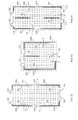
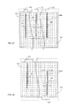
For the equalizing electrode plate with insulated split-flow conductive structure, as shown inFigs. 22 to 28 , which is constituted by a grid sheet, radiative grid sheet, laminate, or winding type electrode plate, wherein the electric energy input/output terminal 102 or the conductive body of the electrode plate 101 between two electric energy input/output terminals 102 in the non-side electrode plate region of the electrode plate 101 downward extend for installing with the insulated split-flow conductive structure 104, including extending to the intermediate region of the electrode plate, or downward extending through the intermediate region of the electrode plate 101 to the bottom edge of the electrode plate 101, or downward extending through the intermediate region of the electrode plate 101 to the bottom edge of the electrode plate 101 and further extending to the insulated split-flow conductive structure 104; and/or the electric energy input/output terminal 102 downward extends to one or two sides of the electrode plate 101 for installing with the insulated split-flow conductive structure 104, including extending to the intermediate part of the side of the electrode plate 101; and/or extending to the bottom of the side of the electrode plate 101; and/or extending to the bottom of the side of the electrode plate 101 and further extending to the bottom edge of the electrode plate 101.
As shown inFigs. 22 to 28 , the insulated split-flowconductive structure 104 is installed between the electric energy input/output terminal 102 and the intermediate part and/or the bottom of theelectrode plate 101 in the grid sheet electrode plate with the grid conductive body, according to the present invention, to make the current density when inputting/outputting current between the intermediate part or the bottom of theelectrode plate 101 and the electric energy input/output terminal 102 to be more similar with that of other regions; the related embodiments are described as following: -
Fig. 22 shows the 22th embodiment of the present invention; as shown inFig. 22 , two electric energy input/output terminals 102 are installed at the upside oftheelectrode plate 101, in which the electric energy input/output terminal 102 installed at the position near the left side of the upside is more near the left side of theelectrode plate 101, and the electric energy input/output terminal 102 installed at the position near the right side of the upside is more near the righde of theelectrode plate 101; the electric energy input/output terminal 102 installed at the position near the left side of the upside downward extends along the left side of theelectrode plate 101 to the intermediate part of the bottom edge for installing with the insulated split-flowconductive structure 104, thus the input/output current is direct transmitted between the electric energy input/output terminal 102 installed at the intermediate part of the bottom edge of the left side of theelectrode plate 101 and the electric energy input/output terminal 102 installed at the position near the left side of the upside; and
the electric energy input/output terminal 102 installed at the position near the right side of the upside downward extends along the right side of theelectrode plate 101 to the position near the bottom edge for installing with the insulated split-flowconductive structure 104, thus the input/output current is direct transmitted between the electric energy input/output terminal 102 installed at the position near the bottom edge of the right side of theelectrode plate 101 and the electric energy input/output terminal 102 installed at the position near the right side of the upside; and further
the insulated split-flowconductive structure 104 is installed at the position extended between the electric energy input/output terminal 102 installed at the position nesr the left side of the upside of theelectrode plate 101 and the electric energy input/output terminal 102 installed at position nesr the right side of the upside, to the intermediate part of theelectrode plate 101, thus the input/output current is direct transmitted between the intermediate part of theelectrode plate 101 and the position between the electric energy input/output terminal 102 installed at the position nesr the left side of the upsid and the electric energy input/output terminal 102 installed at position nesr the right side of the upside. -
Fig. 23 shows the 23th embodiment of the present invention; as shown inFig. 23 , two electric energy input/output terminals 102 are installed at the upside of theelectrode plate 101, in which the electric energy input/output terminal 102 installed at the position near the left side of the upside is more near the left side of theelectrode plate 101, and the electric energy input/output terminal 102 installed at the position near the right side of the upside is more near the right side of theelectrode plate 101; and two electric energy input/output terminals 102 are installed at the downside of theelectrode plate 101, in which the electric energy input/output terminal 102 installed at the position near the left side of the downside is more near the left side of theelectrode plate 101, and the electric energy input/output terminal 102 installed at the position near the right side of the downside is more near the right side of theelectrode plate 101; and
the electric energy input/output terminal 102 installed at the position near the left side of the upside downward extends along the left side of theelectrode plate 101 to the position near the intermediate part of the left side of theelectrode plate 101 for installing the insulated split-flowconductive structure 104, thus the input/output current is direct transmitted between the electric energy input/output terminal 102 installed at the position near the intermediate part of the left side of theelectrode plate 101 and the electric energy input/output terminal 102 installed at the position near the left side of the upside; and the electric energy input/output terminal 102 installed at the position near the right side of the upside downward extends along the right side of theelectrode plate 101 to the position near the intermediate part of the right side of theelectrode plate 101 for installing the insulated split-flowconductive structure 104, thus the input/output current is direct transmitted between the electric energy input/output terminal 102 installed at the position near the intermediate part of the right side of theelectrode plate 101 and the electric energy input/output terminal 102 installed at the position near the right side of the upside; and
the electric energy input/output terminal 102 installed at the position near the left side of the downside upward extends along the left side of theelectrode plate 101 to the position near the intermediate part of the left side of theelectrode plate 101 for installing the insulated split-flowconductive structure 104, thus the input/output current is direct transmitted between the electric energy input/output terminal 102 installed at the position near the intermediate part of the left side of theelectrode plate 101 and the electric energy input/output terminal 102 installed at the position near the left side of the downside; and the electric energy input/output terminal 102 installed at the position near the right side of the downside upward extends along the right side of theelectrode plate 101 to the position near the intermediate part of the right side of theelectrode plate 101 for installing the insulated split-flowconductive structure 104, thus the input/output current is direct transmitted between the electric energy input/output terminal 102 installed at the position near the intermediate part of the right side of theelectrode plate 101 and the electric energy input/output terminal 102 installed at the position near the right side of the downside; and
the insulated split-flowconductive structure 104 is installed at the position extended between the electric energy input/output terminal 102 installed at the position nesr the right side of the upside of theelectrode plate 101 and the electric energy input/output terminal 102 installed at position nesr the left side of the upside, to the intermediate part of theelectrode plate 101, thus the input/output current is direct transmitted between the intermediate part of theelectrode plate 101 and the position between the electric energy input/output terminal 102 installed at the position nesr the right side of the upsid and the electric energy input/output terminal 102 installed at position nesr the left side of the upside; and
the insulated split-flowconductive structure 104 is installed at the position extended between the electric energy input/output terminal 102 installed at the position nesr the right side of the downside of theelectrode plate 101 and the electric energy input/output terminal 102 installed at position nesr the left side of the downside, to the intermediate part of theelectrode plate 101, thus the input/output current is direct transmitted between the intermediate part of theelectrode plate 101 and the position between the electric energy input/output terminal 102 installed at the position nesr the right side of the downside and the electric energy input/output terminal 102 installed at position nesr the left side of the downside. -
Fig. 24 shows the 24th embodiment of the present invention; as shown inFig. 24 , two electric energy input/output terminals 102 are installed at the upside of theelectrode plate 101, in which the electric energy input/output terminal 102 installed at the position near the left side of the upside is more near the left side of theelectrode plate 101, and the electric energy input/output terminal 102 installed at the position near the right side of the upside is more near the right side of theelectrode plate 101; and
the electric energy input/output terminal 102 installed at the position near the left side of the upside downward extends along the left side of theelectrode plate 101 to the bottom edge for installing the insulated split-flowconductive structure 104, thus the input/output current is direct transmitted between the electric energy input/output terminal 102 installed at the bottom edge of the left side of theelectrode plate 101 and the electric energy input/output terminal 102 installed at the position near the left side of the upside; and the electric energy input/output terminal 102 installed at the position near the right side of the upside downward extends along the right side of theelectrode plate 101 to the bottom edge for installing the insulated split-flowconductive structure 104, thus the input/output current is direct transmitted between the electric energy input/output terminal 102 installed at the bottom edge of the right side of theelectrode plate 101 and the electric energy input/output terminal 102 installed at the position near the right side of the upside; and
the insulated split-flowconductive structure 104 is installed at the position downward extended between the electric energy input/output terminal 102 installed at the position nesr the left side of the upside of theelectrode plate 101 and the electric energy input/output terminal 102 installed at position nesr the right side of the upside, to the intermediate part of theelectrode plate 101, thus the input/output current is direct transmitted between the intermediate part of theelectrode plate 101 and the position between the electric energy input/output terminal 102 installed at the position nesr the left side of the upsid and the electric energy input/output terminal 102 installed at position nesr the right side of the upside. -
Fig. 25 shows the 25th embodiment of the present invention; as shown inFig. 25 , one or more electric energy input/output terminals 102 are installed at the upside of theelectrode plate 101, and it is characterized by the insulated split-flowconductive structure 104 installed at the position downward extended from the downside of one or more electric energy input/output terminals 102 installed at theelectrode plate 101, and through the intermediate part of theelectrode plate 101. -
Fig. 26 shows the 26th embodiment of the present invention; andFig. 26 is the second embodiment of the same structural features of the equalizing electrode plate with insulated split-flow conductive structure as shown inFig. 25 . -
Fig. 27 shows the 27th embodiment of the present invention; as shown inFig. 27 , one or more electric energy input/output terminal 102 are installed at the upside of the electrode plate 101, one or more electric energy input/output terminal 102 are installed at the downside of the electrode plate 101, and the electric energy input/output terminals 102 installed at the upside of the electrode plate 101 and the electric energy input/output terminals 102 installed at the downside of the electrode plate 101 are staggered; in which the insulated split-flow conductive structure 104 is installed at the position downward extended from the downside of the electric energy input/output terminal 102 installed at the upside of the electrode plate 101, and through the intermediate part of the electrode plate 101, thus the input/output current is direct transmitted between the electric energy input/output terminal 102 installed at the upside of the electrode plate 101 and the intermediate part of the electrode plate 101; and the insulated split-flow conductive structure 104 is installed at the position upward extended from the upside of the electric energy input/output terminal 102 installed at the downside of the electrode plate 101, and through the intermediate part of the electrode plate 101, thus the input/output current is direct transmitted between the electric energy input/output terminal 102 installed at the downside of the electrode plate 101 and the intermediate part of the electrode plate 101. -
Fig. 28 shows the 28th embodiment of the present invention; andFig. 28 is the second embodiment of the same structural features of the equalizing electrode plate with insulated split-flow conductive structure as shown inFig. 27 .
For the equalizing electrode plate with insulated split-flow conductive structure, as shown inFigs. 29 to 31 , which is constituted by a grid sheet, radiative grid sheet, laminate, or winding type electrode plate, wherein the independent insulated split-flowconductive structure 104 is additional installed at one or more sides of theelectrode plate 101, and the independent insulated split-flowconductive structure 104 includes an electric energy input/output terminal 1023 for independently inputting/outputting electric energy, which downward extends along the side of theelectrode plate 101 to the bottom of the side of theelectrode plate 101, and/or extends to the bottom of theelectrode plate 101 and further to the intermediate part of the bottom edge of theelectrode plate 101, and/or extends to the bottom of theelectrode plate 101 and further to the bottom edge of thewhole electrode plate 101. -
Fig. 29 shows the 29th embodiment of the present invention; as shown inFig. 29 , the electric energy input/output terminal 102 is installed at the upside of theelectrode plate 101, and it is characterized by the insulated split-flowconductive structure 104 independently installed from the position near the bottom edge of theelectrode plate 101, extending to the direction of the electric energy input/output terminal 102, and to the electric energy input/output terminal 1023 for independently inputting/outputting electric energy. -
Fig. 30 shows the 30th embodiment of the present invention; as shown inFig. 30 , the electric energy input/output terminal 102 is installed at the upside of theelectrode plate 101, and it is characterized by the insulated split-flowconductive structure 104 independently installed from the intermediate part of the bottom edge of theelectrode plate 101, extending to the direction of the electric energy input/output terminal 102, and to the electric energy input/output terminal 1023 for independently inputting/outputting electric energy. -
Fig. 31 shows the 31th embodiment of the present invention; as shown inFig. 31 , the electric energy input/output terminal 102 is installed at the upside of theelectrode plate 101, and it is characterized by the insulated split-flowconductive structure 104 independently installed from the bottom edge where theelectrode plate 101 and the electric energy input/output terminal 102 are diagonal, extending to the direction of the electric energy input/output terminal 102, and to the electric energy input/output terminal 1023 for independently inputting/outputting electric energy.
For the equalizing electrode plate with insulated split-flow conductive structure, as shown inFigs. 1 to 31 , wherein one or more electric energy input/output terminals 102 are installed at each of one or more sides of the electrode plate with radiative grid conductive body, and one or more insulated split-flowconductive structures 104 are installed around and/or at the intermediate part and/or at the bottom of the electric energy input/output terminal 102 and theelectrode plate 101.
As shown inFigs. 32 to 40 , which are the drawings showing the embodiments of the insulated split-flowconductive structures 104 installed between the electric energy input/output terminal 102 of the electrode plate with radiative grid conductive body and the position around the electrode plate, according to the present invention, and the descriptions are as following: -
Fig. 32 shows the 32th embodiment of the present invention; as showing inFig. 32 , the constitution is same as that of the embodiment shown inFig. 1 . -
Fig. 33 shows the 33th embodiment of the present invention; as showing inFig. 33 , the constitution of the insulated split-flowconductive structure 104 is same as that of the embodiment shown inFig. 3 . -
Fig. 34 shows the 34th embodiment of the present invention; as showing inFig. 34 , the constitution of the insulated split-flowconductive structure 104 is same as that of the embodiment shown inFig. 6 . -
Fig. 35 shows the 35th embodiment of the present invention; as showing inFig. 35 , the constitution of the insulated split-flowconductive structure 104 is same as that of the embodiment shown inFig. 8 . -
Fig. 36 shows the 36th embodiment of the present invention; as showing inFig. 36 , the constitution of the insulated split-flowconductive structure 104 is same as that of the embodiment shown inFig. 15 . -
Fig. 37 shows the 37th embodiment of the present invention; as showing inFig. 37 , the constitution of the insulated split-flowconductive structure 104 is same as that of the embodiment shown inFig. 16 . -
Fig. 38 shows the 38th embodiment of the present invention; as showing inFig. 38 , the constitution of the insulated split-flowconductive structure 104 is same as that of the embodiment shown inFig. 17 . -
Fig. 39 shows the 39th embodiment of the present invention; as shown inFig. 39 , two electric energy input/output terminals 102 are installed at the upside of theelectrode plate 101, wherein the electric energy input/output terminal 102 installed at the position near the left side of the upside is more near the left side of theelectrode plate 101, and the electric energy input/output terminal 102 installed at the position near the right side of the upside is more near the right side of theelectrode plate 101; and two electric energy input/output terminals 102 are installed at the downside of theelectrode plate 101, wherein the electric energy input/output terminal 102 installed at the position near the right side of the downside is more near the right side of theelectrode plate 101, and the electric energy input/output terminal 102 installed at the position near the left side of the downside is more near the left side of theelectrode plate 101; and
the electric energy input/output terminal 102 installed at the position near the right side of the upside downward extends along the right side to the position near the intermediate part of the right side of theelectrode plate 101 for installing with the insulated split-flowconductive structure 104, thus the input/output current is direct transmitted between the position near the intermediate part of the right side of theelectrode plate 101 and the electric energy input/output terminal 102 installed at the position near the right side of the upside; and
the electric energy input/output terminal 102 installed at the position near the ledt side of the downside upward extends along the left side to the position near the intermediate part of the left side of theelectrode plate 101 for installing with the insulated split-flowconductive structure 104, thus the input/output current is direct transmitted between the position near the intermediate part of the left side of theelectrode plate 101 1 and the electric energy input/output terminal 102 installed at the position near the left side of the downside. -
Fig. 40 shows the 40th embodiment of the present invention; as showing inFig. 40 , the constitution of the insulated split-flowconductive structure 104 is same as that of the embodiment shown inFig. 21 .
As shown inFigs. 41 to 42 , which are the drawings showing the embodiments of the insulated split-flowconductive structures 104 installed at the electric energy input/output terminal 102 and the intermediate part and/or the bottom of theelectrode plate 101 in the electrode plate with radiative grid conductive body, and the descriptions are as following: -
Fig. 41 shows the 41th embodiment of the present invention; as showing inFig. 41 , the constitution of the insulated split-flowconductive structure 104 is same as that of the embodiment shown inFig. 23 . -
Fig. 42 shows the 42th embodiment of the present invention; as showing inFig. 42 , the constitution of the insulated split-flowconductive structure 104 is same as that of the embodiment shown inFig. 24 .
For the equalizing electrode plate with insulated split-flow conductive structure, which is further constituted by the insulated split-flow conductive structure installed between the electric energy input/output terminal 102 of the laminate electrode plate and the position around and/or at the intermediate part of and/or at the bottom of thelaminate electrode plate 101.
As shown inFigs. 43 to 62 , which are the drawings showing the embodiments of the electrode plate constituted by the insulated split-flowconductive structures 104 installed between the electric energy input/output terminal 102 of the laminate electrode plate and the position around or at the bottom of theelectrode plate 101, and the descriptions are as following: -
Fig. 43 shows the 43th embodiment of the present invention; as showing inFig. 43 , the constitution of the insulated split-flowconductive structure 104 is same as that of the embodiment shown inFig. 1 . -
Fig. 44 shows the 44th embodiment of the present invention; as showing inFig. 44 , the constitution of the insulated split-flowconductive structure 104 is same as that of the embodiment shown inFig. 2 . -
Fig. 45 shows the 45th embodiment of the present invention; as showing inFig. 45 , the constitution of the insulated split-flowconductive structure 104 is same as that of the embodiment shown inFig. 3 . -
Fig. 46 shows the 46th embodiment of the present invention; as showing inFig. 46 , the constitution of the insulated split-flowconductive structure 104 is same as that of the embodiment shown inFig. 4 . -
Fig. 47 shows the 47th embodiment of the present invention; as showing inFig. 47 , the constitution of the insulated split-flowconductive structure 104 is same as that of the embodiment shown inFig. 5 . -
Fig. 48 shows the 48th embodiment of the present invention; as showing inFig. 48 , the constitution of the insulated split-flowconductive structure 104 is same as that of the embodiment shown inFig. 6 . -
Fig. 49 shows the 49th embodiment of the present invention; as showing inFig. 49 , the constitution of the insulated split-flowconductive structure 104 is same as that of the embodiment shown inFig. 7 . -
Fig. 50 shows the 50th embodiment of the present invention; as showing inFig. 50 , the constitution of the insulated split-flowconductive structure 104 is same as that of the embodiment shown inFig. 8 . -
Fig. 51 shows the 51th embodiment of the present invention; as showing inFig. 51 , the constitution of the insulated split-flowconductive structure 104 is same as that of the embodiment shown inFig. 10 . -
Fig. 52 shows the 52th embodiment of the present invention; as showing inFig. 52 , the constitution of the insulated split-flowconductive structure 104 is same as that of the embodiment shown inFig. 15 . -
Fig. 53 shows the 53th embodiment of the present invention; as showing inFig. 53 , the constitution of the insulated split-flowconductive structure 104 is same as that of the embodiment shown inFig. 11 . -
Fig. 54 shows the 54th embodiment of the present invention; as showing inFig. 54 , the constitution of the insulated split-flowconductive structure 104 is same as that of the embodiment shown inFig. 12 . -
Fig. 55 shows the 55th embodiment of the present invention; as showing inFig. 55 , the constitution of the insulated split-flowconductive structure 104 is same as that of the embodiment shown inFig. 13 . -
Fig. 56 shows the 56th embodiment of the present invention; as showing inFig. 56 , the constitution of the insulated split-flowconductive structure 104 is same as that of the embodiment shown inFig. 14 . -
Fig. 57 shows the 57th embodiment of the present invention; as showing inFig. 57 , the constitution of the insulated split-flowconductive structure 104 is same as that of the embodiment shown inFig. 16 . -
Fig. 58 shows the 58th embodiment of the present invention; as showing inFig. 58 , the constitution of the insulated split-flowconductive structure 104 is same as that of the embodiment shown inFig. 17 . -
Fig. 59 shows the 59th embodiment of the present invention; as showing inFig. 59 , the constitution of the insulated split-flowconductive structure 104 is same as that of the embodiment shown inFig. 18 . -
Fig. 60 shows the 60th embodiment of the present invention; as showing inFig. 60 , the constitution of the insulated split-flowconductive structure 104 is same as that of the embodiment shown inFig. 19 . -
Fig. 61 shows the 61th embodiment of the present invention; as showing inFig. 61 , the constitution of the insulated split-flowconductive structure 104 is same as that of the embodiment shown inFig. 20 . -
Fig. 62 shows the 62th embodiment of the present invention; as showing inFig. 62 , the constitution of the insulated split-flowconductive structure 104 is same as that of the embodiment shown inFig. 21 .
As shown inFigs. 63 to 72 , which are the drawings showing the embodiments of the insulated split-flowconductive structures 104 installed between the electric energy input/output terminal 102 of the laminate electrode plate and the intermediate part and/or the bottom of the electrode plate, according to the present invention, and the descriptions are as following: -
Fig. 63 shows the 63th embodiment of the present invention; as showing inFig. 63 , the constitution of the insulated split-flowconductive structure 104 is same as that of the embodiment shown inFig. 22 . -
Fig. 64 shows the 64th embodiment of the present invention; as showing inFig. 64 , the constitution of the insulated split-flowconductive structure 104 is same as that of the embodiment shown inFig. 23 . -
Fig. 65 shows the 65th embodiment of the present invention; as showing inFig. 65 , the constitution of the insulated split-flowconductive structure 104 is same as that of the embodiment shown inFig. 24 . -
Fig. 66 shows the 66th embodiment of the present invention; as showing inFig. 66 , the constitution of the insulated split-flowconductive structure 104 is same as that of the embodiment shown inFig. 25 . -
Fig. 67 shows the 67th embodiment of the present invention; as showing inFig. 67 , the constitution of the insulated split-flowconductive structure 104 is same as that of the embodiment shown inFig. 26 . -
Fig. 68 shows the 68th embodiment of the present invention; as showing inFig. 68 , the constitution of the insulated split-flowconductive structure 104 is same as that of the embodiment shown inFig. 27 . -
Fig. 69 shows the 69th embodiment of the present invention; as showing inFig. 69 , the constitution of the insulated split-flowconductive structure 104 is same as that of the embodiment shown inFig. 28 . -
Fig. 70 shows the 70th embodiment of the present invention; as showing inFig. 70 , the constitution of the insulated split-flowconductive structure 104 is same as that of the embodiment shown inFig. 29 . -
Fig. 71 shows the 71th embodiment of the present invention; as showing inFig. 71 , the constitution of the insulated split-flowconductive structure 104 is same as that of the embodiment shown inFig. 30 . -
Fig. 72 shows the 72th embodiment of the present invention; as showing inFig. 72 , the constitution of the insulated split-flowconductive structure 104 is same as that of the embodiment shown inFig. 31 .
For the equalizing electrode plate with insulated split-flow conductive structure, which is applied to the electrode plate constituted by the grid sheet conductive material, or radiative grid sheet, laminate, or winding type electrode plate; and there is the electric energy input/output terminal 102 with same or near width as that of the electrode plate at one or more sides of the electrode plate, in which the arrangement of the insulated split-flowconductive structure 104 is same as which, single electric energy input/output terminal installed at one or more sides of theelectrode plate 101, in the above embodiments. -
Fig. 73 shows the 73th embodiment of the present invention; as shown inFig. 73 , theelectrode plate 101 is grid sheet structure, in which the constitution of the insulated split-flowconductive structure 104 is same as that inFig. 2 , and the further feature is that there is the electric energy input/output terminal with same or near width as that of the electrode plate at one side of the electrode plate. -
Fig. 74 shows the 74th embodiment of the present invention; as shown inFig. 74 , theelectrode plate 101 is laminate structure, in which the constitution of the insulated split-flowconductive structure 104 is same as that inFig. 44 , and the further feature is that there is the electric energy input/output terminal with same or near width as that of the electrode plate at one side of the electrode plate. -
Fig. 75 shows the 75th embodiment of the present invention; as shown inFig. 75 , theelectrode plate 101 is grid sheet structure, in which the constitution of the insulated split-flowconductive structure 104 is same as that inFig. 4 , and the further feature is that there is the electric energy input/output terminal with same or near width as that of the electrode plate at one side of the electrode; plate. -
Fig. 76 shows the 76th embodiment of the present invention; as shown inFig. 76 , theelectrode plate 101 is laminate structure, in which the constitution of the insulated split-flowconductive structure 104 is same as that inFig. 46 , and the further feature is that there is the electric energy input/output terminal with same or near width as that of the electrode plate at one side of the electrode plate. -
Fig. 77 shows the 77th embodiment of the present invention; as shown inFig. 77 , theelectrode plate 101 is laminate structure, in which the electric energy input/output terminal 102 installed at the upside of theelectrode plate 101 downward extends along the left side of theelectrode plate 101 to the bottom edge near the position of the intermediate part for installing with the insulated split-flowconductive structure 104, thus the input/output current is direct transmitted between the bottom edge near the position of the intermediate part of theelectrode plate 101 and the electric energy input/output terminal 102; and the electric energy input/output terminal 102 downward extends along the right side of theelectrode plate 101 to the bottom edge near the position of the intermediate part for installing with the insulated split-flowconductive structure 104, thus the input/output current is direct transmitted between the bottom edge of the right side near the position of the intermediate part of theelectrode plate 101 and the electric energy input/output terminal 102; the bommom segment of the insulated split-flowconductive structure 104 nears or links with that of the above insulated split-flowconductive structure 104 downward extending from the left side of theelectrode plate 101, and is conductive with theelectrode plate 101. -
Fig. 78 shows the 78th embodiment of the present invention; as shown inFig. 78 , theelectrode plate 101 is laminate structure, in which the constitution of the insulated split-flowconductive structure 104 is same as that inFig. 9 . -
Fig. 79 shows the 79th embodiment of the present invention; as shown inFig. 79 , the electrode plate 101 is grid sheet structure, in which the electric energy input/output terminal 102 installed at the upside of the electrode plate 101 downward extends along the left side of the electrode plate 101 to the bottom edge near the position of the intermediate part for installing with the insulated split-flow conductive structure 104, thus the input/output current is direct transmitted between the bottom edge near the position of the intermediate part of the electrode plate 101 and the electric energy input/output terminal 102; and the electric energy input/output terminal 102 downward extends along the right side of the electrode plate 101 to the bottom edge near the position of the intermediate part for installing with the insulated split-flow conductive structure 104, thus the input/output current is direct transmitted between the bottom edge of the right side near the position of the intermediate part of the electrode plate 101 and the electric energy input/output terminal 102; the bommom segment of the insulated split-flow conductive structure 104 nears or links with that of the above insulated split-flow conductive structure 104 downward extending from the left side of the electrode plate 101, and is conductive with the electrode plate 101; and the intermediate part of the electric energy input/output terminal 102 extends to the bottom of the electrode plate 101 for installing with the insulated split-flow conductive structure 104, thus the input/output current is direct transmitted between the bottom edge of the electrode plate 101 and the intermediate part of the electric energy input/output terminal 102. -
Fig. 80 shows the 80th embodiment of the present invention; as shown inFig. 80 , theelectrode plate 101 is laminate structure, in which the constitution of the insulated split-flowconductive structure 104 is same as that inFig. 79 . -
Fig. 81 shows the 81th embodiment of the present invention; as shown inFig. 81 , theelectrode plate 101 is laminate structure, in which the electric energy input/output terminal 102 with same or near width as that of the electrode plate is installed at the upside of theelectrode plate 101; and - the intermediate part of the electric energy input/
output terminal 102 installed at the upside of theelectrode plate 101 downward extends to the position near the intermediate part region of theelectrode plate 101 for installing with the insulated split-flowconductive structure 104, thus the input/output current is direct transmitted with lower impedance between the electrode plate region set in theelectrode plate 101 1 for direct transmitting current with the electric energy input/output terminal 102, and the electric energy input/output terminal 102 linking with another side of the connecting insulated split-flowconductive structure 104. -
Fig. 82 shows the 82th embodiment of the present invention; as shown inFig. 82 , theelectrode plate 101 is laminate structure, in which the constitution of the insulated split-flowconductive structure 104 is same as that inFig. 81 . -
Fig. 83 shows the 83th embodiment of the present invention; as shown inFig. 83 , theelectrode plate 101 is grid sheet structure, in which the electric energy input/output terminal 102 with same or near width as that of the electrode plate is installed at the upside of theelectrode plate 101; and
two or more electric energy input/output terminals 102 (in the figure is represented by two) are installed at the upside of theelectrode plate 101, and the intermediate part of the electric energy input/output terminals 102 downward extend to the position near the intermediate part region of theelectrode plate 101 for installing with the insulated split-flowconductive structure 104, thus the input/output current is direct transmitted with lower impedance between the electrode plate region set in theelectrode plate 101 for direct transmitting current with the electric energy input/output terminal 102, and the electric energy input/output terminal 102 linking with another side of the connecting insulated split-flowconductive structure 104. -
Fig. 84 shows the 84th embodiment of the present invention; as shown inFig. 84 , theelectrode plate 101 is laminate structure, in which the constitution of the insulated split-flowconductive structure 104 is same as that inFig. 83 . -
Fig. 85 shows the 85th embodiment of the present invention; as shown inFig. 85 , theelectrode plate 101 is grid sheet structure, in which the electric energy input/output terminal 102 with same or near width as that of the electrode plate is installed at each of the upside and the downside of theelectrode plate 101; and
two or more intermediate part of the electric energy input/output terminals 102 (in the figure is represented by two) installed at the upside of theelectrode plate 101, and the positions near two sides of the electric energy input/output terminals 102 downward extend to the position near the intermediate part region of theelectrode plate 101 for installing with the insulated split-flowconductive structure 104, and one or more electric energy input/output terminals 102 (in the figure is represented by one) installed at intermediate part of the insulated split-flowconductive structure 104 installed at the position where the electric energy input/output terminal 102 installed at the downside of theelectrode plate 101 downward extending, upward extend to the position near the intermediate part region of theelectrode plate 101 for installing with the insulated split-flowconductive structure 104, which is the above insulated split-flowconductive structure 104 , thus the input/output current is direct transmitted with lower impedance between the electrode plate region near the intermediate part region set in theelectrode plate 101 for direct transmitting current with the electric energy input/output terminals 102 installed at the upside and the downside, and the electric energy input/output terminal 102 linking with another side of the insulated split-flowconductive structure 104 connecting with the upside and the downside. -
Fig. 86 shows the 86th embodiment of the present invention; as shown inFig. 86 , theelectrode plate 101 is laminate structure, in which the constitution of the insulated split-flowconductive structure 104 is same as that inFig. 85 .
For the equalizing electrode plate with insulated split-flow conductive structure, which is further applied to winding type electrode plate, the embodiments are as follow: -
Fig. 87 shows the 87th embodiment of the present invention; as shown inFig. 87 , the electrode plate 101 is grid sheet structure, in which at least one electric energy input/output terminal 102 is installed at the upside of the electrode plate 101, and downward extends along the left side of the electrode plate 101 to the position near the intermediate part of the bottom edge for installing with the insulated split-flow conductive structure 104, thus the input/output current is direct transmitted between the position near the intermediate part of the bottom edge of the electrode plate 101 and the electric energy input/output terminal 102; and the electric energy input/output terminal 102 installed at the most right side of the electrode plate downward extends along the right side (including the right side in the case of single electric energy input/output terminal) of the electrode plate 101 to the bottom edge for installing with the insulated split-flow conductive structure 104 along the bottom edge, thus the input/output current is direct transmitted between the bottom edge of the right side of the electrode plate 101 and the electric energy input/output terminal 102, and the bommom segment of the insulated split-flow conductive structure 104 links with that of the above insulated split-flow conductive structure 104 downward extending from the left side of the electrode plate 101, and is conductive with the electrode plate 101; if two or more electric energy input/output terminals 102 are installed, the electric energy input/output terminal 102 installed at intermediate part extends to the bottom of the electrode plate 101 for installing with the insulated split-flow conductive structure 104, thus the input/output current is direct transmitted between the bottom edge of the electrode plate 101 and the electric energy input/output terminal 102 installed at intermediate part of the electrode plate 101; and there is an isolated body installed between the electrode plate 101 and another electrode plate with different polarity for winding type structure. -
Fig. 88 shows the 88th embodiment of the present invention; as shown inFig. 88 , theelectrode plate 101 is laminate structure, in which the constitution of the insulated split-flowconductive structure 104 is same as that inFig. 87 . -
Fig. 89 shows the 89th embodiment of the present invention; as shown inFig. 89 , at least one electric energy input/output terminal 102 is installed at the upside of theelectrode plate 101, and the intermediate part of the electric energy input/output terminal 102 installed at the upside of theelectrode plate 101 downward extends to the position near the bottom edge of theelectrode plate 101 for installing with the insulated split-flowconductive structure 104, thus the input/output current is direct transmitted with lower impedance between the position near the bottom edge of theelectrode plate 101 and the electric energy input/output terminal 102 linking with another side of the connecting insulated split-flowconductive structure 104; and there is an isolated body installed between theelectrode plate 101 and another electrode plate with different polarity for winding type structure. -
Fig. 90 shows the 90th embodiment of the present invention; as shown inFig. 90 , theelectrode plate 101 is laminate structure, in which the constitution of the insulated split-flowconductive structure 104 is same as that inFig. 89 . -
Fig. 91 shows the 91th embodiment of the present invention; as shown inFig. 91 , theelectrode plate 101 is grid sheet structure, in which the electric energy input/output terminal 102 with same or near width as that of the electrode plate at the upside of the electrode plate; and
two or more electric energy input/output terminals 102 (in the figure is represented by two) are installed at the upside of the electrode plate 101, and the intermediate part of the electric energy input/output terminals 102 downward extend to the position beyond the intermediate part and near the bottom edge region of the electrode plate 101 for installing with the insulated split-flow conductive structure 104, thus the input/output current is direct transmitted with lower impedance between the electrode plate region beyond the intermediate part and near the bottom edge set in the electrode plate 101 for direct transmitting current with the electric energy input/output terminal 102, and the electric energy input/output terminal 102 linking with another side of the connecting insulated split-flow conductive structure 104; and the insulated split-flow conductive structure 104 is installed at the region where the above electric energy input/output terminals 102 downward extend to the position near the intermediate part of the electrode plate 101, thus the input/output current is direct transmitted with lower impedance between the electrode plate region beyond the intermediate part and near the intermediate edge set in the electrode plate 101 for direct transmitting current with the electric energy input/output terminal 102, and the electric energy input/output terminal 102 linking with another side of the connecting insulated split-flow conductive structure 104; and there is an isolated body installed between the electrode plate 101 and another electrode plate with different polarity for winding type structure. -
Fig. 92 shows the 92th embodiment of the present invention; as shown inFig. 92 , theelectrode plate 101 is laminate structure, in which the constitution of the insulated split-flowconductive structure 104 is same as that inFig. 91 . -
Fig. 93 shows the 94th embodiment of the present invention; as shown inFig. 93 , theelectrode plate 101 is grid sheet structure, in which the electric energy input/output terminal 102 with same or near width as that of the electrode plate is installed at each of the upside and the downside of theelectrode plate 101; and
two or more intermediate part of the electric energy input/output terminals 102 (in the figure is represented by three) installed at the upside of the electrode plate 101, and the positions near two sides of the electric energy input/output terminals 102 downward extend to the position near the intermediate part region of the electrode plate 101 for installing with the insulated split-flow conductive structure 104, and one or more electric energy input/output terminals 102 (in the figure is represented by two) installed at intermediate part of the insulated split-flow conductive structure 104 installed at the position where the electric energy input/output terminal 102 installed at the downside of the electrode plate 101 downward extending, upward extend to the position near the intermediate part region of the electrode plate 101 for installing with the insulated split-flow conductive structure 104, which is the above insulated split-flow conductive structure 104 ' thus the input/output current is direct transmitted with lower impedance between the electrode plate region near the intermediate part region set in the electrode plate 101 for direct transmitting current with the electric energy input/output terminals 102 installed at the upside and the downside, and the electric energy input/output terminal 102 linking with another side of the insulated split-flow conductive structure 104 connecting with the upside and the downside ; and there is an isolated body installed between the electrode plate 101 and another electrode plate with different polarity for winding type structure. -
Fig. 94 shows the 94th embodiment of the present invention; as shown inFig. 94 , theelectrode plate 101 is laminate structure, in which the constitution of the insulated split-flowconductive structure 104 is same as that inFig. 93 .
For the equalizing electrode plate with insulated split-flow conductive structure, the cross-section shapes of the insulated split-flowconductive structures 104 in various embodiments are as following: -
Fig. 95 is the A-A cross-section view of insulated split-flowconductive structure 104, according to the present invention; as shown inFig. 95 , the cross-section structure of the insulated split-flowconductive structure 104 is constituted by theconductive body 1045 coated with theinsulator 1046. -
Fig. 96 is the B-B cross-section view of the conductive grid of the electrode plate, according to the present invention; as shown inFig. 96 , the cross-section structure of the conductive grid electrode is constituted by the stripconductive body 1045. -
Fig. 97 is the C-C cross-section view of the insulated split-flowconductive structure 104, according to the present invention; as shown inFig. 97 , which is the cross-section structure of theconductive body 1045 of the insulated split-flowconductive structure 104, in which a side without theinsulator 1046 installed. -
Fig. 98 is the D-D cross-section view of the insulated split-flowconductive structure 104, according to the present invention; as shown inFig. 98 , which is the cross-section structure of theconductive body 1045 of the insulated split-flowconductive structure 104, in which two sides of the conductive body without theinsulator 1046 installed. -
Fig. 99 is the E-E cross-section view of the parallel insulated split-flowconductive structures 104, according to the present invention; as shown inFig. 99 , which is the cross-section structure of the two parallel insulated split-flowconductive structures 104. -
Fig. 100 is the F-F cross-section view of two parallel insulated split-flowconductive structures conductive body 1045 of one insulated split-flowconductive structure 104 without theinsulator 1046 installed, according to the present invention; as shown inFig. 100 , which is the cross-section structure of the two parallel insulated split-flowconductive structures conductive structure 104, and at least one side of theconductive body 1045 of another insulated split-flowconductive structure 104 is not installed with theinsulator 1046. -
Fig. 101 is the G-G cross-section view of two parallel laminated insulated split-flowconductive structures Fig. 101 , which is the cross-section structure of two parallel laminated insulated split-flowconductive structures 104. -
Fig. 102 is a cross-section view of the insulated split-flowconductive structure 1041 and/or the insulated split-flowconductive structure 1042 shown inFig. 101 , in which at least one side without insulator installed; as shown inFig. 102 , which is the cross-section structure of two parallel laminate insulated split-flow conductive structures, in which at least one or two sides of theconductive body 1045 without insulator installed. -
Fig. 103 is the H-H cross-section view of the insulated split-flowconductive structure 104 pasted at the electrode plate at single side, according to the present invention; as shown inFig. 103 , which is the cross-section structure of a layer of the insulated split-flowconductive structure 104 pasted at theelectrode plate 101 at single side. -
Fig. 104 is a cross-section view of the insulated split-flowconductive structure 104 shown inFig. 103 , in which at least one side without insulator installed; as shown inFig. 104 , which is the cross-section structure of a layer of the insulated split-flowconductive structure 104 pasted at theelectrode plate 101 at single side, in which at least one side of theconductive body 1045 without insulator installed. - For the above various equalizing electrode plate with insulated split-flow conductive structures, which are applied to positive and negative electrode plates constituting the electrode pair for the device with storage-discharge function, and further applied to a number of electrode pairs, which are parallel or in series, for the expansion of rated voltage and constant value current.
- According to the invention, an electrode plate structure comprises:
- an electrode plate (101);
- an electrical terminal (102) for inputting and outputting electrical energy to and from the electrode plate (101);
- an electrochemical active substance (103) provided on the electrode plate (101); and
- an insulated split-flow conductive structure (104) comprising a conductive body (1045) at least partially covered with an insulator (1046);
Claims (15)
- An equalizing electrode plate with insulated split-flow conductive structure, which is specifically installed insulated split-flow conductive structure with one or more internal conductive bodies coated with insulators, wherein one end of the insulated split-flow conductive structure connects to the electric energy input/output terminal of the electrode plate, and another end connects to the surrounding part and/or the middle part and/or the bottom of the electrode plate, the electrode plate area where the current path more far away from the electric energy input/output terminal and/or the current passing with larger impedance when outputting and/or inputting electric energy, by way of the dedicated insulated split-flow conductive structure connecting with the electric energy input/output terminal, the electric energy, between the electrode plate area where the current path more far away from the electric energy output terminal and/or the electrode plate area with larger impedance and the electric energy input/output terminal, specifically transmits therebetween, and the conductive body and the contacting electrochemical active substance in every area of the electrode plate can operate in more uniform current density when outputting and/or inputting electric energy; the main components include:---Electrode plate (101): related to positive and/or negative electrode plate constituted by grid sheet, radiative grid sheet, laminate, or winding type electrode plate, wherein the positive pole and the negative pole of the electrode plate is constituted by same or different conductive material;---Electric energy input/output terminal (102): made of the electrode plate extended or being additionally installed, to connect the electrode plate (101) at one or more sides, wherein every side is installed with one or more electric energy input/output terminals to be the interface for the electrode plate outputting and/or inputting electric energy, and the conductive material of the electric energy input/output terminal and that of the electrode plate are same or different;---Electrochemical active substance (103): related to electrochemical material in gaseous state, liquid state, colloidal state, or solid state; and---Insulated split-flow conductive structure (104): constituted by a conductive body (1045), whose material is same as or different from that of the electrode plate, around covered or draped with an insulator (1046), wherein one or more insulated split-flow conductive structures (104) are installed along the side of the electrode plate and/or into the central area of the electrode plate, one end of the insulated split-flow conductive structure (104) connects in a manner of conductive features to the electric energy input/output terminal (102) of the electrode plate (101) or the conductive body of the electrode plate, including welding, heat sealing, spot welding, mechanical riveting, locking, clamping, and blocking, and another end connects in a manner of conductive features to the electrode plate area of the electrode plate where the current path more far away from the electric energy input/output terminal (102) and/or the current passing with larger impedance when outputting and/or inputting electric energy, including welding, heat sealing, spot welding, mechanical riveting, locking, clamping and blocking, for specifically transmitting the electric energy therebetween; and in whichfor the equalizing electrode plate with insulated split-flow conductive structure, which is applied for a positive and negative electrode plate, including grid sheet, radiative grid sheet, laminate, or winding type electrode plate constituting primary battery, rechargeable secondary battery, capacitor, or ultra-capacitor, or rechargeable device or fuel cell for transferring electric energy to chemical energy or chemical energy to electric energy; and
the equalizing electrode plate with insulated split-flow conductive structure is further to use the positive and negative electrode plates constituting the electrode pair for the device with storage-discharge function, and further to use a number of electrode pairs, which are parallel or in series, for the expansion of rated voltage and constant value current. - The equalizing electrode plate with insulated split-flow conductive structure as claimed in Claim 1, wherein the conductive body (1045) of the insulated split-flow conductive structure (104) is made of the following one or more ways, including:(1) made of the same material as that of the electrode plate;(2) made of the different material, which is well conductive material with the specific resistance lower than that of the electrode plate;(3) made of the electrode plate material coated with the conductive body with the specific resistance lower than that of the electrode plate material; and(4) made of two or more different materials from that of the electrode plate, wherein the materials are ring coating with each other for two or more layers.
- The equalizing electrode plate with insulated split-flow conductive structure as claimed in Claim 1, wherein the combination of the insulated split-flow conductive structure (104) and the electrode plate (101) is constituted by the following one or more ways, including:the insulated split-flow conductive structure (104) and the electrode plate (101) are integrated, wherein the conductive body (1045) of the insulated split-flow conductive structure (104) is around covered or coated with the insulator (1046), or draped with the insulator (1046), such as epoxy resin, insulating glue, varnish, insulating paint, or PVF, etc.; one end of the insulated split-flow conductive structure (104) and the electrode plate area set in the electrode plate (101) for directly transmitting current to the electric energy input/output terminal (102) and/or the conductive body of the electrode plate (101) are integrated, another end and the electric energy input/output terminal (102) or the conductive body of the electrode plate (101) are integrated, and the current is directly transmitted in lower impedance therebetween; the insulated split-flow conductive structure (104) in flat or curved shape matches with the electrode plate (101) to form a part of the electrode plate for being co-located in the groove structural body or case of the applying device for electrochemical action.
- The equalizing electrode plate with insulated split-flow conductive structure as claimed in Claim 1, wherein the combination of the insulated split-flow conductive structure (104) and the electrode plate (101) is constituted by the following one or more ways, including:one end of the insulated split-flow conductive structure (104) and the electrode plate area set in the electrode plate (101) for directly transmitting current to the electric energy input/output terminal (102) and/or the conductive body of the electrode plate (101) are integrated, wherein the conductive body (1045) of the insulated split-flow conductive structure (104) is around covered or coated with the insulator (1046), or draped with the insulator (1046), such as epoxy resin, insulating glue, insulating paint, varnish, or PVF, another end is welded, riveted, clamped, or locked at the electric energy input/output terminal (102) or the conductive body of the electrode plate (101), and the current is directly transmitted in lower impedance therebetween; the insulated split-flow conductive structure (104) in flat or curved shape matches with the electrode plate (101) to form a part of the electrode plate for being co-located in the groove structural body or case of the applying device for electrochemical action.
- The equalizing electrode plate with insulated split-flow conductive structure as claimed in Claim 1, wherein the combination of the insulated split-flow conductive structure (104) and the electrode plate (101) is constituted by the following one or more ways, including:the insulated split-flow conductive structure (104) in the type of independent conductive line or conductive strip constitutes the conductive body (1045), the conductive body (1045) is around covered or coated with the insulator (1046), or draped with the insulator (1046), such as epoxy resin, insulating glue, insulating paint, varnish, or PVF, and the two ends of the conductive body (1045) of the insulated split-flow conductive structure (104) respectively connect in a manner of conductive features, including welding, heat sealing, spot welding, mechanical riveting, locking, clamping, and blocking, wherein one end connects to the electric energy input/output terminal (102) and/or the conductive body of the electrode plate, and another end connects to the electrode plate area set in the electrode plate (101) for directly transmitting current to the electric energy input/output terminal (102) and/or the conductive body of the electrode plate (101) and parallels the electrode plate (101); when outputting and/or inputting electric energy, the current is directly transmitted in lower impedance between the electrode plate area set in the electrode plate (101) for directly transmitting current to the electric energy input/output terminal (102) and/or the conductive body of the electrode plate (101) and the electric energy input/output terminal (102) and/or the conductive body of the electrode plate (101); and the insulated split-flow conductive structure (104) in flat or curved shape matches with the electrode plate (101) to form a part of the electrode plate for being co-located in the groove structural body or case of the applying device for electrochemical action.
- The equalizing electrode plate with insulated split-flow conductive structure as claimed in Claim 1, wherein the combination of the insulated split-flow conductive structure (104) and the electrode plate (101) is constituted by the following one or more ways, including:the insulated split-flow conductive structure (104) in the type of independent conductive line or conductive strip constitutes the conductive body (1045), the conductive body (1045) is around covered or coated with the insulator (1046), or draped with the insulator (1046), such as epoxy resin, insulating glue, insulating paint, varnish, or PVF, and the two ends of the conductive body (1045) of the insulated split-flow conductive structure (104) respectively connect in a manner of conductive features, including welding, heat sealing, spot welding, mechanical riveting, locking, clamping, and blocking, wherein one end connects to the electric energy input/output terminal (102) and/or the conductive body of the electrode plate, and another end connects to the electrode plate area set in the electrode plate (101) for directly transmitting current to the electric energy input/output terminal (102) and/or the conductive body of the electrode plate (101); the insulated split-flow conductive structure (104) is installed and superimposed on one or two sides of the electrode plate (101); when outputting and/or inputting electric energy, the current in the current path is directly transmitted in lower impedance between the electrode plate area set in the electrode plate (101) for directly transmitting current to the electric energy input/output terminal (102) and/or the conductive body of the electrode plate (101) and the electric energy input/output terminal (102) or the conductive body of the electrode plate (101); and the insulated split-flow conductive structure (104) in flat or curved shape matches with the electrode plate (101) to form a part of the electrode plate for being co-located in the groove structural body or case of the applying device for electrochemical action.
- The equalizing electrode plate with insulated split-flow conductive structure as claimed in Claim 1, wherein the combination of the insulated split-flow conductive structure (104)and the electrode plate (101) is constituted by the following one or more ways, including:the independent insulated split-flow conductive structure (104) is installed at the external part of the groove structural body or case of the electrode plate, wherein the independent insulated split-flow conductive structure (104) includes the conductive body (1045) of the insulated split-flow conductive structure (104) covered or coated with the insulator (1046), or draped with the insulator (1046), such as epoxy resin, insulating glue, insulating paint, varnish, or PVF, and the electrode plate area set in the electrode plate (101) for directly transmitting current to the electric energy input/output terminal (102) and/or the conductive body of the electrode plate (101); in the current path when outputting and/or inputting electric energy, between the electrode plate area set in the electrode plate (101) for directly transmitting current to the electric energy input/output terminal (102) and/or the conductive body of the electrode plate (101) and the electric energy input/output terminal (102) and/or the conductive body of the electrode plate (101), the electric energy is directly transmitted in lower impedance therebetween, or the above both separate and respectively operate for outputting and/or inputting electric energy.
- The equalizing electrode plate with insulated split-flow conductive structure as claimed in Claim 1, which is constituted by a grid sheet, radiative grid sheet, laminate, or winding type electrode plate, wherein the one or more than one side of the electrode plate (101) is installed one or more electric energy input/output terminals (102), and the electric energy input/output terminal (102) downward extends to one or two sides of the electrode plate (101) for installing with one or more than one parallel installed insulated split-flow conductive structure (104), including extending to the imtermediate part of the side of the electrode plate (101) to be installed with the insulated split-flow conductive structure (104); and/or extending to the bottom of the side of the electrode plate (101); and/or extending to the bottom of electrode plate (101) and further extending to the bottom edge of electrode plate (101).
- The equalizing electrode plate with insulated split-flow conductive structure as claimed in Claim 1, which is further constituted bt a grid sheet, radiative grid sheet, laminate, or winding type electrode plate, wherein the electric energy input/output terminal (102) or the conductive body of the electrode plate (101) between two electric energy input/output terminals (102) in the non-side electrode plate region of the electrode plate (101) downward extend for installing with the insulated split-flow conductive structure (104), including extending to the intermediate region of the electrode plate, or downward extending through the intermediate region of the electrode plate (101) to the bottom edge of the electrode plate (101), or downward extending through the intermediate region of the electrode plate (101) to the bottom edge of the electrode plate (101) and further extending to the insulated split-flow conductive structure (104); and/or the electric energy input/output terminal (102) downward extends to one or two sides of the electrode plate (101) for installing with the insulated split-flow conductive structure (104), including extending to the intermediate part of the side of the electrode plate (101); and/or extending to the bottom of the side of the electrode plate (101); and/or extending to the bottom of the side of the electrode plate (101) and further extending to the bottom edge of the electrode plate (101).
- The equalizing electrode plate with insulated split-flow conductive structure as claimed in Claim 1, which is constituted by a grid sheet, radiative grid sheet, laminate, or winding type electrode plate, wherein the independent insulated split-flow conductive structure (104) is additional installed at one or more sides of the electrode plate (101), and the independent insulated split-flow conductive structure (104) includes an electric energy input/output terminal (1023) for independently inputting/outputting electric energy, which downward extends along the side of the electrode plate (101) to the bottom of the side of the electrode plate (101), and/or extends to the bottom of the electrode plate (101) and further to the intermediate part of the bottom edge of the electrode plate (101), and/or extends to the bottom of the electrode plate (101) and further to the bottom edge of the whole electrode plate (101).
- The equalizing electrode plate with insulated split-flow conductive structure as claimed in Claim 1, wherein two electric energy input/output terminals (102) are installed at the upside of the electrode plate (101), the electric energy input/output terminal (102) installed at position near the left side of the upside is more near the left side of the electrode plate (101), and the electric energy input/output terminal (102) installed at position near the right side of the upside is more near the right side of the electrode plate (101); and two electric energy input/output terminals (102) are installed at the downside of the electrode plate (101), the electric energy input/output terminal (102) installed at the position near the right side of the downside is more near the right side of the electrode plate (101), and the electric energy input/output terminal (102) installed at the position near the left side of the downside is more near the left side of the electrode plate (101); and
the electric energy input/output terminal (102) installed at the position near the right side of the upside downward extends along the right side to the position near the intermediate part of the right side of the electrode plate (101) for installing with the insulated split-flow conductive structure (104), thus the input/output current is direct transmitted between the position near the intermediate part of the right side of the electrode plate (101) and the electric energy input/output terminal (102) installed at the position near the right side of the upside; and
the electric energy input/output terminal (102) installed at the position near the ledt side of the downside upward extends along the left side to the position near the intermediate part of the left side of the electrode plate (101) for installing with the insulated split-flow conductive structure (104), thus the input/output current is direct transmitted between the position near the intermediate part of the left side of the electrode plate (101) and the electric energy input/output terminal (102) installed at the position near the left side of the downside. - The equalizing electrode plate with insulated split-flow conductive structure as claimed in Claim 1, including the electrode plate constituted by the grid sheet conductive material, or radiative grid sheet, laminate, or winding type electrode plate; in which there is an electric energy input/output terminal with same or near width as that of the electrode plate at one or more sides of the electrode plate.
- The equalizing electrode plate with insulated split-flow conductive structure as claimed in Claim 1, in which at least one electric energy input/output terminal (102) is installed at the upside of the electrode plate (101), and downward extends along the left side of the electrode plate (101) to the position near the intermediate part of the bottom edge for installing with the insulated split-flow conductive structure (104), thus the input/output current is direct transmitted between the position near the intermediate part of the bottom edge of the electrode plate (101) and the electric energy input/output terminal (102); and the electric energy input/output terminal (102) installed at the most right side of the electrode plate downward extends along the right side (including the right side in the case of single electric energy input/output terminal) of the electrode plate (101) to the bottom edge for installing with the insulated split-flow conductive structure (104) along the bottom edge, thus the input/output current is direct transmitted between the bottom edge of the right side of the electrode plate (101) and the electric energy input/output terminal (102), and the bommom segment of the insulated split-flow conductive structure (104) links with that of the above insulated split-flow conductive structure (104) downward extending from the left side of the electrode plate (101), and is conductive with the electrode plate (101); if two or more electric energy input/output terminals (102) are installed, the electric energy input/output terminal (102) installed at intermediate part extends to the bottom of the electrode plate (101) for installing with the insulated split-flow conductive structure (104), thus the input/output current is direct transmitted between the bottom edge of the electrode plate (101) and the electric energy input/output terminal (102) installed at intermediate part of the electrode plate (101); and there is an isolated body installed between the electrode plate (101) and another electrode plate with different polarity for winding type structure.
- The equalizing electrode plate with insulated split-flow conductive structure as claimed in Claim 1, in which at least one electric energy input/output terminal (102) is installed at the upside of the electrode plate (101), and the intermediate part of the electric energy input/output terminal (102) installed at the upside of the electrode plate (101) downward extends to the position near the bottom edge of the electrode plate (101) for installing with the insulated split-flow conductive structure (104), thus the input/output current is direct transmitted with lower impedance between the position near the bottom edge of the electrode plate (101) and the electric energy input/output terminal (102) linking with another side of the connecting insulated split-flow conductive structure (104); and there is an isolated body installed between the electrode plate (101) and another electrode plate with different polarity for winding type structure.
- The equalizing electrode plate with insulated split-flow conductive structure as claimed in Claim 1, in which the electric energy input/output terminal (102) with same or near width as that of the electrode plate at the upside of the electrode plate; and
two or more electric energy input/output terminals (102) are installed at the upside of the electrode plate (101), and the intermediate part of the electric energy input/output terminals (102) downward extend to the position beyond the intermediate part and near the bottom edge region of the electrode plate (101) for installing with the insulated split-flow conductive structure (104), thus the input/output current is direct transmitted with lower impedance between the electrode plate region beyond the intermediate part and near the bottom edge set in the electrode plate (101) for direct transmitting current with the electric energy input/output terminal (102), and the electric energy input/output terminal (102) linking with another side of the connecting insulated split-flow conductive structure (104); and the insulated split-flow conductive structure (104) is installed at the region where the above electric energy input/output terminals (102) downward extend to the position near the intermediate part of the electrode plate (101), thus the input/output current is direct transmitted with lower impedance between the electrode plate region beyond the intermediate part and near the intermediate edge set in the electrode plate (101) for direct transmitting current with the electric energy input/output terminal (102), and the electric energy input/output terminal (102) linking with another side of the connecting insulated split-flow conductive structure (104); and there is an isolated body installed between the electrode plate (101) and another electrode plate with different polarity for winding type structure.
Applications Claiming Priority (1)
| Application Number | Priority Date | Filing Date | Title |
|---|---|---|---|
| US12/656,212 US8440355B2 (en) | 2010-01-21 | 2010-01-21 | Equalizing electrode plate with insulated split-flow conductive structure |
Publications (2)
| Publication Number | Publication Date |
|---|---|
| EP2348563A1 true EP2348563A1 (en) | 2011-07-27 |
| EP2348563B1 EP2348563B1 (en) | 2019-12-18 |
Family
ID=43989774
Family Applications (1)
| Application Number | Title | Priority Date | Filing Date |
|---|---|---|---|
| EP11151582.1A Active EP2348563B1 (en) | 2010-01-21 | 2011-01-20 | Equalizing electrode plate with insulated split-flow conductive structure |
Country Status (11)
| Country | Link |
|---|---|
| US (1) | US8440355B2 (en) |
| EP (1) | EP2348563B1 (en) |
| JP (1) | JP6085409B2 (en) |
| KR (1) | KR20120095565A (en) |
| CN (2) | CN202013916U (en) |
| AU (1) | AU2011200258B2 (en) |
| BR (1) | BRPI1105425B1 (en) |
| CA (1) | CA2728532C (en) |
| DK (1) | DK2348563T3 (en) |
| SG (1) | SG173276A1 (en) |
| TW (2) | TWI528617B (en) |
Families Citing this family (9)
| Publication number | Priority date | Publication date | Assignee | Title |
|---|---|---|---|---|
| US8551660B2 (en) * | 2009-11-30 | 2013-10-08 | Tai-Her Yang | Reserve power supply with electrode plates joined to auxiliary conductors |
| US8440355B2 (en) * | 2010-01-21 | 2013-05-14 | Tai-Her Yang | Equalizing electrode plate with insulated split-flow conductive structure |
| EP2770565A1 (en) * | 2013-02-26 | 2014-08-27 | Vito NV | Method of manufacturing gas diffusion electrodes |
| TWI655324B (en) * | 2014-02-19 | 2019-04-01 | 義大利商第諾拉工業公司 | Anode structure of electrolytic cell and metal deposition method and system in metal electrolysis field |
| KR102396108B1 (en) | 2017-06-22 | 2022-05-10 | 삼성전자주식회사 | Three-dimensional electrode structure and secondary battery including the same |
| US11404682B2 (en) * | 2017-07-05 | 2022-08-02 | Apple Inc. | Non-rectangular shaped electrodes utilizing complex shaped insulation |
| US10446823B2 (en) * | 2017-07-17 | 2019-10-15 | GM Global Technology Operations LLC | Multi-tabbed electrodes having current-optimizing electron obstacles and batteries incorporating the same |
| CN111863459B (en) * | 2020-06-28 | 2021-10-08 | 华中科技大学 | Preparation method and application of patch type micro filter capacitor |
| WO2022220526A1 (en) * | 2021-04-15 | 2022-10-20 | 주식회사 엘지에너지솔루션 | Electrode and method for manufacturing electrode |
Citations (3)
| Publication number | Priority date | Publication date | Assignee | Title |
|---|---|---|---|---|
| US3846174A (en) * | 1973-04-11 | 1974-11-05 | E Barrett | Proportioned current battery |
| US7554172B2 (en) * | 2005-04-07 | 2009-06-30 | Tai-Her Yang | Multi-directional multiplexing radius convergence electrode |
| US20090197157A1 (en) * | 2008-01-31 | 2009-08-06 | Viavattine Joseph J | Asymmetric aperture pattern in a current collector for an electrochemical cell |
Family Cites Families (10)
| Publication number | Priority date | Publication date | Assignee | Title |
|---|---|---|---|---|
| US1451058A (en) * | 1922-02-06 | 1923-04-10 | Reason P Shatzke | Grid plate for electric-current storage batteries |
| JPS4945019U (en) * | 1972-07-25 | 1974-04-20 | ||
| US3956012A (en) * | 1974-06-10 | 1976-05-11 | Scholle Corporation | Storage battery plates of plastic and lead |
| WO1983000583A1 (en) * | 1981-07-31 | 1983-02-17 | Morioka, Yuji | Lead storage battery and method of producing the same |
| JPS6223065U (en) * | 1985-07-26 | 1987-02-12 | ||
| JPH04254779A (en) * | 1991-01-30 | 1992-09-10 | Shin Kobe Electric Mach Co Ltd | Hermetically shielded type storage battery and method for testing capacity thereof |
| JP2000106167A (en) * | 1998-09-30 | 2000-04-11 | Mitsubishi Electric Corp | Battery |
| JP2005174691A (en) * | 2003-12-10 | 2005-06-30 | Nissan Motor Co Ltd | Bipolar battery |
| KR100579376B1 (en) * | 2004-10-28 | 2006-05-12 | 삼성에스디아이 주식회사 | Secondary battery |
| US8440355B2 (en) * | 2010-01-21 | 2013-05-14 | Tai-Her Yang | Equalizing electrode plate with insulated split-flow conductive structure |
-
2010
- 2010-01-21 US US12/656,212 patent/US8440355B2/en active Active
-
2011
- 2011-01-17 SG SG2011003225A patent/SG173276A1/en unknown
- 2011-01-19 JP JP2011009017A patent/JP6085409B2/en active Active
- 2011-01-20 CA CA2728532A patent/CA2728532C/en active Active
- 2011-01-20 TW TW100102090A patent/TWI528617B/en active
- 2011-01-20 EP EP11151582.1A patent/EP2348563B1/en active Active
- 2011-01-20 DK DK11151582.1T patent/DK2348563T3/en active
- 2011-01-20 TW TW100201292U patent/TWM411673U/en unknown
- 2011-01-21 CN CN2011200199869U patent/CN202013916U/en not_active Expired - Lifetime
- 2011-01-21 AU AU2011200258A patent/AU2011200258B2/en active Active
- 2011-01-21 CN CN201110023936.2A patent/CN102195047B/en active Active
- 2011-01-24 BR BRPI1105425-5A patent/BRPI1105425B1/en active IP Right Grant
- 2011-02-21 KR KR1020110014959A patent/KR20120095565A/en active Application Filing
Patent Citations (3)
| Publication number | Priority date | Publication date | Assignee | Title |
|---|---|---|---|---|
| US3846174A (en) * | 1973-04-11 | 1974-11-05 | E Barrett | Proportioned current battery |
| US7554172B2 (en) * | 2005-04-07 | 2009-06-30 | Tai-Her Yang | Multi-directional multiplexing radius convergence electrode |
| US20090197157A1 (en) * | 2008-01-31 | 2009-08-06 | Viavattine Joseph J | Asymmetric aperture pattern in a current collector for an electrochemical cell |
Also Published As
| Publication number | Publication date |
|---|---|
| JP2011151024A (en) | 2011-08-04 |
| CA2728532A1 (en) | 2011-07-21 |
| KR20120095565A (en) | 2012-08-29 |
| AU2011200258B2 (en) | 2016-01-28 |
| CN102195047B (en) | 2015-11-25 |
| AU2011200258A1 (en) | 2011-08-04 |
| US8440355B2 (en) | 2013-05-14 |
| CN202013916U (en) | 2011-10-19 |
| SG173276A1 (en) | 2011-08-29 |
| US20110177394A1 (en) | 2011-07-21 |
| TWM411673U (en) | 2011-09-11 |
| CA2728532C (en) | 2018-05-22 |
| DK2348563T3 (en) | 2020-03-16 |
| BRPI1105425A2 (en) | 2013-07-16 |
| EP2348563B1 (en) | 2019-12-18 |
| TW201140912A (en) | 2011-11-16 |
| TWI528617B (en) | 2016-04-01 |
| BRPI1105425B1 (en) | 2020-08-25 |
| CN102195047A (en) | 2011-09-21 |
| JP6085409B2 (en) | 2017-02-22 |
Similar Documents
| Publication | Publication Date | Title |
|---|---|---|
| CA2728532C (en) | Equalizing electrode plate with insulated split-flow conductive structure | |
| US9806321B2 (en) | Electrode assembly having compact electrode tabs and secondary battery using the same | |
| US8098483B2 (en) | Multi electrode series connected arrangement supercapacitor | |
| KR102032773B1 (en) | Battery Cell Having Double Welding Structure | |
| JP4864427B2 (en) | Manufacturing method of electric double layer capacitor | |
| KR100858790B1 (en) | Secondary Battery of High Capacity and Excellent Stability | |
| KR102119535B1 (en) | Battery Cell Comprising Electrode Lead Facing Outer Surface of Electrode Assembly | |
| JP2012516009A (en) | Electrochemical energy storage cell | |
| KR20100062911A (en) | Electrode plate multi-end sides to single end side current collector of an electricity storage/discharge device | |
| KR20130063890A (en) | Electrode assembly and secondary battery having the same | |
| WO2012043737A1 (en) | Electricity storage package structure, electrochemical device, and electrochemical module | |
| KR102614018B1 (en) | Rechargeable battery, bipolar electrode and bipolar electrode manufacturing method | |
| JP2013021326A (en) | Super capacitor cell and super capacitor module including multiple cells | |
| JP5925142B2 (en) | Secondary battery | |
| JP6314658B2 (en) | Power storage device | |
| KR102122684B1 (en) | Equalizing electrode plate with insulated split-flow conductive structure | |
| US20210296630A1 (en) | Secondary battery using bipolar electrode | |
| JP3168167U (en) | Electrode plate | |
| JP3246636U (en) | Soft-pack battery module and its power supply | |
| EP4376207A1 (en) | Secondary battery having improved terminal structure | |
| CN115117522B (en) | Soft package type battery module and electric energy supply device thereof | |
| KR20220002301U (en) | Parallel battery cell with heat dissipating leads | |
| JP2012221688A (en) | Stacked battery |
Legal Events
| Date | Code | Title | Description |
|---|---|---|---|
| PUAI | Public reference made under article 153(3) epc to a published international application that has entered the european phase |
Free format text: ORIGINAL CODE: 0009012 |
|
| AK | Designated contracting states |
Kind code of ref document: A1 Designated state(s): AL AT BE BG CH CY CZ DE DK EE ES FI FR GB GR HR HU IE IS IT LI LT LU LV MC MK MT NL NO PL PT RO RS SE SI SK SM TR |
|
| AX | Request for extension of the european patent |
Extension state: BA ME |
|
| 17P | Request for examination filed |
Effective date: 20120120 |
|
| 17Q | First examination report despatched |
Effective date: 20160419 |
|
| STAA | Information on the status of an ep patent application or granted ep patent |
Free format text: STATUS: EXAMINATION IS IN PROGRESS |
|
| GRAP | Despatch of communication of intention to grant a patent |
Free format text: ORIGINAL CODE: EPIDOSNIGR1 |
|
| RIC1 | Information provided on ipc code assigned before grant |
Ipc: H01M 4/72 20060101ALI20181204BHEP Ipc: H01M 2/26 20060101ALI20181204BHEP Ipc: H01M 4/70 20060101AFI20181204BHEP Ipc: H01M 8/0247 20160101ALI20181204BHEP Ipc: H01G 11/26 20130101ALI20181204BHEP |
|
| STAA | Information on the status of an ep patent application or granted ep patent |
Free format text: STATUS: GRANT OF PATENT IS INTENDED |
|
| INTG | Intention to grant announced |
Effective date: 20190110 |
|
| RIC1 | Information provided on ipc code assigned before grant |
Ipc: H01G 11/26 20130101ALI20181204BHEP Ipc: H01M 4/70 20060101AFI20181204BHEP Ipc: H01M 2/26 20060101ALI20181204BHEP Ipc: H01M 4/72 20060101ALI20181204BHEP Ipc: H01M 8/0247 20160101ALI20181204BHEP |
|
| GRAS | Grant fee paid |
Free format text: ORIGINAL CODE: EPIDOSNIGR3 |
|
| GRAA | (expected) grant |
Free format text: ORIGINAL CODE: 0009210 |
|
| STAA | Information on the status of an ep patent application or granted ep patent |
Free format text: STATUS: THE PATENT HAS BEEN GRANTED |
|
| AK | Designated contracting states |
Kind code of ref document: B1 Designated state(s): AL AT BE BG CH CY CZ DE DK EE ES FI FR GB GR HR HU IE IS IT LI LT LU LV MC MK MT NL NO PL PT RO RS SE SI SK SM TR |
|
| REG | Reference to a national code |
Ref country code: GB Ref legal event code: FG4D |
|
| REG | Reference to a national code |
Ref country code: CH Ref legal event code: EP |
|
| REG | Reference to a national code |
Ref country code: DE Ref legal event code: R096 Ref document number: 602011064051 Country of ref document: DE |
|
| REG | Reference to a national code |
Ref country code: IE Ref legal event code: FG4D |
|
| REG | Reference to a national code |
Ref country code: AT Ref legal event code: REF Ref document number: 1215581 Country of ref document: AT Kind code of ref document: T Effective date: 20200115 |
|
| REG | Reference to a national code |
Ref country code: CH Ref legal event code: NV Representative=s name: VALIPAT S.A. C/O BOVARD SA NEUCHATEL, CH |
|
| REG | Reference to a national code |
Ref country code: DK Ref legal event code: T3 Effective date: 20200309 |
|
| REG | Reference to a national code |
Ref country code: NL Ref legal event code: FP |
|
| REG | Reference to a national code |
Ref country code: SE Ref legal event code: TRGR |
|
| PG25 | Lapsed in a contracting state [announced via postgrant information from national office to epo] |
Ref country code: NO Free format text: LAPSE BECAUSE OF FAILURE TO SUBMIT A TRANSLATION OF THE DESCRIPTION OR TO PAY THE FEE WITHIN THE PRESCRIBED TIME-LIMIT Effective date: 20200318 Ref country code: GR Free format text: LAPSE BECAUSE OF FAILURE TO SUBMIT A TRANSLATION OF THE DESCRIPTION OR TO PAY THE FEE WITHIN THE PRESCRIBED TIME-LIMIT Effective date: 20200319 Ref country code: LV Free format text: LAPSE BECAUSE OF FAILURE TO SUBMIT A TRANSLATION OF THE DESCRIPTION OR TO PAY THE FEE WITHIN THE PRESCRIBED TIME-LIMIT Effective date: 20191218 Ref country code: BG Free format text: LAPSE BECAUSE OF FAILURE TO SUBMIT A TRANSLATION OF THE DESCRIPTION OR TO PAY THE FEE WITHIN THE PRESCRIBED TIME-LIMIT Effective date: 20200318 Ref country code: FI Free format text: LAPSE BECAUSE OF FAILURE TO SUBMIT A TRANSLATION OF THE DESCRIPTION OR TO PAY THE FEE WITHIN THE PRESCRIBED TIME-LIMIT Effective date: 20191218 Ref country code: LT Free format text: LAPSE BECAUSE OF FAILURE TO SUBMIT A TRANSLATION OF THE DESCRIPTION OR TO PAY THE FEE WITHIN THE PRESCRIBED TIME-LIMIT Effective date: 20191218 |
|
| REG | Reference to a national code |
Ref country code: LT Ref legal event code: MG4D |
|
| PG25 | Lapsed in a contracting state [announced via postgrant information from national office to epo] |
Ref country code: HR Free format text: LAPSE BECAUSE OF FAILURE TO SUBMIT A TRANSLATION OF THE DESCRIPTION OR TO PAY THE FEE WITHIN THE PRESCRIBED TIME-LIMIT Effective date: 20191218 Ref country code: RS Free format text: LAPSE BECAUSE OF FAILURE TO SUBMIT A TRANSLATION OF THE DESCRIPTION OR TO PAY THE FEE WITHIN THE PRESCRIBED TIME-LIMIT Effective date: 20191218 |
|
| PG25 | Lapsed in a contracting state [announced via postgrant information from national office to epo] |
Ref country code: AL Free format text: LAPSE BECAUSE OF FAILURE TO SUBMIT A TRANSLATION OF THE DESCRIPTION OR TO PAY THE FEE WITHIN THE PRESCRIBED TIME-LIMIT Effective date: 20191218 |
|
| PG25 | Lapsed in a contracting state [announced via postgrant information from national office to epo] |
Ref country code: CZ Free format text: LAPSE BECAUSE OF FAILURE TO SUBMIT A TRANSLATION OF THE DESCRIPTION OR TO PAY THE FEE WITHIN THE PRESCRIBED TIME-LIMIT Effective date: 20191218 Ref country code: PT Free format text: LAPSE BECAUSE OF FAILURE TO SUBMIT A TRANSLATION OF THE DESCRIPTION OR TO PAY THE FEE WITHIN THE PRESCRIBED TIME-LIMIT Effective date: 20200513 Ref country code: RO Free format text: LAPSE BECAUSE OF FAILURE TO SUBMIT A TRANSLATION OF THE DESCRIPTION OR TO PAY THE FEE WITHIN THE PRESCRIBED TIME-LIMIT Effective date: 20191218 Ref country code: EE Free format text: LAPSE BECAUSE OF FAILURE TO SUBMIT A TRANSLATION OF THE DESCRIPTION OR TO PAY THE FEE WITHIN THE PRESCRIBED TIME-LIMIT Effective date: 20191218 |
|
| PG25 | Lapsed in a contracting state [announced via postgrant information from national office to epo] |
Ref country code: SM Free format text: LAPSE BECAUSE OF FAILURE TO SUBMIT A TRANSLATION OF THE DESCRIPTION OR TO PAY THE FEE WITHIN THE PRESCRIBED TIME-LIMIT Effective date: 20191218 Ref country code: IS Free format text: LAPSE BECAUSE OF FAILURE TO SUBMIT A TRANSLATION OF THE DESCRIPTION OR TO PAY THE FEE WITHIN THE PRESCRIBED TIME-LIMIT Effective date: 20200418 Ref country code: SK Free format text: LAPSE BECAUSE OF FAILURE TO SUBMIT A TRANSLATION OF THE DESCRIPTION OR TO PAY THE FEE WITHIN THE PRESCRIBED TIME-LIMIT Effective date: 20191218 |
|
| REG | Reference to a national code |
Ref country code: DE Ref legal event code: R097 Ref document number: 602011064051 Country of ref document: DE |
|
| PG25 | Lapsed in a contracting state [announced via postgrant information from national office to epo] |
Ref country code: MC Free format text: LAPSE BECAUSE OF FAILURE TO SUBMIT A TRANSLATION OF THE DESCRIPTION OR TO PAY THE FEE WITHIN THE PRESCRIBED TIME-LIMIT Effective date: 20191218 |
|
| REG | Reference to a national code |
Ref country code: AT Ref legal event code: MK05 Ref document number: 1215581 Country of ref document: AT Kind code of ref document: T Effective date: 20191218 Ref country code: BE Ref legal event code: MM Effective date: 20200131 |
|
| PLBE | No opposition filed within time limit |
Free format text: ORIGINAL CODE: 0009261 |
|
| STAA | Information on the status of an ep patent application or granted ep patent |
Free format text: STATUS: NO OPPOSITION FILED WITHIN TIME LIMIT |
|
| PG25 | Lapsed in a contracting state [announced via postgrant information from national office to epo] |
Ref country code: LU Free format text: LAPSE BECAUSE OF NON-PAYMENT OF DUE FEES Effective date: 20200120 Ref country code: ES Free format text: LAPSE BECAUSE OF FAILURE TO SUBMIT A TRANSLATION OF THE DESCRIPTION OR TO PAY THE FEE WITHIN THE PRESCRIBED TIME-LIMIT Effective date: 20191218 |
|
| 26N | No opposition filed |
Effective date: 20200921 |
|
| PG25 | Lapsed in a contracting state [announced via postgrant information from national office to epo] |
Ref country code: AT Free format text: LAPSE BECAUSE OF FAILURE TO SUBMIT A TRANSLATION OF THE DESCRIPTION OR TO PAY THE FEE WITHIN THE PRESCRIBED TIME-LIMIT Effective date: 20191218 Ref country code: BE Free format text: LAPSE BECAUSE OF NON-PAYMENT OF DUE FEES Effective date: 20200131 Ref country code: SI Free format text: LAPSE BECAUSE OF FAILURE TO SUBMIT A TRANSLATION OF THE DESCRIPTION OR TO PAY THE FEE WITHIN THE PRESCRIBED TIME-LIMIT Effective date: 20191218 |
|
| PG25 | Lapsed in a contracting state [announced via postgrant information from national office to epo] |
Ref country code: IE Free format text: LAPSE BECAUSE OF NON-PAYMENT OF DUE FEES Effective date: 20200120 |
|
| PG25 | Lapsed in a contracting state [announced via postgrant information from national office to epo] |
Ref country code: PL Free format text: LAPSE BECAUSE OF FAILURE TO SUBMIT A TRANSLATION OF THE DESCRIPTION OR TO PAY THE FEE WITHIN THE PRESCRIBED TIME-LIMIT Effective date: 20191218 |
|
| PG25 | Lapsed in a contracting state [announced via postgrant information from national office to epo] |
Ref country code: TR Free format text: LAPSE BECAUSE OF FAILURE TO SUBMIT A TRANSLATION OF THE DESCRIPTION OR TO PAY THE FEE WITHIN THE PRESCRIBED TIME-LIMIT Effective date: 20191218 Ref country code: MT Free format text: LAPSE BECAUSE OF FAILURE TO SUBMIT A TRANSLATION OF THE DESCRIPTION OR TO PAY THE FEE WITHIN THE PRESCRIBED TIME-LIMIT Effective date: 20191218 Ref country code: CY Free format text: LAPSE BECAUSE OF FAILURE TO SUBMIT A TRANSLATION OF THE DESCRIPTION OR TO PAY THE FEE WITHIN THE PRESCRIBED TIME-LIMIT Effective date: 20191218 |
|
| PG25 | Lapsed in a contracting state [announced via postgrant information from national office to epo] |
Ref country code: MK Free format text: LAPSE BECAUSE OF FAILURE TO SUBMIT A TRANSLATION OF THE DESCRIPTION OR TO PAY THE FEE WITHIN THE PRESCRIBED TIME-LIMIT Effective date: 20191218 |
|
| PGFP | Annual fee paid to national office [announced via postgrant information from national office to epo] |
Ref country code: DK Payment date: 20230130 Year of fee payment: 13 |
|
| PGFP | Annual fee paid to national office [announced via postgrant information from national office to epo] |
Ref country code: NL Payment date: 20240131 Year of fee payment: 14 |
|
| PGFP | Annual fee paid to national office [announced via postgrant information from national office to epo] |
Ref country code: DE Payment date: 20240219 Year of fee payment: 14 Ref country code: GB Payment date: 20240131 Year of fee payment: 14 Ref country code: CH Payment date: 20240212 Year of fee payment: 14 |
|
| PGFP | Annual fee paid to national office [announced via postgrant information from national office to epo] |
Ref country code: SE Payment date: 20240131 Year of fee payment: 14 Ref country code: IT Payment date: 20240131 Year of fee payment: 14 Ref country code: FR Payment date: 20240131 Year of fee payment: 14 |